EP3553866A1 - Katalysatormaterial für eine brennstoffzelle, sowie herstellungsverfahren - Google Patents
Katalysatormaterial für eine brennstoffzelle, sowie herstellungsverfahren Download PDFInfo
- Publication number
- EP3553866A1 EP3553866A1 EP18167304.7A EP18167304A EP3553866A1 EP 3553866 A1 EP3553866 A1 EP 3553866A1 EP 18167304 A EP18167304 A EP 18167304A EP 3553866 A1 EP3553866 A1 EP 3553866A1
- Authority
- EP
- European Patent Office
- Prior art keywords
- catalyst material
- catalyst
- fuel cell
- nife
- material according
- Prior art date
- Legal status (The legal status is an assumption and is not a legal conclusion. Google has not performed a legal analysis and makes no representation as to the accuracy of the status listed.)
- Withdrawn
Links
- 239000003054 catalyst Substances 0.000 title claims abstract description 91
- 239000000463 material Substances 0.000 title claims abstract description 71
- 239000000446 fuel Substances 0.000 title claims abstract description 41
- 238000000034 method Methods 0.000 title claims description 17
- 229910000314 transition metal oxide Inorganic materials 0.000 claims abstract description 17
- 150000001875 compounds Chemical class 0.000 claims abstract description 16
- 238000009830 intercalation Methods 0.000 claims abstract description 15
- 230000002687 intercalation Effects 0.000 claims abstract description 15
- 230000001172 regenerating effect Effects 0.000 claims abstract description 13
- 229910001030 Iron–nickel alloy Inorganic materials 0.000 claims abstract description 11
- 230000002441 reversible effect Effects 0.000 claims abstract description 11
- 229910052760 oxygen Inorganic materials 0.000 claims description 36
- 239000001301 oxygen Substances 0.000 claims description 35
- QVGXLLKOCUKJST-UHFFFAOYSA-N atomic oxygen Chemical compound [O] QVGXLLKOCUKJST-UHFFFAOYSA-N 0.000 claims description 34
- PXHVJJICTQNCMI-UHFFFAOYSA-N Nickel Chemical compound [Ni] PXHVJJICTQNCMI-UHFFFAOYSA-N 0.000 claims description 30
- OKTJSMMVPCPJKN-UHFFFAOYSA-N Carbon Chemical compound [C] OKTJSMMVPCPJKN-UHFFFAOYSA-N 0.000 claims description 29
- KFZMGEQAYNKOFK-UHFFFAOYSA-N Isopropanol Chemical compound CC(C)O KFZMGEQAYNKOFK-UHFFFAOYSA-N 0.000 claims description 28
- AMWRITDGCCNYAT-UHFFFAOYSA-L hydroxy(oxo)manganese;manganese Chemical compound [Mn].O[Mn]=O.O[Mn]=O AMWRITDGCCNYAT-UHFFFAOYSA-L 0.000 claims description 24
- 229910052799 carbon Inorganic materials 0.000 claims description 23
- XLYOFNOQVPJJNP-UHFFFAOYSA-N water Substances O XLYOFNOQVPJJNP-UHFFFAOYSA-N 0.000 claims description 20
- 239000011230 binding agent Substances 0.000 claims description 17
- 239000002019 doping agent Substances 0.000 claims description 16
- 229910052759 nickel Inorganic materials 0.000 claims description 16
- 229960004592 isopropanol Drugs 0.000 claims description 14
- 239000012528 membrane Substances 0.000 claims description 14
- 239000012876 carrier material Substances 0.000 claims description 13
- RYGMFSIKBFXOCR-UHFFFAOYSA-N Copper Chemical compound [Cu] RYGMFSIKBFXOCR-UHFFFAOYSA-N 0.000 claims description 12
- XEEYBQQBJWHFJM-UHFFFAOYSA-N Iron Chemical compound [Fe] XEEYBQQBJWHFJM-UHFFFAOYSA-N 0.000 claims description 12
- 229910052802 copper Inorganic materials 0.000 claims description 12
- 239000010949 copper Substances 0.000 claims description 12
- 239000000758 substrate Substances 0.000 claims description 12
- GUTLYIVDDKVIGB-UHFFFAOYSA-N cobalt atom Chemical compound [Co] GUTLYIVDDKVIGB-UHFFFAOYSA-N 0.000 claims description 11
- 229910052709 silver Inorganic materials 0.000 claims description 11
- 230000008569 process Effects 0.000 claims description 10
- BQCADISMDOOEFD-UHFFFAOYSA-N Silver Chemical compound [Ag] BQCADISMDOOEFD-UHFFFAOYSA-N 0.000 claims description 9
- 229910017052 cobalt Inorganic materials 0.000 claims description 9
- 239000010941 cobalt Substances 0.000 claims description 9
- 239000000203 mixture Substances 0.000 claims description 9
- 239000002245 particle Substances 0.000 claims description 9
- NUJOXMJBOLGQSY-UHFFFAOYSA-N manganese dioxide Chemical compound O=[Mn]=O NUJOXMJBOLGQSY-UHFFFAOYSA-N 0.000 claims description 8
- 239000006229 carbon black Substances 0.000 claims description 7
- 238000009792 diffusion process Methods 0.000 claims description 7
- 239000007789 gas Substances 0.000 claims description 7
- 239000004332 silver Substances 0.000 claims description 7
- 239000003014 ion exchange membrane Substances 0.000 claims description 6
- 229910052742 iron Inorganic materials 0.000 claims description 5
- 229920000642 polymer Polymers 0.000 claims description 5
- 239000007787 solid Substances 0.000 claims description 5
- 229910021393 carbon nanotube Inorganic materials 0.000 claims description 4
- 239000002041 carbon nanotube Substances 0.000 claims description 4
- 239000012498 ultrapure water Substances 0.000 claims description 4
- 239000006185 dispersion Substances 0.000 claims description 3
- 229910021389 graphene Inorganic materials 0.000 claims description 3
- 229920002492 poly(sulfone) Polymers 0.000 claims description 3
- 238000002156 mixing Methods 0.000 claims description 2
- 150000003856 quaternary ammonium compounds Chemical class 0.000 claims 1
- 125000000542 sulfonic acid group Chemical group 0.000 claims 1
- 238000005868 electrolysis reaction Methods 0.000 abstract description 4
- 238000004519 manufacturing process Methods 0.000 abstract description 4
- 230000000694 effects Effects 0.000 description 30
- 239000000306 component Substances 0.000 description 27
- 238000006243 chemical reaction Methods 0.000 description 22
- 239000001257 hydrogen Substances 0.000 description 17
- 229910052739 hydrogen Inorganic materials 0.000 description 17
- UFHFLCQGNIYNRP-UHFFFAOYSA-N Hydrogen Chemical compound [H][H] UFHFLCQGNIYNRP-UHFFFAOYSA-N 0.000 description 13
- 238000006722 reduction reaction Methods 0.000 description 9
- 230000008901 benefit Effects 0.000 description 8
- 239000010411 electrocatalyst Substances 0.000 description 8
- 230000001588 bifunctional effect Effects 0.000 description 7
- BASFCYQUMIYNBI-UHFFFAOYSA-N platinum Substances [Pt] BASFCYQUMIYNBI-UHFFFAOYSA-N 0.000 description 7
- 235000019241 carbon black Nutrition 0.000 description 6
- 238000005259 measurement Methods 0.000 description 6
- 229910000510 noble metal Inorganic materials 0.000 description 6
- 229910052723 transition metal Inorganic materials 0.000 description 6
- 150000003624 transition metals Chemical class 0.000 description 6
- 150000002431 hydrogen Chemical class 0.000 description 5
- 230000007774 longterm Effects 0.000 description 5
- 238000007254 oxidation reaction Methods 0.000 description 5
- 238000006555 catalytic reaction Methods 0.000 description 4
- 239000004020 conductor Substances 0.000 description 4
- 230000007797 corrosion Effects 0.000 description 4
- 238000005260 corrosion Methods 0.000 description 4
- -1 however Substances 0.000 description 4
- XLYOFNOQVPJJNP-UHFFFAOYSA-M hydroxide Chemical compound [OH-] XLYOFNOQVPJJNP-UHFFFAOYSA-M 0.000 description 4
- 239000000976 ink Substances 0.000 description 4
- 229910052751 metal Inorganic materials 0.000 description 4
- 239000002184 metal Substances 0.000 description 4
- 230000009467 reduction Effects 0.000 description 4
- 239000002904 solvent Substances 0.000 description 4
- 239000000725 suspension Substances 0.000 description 4
- PWHULOQIROXLJO-UHFFFAOYSA-N Manganese Chemical compound [Mn] PWHULOQIROXLJO-UHFFFAOYSA-N 0.000 description 3
- 229920000557 Nafion® Polymers 0.000 description 3
- 238000002441 X-ray diffraction Methods 0.000 description 3
- 230000015572 biosynthetic process Effects 0.000 description 3
- 239000003575 carbonaceous material Substances 0.000 description 3
- 230000003197 catalytic effect Effects 0.000 description 3
- 230000002860 competitive effect Effects 0.000 description 3
- 230000007423 decrease Effects 0.000 description 3
- 150000002500 ions Chemical class 0.000 description 3
- 238000011068 loading method Methods 0.000 description 3
- PPNAOCWZXJOHFK-UHFFFAOYSA-N manganese(2+);oxygen(2-) Chemical class [O-2].[Mn+2] PPNAOCWZXJOHFK-UHFFFAOYSA-N 0.000 description 3
- 150000003460 sulfonic acids Chemical class 0.000 description 3
- 238000003786 synthesis reaction Methods 0.000 description 3
- 239000002253 acid Substances 0.000 description 2
- 230000002378 acidificating effect Effects 0.000 description 2
- 239000003011 anion exchange membrane Substances 0.000 description 2
- 238000013459 approach Methods 0.000 description 2
- YOUGRGFIHBUKRS-UHFFFAOYSA-N benzyl(trimethyl)azanium Chemical group C[N+](C)(C)CC1=CC=CC=C1 YOUGRGFIHBUKRS-UHFFFAOYSA-N 0.000 description 2
- 230000015556 catabolic process Effects 0.000 description 2
- 150000001768 cations Chemical class 0.000 description 2
- 238000003776 cleavage reaction Methods 0.000 description 2
- 239000013078 crystal Substances 0.000 description 2
- 238000002484 cyclic voltammetry Methods 0.000 description 2
- 238000006731 degradation reaction Methods 0.000 description 2
- 230000001419 dependent effect Effects 0.000 description 2
- 230000004907 flux Effects 0.000 description 2
- 239000005431 greenhouse gas Substances 0.000 description 2
- 238000012986 modification Methods 0.000 description 2
- 230000004048 modification Effects 0.000 description 2
- 239000002105 nanoparticle Substances 0.000 description 2
- 230000007935 neutral effect Effects 0.000 description 2
- 230000003647 oxidation Effects 0.000 description 2
- 229920000767 polyaniline Polymers 0.000 description 2
- 239000005518 polymer electrolyte Substances 0.000 description 2
- 238000002360 preparation method Methods 0.000 description 2
- 229920006395 saturated elastomer Polymers 0.000 description 2
- 230000007017 scission Effects 0.000 description 2
- 239000010944 silver (metal) Substances 0.000 description 2
- 239000011877 solvent mixture Substances 0.000 description 2
- 238000013112 stability test Methods 0.000 description 2
- 238000002604 ultrasonography Methods 0.000 description 2
- 238000009827 uniform distribution Methods 0.000 description 2
- 229910001260 Pt alloy Inorganic materials 0.000 description 1
- KJTLSVCANCCWHF-UHFFFAOYSA-N Ruthenium Chemical compound [Ru] KJTLSVCANCCWHF-UHFFFAOYSA-N 0.000 description 1
- 230000009471 action Effects 0.000 description 1
- 239000011149 active material Substances 0.000 description 1
- 239000013543 active substance Substances 0.000 description 1
- 230000002776 aggregation Effects 0.000 description 1
- 238000004220 aggregation Methods 0.000 description 1
- 150000001412 amines Chemical group 0.000 description 1
- 125000000129 anionic group Chemical group 0.000 description 1
- 150000001450 anions Chemical class 0.000 description 1
- 230000033228 biological regulation Effects 0.000 description 1
- 239000006227 byproduct Substances 0.000 description 1
- 238000010531 catalytic reduction reaction Methods 0.000 description 1
- 238000012512 characterization method Methods 0.000 description 1
- 238000000576 coating method Methods 0.000 description 1
- 238000007796 conventional method Methods 0.000 description 1
- 239000008358 core component Substances 0.000 description 1
- 230000001687 destabilization Effects 0.000 description 1
- 230000006866 deterioration Effects 0.000 description 1
- 238000010586 diagram Methods 0.000 description 1
- 238000003487 electrochemical reaction Methods 0.000 description 1
- 238000003411 electrode reaction Methods 0.000 description 1
- 239000003792 electrolyte Substances 0.000 description 1
- 238000004146 energy storage Methods 0.000 description 1
- 238000005516 engineering process Methods 0.000 description 1
- 238000001704 evaporation Methods 0.000 description 1
- 230000008020 evaporation Effects 0.000 description 1
- 229910021397 glassy carbon Inorganic materials 0.000 description 1
- 229910002804 graphite Inorganic materials 0.000 description 1
- 239000010439 graphite Substances 0.000 description 1
- 150000004679 hydroxides Chemical class 0.000 description 1
- 238000002354 inductively-coupled plasma atomic emission spectroscopy Methods 0.000 description 1
- 229910052741 iridium Inorganic materials 0.000 description 1
- GKOZUEZYRPOHIO-UHFFFAOYSA-N iridium atom Chemical compound [Ir] GKOZUEZYRPOHIO-UHFFFAOYSA-N 0.000 description 1
- 239000011572 manganese Substances 0.000 description 1
- 239000007769 metal material Substances 0.000 description 1
- 229910044991 metal oxide Inorganic materials 0.000 description 1
- 150000004706 metal oxides Chemical class 0.000 description 1
- 238000007144 microwave assisted synthesis reaction Methods 0.000 description 1
- 239000002071 nanotube Substances 0.000 description 1
- 150000002926 oxygen Chemical class 0.000 description 1
- 238000006213 oxygenation reaction Methods 0.000 description 1
- 239000006069 physical mixture Substances 0.000 description 1
- 229910052697 platinum Inorganic materials 0.000 description 1
- 239000002861 polymer material Substances 0.000 description 1
- 239000000843 powder Substances 0.000 description 1
- 239000010970 precious metal Substances 0.000 description 1
- 239000000047 product Substances 0.000 description 1
- 230000036647 reaction Effects 0.000 description 1
- 238000011160 research Methods 0.000 description 1
- 230000000717 retained effect Effects 0.000 description 1
- 229910052707 ruthenium Inorganic materials 0.000 description 1
- 238000012430 stability testing Methods 0.000 description 1
- 239000007858 starting material Substances 0.000 description 1
- 238000012360 testing method Methods 0.000 description 1
- 230000007704 transition Effects 0.000 description 1
- GETQZCLCWQTVFV-UHFFFAOYSA-N trimethylamine Chemical compound CN(C)C GETQZCLCWQTVFV-UHFFFAOYSA-N 0.000 description 1
- 229910021642 ultra pure water Inorganic materials 0.000 description 1
- 229910000859 α-Fe Inorganic materials 0.000 description 1
Images


Classifications
-
- H—ELECTRICITY
- H01—ELECTRIC ELEMENTS
- H01M—PROCESSES OR MEANS, e.g. BATTERIES, FOR THE DIRECT CONVERSION OF CHEMICAL ENERGY INTO ELECTRICAL ENERGY
- H01M4/00—Electrodes
- H01M4/86—Inert electrodes with catalytic activity, e.g. for fuel cells
- H01M4/8647—Inert electrodes with catalytic activity, e.g. for fuel cells consisting of more than one material, e.g. consisting of composites
- H01M4/8652—Inert electrodes with catalytic activity, e.g. for fuel cells consisting of more than one material, e.g. consisting of composites as mixture
-
- H—ELECTRICITY
- H01—ELECTRIC ELEMENTS
- H01M—PROCESSES OR MEANS, e.g. BATTERIES, FOR THE DIRECT CONVERSION OF CHEMICAL ENERGY INTO ELECTRICAL ENERGY
- H01M4/00—Electrodes
- H01M4/86—Inert electrodes with catalytic activity, e.g. for fuel cells
- H01M4/90—Selection of catalytic material
- H01M4/9016—Oxides, hydroxides or oxygenated metallic salts
-
- C—CHEMISTRY; METALLURGY
- C25—ELECTROLYTIC OR ELECTROPHORETIC PROCESSES; APPARATUS THEREFOR
- C25B—ELECTROLYTIC OR ELECTROPHORETIC PROCESSES FOR THE PRODUCTION OF COMPOUNDS OR NON-METALS; APPARATUS THEREFOR
- C25B11/00—Electrodes; Manufacture thereof not otherwise provided for
- C25B11/04—Electrodes; Manufacture thereof not otherwise provided for characterised by the material
-
- C—CHEMISTRY; METALLURGY
- C25—ELECTROLYTIC OR ELECTROPHORETIC PROCESSES; APPARATUS THEREFOR
- C25B—ELECTROLYTIC OR ELECTROPHORETIC PROCESSES FOR THE PRODUCTION OF COMPOUNDS OR NON-METALS; APPARATUS THEREFOR
- C25B11/00—Electrodes; Manufacture thereof not otherwise provided for
- C25B11/04—Electrodes; Manufacture thereof not otherwise provided for characterised by the material
- C25B11/051—Electrodes formed of electrocatalysts on a substrate or carrier
- C25B11/073—Electrodes formed of electrocatalysts on a substrate or carrier characterised by the electrocatalyst material
- C25B11/091—Electrodes formed of electrocatalysts on a substrate or carrier characterised by the electrocatalyst material consisting of at least one catalytic element and at least one catalytic compound; consisting of two or more catalytic elements or catalytic compounds
-
- C—CHEMISTRY; METALLURGY
- C25—ELECTROLYTIC OR ELECTROPHORETIC PROCESSES; APPARATUS THEREFOR
- C25B—ELECTROLYTIC OR ELECTROPHORETIC PROCESSES FOR THE PRODUCTION OF COMPOUNDS OR NON-METALS; APPARATUS THEREFOR
- C25B9/00—Cells or assemblies of cells; Constructional parts of cells; Assemblies of constructional parts, e.g. electrode-diaphragm assemblies; Process-related cell features
- C25B9/17—Cells comprising dimensionally-stable non-movable electrodes; Assemblies of constructional parts thereof
- C25B9/19—Cells comprising dimensionally-stable non-movable electrodes; Assemblies of constructional parts thereof with diaphragms
- C25B9/23—Cells comprising dimensionally-stable non-movable electrodes; Assemblies of constructional parts thereof with diaphragms comprising ion-exchange membranes in or on which electrode material is embedded
-
- H—ELECTRICITY
- H01—ELECTRIC ELEMENTS
- H01M—PROCESSES OR MEANS, e.g. BATTERIES, FOR THE DIRECT CONVERSION OF CHEMICAL ENERGY INTO ELECTRICAL ENERGY
- H01M4/00—Electrodes
- H01M4/86—Inert electrodes with catalytic activity, e.g. for fuel cells
- H01M4/90—Selection of catalytic material
- H01M4/9041—Metals or alloys
-
- H—ELECTRICITY
- H01—ELECTRIC ELEMENTS
- H01M—PROCESSES OR MEANS, e.g. BATTERIES, FOR THE DIRECT CONVERSION OF CHEMICAL ENERGY INTO ELECTRICAL ENERGY
- H01M4/00—Electrodes
- H01M4/86—Inert electrodes with catalytic activity, e.g. for fuel cells
- H01M4/90—Selection of catalytic material
- H01M4/9075—Catalytic material supported on carriers, e.g. powder carriers
- H01M4/9083—Catalytic material supported on carriers, e.g. powder carriers on carbon or graphite
-
- H—ELECTRICITY
- H01—ELECTRIC ELEMENTS
- H01M—PROCESSES OR MEANS, e.g. BATTERIES, FOR THE DIRECT CONVERSION OF CHEMICAL ENERGY INTO ELECTRICAL ENERGY
- H01M8/00—Fuel cells; Manufacture thereof
- H01M8/18—Regenerative fuel cells, e.g. redox flow batteries or secondary fuel cells
- H01M8/184—Regeneration by electrochemical means
- H01M8/188—Regeneration by electrochemical means by recharging of redox couples containing fluids; Redox flow type batteries
-
- H—ELECTRICITY
- H01—ELECTRIC ELEMENTS
- H01M—PROCESSES OR MEANS, e.g. BATTERIES, FOR THE DIRECT CONVERSION OF CHEMICAL ENERGY INTO ELECTRICAL ENERGY
- H01M8/00—Fuel cells; Manufacture thereof
- H01M8/10—Fuel cells with solid electrolytes
- H01M2008/1095—Fuel cells with polymeric electrolytes
-
- Y—GENERAL TAGGING OF NEW TECHNOLOGICAL DEVELOPMENTS; GENERAL TAGGING OF CROSS-SECTIONAL TECHNOLOGIES SPANNING OVER SEVERAL SECTIONS OF THE IPC; TECHNICAL SUBJECTS COVERED BY FORMER USPC CROSS-REFERENCE ART COLLECTIONS [XRACs] AND DIGESTS
- Y02—TECHNOLOGIES OR APPLICATIONS FOR MITIGATION OR ADAPTATION AGAINST CLIMATE CHANGE
- Y02P—CLIMATE CHANGE MITIGATION TECHNOLOGIES IN THE PRODUCTION OR PROCESSING OF GOODS
- Y02P70/00—Climate change mitigation technologies in the production process for final industrial or consumer products
- Y02P70/50—Manufacturing or production processes characterised by the final manufactured product
Definitions
- the invention relates to a catalyst material for use as an electrode in a regenerative fuel cell or a reversible electrolysis cell with such, and to a method for its production.
- a unitized regenerative fuel cell (URFC), a hybrid of electrolyzer and fuel cell, provides the ability to store energy from renewable energy sources (solar / wind power plants) by electrochemical cleavage of water in the form of molecular hydrogen and If necessary, to convert back into electrical energy. Water is the only by-product of this process. This offers the possibility to store surplus energy produced in an environmentally friendly way and to provide it when needed. This process can significantly reduce the emission of greenhouse gases (GHG) and thus make an important contribution to the energy transition.
- GHG greenhouse gases
- the performance of electrolyzer systems, fuel cells, or modular regenerative fuel cells is highly dependent on the rate (kinetics) of the ongoing electrochemical reactions.
- NiFe compounds which are present as layered double hydroxide (LDH).
- Dresp et al. S. Dresp, F. Luo, R. Schmack, S.de, M. Gliech and P. Strasser, Energy Environ. Sc., 2016, 9, 2020-2024 ) showed that NiFe-LDH is suitable as the OER-active component in a bifunctional two-component catalyst system.
- the named system has shown tremendous loss of activity during electrochemical stress tests, due to the degradation of the ORR-active carbon-based species caused by the high OER potentials. The activity of the OER-active component was not restricted thereby.
- a second sufficiently stable ORR-active component is required in addition to NiFe-LDH, since NiFe-LDH has no sufficient ORR activity.
- Manganese oxides especially perovskite (Mn 2 O 3 ) and cryptomelane-type oxides (MnO 2 ), show ORR activities in alkaline media comparable to commercial Pt / C.
- the disadvantages of these oxides result from the size of the materials combined with a low surface area, as well as a poor electrical conductivity. These disadvantages require modifications of the metal oxide and the use of a suitable conductive, high surface area support material.
- the most common carrier materials are "carbon blacks" such as Vulcan XC-72R, graphene or carbon nanotubes (CNT). Such support materials, however, lead to a significant destabilization of the catalyst material in view of its carbon corrosion, which can occur at potentials relevant to OER.
- the invention is based on the object to avoid the problems of the prior art.
- a catalyst material for an electrode in a fuel cell, an electrolyzer or a metal-air battery is to be provided, which catalyzes both an oxygen-converting reaction, and an oxygen-generating reaction.
- the electrode provided should have a high long-term stability, especially in comparison to conventional electrodes.
- a first aspect of the invention relates to a catalyst material for a regenerative fuel cell or reversible electrolyzer comprising a multi-component system comprising a doped transition metal oxide, a NiFe intercalation compound, and a conductive carbonaceous support material.
- the present invention provides a bifunctional catalyst material capable of equally catalyzing the oxygen reduction reaction (ORR) and the oxygen generation reaction (OER) in modular regenerative fuel cells (URFC), reversible electrolyzers or metal air batteries.
- the material comprises two electrocatalysts, each of which selectively catalyzes one of the oxygen reactions on an oxygen electrode.
- ORR oxygen reduction reaction
- OER oxygen generation reaction
- URFC modular regenerative fuel cells
- the material comprises two electrocatalysts, each of which selectively catalyzes one of the oxygen reactions on an oxygen electrode.
- the additional carrier material improves overall conductivity and increases activity.
- the copper doped manganese oxide selectively catalyzes the reduction of oxygen (ORR), whereas the NiFe intercalation compound selectively catalyzes the oxygenation reaction (OER).
- ORR reduction of oxygen
- OER oxygenation reaction
- the catalyst material of the invention preferably has comparatively large particles and thus small surfaces.
- the manganese oxide preferably forms rod-shaped particles having an average particle size of preferably 100 x 15 x 15 nm
- the NiFe intercalation compound preferably forms small thin platelets having a diameter in the range of 10-500 nm.
- Conventional noble metal based reference catalysts have a diameter of 1 to 1. 5 nm. Thus, both materials are comparably large electrocatalysts.
- NiFe intercalation compounds tend to minimize the active surface area by covering the reactive interface of the catalyst.
- the catalyst material according to the invention has a surprisingly low degradation by catalyst corrosion, in particular a low tendency to carbon corrosion in the support material. This leads to a significantly higher long-term stability of the catalyst material compared to known systems.
- the doped transition metal oxide is a doped with a dopant M manganese oxide.
- Manganese oxide is particularly cost-effective as a base material and shows notable as OR-activities, especially as ⁇ -manganese oxide, for example in the Cryptonmelan type.
- the transition metal oxide of the formula corresponds to M- ⁇ -MnO 2 .
- the dopant M is selected from the group nickel, copper, silver and / or cobalt. This group of dopants proved to be particularly suitable for increasing the activity of the catalyst material in oxygen reduction reactions.
- the dopant is present in a proportion by weight of between 0.1 and 2.5% by weight, based on the manganese oxide. Doping of the transition metal oxide in these regions was found to be particularly advantageous in the above-mentioned group of potential dopants with respect to the activity and stability of the doped transition metal oxide while maximizing the selective catalysis of the oxygen reduction reaction.
- NiFe intercalation compound is present as layered double hydroxides (LDH).
- LDH layered double hydroxides
- LDHs are a class of ionic solids characterized by a layered structure with the generic sequence [AcBZAcB] n .
- c defines layers of metal cations, where A and B represent layers of hydroxide (HO-ions) and Z layers of others an ion and neutral molecules (such as water). Lateral offsets between the layers can lead to longer repetition periods.
- the intercalated anions (Z) are weakly bound and often interchangeable.
- iron and nickel are divalent and trivalent cations which are arranged in a positive layer c between anionic or neutral hydroxide layers. This is a hydrotalcite-type intercalation compound.
- nickel and iron are present in the molar ratio of 3: 1 to 5: 1 in the NiFe intercalation compound.
- the proportions given are based on molar fractions measured via ICP-OES. However, since the molar masses are very similar, the differences to the proportions by weight are small.
- the conductive carrier material is selected from particulate carbon, so-called carbon black, graphene, nanostructured carbon, carbon nanotubes and / or carbonized carrier material. These materials exhibit optimum electrical conductivities and adjustable surface sizes and are therefore particularly suitable as a support material for the transition metal oxide and / or the intercalation compound.
- the support material serves in particular as a substrate for the transition metal oxide, which is accordingly accumulates on the surface of the carrier material.
- a weight ratio between transition metal oxide, intercalation compound and support material is in the range of 1: 1: 1 to 3: 3: 1.
- the comparatively small active surface already described above, in particular a small free surface of the support material could be generated particularly well in the catalyst material according to the invention with the resulting unexpected advantages with regard to long-term stability of the catalyst material when used in an electrode.
- Another aspect of the invention relates to an electrode, in particular an oxygen electrode for a fuel cell, which comprises the catalyst material according to the invention. Furthermore, the invention relates to a fuel cell comprising an ion exchange membrane, which is coated at least on one side with the catalyst material according to the invention.
- the invention relates to a method for producing the catalyst material according to the invention.
- the inventive method comprises preparing a mixture of the doped transition metal oxide, the Interkallationstress and the conductive support material by physical mixing of the starting materials in powder or particulate form, wherein the particles are preferably nanoparticles, that has average particle sizes in the range of 1 to 100 nm.
- the mixture is suspended with the addition of ultrapure water, iso -propanol and optionally a binder.
- the suspension is preferably supported by ultrasound applications.
- the high-purity water has a resistance of at least 17 M ⁇ , preferably 18.2 M ⁇ or more.
- the resulting catalyst ink is applied to a substrate by conventional methods. After the solvents have evaporated, the catalyst material according to the invention with binder remains on the substrate.
- the binder used is preferably a perfluorinated sulfonic acid polymer, in particular Nafion®. In comparison to other binders, these have the advantage that they have ionic properties and thus the conductivity of the catalyst material not decrease. In addition, perfluorinated sulfonic acid polymers are characterized by high operating temperatures compared to other polymers.
- the water is 70-80 wt .-%, iso- propanol with 15-35 wt .-% of binder and 0-5 wt .-%, in particular 2-5 wt .-%, based on the sum of components Water, iso -propanol and binder contained in the suspension. Particularly preferably, they are present in a ratio of 76.8: 20: 3.2 wt .-% before.
- the solvent ratios and ratios between catalyst and binder can be adjusted to a faster coating process as follows.
- the substrate coated with the catalyst material of the invention is preferably used as an electrode, in particular as an oxygen electrode, in a fuel cell, an electrolyzer of a battery or a regenerative fuel cell or reversible electrolyzer.
- ⁇ -MnO 2 cryptomelane-manganese oxides
- M- ⁇ -MnO 2 , M Cu, Ni, Ag, Co.
- the crystal structure of the resulting manganese oxide is unaffected by the metal dopants. This leads to the conclusion that the amount of dopants can be drastically increased by the synthesis used.
- part b) of FIG. 1 XRD diffractograms of the individual components of the three-component system and the three-component system are shown.
- FIG. 2 Results of electrochemical RDE measurements in oxygen saturated 0.1 M KOH, at 5 mV s -1 , 1600 rpm and a catalyst loading of 203.72 ⁇ g cm -2 are in FIG. 2 shown.
- M manganese oxides of the cryptomelane type
- M Cu, Ni, Ag, Co.
- Cu- ⁇ -MnO 2 has the most positive potential at -3 mA cm -2 and the highest diffusion limit currents, therefore Cu- ⁇ -MnO 2 can be considered as the most active material among the investigated materials and is used for the further measurement of the present invention Catalyst based.
- FIG. 3 Two diagrams are shown which show a) ORR and b) OER activities of NiFe-LDH, Pt / C-Ir / C, Cu- ⁇ -MnO 2 / Carbon, and physically mixed Cu- ⁇ -MnO 2 / Carbon / NiFeLDH demonstrate. It can be seen from the graph that the transition metal oxide-based system of the present invention outperforms the commercial reference catalyst for ORR and OER activity. The ORR activity of manganese oxide is only slightly affected by the addition of NiFe-LDH, while the OER activity is drastically increased.
- FIG. 4 shows a) ORR and b) OER activities of Cu- ⁇ -MnO 2 / carbon, commercial Pt / C-Ir / C and Cu- ⁇ -MnO 2 / carbon / NiFe-LDH after electrochemical loading.
- the stability of the transition metal catalyst exceeds the stability of the commercial reference noble metal catalyst.
- a simple comparison shows that NiFe-LDH considerably improves the stability of the three-component catalyst according to the invention. While the activity of the NiFe-LDH free Cu- ⁇ -MnO 2 / carbon drastically decreases, the activity of the NiFe-LDH containing system is less affected. Therefore, it is assumed that a shielding effect of NiFe-LDH.
- FIG. 5 Figure 12 is a graph of galvanostatic stability measurements on a rotating disc electrode in an oxygen-saturated 0.1 M KOH solution of the proposed Cu- ⁇ -MnO 2 / Carbon / NiFe-LDH, a reference commercial catalyst, and a transition metal-based comparison system (NiFe-LDH / PANI data Reference).
- the current was held constant at -3 mA cm -2 for the oxygen reduction reaction and constant at 4 mA cm -2 for the oxygen evolution reaction.
- overall activity is stably maintained over more than 18 cycles of alternating OER and ORR potential cycles.
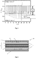
- FIG. 6 A schematic sectional view of a single cell of a total of 100 designated PEM fuel cell is in FIG. 6 to illustrate the structure and its mode of action.
- the fuel cell 100 comprises, as the core component, a membrane-electrode unit 6, which in the present case preferably has an ion exchange membrane 1, and in each case one, adjacent to one of the two flat sides of the membrane 1 electrode 2, namely an anode and a cathode.
- the ion exchange membrane 1 may be a polymer electrolyte membrane, preferably an anion exchange membrane, for example Tokuyama A201, Selemion, Fumasep, which (selectively) permits ion diffusion from the anode space into the cathode space or vice versa.
- the electrodes 2 comprise a catalytic Material that may be supported on an electrically conductive material, such as a carbon-based material.
- Each of the electrodes 2 is followed by a gas diffusion layer 3, which essentially has the task of providing a uniform distribution of the supplied operating gases via the main surfaces of the electrodes 2 or of the membrane 1.
- each bipolar plate 5 On the outer sides of each gas diffusion layer 3, a bipolar plate 5 is arranged. Bipolar plates have the task of electrically interconnecting the individual membrane-electrode units 6 of the individual cells in the stack, to cool the fuel cell stack and to supply the operating gases to the electrodes 2.
- the bipolar plates 5 also called flow field plates
- the flow fields 4 include, for example, a plurality of mutually parallel flow channels, which are incorporated in the form of grooves or grooves in the plates 5.
- each bipolar plate has on its one side an anode flux field which faces the anode 2 and on its other side a cathode flux field facing the cathode. In the present case, only one flow field 4 is shown for each of the two bipolar plates 5 shown.
- the anode flow field is supplied with a fuel, in particular hydrogen (H 2 ), while an oxygen (O 2 ) -containing operating medium, in particular air, is supplied to the cathode flow field.
- a fuel in particular hydrogen (H 2 )
- an oxygen (O 2 ) -containing operating medium in particular air
- the function of the flow fields changes, the anode field becomes the cathode field and vice versa. Therefore, it is more convenient to refer to the electrodes as the oxygen electrode and the hydrogen electrode. In this case, the reactions involving the participation of oxygen, ie the oxygen reduction and the oxygen production reaction, take place at the oxygen electrode. At the hydrogen electrode, on the other hand, the hydrogen generation and hydrogen oxidation reactions take place.
- the catalyst material according to the invention is preferably arranged on the oxygen electrode.
- FIG. 1 The reactions taking place at the electrodes are in FIG. 1 not shown.
- the electrodes catalyzed on the surface of the respective electrode release ions, which then migrate through the membrane 1.
- the oxygen electrode is a catalytic reduction of oxygen O 2 in OH hydroxide ions - taking up electrons instead.
- the hydroxide ions migrate through the anion-conducting membrane 1 and reach the hydrogen electrode.
- the supplied hydrogen H 2 reacts with the hydroxide ions OH - to form water H 2 O, wherein the hydrogen is oxidized and thus emits electrons.
- the electrons of the hydrogen electrode reaction are supplied to the oxygen electrodes via an external circuit, not shown here.
- FIG. 1 It can be seen that the product water of the fuel cell 100 is produced on the oxygen electrode side of the membrane 5.
- the catalytically coated substrate which acts as an electrode comprises a substrate and a catalyst layer applied thereto in accordance with the present invention.
- the catalyst layer may function as an oxygen electrode in a fuel cell.
- the substrate may be a membrane or a gas diffusion layer. In the embodiment shown here, the substrate is a membrane.
- the membrane may in principle be any ion exchange membrane used in fuel cell technology.
- polymer electrolyte membranes whose electrolytic conductivity is based on their moistening with water (eg Nafion®) or those which owe their conductivity to an acid bound to the polymer material or, in the case of an anion exchange membrane, from its quaternary amine, for example doped with trimethylammonium Polysulfone, resulting in quaternary benzyltrimethylammonium groups.
- polymer electrolyte membranes whose electrolytic conductivity is based on their moistening with water (eg Nafion®) or those which owe their conductivity to an acid bound to the polymer material or, in the case of an anion exchange membrane, from its quaternary amine, for example doped with trimethylammonium Polysulfone, resulting in quaternary benzyltrimethylammonium groups.
- the catalyst layer is composed at least of a catalyst material which is arranged on a carrier material. Further, it may comprise a solvent, an electrolyte and / or an electron conductor.
- the carrier material acts as an electron conductor.
- the electron conductor is electrically conductive carbon particles.
- electrically conductive carbon particles it is possible to use all carbon materials known in the field of fuel or electrolysis cells with high electrical conductivity and high surface area.
- the surface is, for example, 50 to 200 m 2 / g.
- carbon blacks, graphite or activated carbons are used. Very particular preference is given to carbon blacks having high conductivity, so-called conductive carbon blacks.
- carbon can also be used in other modifications, for example in granular form or as so-called nanotubes.
- the preferred embodiment of the catalyst material of the invention provides a novel catalyst system which can be used as a bifunctional oxygen electrode in unitized regenerative fuel cells (URFC) and metal air batteries.
- the catalyst system comprises a physical mixture of separately synthesized NiFe-layer double hydroxide (NiFe-LDH), M-doped alpha-MnO 2 (M- ⁇ -MnO 2 ) and additional carbon support.
- the proportion (weight basis) of the dopant in M- ⁇ -MnO 2 is preferably 0.2% by weight, up to 2.2% by weight.
- ⁇ -MnO 2 crystallizes in the cryptomelane structure, which is unaffected by the dopants, such as FIG. 1 shows.
- the carrier material used is preferably commercially available "carbon black", for example Vulcan XC-72R®.
- the component active for the oxidation of water is an intercalation compound, preferably NiFe-LDH.
- the molar ratio between nickel and iron is between 5: 1 and 3: 1.
- the various components are physically mixed by ultrasound.
- a suspension is prepared which contains both electrocatalysts, the carrier material, high-purity water (obtained, for example, by means of Mili-Q), isopropanol and the binder.
- the ratio (weight basis) between Mili-Q, iso -propanol and binder in the case of a slow application to a substrate is preferably 76.8% by weight: 20.0% by weight: 3.2% by weight.
- the total concentration of solids here can be in the range of 3.5 mg L -1 to 5 mg L -1 .
- water and iso-propanol are preferably present at 2% by weight and 98% by weight.
- Solid and binder are then preferably in a ratio of 7: 3 in the solvent mixture.
- the total mass of the solid may be in the range from 15,000 mg L -1 to 22,000 mg L -1 .
- the binder used is a perfluorinated sulfonic acid polymer, such as Nafion® or polysulfone, which contains quaternary benzyltrimethylammonium groups.
- NiFe-LDH is a very active and stable OER catalyst.
- Other transition-metal-based materials capable of catalyzing OER with the same activity as NiFe-LDH are nickel- or vanadium-doped cobalt ferrites (Co x (Ni / V) 3 Fe 2 O 4 ).
- the present electrocatalyst offers several over other bifunctional systems Advantages.
- the mixture of M- ⁇ -MnO 2 , NiFe-LDH, and support material in the preferred composition provides a low cost and competitive electrocatalyst that is simultaneously active for OER and ORR. While the electrochemical cleavage of water is catalyzed by NiFe-LDH, the oxygen reduction is catalyzed by the carbon-supported M- ⁇ -MnO 2 . In each case, the components mentioned are active only for OER or ORR, but not for both reactions.
- ⁇ -MnO 2 was synthesized according to a top-down approach developed by Ding et. al. ( Y. Ding, X. Shen, S. Gomez, R. Kumar, VMB Crisostomo, SL Suib and M. Aindow, Chem. Mater., 2005, 17, 5382-5389 ) has been described.
- To determine the optimal dopant for ⁇ -MnO 2 small amounts of cobalt, copper, silver, nickel and a mixture of cobalt and copper were added to the said synthesis and then tested for ORR activity. The proportion of dopant obtained was between 0.2% by weight (silver) and 2.25% by weight (copper plus cobalt).
- the crystal structure of the catalyst is not influenced by the various dopants ( FIG. 1a )).
- NiFe-LDH The second component, NiFe-LDH, was prepared using a microwave assisted synthesis to dissolve a mixture of Fe (NO) 3 .9H 2 O and Ni (OAc) 2 .4H 2 O in DMF / H 2 O, and according to a regulation by Dresp et. al ( S. Dresp, F. Luo, R. Schmack, S.de, M. Gliech and P. Strasser, Energy Environ. Sc., 2016, 9, 2020-2024 ) has been implemented.
- a three-electrode RDE setup was constructed with a platinum network as the counter electrode, a reversible hydrogen electrode (RHE) as the reference electrode, and a glassy carbon disk coated with the catalyst as the working electrode is used.
- RHE reversible hydrogen electrode
- the copper-doped manganese oxide (Cu- ⁇ -MnO 2 ) is the most active catalyst material in terms of ORR in this series.
- the electrocatalytic activities of the three-component catalyst were determined in the same manner.
- FIG. 3 a) and b) show the electrochemical activities of the three-component catalyst system with respect to ORR and OER.
- the potential difference between -3 mA cm -2 (ORR) and 10 mA cm -2 results in a total overpotential of 0.7086 V ⁇ 0.0011 V.
- the most important achievement of the catalyst material is the long-term stability, which was also evaluated in a three-electrode RDE measurement setup.
- the galvanostatic measurement was carried out at a constant current density of 4mA cm -2 for OER and -3 mA cm -2 for ORR. Between ORR and ORR relevant current density was changed every hour. The results of the stability test are in FIG. 5 shown.
Landscapes
- Chemical & Material Sciences (AREA)
- Chemical Kinetics & Catalysis (AREA)
- Electrochemistry (AREA)
- Engineering & Computer Science (AREA)
- Materials Engineering (AREA)
- General Chemical & Material Sciences (AREA)
- Metallurgy (AREA)
- Organic Chemistry (AREA)
- Composite Materials (AREA)
- Manufacturing & Machinery (AREA)
- Sustainable Development (AREA)
- Sustainable Energy (AREA)
- Life Sciences & Earth Sciences (AREA)
- Catalysts (AREA)
- Inert Electrodes (AREA)
- Electrodes For Compound Or Non-Metal Manufacture (AREA)
- Fuel Cell (AREA)
Abstract
Katalysatormaterial für eine Brennstoffzelle und ein Elektrolysesystem, sowie Herstellungsverfahren
Die Erfindung betrifft ein Mehrkomponenten-Katalysatormaterial zur Verwendung in einer Brennstoffzelle, Elektrolysesystem und einer regenerativen Brennstoffzelle bzw. reversiblen Elektrolyseurs.
Es ist vorgesehen, dass das Katalysatormaterial ein Übergangsmetalloxid, eine NiFe-Interkalationsverbindung und ein leitfähiges Trägermaterial umfasst.
Description
- Die Erfindung betrifft ein Katalysatormaterial für die Nutzung als Elektrode in einer regenerativen Brennstoffzelle bzw. einer reversiblen Elektrolysezelle mit einem solchen, sowie ein Verfahren zu dessen Herstellung.
- Die Nachfrage nach sauberen und erneuerbaren Energiespeichern und -Umwandlungssystemen für mobile und stationäre Anwendungen steigt rasant. Eine regenerative Brennstoffzelle (engl.: Unitized Regenerative Fuel Cell (URFC)), ein Hybrid aus Elektrolyseur und Brennstoffzelle, bietet die Möglichkeit, Energie aus erneuerbaren Energiequellen (Solar-/Windkraftwerke) durch elektrochemische Spaltung von Wasser in Form von molekularem Wasserstoff zu speichern und bei Bedarf in elektrische Energie rückumzuwandeln. Wasser ist das einzige Nebenprodukt dieses Prozesses. Dies bietet die Möglichkeit, produzierte Überschussenergie umweltschonend zu speichern und bei Bedarf bereitzustellen. Dieser Prozess kann die Emission von Treibhausgasen (THG) bedeutend reduzieren und so einen wichtigen Beitrag zur Energiewende darstellen. Die Leistungsfähigkeit von Elektrolyseursystemen, Brennstoffzellen oder modularen regenerativen Brennstoffzellen hängt jedoch stark von der Geschwindigkeit (Kinetik) der ablaufenden elektrochemischen Reaktionen ab. Diese Reaktionen sind zum einen die Sauerstoff umwandelnden Prozesse (Sauerstoffprozesse) Sauerstoffevolutionsreaktion (engl.: Oxygen Evolution Reaction, OER) und Sauerstoffreduktionsreaktion (engl.: Oxygen Reduction Reaction, ORR) sowie die Wasserstoff umsetzenden Prozesse (Wasserstoffprozesse) an der Wasserstoffelektrode: Wasserstoffoxidationsreaktion (engl.: Hydrogen Oxidation Reaction, HOR) und die Wasserstoffevolutionsreaktion (engl.: Hydrogen Evolution Reaction, HER). Da es sich bei den Wasserstoffreaktionen um vergleichsweise einfache Zweistufenreaktionen handelt, werden die Gesamtprozesse durch die vergleichsweise schlechte Kinetik der vierstufigen elektrochemischen Sauerstoffreaktionen limitiert.
- Aufgrund der Komplexität der genannten Sauerstoffprozesse bedarf es eines katalytischen Systems, welches OER und ORR effizient mit möglichst geringen Verlusten über lange Zeiträume katalysieren kann, um eine wettbewerbsfähige Alternative zu etablierten Energieträgern zu schaffen.
Die besten OER- und ORR-Katalysatoren unter sauren Bedingungen basieren auf Edelmetallen und deren Oxiden. Während Materialien auf der Basis von Iridium und Ruthenium am häufigsten in sauren Membran basierten Elektrolyseursystemen (engl.: Proton Exchange Membrane Water Electrolyzer, PEMWE) verwendet werden, sind Platinlegierungen die besten Katalysatoren für Brennstoffzellenanwendungen in saurem Milieu. Der Nachteil dieser Materialien ist ihr geringes Vorkommen verbunden mit hohen Kosten, wodurch eine breitere Anwendung ausgeschlossen wird. Katalysatoren, die ausschließlich auf reichlich vorkommenden Übergangsmetalloxiden oder funktionalisierten Kohlenstoffen basieren, bieten vielversprechende Alternativen für zukünftige Aufgaben. Die Charakterisierung von Übergangsmetallkatalysatoren für die OER und die ORR ist daher ein wichtiger und aktueller Forschungsschwerpunkt. - Es hat sich herausgestellt, dass vor allem Interkalationsverbindungen bestehend aus Nickel und Eisen besonders effiziente OER-Katalysatoren sind. Besonders hervorzuheben sind NiFe Verbindungen, welche als layered double hydroxide (LDH) vorliegen. Dresp et al. (S. Dresp, F. Luo, R. Schmack, S. Kühl, M. Gliech and P. Strasser, Energy Environ. Sc., 2016, 9, 2020-2024) zeigten, dass NiFe-LDH als OER-aktive Komponente in einem bifunktionellen Zweikomponenten-Katalysatorsystem geeignet ist. Leider zeigte das benannte System enorme Aktivitätsverluste während elektrochemischer Belastungstests, die auf die durch die hohen OER Potentiale verursachte Degradation der ORR-aktiven kohlenstoffbasierten Spezies zurückzuführen ist. Die Aktivität der OER-aktiven Komponente wurde dadurch nicht eingeschränkt. Für einen bifunktionellen Katalysator für die Anwendung in einer regenerativen Brennstoffzelle wird neben NiFe-LDH eine zweite hinreichend stabile ORR-aktive Komponente benötigt, da NiFe-LDH keine hinreichende ORR Aktivität besitzt.
- Manganoxide, besonders Perovskite (Mn2O3) und Cryptomelan-Typ Oxide (MnO2) zeigen ORR-Aktivitäten in alkalischen Medien, vergleichbar mit kommerziellem Pt/C. Die Nachteile dieser Oxide resultieren aus der Größe der Materialien kombiniert mit einer geringen Oberfläche, sowie einer schlechten elektrischen Leitfähigkeit. Diese Nachteile erfordern Modifikationen des Metalloxids und die Verwendung eines geeigneten, leitfähigen Trägermaterials mit großer Oberfläche. Die gebräuchlichsten Trägermaterialien sind "Carbon Blacks" wie Vulcan XC-72R, Graphen oder Carbon Nanotubes (CNT). Derartige Trägermaterialien führen aber im Hinblick auf dessen Kohlenstoffkorrosion, welche bei OER relevanten-Potentialen auftreten kann, zu einer signifikanten Destabilisierung des Katalysatormaterials. Entsprechend sind solche Katalysatorsysteme in einem bifunktionellen Sauerstoff-Elektrodensystem durch geringe Langzeitstabilitäten eingeschränkt.
Die Kombination eines auf die Katalyse der ORR spezialisierten Materials mit einem auf die Katalyse der OER spezialisierten Materials führt zu einem neuen Katalysatorsystem, welches idealerweise die vorteilhaften katalytischen Eigenschaften des jeweils spezialisierten Materials zeigt. Allerdings werden in der Regel auch die Nachteile der jeweiligen Materialien importiert. Dadurch ist es extrem schwierig zwei Materialien zu finden, welche eine der genannten Reaktionen aktiv katalysieren und unter den gänzlich anderen Bedingungen der Rückreaktion eine ausreichende Stabilität aufweisen. Dies ist unseres Wissens nach dem Stand der Technik noch nicht gelungen. - Der Erfindung liegt nun die Aufgabe zugrunde, die Probleme des Standes der Technik zu vermeiden. Insbesondere soll ein Katalysatormaterial für eine Elektrode in einer Brennstoffzelle, einem Elektrolyseur oder einer Metall-Luft-Batterie bereitgestellt werden, die sowohl eine sauerstoffumsetzende Reaktion, als auch eine sauerstofferzeugende Reaktion katalysiert. Darüber hinaus sollte die bereitgestellte Elektrode eine hohe Langzeitstabilität, insbesondere im Vergleich zu herkömmlichen Elektroden aufweisen.
- Diese Aufgabe wird durch ein Katalysatormaterial für eine regenerative Brennstoffzelle oder reversiblen Elektrolyseur, eine Elektrode bzw. eine regenerative Brennstoffzelle mit einem solchen sowie ein Verfahren zu deren Herstellung mit den Merkmalen der unabhängigen Ansprüche gelöst.
- Somit betrifft ein erster Aspekt der Erfindung ein Katalysatormaterial für eine regenerative Brennstoffzelle oder reversiblen Elektrolyseur, umfassend ein Mehrkomponentensystem aufweisend ein dotiertes Übergangsmetalloxid, eine NiFe-Interkalationsverbindung sowie ein leitfähiges kohlenstoffhaltiges Trägermaterial.
- Die vorliegende Erfindung stellt ein bifunktionelles Katalysatormaterial zur Verfügung, das in der Lage ist, die Sauerstoffreduktionsreaktion (ORR) und die Sauerstoffentstehungsreaktion (OER) in modularen regenerativen Brennstoffzellen (URFC), reversiblen Elektrolyseuren oder Metallluftbatterien gleichermaßen zu katalysieren. Das Material umfasst im Gegensatz zu herkömmlichen Katalysatormaterialien für Brennstoffzellen und Elektrolyseuren zwei Elektrokatalysatoren, die jeweils selektiv eine der Sauerstoffreaktionen an einer Sauerstoffelektrode katalysieren. Mit anderen Worten, durch die vorliegende Kombination beider Elektrokatalysatoren ist die Oxidation von Wasser und die Reduktion von Sauerstoff gleicharmaßen aktiv. Das zusätzliche Trägermaterial verbessert die Gesamtleitfähigkeit und steigert die Aktivität.
Das Kupfer dotierte Manganoxid katalysiert selektiv die Reduktion von Sauerstoff (ORR), wohingegen die NiFe-Interkalationsverbindung selektiv die Sauerstoffentstehungsreaktion (OER) katalysiert. Überraschenderweise wird durch die Kombination der beiden spezialisierten Katalysatorbestandteile, die jeweilige Selektivität und Aktivität nicht signifikant beeinträchtigt. - Die bifunktionelle Aktivität des erfindungsgemäße Katalysatormaterials ist bemerkenswert gut. Im Gegensatz zum üblichen Ansatz der Aktivitätsmaximierung durch Vergrößerung der Oberfläche (sehr kleine Nanopartikel) weist das erfindungsgemäße Katalysatormaterial bevorzugt vergleichsweise große Partikel und damit kleine Oberflächen auf. Das Manganoxid formt vorzugsweise rutenförmige Partikel, welche eine durchschnittliche Partikelgröße vorzugsweise 100 x 15 x 15 nm aufweisen und die NiFe-Interkalationsverbindung formt bevorzugt kleine dünne Plättchen mit einem Durchmesser im Bereich von 10-500 nm. Übliche Edelmetall basierte Referenzkatalysatoren weisen einen Durchmesser von 1 - 5 nm auf. Somit sind beide Materialien vergleichbar große Elektrokatalysatoren. Außerdem haben NiFe-Interkalationsverbindungen die Tendenz, die aktive Oberfläche durch Abdeckung der reaktiven Grenzfläche des Katalysators zu minimieren. Daher sind die gleichzeitig hohen ORR- und OER-Aktivitäten überraschend. Die Stabilität des erfindungsgemäßen Katalysatormaterials ist ebenso erstaunlich, da eine Kohlenstoffkomponente enthalten ist. Aufgrund der erwähnten Kohlenstoffkorrosion führt das in den meisten Fällen zu einer drastischen Verschlechterung der Aktivität über längere Zeiträume, während sie in dem erfindungsgemäßen System erhalten bleibt.
- Demnach zeigte sich, dass das erfindungsgemäße Katalysatormaterial eine überraschend geringe Degradation durch Katalysatorkorrosion, insbesondere eine geringe Neigung zur Kohlenstoffkorrosion im Trägermaterial aufweist. Dies führt zu einer deutlich höheren Langzeitstabilität des Katalysatormaterials verglichen zu bekannten Systemen.
- In bevorzugter Ausgestaltung der Erfindung ist vorgesehen, dass das dotierte Übergangsmetalloxid ein mit einem Dotanden M dotiertes Manganoxid ist. Manganoxid ist als Basismaterial besonders kostengünstig und zeigt insbesondere als α-Manganoxid, beispielsweise im Cryptonmelan-Typ, bemerkenswerte ORR-Aktivitäten. Somit ist es besonders bevorzugt, dass das Übergangsmetalloxid der Formel M-α-MnO2 entspricht.
- Der Dotand M ist ausgewählt aus der Gruppe Nickel, Kupfer, Silber und/oder Kobalt. Diese Gruppe der Dotanden erwies sich als besonders geeignet, um die Aktivität des Katalysatormaterials bei Sauerstoffreduktionsreaktionen zu erhöhen.
- In weiterer bevorzugter Ausgestaltung der Erfindung ist vorgesehen, dass der Dotand zu einem Gewichtsanteil zwischen 0,1-2,5 Gew.-%,bezogen auf das Manganoxid, enthalten ist. Eine Dotierung des Übergangsmetalloxids in diesen Bereichen zeigte sich insbesondere bei der oben genannten Gruppe möglicher Dotanden als vorteilhaft in Bezug auf die Aktivität und die Stabilität des dotierten Übergangsmetalloxids bei gleichzeitiger Maximierung der selektiven Katalyse der Sauerstoffreduktionsreaktion.
- Mit besonderem Vorteil liegt die NiFe-Interkalationsverbindung als Layered Double Hydroxide (LDH) vor. NiFe-LDH zeigt eine hohe Aktivität bei der Katalyse von Sauerstoffentwicklungsreaktionen und zeichnet sich darüber hinaus durch seine hohe Selektivität und Stabilität aus.
- LDH sind eine Klasse ionischer Feststoffe, die durch eine Schichtstruktur mit der generischen Abfolge [AcBZAcB]n ausgezeichnet ist. Dabei definiert c Schichten von Metallkationen, wobei A und B Schichten von Hydroxid (HO-eine Ionen) und Z Schichten anderer eine Ionen und neutrale Moleküle (wie beispielsweise Wasser) darstellen. Seitliche Versätze zwischen den Lagen können zu längeren Wiederholungsperioden führen. Die interkalierten Anionen (Z) sind schwach gebunden und oft austauschbar. Vorliegend sind Eisen und Nickel divalente und trivalente Kationen, die in einer positiven Schicht c zwischen anionischen oder neutralen Hydroxidschichten angeordnet sind. Hierbei handelt es sich um eine Interkallationsverbindung des Hydrotalcit-Typs. Besonders bevorzugt sind Nickel und Eisen im molaren Verhältnis von 3 : 1 bis 5 : 1 in der NiFe-Interkalationsverbindung vorliegend. Die angegebenen Anteile beziehen sich auf molare Anteile gemessen über ICP-OES. Da allerdings die molaren Massen sehr ähnlich sind, sind die Unterschiede zu den Gewichtsanteilen gering.
- In weiterer bevorzugter Ausgestaltung der Erfindung ist vorgesehen, dass das leitende Trägermaterial auszuwählen ist aus partikulärem Kohlenstoff, so genanntem Carbon Black, Graphen, nanostrukturiertem Kohlenstoff, Kohlenstoffnanoröhrchen und/oder karbonisiertem Trägermaterial. Diese Materialien zeigen optimale elektrische Leitfähigkeiten und justierbare Oberflächengrößen und sind daher als Trägermaterial für das Übergangsmetalloxid und/oder die Interkalationsverbindung besonders geeignet. Im erfindungsgemäßen Katalysatormaterial dient das Trägermaterial insbesondere als Substrat für das Übergangsmetalloxid, welches sich demgemäß auf der Oberfläche des Trägermaterials anlagert. Damit werden die Nachteile der meisten Übergangsmetalloxide, insbesondere der Cryptomelane, die sich in kleinen Dimensionen und damit verbunden niedriger Oberfläche zeigen, überwunden bzw. neutralisiert. Zudem wird eine Aggregation der katalytisch aktiven Substanz, ebenso wie ein Austrag dieser aus dem System, verhindert.
- Mit besonderem Vorteil liegt ein Gewichtsverhältnis zwischen Übergangsmetalloxid, Interkallationsverbindung und Trägermaterial im Bereich von 1:1:1 bis 3:3:1. In diesem Bereich konnte die oben bereits beschriebene vergleichsweise geringe aktive Oberfläche, insbesondere eine geringe freie Oberfläche des Trägermaterials, im erfindungsgemäßen Katalysatormaterial mit den sich daraus ergebenden unerwarteten Vorteilen bezüglich Langzeitstabilität des Katalysatormaterials bei Verwendung in einer Elektrode, besonders gut generiert werden.
- Ein weiterer Aspekt der Erfindung betrifft eine Elektrode, insbesondere eine Sauerstoffelektrode für eine Brennstoffzelle, die das erfindungsgemäße Katalysatormaterial aufweist. Ferner betrifft die Erfindung eine Brennstoffzelle aufweisend eine lonenaustauschmembran, die zumindest einseitig mit dem erfindungsgemäßen Katalysatormaterial beschichtet ist.
- Darüber hinaus betrifft die Erfindung ein Verfahren zum Herstellen des erfindungsgemäßen Katalysatormaterials. Das erfindungsgemäße Verfahren umfasst das Bereiten einer Mischung aus dem dotierten Übergangsmetalloxid, der Interkallationsverbindung sowie dem leitfähigen Trägermaterial durch physikalische Vermengung der Ausgangsmaterialien in Pulver- oder partikulärer Form, wobei die Partikel bevorzugt Nanopartikel sind, also mittlere Partikelgrößen im Bereich von 1 bis 100 nm aufweisen. Zum Bereiten einer Katalysatortinte, in Form einer Katalysatordispersion, wird die Mischung unter Zugabe von hochreinem Wasser, iso-Propanol sowie optional einem Bindemittel suspendiert. Die Suspension wird vorzugsweise durch Ultraschallanwendungen unterstützt. Das hochreine Wasser hat einen Wiederstand von mindestens 17 MΩ, vorzugsweise 18,2 MΩ oder mehr.
Anschließend wird die erhaltene Katalysatortinte durch übliche Verfahren auf einem Substrat aufgetragen. Nachdem die Lösungsmittel abgedampft sind, verbleibt das erfindungsgemäße Katalysatormaterial mit Binder auf dem Substrat. - Als Bindemittel wird bevorzugt ein perfluoriertes Sulfonsäurepolymer, insbesondere Nafion®, eingesetzt. Im Vergleich zu anderen Bindemitteln haben diese den Vorteil, dass es ionische Eigenschaften aufweisen und somit die Leitfähigkeit des Katalysatormaterials nicht herabsetzen. Darüber hinaus zeichnen sich perfluorierte Sulfonsäurepolymere durch hohe Betriebstemperaturen im Vergleich zu anderen Polymeren aus.
- Im Falle langsamer Verfahren der Auftragung der Katalysatortinte auf ein Substrat sind folgenden Verhältnisse bevorzugt. Mit besonderem Vorteil ist Wasser zu 70-80 Gew.-%, iso-Propanol mit 15-35 Gew.-% und Bindemittel von 0-5 Gew.-% insbesondere von 2-5 Gew.-% bezogen auf die Summe der Komponenten Wasser, iso-Propanol und Bindemittel in der Suspension enthalten. Besonders bevorzugt liegen sie in einem Verhältnis von 76,8 : 20 : 3,2 Gew.-% vor. Die Lösungsmittelverhältnisse sowie Verhältnisse zwischen Katalysator und Bindemittel können auf ein schnelleres Beschichtungsverfahren wie folgt angepasst werden. Mit besonderem Vorteil liegt Wasser von 0.5-5 Gew.-%, iso-Propanol mit 95-99.5 Gew.-%, bezogen auf die Summe der Komponenten Wasser und iso-Propanol vor. Katalysator und Bindemittel werden in einem Verhältnis zwischen 5 : 3 und 7 : 3 zu dem genannten Lösungsmittelgemisch hinzugefügt. Innerhalb der oben angegebenen Anteilsbereiche zeigen die bereitgestellten Katalysatortinten eine besonders gleichmäßige Verteilung und gute Suspensionsfähigkeit der Partikel (Übergangsmetalloxid, Interkallationsverbindung, Trägermaterial), sowie einen optimalen Kompromiss aus zügigem und schonendem Abdampfen der Lösungsmittel. Das vorliegende Verhältnis zwischen organischer Komponenten und Wasser zeigte eine hohe physikalische Stabilität und Haftung des Katalysatormaterials bzw. der Katalysatorschicht.
- Das mit dem erfindungsgemäßen Katalysatormaterial beschichtete Substrat findet vorzugsweise als Elektrode, insbesondere als Sauerstoffelektrode, in einer Brennstoffzelle, einem Elektrolyseur einer Batterie oder einer regenerativen Brennstoffzelle bzw. reversiblen Elektrolyseur Verwendung.
- Weitere bevorzugte Ausgestaltungen der Erfindung ergeben sich aus den übrigen, in den Unteransprüchen genannten Merkmalen.
- Die verschiedenen in dieser Anmeldung genannten Ausführungsformen der Erfindung sind, sofern im Einzelfall nicht anders ausgeführt, mit Vorteil miteinander kombinierbar.
- Die Erfindung wird nachfolgend in Ausführungsbeispielen anhand der zugehörigen Zeichnungen erläutert. Es zeigen:
- Figur 1
- XRD-Diffraktogramm von mit Kobalt, Nickel, Kupfer und Silber dotiertem alpha Mangan(IV)oxid sowie eine pures alpha Mangan(IV)oxid,
- Figur 2
- eine graphische Gegenüberstellung elektrochemischer RDE-Messungen einiger mit Kobalt, Nickel, Kupfer und Silber dotiertem alpha Mangan(IV)oxid,
- Figur 3
- eine graphische Darstellung zyklischer Voltammogramme des erfindungsgemäßen Katalysatormaterials im Vergleich mit den Einzelkomponenten, sowie edelmetallbasierten Referenzkatalysatoren,
- Figur 4
- eine graphische Darstellung zyklischer Voltammogramme nach elektrochemischer Stabilitätstestung des erfindungsgemäßen Katalysatormaterials im Vergleich mit den Einzelkomponenten, sowie edelmetallbasierten Referenzkatalysatoren,
- Figur 5
- eine graphische Darstellung eines galvanostatischen Stabilitätstests an einer rotierenden Scheibenelektrode,
- Figur 6
- eine schematische Schnittansicht einer modular regenerierenden Brennstoffzelle (URFC) in einer bevorzugten Ausgestaltung der Erfindung.
-
Figur 1 zeigt a) XRD-Diffraktogramme verschiedener Kryptomelan-Mangan-Oxide (α-MnO2) und modifizierte Manganoxide vom Kryptomelan-Typ (M-α-MnO2, M = Cu, Ni, Ag, Co). Die Kristallstruktur des resultierenden Manganoxids wird durch die Metalldotierungen nicht beeinflusst. Dies lässt den Schluss zu, dass die Menge der Dotierstoffe durch die eingesetzte Synthese drastisch erhöht werden kann. In Teil b) derFigur 1 sind XRD-Diffraktogramme der einzelnen Komponenten des Drei-Komponenten-Systems, sowie das Drei-Komponenten-System dargestellt. - Ergebnisse elektrochemischer RDE Messungen in Sauerstoff gesättigter 0,1 M KOH, bei 5 mV s-1, 1600 U/min und einer Katalysatorbeladung von 203,72 µg cm-2 sind in
Figur 2 gezeigt. Die Figur zeigt die ORR-Aktivitäten verschiedener Manganoxide des Kryptomelan-Typs (M-α-MnO2, M = Cu, Ni, Ag, Co). Wie inFigur 2 dargestellt, hat Cu-α-MnO2 das positivste Potential bei -3 mA cm-2 und die höchsten Diffusionsgrenzströme, daher kann Cu-α-MnO2 unter den untersuchten Materialien als das aktivste Material angesehen werden und wird für die weiterführenden Messung des erfindungsgemäßen Katalysators zugrunde gelegt. - In
Figur 3 sind zwei Diagramme gezeigt, welche a) ORR- und b) OER-Aktivitäten von NiFe-LDH, Pt/C-Ir/C, Cu-α-MnO2/Carbon und physikalisch gemischtem Cu-α-MnO2/Carbon/NiFeLDH zeigen. Den Graphen ist zu entnehmen, dass das erfindungsgemäße Übergangsmetalloxidbasierte System den als Referenz verwendeten kommerziellen Katalysator in Bezug auf ORRsowie OER-Aktivität übertrifft. Die ORR-Aktivität des Manganoxids wird durch die Zugabe von NiFe-LDH nur geringfügig beeinflusst, während die OER-Aktivität drastisch gesteigert wird. -
Figur 4 zeigt a) ORR und b) OER-Aktivitäten von Cu-α-MnO2/Carbon, kommerziellem Pt/C-Ir/C und Cu-α-MnO2/Carbon/NiFe-LDH nach elektrochemischer Belastung. Die Stabilität des Übergangsmetallkatalysators übertrifft die Stabilität des kommerziellen Edelmetall-Referenzkatalysators. Zudem zeigt sich in einem einfachem Vergleich, dass NiFe-LDH die Stabilität des erfindungsgemäßen Drei-Komponenten-Katalysators erheblich verbessert. Während die Aktivität des NiFe-LDH freiem Cu-α-MnO2/Carbon drastisch abnimmt, ist die Aktivität des NiFe-LDH haltigem Systems weniger stark beeinflusst. Daher wird von einer abschirmenden Wirkung von NiFe-LDH ausgegangen. -
Figur 5 zeigt eine graphische Darstellung galvanostatischer Stabilitätsmessungen an einer rotierenden Scheibenelektrode in einer sauerstoffgesättigtem 0,1 M KOH Lösung des vorgestellten Cu-α-MnO2/Carbon/NiFe-LDH, einem kommerziellem Referenzkatalysator und einem Übergangsmetallbasiertem Vergleichssystem (Daten von NiFe-LDH/PANI aus Referenz). Der Strom wurde für die Sauerstoffreduktions-Reaktion konstant bei -3 mA cm-2 und für die Sauerstoff-Evolutionsreaktion konstant bei 4 mA cm-2 gehalten. Im Gegensatz zum Übergangsmetallbasiertem Vergleichssystem und dem auf Edelmetall basierendem Referenzkatalysator bleibt die Gesamtaktivität über mehr als 18 Zyklen alternierenden OER- und ORR-Potentialzyklen stabil erhalten. - Eine schematische Schnittansicht einer Einzelzelle einer insgesamt mit 100 bezeichneten PEM-Brennstoffzelle ist in
Figur 6 zur Erläuterung des Aufbaus und ihrer Wirkungsweise dargestellt. - Die Brennstoffzelle 100 umfasst als Kernkomponente eine Membran-Elektroden-Einheit 6, welche vorliegend bevorzugt eine lonenaustauschmembran 1 aufweist sowie jeweils eine, an eine der beiden Flachseiten der Membran 1 anschließende Elektrode 2, nämlich eine Anode sowie eine Kathode. Bei der lonenaustauschmembran 1 kann es sich um eine Polymerelektrolytmembran, bevorzugt Anionenaustauschmembran, beispielsweise Tokuyama A201, Selemion, Fumasep handeln, welche (selektiv) eine lonendiffusion vom Anodenraum in den Kathodenraum oder umgekehrt zulässt. Die Elektroden 2 umfassen ein katalytisches Material, das auf einem elektrisch leitfähigen Material, beispielsweise einem kohlenstoffbasierten Material, geträgert vorliegen kann.
- An die Elektroden 2 schließt jeweils eine Gasdiffusionsschicht 3 an, der im Wesentlichen die Aufgabe einer gleichmäßigen Verteilung der zugeführten Betriebsgase über die Hauptflächen der Elektroden 2, beziehungsweise der Membran 1, zukommt.
- An den Außenseiten jeder Gasdiffusionsschicht 3 ist eine Bipolarplatte 5 angeordnet. Bipolarplatten haben die Aufgabe, die einzelnen Membran-Elektroden-Einheiten 6 der Einzelzellen im Stapel elektrisch miteinander zu verschalten, den Brennstoffzellenstapel zu kühlen sowie die Betriebsgase den Elektroden 2 zuzuführen. Zu letzterem Zweck weisen die Bipolarplatten 5 (auch Flussfeldplatten genannt) Flussfelder 4 auf. Die Flussfelder 4 umfassen beispielsweise eine Vielzahl parallel zueinander angeordneter Strömungskanäle, die in Form von Rinnen oder Nuten in die Platten 5 eingearbeitet sind. Üblicherweise weist jede Bipolarplatte auf ihrer einen Seite ein Anodenflussfeld auf, das der Anode 2 zugewandt ist, und auf ihrer anderen Seite ein der Kathode zugewandtes Kathodenflussfeld. Vorliegend ist für jede der zwei dargestellten Bipolarplatten 5 jeweils nur ein Flussfeld 4 abgebildet.
- Im Betrieb als Brennstoffzelle wird dem Anodenflussfeld ein Brennstoff, insbesondere Wasserstoff (H2) zugeführt, während dem Kathodenflussfeld ein Sauerstoff (O2) enthaltenes Betriebsmittel, insbesondere Luft zugeführt wird.
- Im Betrieb als reversible Brennstoffzelle ändert sich die Funktion der Flussfelder, das Anodenfeld wird zum Kathodenfeld und umgekehrt. Daher ist es zweckmäßiger, die Elektroden als Sauerstoffelektrode und Wasserstoffelektrode zu bezeichnen. Dabei finden an der Sauerstoffelektrode die Reaktionen unter Beteiligung von Sauerstoff, also die Sauerstoffreduktions- und die Sauerstofferzeugungsreaktion statt. An der Wasserstoffelektrode hingegen finden die Wasserstofferzeugungs- und Wasserstoffoxidationsreaktion statt.
- Da die an der Wasserstoffelektrode stattfindenden Reaktionen weniger komplex und leichter zu katalysieren sind, ist das erfindungsgemäße Katalysatormaterial bevorzugt auf der Sauerstoffelektrode angeordnet.
- Die an den Elektroden stattfindenden Reaktionen sind in
Figur 1 nicht dargestellt. Die an der Oberfläche der jeweiligen Elektrode katalysierten Elektroden setzen Ionen frei, welche dann durch die Membran 1 migrieren. Im Falle einer Brennstoffzellenreaktion bedeutet das, dass an der Sauerstoffelektrode eine katalytische Reduktion von Sauerstoff O2 in Hydroxidionen OH- unter Aufnahme von Elektronen statt. Die Hydroxidionen migrieren durch die Anionen leitende Membran 1 und erreichen die Wasserstoffelektrode. Dort reagiert der zugeführte Wasserstoff H2 mit den Hydroxidionen OH- zu Wasser H2O, wobei der Wasserstoff oxidiert wird und somit Elektronen abgibt. Die Elektronen der Wasserstoffelektrodenreaktion werden über einen äußeren, hier nicht dargestellten Stromkreis den Sauerstoffelektroden zugeführt. AusFigur 1 ist ersichtlich, dass das Produktwasser der Brennstoffzelle 100 auf der Sauerstoffelektrodenseite der Membran 5 anfällt. - Das katalytisch beschichtete Substrat, welches als Elektrode wirkt, umfasst ein Substrat sowie eine darauf aufgebrachte Katalysatorschicht gemäß der vorliegenden Erfindung. Die Katalysatorschicht kann als Sauerstoffelektrode in einer Brennstoffzelle fungieren. Das Substrat kann eine Membran oder eine Gasdiffusionsschicht sein. In der hier dargestellten Ausführungsform handelt es sich bei dem Substrat um eine Membran. Bei der Membran kann es sich prinzipiell um eine beliebige, in der Brennstoffzellentechnik verwendete lonenaustauschermembran handeln. Hierzu zählen etwa Polymerelektrolytmembrane, deren elektrolytische Leitfähigkeit auf ihrer Befeuchtung mit Wasser beruht (z. B. Nafion®), oder solche, die ihre Leitfähigkeit einer an das Polymermaterial gebundenen Säure oder im Falle von Anionenaustauschmembran von dessen quaternärem Amin verdanken, beispielsweise mit Trimethylammonium gedopten Polysulfon, sodass quaternäre Benzyltrimethylammonium Gruppen entstehen.
- Die Katalysatorschicht setzt sich zumindest aus einem Katalysatormaterial zusammen, welches auf einem Trägermaterial angeordnet ist. Ferner kann sie ein Lösungsmittel, einen Elektrolyten und/oder einen Elektronenleiter umfassen.
- Das Trägermaterial fungiert als Elektronenleiter. Im Allgemeinen handelt es sich bei dem Elektronenleiter um elektrisch leitfähige Kohlenstoffpartikel. Als elektrisch leitfähige Kohlenstoffpartikel können alle auf dem Gebiet der Brennstoff- beziehungsweise Elektrolysezellen bekannten Kohlenstoffmaterialien mit hoher elektrischer Leitfähigkeit und großer Oberfläche eingesetzt werden. Die Oberfläche beträgt beispielsweise 50 bis 200 m2/g. Bevorzugt werden Ruße, Graphit oder Aktivkohlen verwendet. Ganz besonders bevorzugt sind Ruße mit hoher Leitfähigkeit, sogenannte Leitfähigkeitsruße. Darüber hinaus kann Kohlenstoff auch in anderen Modifikationen, beispielsweise in granularer Form oder als sogenannte Nanotubes eingesetzt werden.
- Die bevorzugte Ausführungsform des erfindungsgemäßen Katalysatormaterials stellt ein neuartiges Katalysatorsystem zur Verfügung, das als bifunktionelle Sauerstoffelektrode in Unitized Regenerative Fuel Cells (URFC) und Metallluftbatterien eingesetzt werden kann. Das Katalysatorsystem umfasst ein physikalisches Gemisch aus getrennt synthetisiertem NiFe-Schicht-Doppelhydroxid (NiFe-LDH), M-dotiertem alpha-MnO2 (M-α-MnO2) und zusätzlichem Kohlenstoffträger.
- Insbesondere M-α-MnO2 (M = Nickel, Kupfer, Silber oder Kobalt) ist die für ORR katalytisch wirkende Komponente. Der Anteil (Gewichtsbasis) des Dotierstoffes in M-α-MnO2 liegt bevorzugt bei 0,2 Gew.-%, bis zu 2,2 Gew. %. α-MnO2 kristallisiert in der Kryptomelanstruktur, die von den Dotierstoffen nicht beeinflusst wird, wie
Figur 1 zeigt. Als Trägermaterial wird bevorzugt handelsüblicher "Carbon Black", beispielsweise Vulcan XC-72R® verwendet. - Die für die Oxidation von Wasser aktive Komponente ist eine Interkallationsverbindung, bevorzugt NiFe-LDH. Das molare Verhältnis zwischen Nickel und Eisen liegt dabei zwischen 5 : 1 bis 3 : 1. Um den Elektrokatalysator zu erhalten, der in der Lage ist, die genannten Reaktionen zu katalysieren, werden die verschiedenen Komponenten physikalisch durch Ultraschall vermischt. Dazu wird eine Suspension hergestellt, die beide Elektrokatalysatoren, das Trägermaterial, hochreines Wasser (beispielsweise mittels Mili-Q erhalten), iso-Propanol und das Bindemittel enthält. Das Verhältnis (Gewichtsbasis) zwischen Mili-Q, iso-Propanol und Bindemittel beträgt im Falle einer langsamen Auftragung auf ein Substrat bevorzugt 76,8 Gew.-%: 20,0 Gew.-%: 3,2 Gew.-%. Die Gesamtkonzentration der Feststoffe kann hier im Bereich von 3,5 mg L-1 bis 5 mg L-1 liegen. Im Falle einer schnellen Auftragung liegen Wasser und iso-Propanol bevorzugt mit 2 Gew.-% und 98 Gew.-% vor. Feststoff und Bindemittel liegen dann bevorzugt in einem Verhältnis von 7 : 3 in dem Lösungsmittelgemisch vor. Die Gesamtmasse des Feststoffs kann hier in einem Bereich von 15000 mg L-1 bis 22000 mg L-1 liegen. Das verwendete Bindemittel ist ein perfluoriertes Sulfonsäurepolymer wie Nafion® oder Polysulfon, welches quaternäre Benzyltrimethylammonium-Gruppen enthält.
- α-MnO2 allein ist kein ausreichend aktiver und stabiler Katalysator für die ORR. Das Aufbringen von α-MnO2 auf Kohlenstoff, insbesondere Vulcan XC-72R und die Dotierung von α-MnO2 , insbesondere mit Kupfer liefert ein Material, das ein konkurrenzfähiger ORR-Katalysator ist. NiFe-LDH ist ein sehr aktiver und stabiler OER-Katalysator. Andere Materialien auf der Basis von Übergangsmetallen, die in der Lage sind, OER mit der gleichen Aktivität wie NiFe-LDH zu katalysieren, sind Nickel- oder Vanadium-dotierte Cobaltferrite (Cox(Ni/V)3Fe2O4). Der vorliegende Elektrokatalysator bietet gegenüber anderen bifunktionellen Systemen mehrere Vorteile. Es ist ein sehr kosteneffizientes System, verglichen mit Elektrokatalysatoren auf der Basis von Edelmetallen wie Pt/C-Ir/C, die ähnliche OER- und ORR-Aktivitäten erzielen. Im Vergleich zu anderen ORR-Katalysatoren auf der Basis von Übergangsmetallen und Kohlenstoffmaterialien ist die Synthese der ORR-aktiven Komponente einfach, schnell, energieeffizient und leicht skalierbar. Der größte Vorteil des hier vorgestellten Dreikomponenten-Systems ist die außerordentliche Stabilität. Während die Aktivität von Systemen wie NiFe-LDH/PANI oder Pt/C-Ir/C während andauernder elektrochemischer Belastung signifikant abnimmt, bleibt die Aktivität des erfindungsgemäßen Katalysatormaterials trotz der Kohlenstoffkomponente intakt (
Figur 4 ). - Die Mischung aus M-α-MnO2, NiFe-LDH und Trägermaterial in der bevorzugten Zusammensetzung liefert einen kostengünstigen und wettbewerbsfähigen Elektrokatalysator, der gleichzeitig für OER und ORR aktiv ist. Während die elektrochemische Spaltung von Wasser durch NiFe-LDH katalysiert wird, wird die Sauerstoffreduktion durch das kohlenstoffgeträgerte M-α-MnO2 katalysiert. Dabei sind die genannten Komponenten jeweils nur für OER oder ORR aktiv, nicht aber für beide Reaktionen.
- Im folgenden sind Beispiele zur Darstellung des erfindungsgemäßen Katalysatormaterials angegeben.
- α-MnO2 wurde nach einem Top-Down-Ansatz synthetisiert, der von Ding et. al. (Y. Ding, X. Shen, S. Gomez, R. Kumar, V. M. B. Crisostomo, S. L. Suib and M. Aindow, Chem. Mater., 2005, 17, 5382-5389) beschrieben wurde. Zur Bestimmung des optimalen Dotierstoffes für α-MnO2 wurden kleine Mengen Kobalt, Kupfer, Silber, Nickel und ein Gemisch aus Kobalt und Kupfer der genannten Synthese zugesetzt und anschließend hinsichtlich der ORR-Aktivität getestet. Der erhaltene Anteil des Dotierstoffes lag zwischen 0,2 Gew.-% (Silber) und 2,25 Gew.-% (Kupfer plus Kobalt). Die Kristallstruktur des Katalysators wird durch die verschiedenen Dotierstoffe nicht beeinflusst (
Figur 1a )). - Die zweite Komponente, NiFe-LDH, wurde unter Verwendung einer mikrowellenunterstützten Synthese hergestellt, wobei eine Mischung aus Fe(NO)3 x 9 H2O und Ni(OAc)2 x 4 H2O in DMF/H2O gelöst wurde und nach einer Vorschrift von Dresp et. al (S. Dresp, F. Luo, R. Schmack, S. Kühl, M. Gliech and P. Strasser, Energy Environ. Sc., 2016, 9, 2020-2024) umgesetzt wurde.
- Zur Bestimmung der ORR- und OER-Aktivitäten der reinen und der gemischten Komponenten wurde ein Drei-Elektroden-RDE-Aufbau mit einem Platinnetz als Gegenelektrode, einer reversiblen Wasserstoffelektrode (RHE) als Referenzelektrode und einer glasartigen Kohlenstoffscheibe, die mit dem Katalysator als Arbeitselektrode beschichtet ist, verwendet. Wie in
Figur 2 ) dargestellt, ist das Kupfer dotierte Manganoxid (Cu- α-MnO2) das aktivste Katalysatormaterial hinsichtlich ORR dieser Reihe. Die elektrokatalytischen Aktivitäten des Dreikomponenten-Katalysators wurden auf die gleiche Weise bestimmt. InFigur 3 a) und b) sind die elektrochemischen Aktivitäten des Dreikomponenten-Katalysatorsystems hinsichtlich ORR sowie OER dargestellt. Die Potentialdifferenz zwischen -3 mA cm-2 (ORR) und 10 mA cm-2 resultiert in einem Gesamtüberpotential von 0,7086 V ± 0,0011 V. - Die wichtigste Errungenschaft des Katalysatormaterials stellt die Langzeitstabilität dar, die ebenfalls in einem Dreielektroden-RDE-Messaufbau evaluiert wurde. Die galvanostatische Messung wurde bei einer konstanten Stromdichte von 4mA cm-2 für OER und -3 mA cm-2 für ORR durchgeführt. Zwischen ORR und ORR relevanter Stromdichte wurde stündlich gewechselt. Die Ergebnisse der Stabilitätstestung sind in
Figur 5 dargestellt. -
- 100
- kombinierte Brennstoffzelle
- 1
- Membran
- 2
- Elektrode
- 3
- Gasdiffusionsschicht - GDL
- 4
- Flussfeld
- 5
- Bipolarplatte - BPP
- 6
- Membran-Elektroden-Einheit - MEA
- 10
- Flussrichtung Betrieb Brennstoffzelle
- 11
- Flussrichtung Betrieb reversible Brennstoffzelle
Claims (12)
- Katalysatormaterial für eine Brennstoffzelle, umfassend ein Mehrkomponentensystem aufweisend ein mit einem Dotanden M dotiertes Übergangsmetalloxid, eine NiFe-Interkalationsverbindung, welche mittelbar oder unmittelbar in einem leitfähigen kohlenstoffhaltigen Trägermaterial angeordnet sind.
- Katalysatormaterial nach Anspruch 1, dadurch gekennzeichnet, dass das dotierte Übergangsmetalloxid ein mit einem Dotanden M dotiertes Manganoxid, insbesondere ein im Cryptomelan-Typ vorliegendes Mangandioxid entsprechend der Formel M:α-MnO2 ist.
- Katalysatormaterial nach einem der vorhergehenden Ansprüche, dadurch gekennzeichnet, dass der Dotand M ausgewählt ist aus der Gruppe Nickel, Kupfer, Silber und/oder Kobalt.
- Katalysatormaterial nach einem der vorhergehenden Ansprüche, dadurch gekennzeichnet, dass der Dotand M zu einem Anteil im Bereich von 0,1 bis 2,5 Gew.-%, insbesondere im Bereich von 0,2 bis 2,25 Gew.-%, im Übergangsmetalloxid enthalten ist.
- Katalysatormaterial nach einem der vorhergehenden Ansprüche, dadurch gekennzeichnet, dass die NiFe-Interkalationsverbindung ein NiFe-LDH, insbesondere mit einem 3-fachen bis 5-fachen Gewichtsanteil an Nickel bezogen auf Eisen, ist.
- Katalysatormaterial nach einem der vorhergehenden Ansprüche, dadurch gekennzeichnet, dass das leitfähige Trägermaterial auszuwählen ist aus Ruß, Graphen, nanostrukturiertem Kohlenstoff, Kohlenstoffnanoröhrchen und/oder einem carbonisiertem Trägerpartikel.
- Elektrode, insbesondere Sauerstoffelektrode für eine Brennstoffzelle, aufweisend ein Katalysatormaterial nach einem der vorhergehenden Ansprüche.
- Brennstoffzelle, Elektrolyseur, regenerative Brennstoffzelle bzw. reversiblen Elektrolyseur aufweisend eine lonenaustauschmembran, die zumindest einseitig mit einem Katalysatormaterial nach einem der Ansprüche 1 bis 6 beschichtet ist.
- Verfahren zum Herstellen eines Katalysatormaterials nach einem der Ansprüche 1 bis 6, umfassend die folgenden Schritte in der angegebenen Reihenfolge;- Bereiten einer Mischung aus einem dotierten Manganoxid, einer NiFe-Interkalationsverbindung sowie einem leitfähigen kohlenstoffhaltigen Trägermaterial durch Vermengen- Bereiten einer Katalysatordispersion aus der Mischung durch Zugabe von hochreinem Wasser, iso-Propanol und optional einem Bindemittel- Auftragen der Katalysatordispersion auf ein Substrat.
- Verfahren nach Anspruch 9, dadurch gekennzeichnet, dass Wasser 70 bis 80 Gewichtsanteile, iso-Propanol 15 bis 25 Gewichtsanteile und Bindemittel 2 bis 5 Gewichtsanteile bezogen auf die Summe der Komponenten Wasser, iso-Propanol und Bindemittel aufweisen oder Wasser 0.5 bis 5 Gewichtsanteile, iso-Propanol 95 bis 98.5 Gewichtsanteile bezogen auf die Summe der Komponenten Wasser und iso-Propanol aufweisen und Feststoff und Bindemittel in einem Verhältnis von 5 : 3 bis 7 : 3 in dem zuletzt genannten Wasser/ iso-Propanol Gemisch vorliegen.
- Verfahren nach einem der Ansprüche 9 und 10, dadurch gekennzeichnet, dass das Bindemittel ein perfluoriertes Sulfonsäurepolymer und/oder eine quaternäre AmmoniumVerbindung, insbesondere ein gedoptes Polysulfon ist.
- Verfahren nach einem der Ansprüche 9 bis 11, dadurch gekennzeichnet, dass das Substrat eine Gasdiffusionsschicht oder eine Membran, insbesondere eine lonenaustauschmembran ist.
Priority Applications (6)
| Application Number | Priority Date | Filing Date | Title |
|---|---|---|---|
| EP18167304.7A EP3553866A1 (de) | 2018-04-13 | 2018-04-13 | Katalysatormaterial für eine brennstoffzelle, sowie herstellungsverfahren |
| EP19716894.1A EP3776708B1 (de) | 2018-04-13 | 2019-04-11 | Katalysatormaterial für eine brennstoffzelle oder einen elektrolyseur sowie herstellungsverfahren für ein solches |
| US17/040,942 US11362340B2 (en) | 2018-04-13 | 2019-04-11 | Catalyst material for a fuel cell or an electrolyser and associated production method |
| JP2020554881A JP7149625B2 (ja) | 2018-04-13 | 2019-04-11 | 燃料電池または電気分解装置のための触媒材料、および関連する製造方法 |
| PCT/EP2019/059197 WO2019197513A1 (de) | 2018-04-13 | 2019-04-11 | Katalysatormaterial für eine brennstoffzelle oder einen elektrolyseur sowie herstellungsverfahren für ein solches |
| CN201980025481.2A CN112005414A (zh) | 2018-04-13 | 2019-04-11 | 用于燃料电池或电解槽的催化剂材料以及相关联的生产方法 |
Applications Claiming Priority (1)
| Application Number | Priority Date | Filing Date | Title |
|---|---|---|---|
| EP18167304.7A EP3553866A1 (de) | 2018-04-13 | 2018-04-13 | Katalysatormaterial für eine brennstoffzelle, sowie herstellungsverfahren |
Publications (1)
| Publication Number | Publication Date |
|---|---|
| EP3553866A1 true EP3553866A1 (de) | 2019-10-16 |
Family
ID=62002003
Family Applications (2)
| Application Number | Title | Priority Date | Filing Date |
|---|---|---|---|
| EP18167304.7A Withdrawn EP3553866A1 (de) | 2018-04-13 | 2018-04-13 | Katalysatormaterial für eine brennstoffzelle, sowie herstellungsverfahren |
| EP19716894.1A Active EP3776708B1 (de) | 2018-04-13 | 2019-04-11 | Katalysatormaterial für eine brennstoffzelle oder einen elektrolyseur sowie herstellungsverfahren für ein solches |
Family Applications After (1)
| Application Number | Title | Priority Date | Filing Date |
|---|---|---|---|
| EP19716894.1A Active EP3776708B1 (de) | 2018-04-13 | 2019-04-11 | Katalysatormaterial für eine brennstoffzelle oder einen elektrolyseur sowie herstellungsverfahren für ein solches |
Country Status (5)
| Country | Link |
|---|---|
| US (1) | US11362340B2 (de) |
| EP (2) | EP3553866A1 (de) |
| JP (1) | JP7149625B2 (de) |
| CN (1) | CN112005414A (de) |
| WO (1) | WO2019197513A1 (de) |
Cited By (4)
| Publication number | Priority date | Publication date | Assignee | Title |
|---|---|---|---|---|
| EP4112781A1 (de) * | 2021-06-30 | 2023-01-04 | Siemens Energy Global GmbH & Co. KG | Elektrolysezelle zur polymerelektrolytmembran-elektrolyse und verfahren zu deren herstellung |
| CN115627493A (zh) * | 2022-12-19 | 2023-01-20 | 清华大学 | 一种铂掺杂催化剂电极及其制备方法和应用 |
| EP4223416A4 (de) * | 2020-10-02 | 2025-05-07 | Panasonic Intellectual Property Management Co., Ltd. | Elektrodenkatalysatortinte, elektrodenkatalysator, wasserelektrolysezelle und wasserelektrolysevorrichtung |
| EP4223417A4 (de) * | 2020-10-02 | 2025-05-21 | Panasonic Intellectual Property Management Co., Ltd. | Elektrodenkatalysatortinte für wasserelektrolysezellen, elektrodenkatalysator, wasserelektrolysezelle und wasserelektrolysevorrichtung |
Families Citing this family (13)
| Publication number | Priority date | Publication date | Assignee | Title |
|---|---|---|---|---|
| IL297987B2 (en) * | 2022-11-06 | 2026-02-01 | Hydrolite Ltd | Gas-conducting electrodes, including a bonding material, and manufactured by hot pressing |
| CN110965076A (zh) * | 2019-12-06 | 2020-04-07 | 吉林大学 | 一种双功能三维分层核壳结构电解水电极的制备方法 |
| EP4012809A1 (de) * | 2020-12-09 | 2022-06-15 | Gnanomat SL | Katalysator und metall-luft-batterie |
| US11888196B2 (en) | 2021-06-16 | 2024-01-30 | Hydrolite Ltd | Self-refueling power-generating systems |
| CN114068935B (zh) * | 2021-11-15 | 2023-01-24 | 大连理工大学 | 一种高活性Mn/Co-N双位点掺杂碳材料催化剂、制备方法及其在锂硫电池上的应用 |
| CN115650378A (zh) * | 2022-11-01 | 2023-01-31 | 河南师范大学 | 一种MgFe-LDH/AC复合电极材料、电容电极制备方法及应用 |
| CN115832343A (zh) * | 2022-11-29 | 2023-03-21 | 上海大学 | 一种掺氮碳作为载体的铂电催化剂及其制备方法 |
| CN116826072A (zh) * | 2023-01-12 | 2023-09-29 | 曲阜师范大学 | 一种氮掺杂二氧化锰复合镍铝层状双金属氢氧化物的氧还原催化剂的制备方法 |
| KR102893101B1 (ko) * | 2023-06-29 | 2025-11-28 | 인천대학교 산학협력단 | 산화 반응 공유를 기반으로 하는 연료전지-수전해전지 하이브리드 시스템 |
| IL309510A (en) | 2023-12-18 | 2025-07-01 | Hydrolite Ltd | Oxygen electrode catalytic layer for reversible, alkaline or anion exchange membrane electrochemical devices |
| FR3158390B1 (fr) * | 2024-01-11 | 2026-02-27 | Gen Hy Cube | Membrane conductrice anionique, procédé de fabrication d’une telle membrane , cellule électrochimique comprenant une telle membrane et installation comprenant une telle cellule |
| FR3158389A1 (fr) * | 2024-01-11 | 2025-07-18 | Gen-Hy Cube | Membrane conductrice anionique, procédé de fabrication d’une telle membrane , cellule électrochimique comprenant une telle membrane et installation comprenant une telle cellule |
| KR102937360B1 (ko) | 2024-02-20 | 2026-03-10 | 전남대학교산학협력단 | 전기화학촉매와 폴리아닐린이 도입된 바인더프리 전극 및 이의 제조방법 |
Family Cites Families (7)
| Publication number | Priority date | Publication date | Assignee | Title |
|---|---|---|---|---|
| JP2005174621A (ja) | 2003-12-09 | 2005-06-30 | Hitachi Ltd | 燃料電池部材とその製造方法およびそれを用いた燃料電池 |
| JP2008276985A (ja) | 2007-04-25 | 2008-11-13 | Toshiba Corp | 燃料電池 |
| JP5534831B2 (ja) | 2010-01-21 | 2014-07-02 | 日本ゴア株式会社 | 固体高分子形燃料電池用ガス拡散層部材および固体高分子形燃料電池 |
| JP5953576B2 (ja) | 2012-03-26 | 2016-07-20 | 国立大学法人北海道大学 | 金属−空気二次電池用空気極触媒層 |
| JP6441900B2 (ja) * | 2014-03-28 | 2018-12-19 | 日本碍子株式会社 | 金属空気電池用空気極 |
| WO2016006292A1 (ja) | 2014-07-09 | 2016-01-14 | 日本碍子株式会社 | 金属空気電池用セパレータ付き空気極 |
| CN104505520B (zh) * | 2014-12-06 | 2017-07-04 | 云南冶金集团创能金属燃料电池股份有限公司 | 铝‑空气电池用空气电极及其制备方法 |
-
2018
- 2018-04-13 EP EP18167304.7A patent/EP3553866A1/de not_active Withdrawn
-
2019
- 2019-04-11 EP EP19716894.1A patent/EP3776708B1/de active Active
- 2019-04-11 CN CN201980025481.2A patent/CN112005414A/zh active Pending
- 2019-04-11 US US17/040,942 patent/US11362340B2/en active Active
- 2019-04-11 JP JP2020554881A patent/JP7149625B2/ja active Active
- 2019-04-11 WO PCT/EP2019/059197 patent/WO2019197513A1/de not_active Ceased
Non-Patent Citations (5)
| Title |
|---|
| FLEGLER ANDREAS ET AL: "Towards core-shell bifunctional catalyst particles for aqueous metal-air batteries: NiFe-layered double hydroxide nanoparticle coatings on [gamma]-MnO2microparticles", ELECTROCHIMICA ACTA, ELSEVIER SCIENCE PUBLISHERS, BARKING, GB, vol. 231, 4 February 2017 (2017-02-04), pages 216 - 222, XP085134156, ISSN: 0013-4686, DOI: 10.1016/J.ELECTACTA.2017.01.179 * |
| HUANG JINGWEI ET AL: "Mn-doping and NiFe layered double hydroxide coating: Effective approaches to enhancing the performance of [alpha]-Fe2O3in photoelectrochemical water oxidation", JOURNAL OF CATALYSIS, ACADEMIC PRESS, DULUTH, MN, US, vol. 340, 21 June 2016 (2016-06-21), pages 261 - 269, XP029649037, ISSN: 0021-9517, DOI: 10.1016/J.JCAT.2016.05.007 * |
| NING FANYU ET AL: "TiO 2 /graphene/NiFe-layered double hydroxide nanorod array photoanodes for efficient photoelectrochemical water splitting", vol. 9, no. 8, 1 January 2016 (2016-01-01), pages 2633 - 2643, XP009507735, ISSN: 1754-5692, Retrieved from the Internet <URL:http://xlink.rsc.org/?DOI=C6EE01092J> [retrieved on 20160101], DOI: 10.1039/C6EE01092J * |
| S. DRESP; F. LUO; R. SCHMACK; S. KÜHL; M. GLIECH; P. STRASSER, ENERGY ENVIRON. SC., vol. 9, 2016, pages 2020 - 2024 |
| Y. DING; X. SHEN; S. GOMEZ; R. KUMAR; V. M. B. CRISOSTOMO; S. L. SUIB; M. AINDOW, CHEM. MATER., vol. 17, 2005, pages 5382 - 5389 |
Cited By (5)
| Publication number | Priority date | Publication date | Assignee | Title |
|---|---|---|---|---|
| EP4223416A4 (de) * | 2020-10-02 | 2025-05-07 | Panasonic Intellectual Property Management Co., Ltd. | Elektrodenkatalysatortinte, elektrodenkatalysator, wasserelektrolysezelle und wasserelektrolysevorrichtung |
| EP4223417A4 (de) * | 2020-10-02 | 2025-05-21 | Panasonic Intellectual Property Management Co., Ltd. | Elektrodenkatalysatortinte für wasserelektrolysezellen, elektrodenkatalysator, wasserelektrolysezelle und wasserelektrolysevorrichtung |
| EP4112781A1 (de) * | 2021-06-30 | 2023-01-04 | Siemens Energy Global GmbH & Co. KG | Elektrolysezelle zur polymerelektrolytmembran-elektrolyse und verfahren zu deren herstellung |
| WO2023274601A1 (de) * | 2021-06-30 | 2023-01-05 | Siemens Energy Global GmbH & Co. KG | Elektrolysezelle zur polymerelektrolytmembran-elektrolyse und verfahren zu deren herstellung |
| CN115627493A (zh) * | 2022-12-19 | 2023-01-20 | 清华大学 | 一种铂掺杂催化剂电极及其制备方法和应用 |
Also Published As
| Publication number | Publication date |
|---|---|
| US20210028465A1 (en) | 2021-01-28 |
| JP2021520296A (ja) | 2021-08-19 |
| EP3776708A1 (de) | 2021-02-17 |
| JP7149625B2 (ja) | 2022-10-07 |
| WO2019197513A1 (de) | 2019-10-17 |
| CN112005414A (zh) | 2020-11-27 |
| EP3776708B1 (de) | 2022-06-29 |
| US11362340B2 (en) | 2022-06-14 |
Similar Documents
| Publication | Publication Date | Title |
|---|---|---|
| EP3776708B1 (de) | Katalysatormaterial für eine brennstoffzelle oder einen elektrolyseur sowie herstellungsverfahren für ein solches | |
| EP3980580B1 (de) | Elektrisch leitfähige nanofasern für eine polymermembran-basierte elektrolyse | |
| DE112007002953B4 (de) | Brennstoffzelle und Verfahren zum Herstellen eines getragenen Katalysators für eine Brennstoffzelle | |
| EP2634850B1 (de) | Verbundstoff, Katalysator damit, Brennstoffzelle und Lithium-Luftbatterie damit | |
| DE112015001452B4 (de) | Sauerstoffreduktionskatalysator und Herstellungsverfahren dafür | |
| DE3643332A1 (de) | Elektrokatalysator mit einer platin-kupfer-legierung und eine saeure-elektrolyt-brennstoffzellen-elektrode, die einen solchen katalysator enthaelt | |
| DE112006001111B4 (de) | Brennstoffzellen | |
| DE112006001209T5 (de) | Katalysator für Brennstoffzellenelektrode | |
| DE112006002630T5 (de) | Brennstoffzellen-Nanokatalysator | |
| DE102007033723B4 (de) | Brennstoffzelle mit einer Opferschicht, um eine Katalysatorträgerkorrosion in einer Brennstoffzellenelektrode zu vermindern | |
| EP3479429B1 (de) | Verfahren zur herstellung eines geträgerten katalysatormaterials für eine brennstoffzelle | |
| DE102013106358A1 (de) | Luftelektroden mit perowskiten | |
| DE112015002354T5 (de) | Membran-elektroden-anordnung | |
| DE102015109649A1 (de) | Synthese von Legierungs-Nanopartikeln als stabiler Kern für Kern-Schale-Elektrokatalysatoren | |
| DE102011118236A1 (de) | Verbesserte Brennstoffzellen-Lebensdauer durch auf Oxid getragene Edelmetalle in einer Membran | |
| DE102012024268A1 (de) | Stabile, haltbare Kohlenstoff geträgerte Katalysatorzusammensetzung für Brennstoffzellen | |
| DE112006001729B4 (de) | Spannungswechselbeständige Brennstoffzelleneletrokatalysatorschicht, Brennstoffzelle umfassend dieselbe und Verwendung derselben | |
| DE112010005461B4 (de) | Brennstoffzelle | |
| DE112011101133T5 (de) | Brennstoffzelle | |
| DE102015101249B4 (de) | Verfahren zur Herstellung eines Elektrokatalysators für eine Elektrode einer elektrochemischen Zelle, elektrochemischer Reaktor und Elektrokatalysator für eine elektrochemische Zelle | |
| DE112015001823T5 (de) | Verfahren zur Herstellung eines Brennstoffzellenkatalysators | |
| DE112011105599T5 (de) | Brennstoffzellen-Katalysatorschicht und deren Verwendungen | |
| DE102013211356A1 (de) | Bifunktionale katalysatoren für die elektrokatalytische reduktion von sauerstoff und die oxidation von wasser | |
| DE112022003391T5 (de) | Geschichtetes doppelhydroxid, verfahren zur herstellung von geschichtetem doppelhydroxid, luftelektrode und metall-luft sekundärbatterie | |
| DE102011114818B4 (de) | Verfahren zur Herstellung einer Membranelektrodenanordnung |
Legal Events
| Date | Code | Title | Description |
|---|---|---|---|
| PUAI | Public reference made under article 153(3) epc to a published international application that has entered the european phase |
Free format text: ORIGINAL CODE: 0009012 |
|
| STAA | Information on the status of an ep patent application or granted ep patent |
Free format text: STATUS: THE APPLICATION HAS BEEN PUBLISHED |
|
| AK | Designated contracting states |
Kind code of ref document: A1 Designated state(s): AL AT BE BG CH CY CZ DE DK EE ES FI FR GB GR HR HU IE IS IT LI LT LU LV MC MK MT NL NO PL PT RO RS SE SI SK SM TR |
|
| AX | Request for extension of the european patent |
Extension state: BA ME |
|
| STAA | Information on the status of an ep patent application or granted ep patent |
Free format text: STATUS: THE APPLICATION IS DEEMED TO BE WITHDRAWN |
|
| 18D | Application deemed to be withdrawn |
Effective date: 20200603 |