EP3553891A1 - Rail d'alimentation, ensemble constitué d'au moins deux rails d'alimentation et procédé de raccordement des rails d'alimentation - Google Patents
Rail d'alimentation, ensemble constitué d'au moins deux rails d'alimentation et procédé de raccordement des rails d'alimentation Download PDFInfo
- Publication number
- EP3553891A1 EP3553891A1 EP19167534.7A EP19167534A EP3553891A1 EP 3553891 A1 EP3553891 A1 EP 3553891A1 EP 19167534 A EP19167534 A EP 19167534A EP 3553891 A1 EP3553891 A1 EP 3553891A1
- Authority
- EP
- European Patent Office
- Prior art keywords
- contact
- busbars
- busbar
- tab
- receptacle
- Prior art date
- Legal status (The legal status is an assumption and is not a legal conclusion. Google has not performed a legal analysis and makes no representation as to the accuracy of the status listed.)
- Granted
Links
Images


Classifications
-
- H—ELECTRICITY
- H01—ELECTRIC ELEMENTS
- H01R—ELECTRICALLY-CONDUCTIVE CONNECTIONS; STRUCTURAL ASSOCIATIONS OF A PLURALITY OF MUTUALLY-INSULATED ELECTRICAL CONNECTING ELEMENTS; COUPLING DEVICES; CURRENT COLLECTORS
- H01R4/00—Electrically-conductive connections between two or more conductive members in direct contact, i.e. touching one another; Means for effecting or maintaining such contact; Electrically-conductive connections having two or more spaced connecting locations for conductors and using contact members penetrating insulation
- H01R4/26—Connections in which at least one of the connecting parts has projections which bite into or engage the other connecting part in order to improve the contact
-
- B—PERFORMING OPERATIONS; TRANSPORTING
- B21—MECHANICAL METAL-WORKING WITHOUT ESSENTIALLY REMOVING MATERIAL; PUNCHING METAL
- B21D—WORKING OR PROCESSING OF SHEET METAL OR METAL TUBES, RODS OR PROFILES WITHOUT ESSENTIALLY REMOVING MATERIAL; PUNCHING METAL
- B21D39/00—Application of procedures in order to connect objects or parts, e.g. coating with sheet metal otherwise than by plating; Tube expanders
- B21D39/03—Application of procedures in order to connect objects or parts, e.g. coating with sheet metal otherwise than by plating; Tube expanders of sheet metal otherwise than by folding
- B21D39/037—Interlocking butt joints
-
- H—ELECTRICITY
- H01—ELECTRIC ELEMENTS
- H01R—ELECTRICALLY-CONDUCTIVE CONNECTIONS; STRUCTURAL ASSOCIATIONS OF A PLURALITY OF MUTUALLY-INSULATED ELECTRICAL CONNECTING ELEMENTS; COUPLING DEVICES; CURRENT COLLECTORS
- H01R11/00—Individual connecting elements providing two or more spaced connecting locations for conductive members which are, or may be, thereby interconnected, e.g. end pieces for wires or cables supported by the wire or cable and having means for facilitating electrical connection to some other wire, terminal, or conductive member, blocks of binding posts
- H01R11/01—Individual connecting elements providing two or more spaced connecting locations for conductive members which are, or may be, thereby interconnected, e.g. end pieces for wires or cables supported by the wire or cable and having means for facilitating electrical connection to some other wire, terminal, or conductive member, blocks of binding posts characterised by the form or arrangement of the conductive interconnection between the connecting locations
-
- H—ELECTRICITY
- H01—ELECTRIC ELEMENTS
- H01R—ELECTRICALLY-CONDUCTIVE CONNECTIONS; STRUCTURAL ASSOCIATIONS OF A PLURALITY OF MUTUALLY-INSULATED ELECTRICAL CONNECTING ELEMENTS; COUPLING DEVICES; CURRENT COLLECTORS
- H01R4/00—Electrically-conductive connections between two or more conductive members in direct contact, i.e. touching one another; Means for effecting or maintaining such contact; Electrically-conductive connections having two or more spaced connecting locations for conductors and using contact members penetrating insulation
- H01R4/06—Riveted connections
Definitions
- the present invention relates to an arrangement of a first busbar and a second busbar for electrically connecting electrical conductors and / or assemblies, wherein the busbars each have at least one surface which are spanned in a longitudinal direction and an extension direction.
- the present invention further relates to a busbar for such an arrangement and to a method for electrically connecting at least two such busbars.
- Busbars are used to connect electrical conductors and / or assemblies. At the junctions of the busbars with each other and to the conductors and / or assemblies of the electrical contact must be permanently ensured reliable. Depending on the field of application, for example in the manufacturing industry, the connection should moreover be simple and quick to carry out, in order to enable rapid conversion of the assemblies and installations.
- Bus bars are regularly bolted, welded or riveted to one another. Care must be taken to the materials used, in particular the screws and / or sleeves, so that the contact is guaranteed in the long term, if different materials despite different temperature and corrosion behavior.
- the contact with electrical conductors is often produced by means of a crimp connection. Screwing, welding or riveting are relatively expensive joining techniques.
- the publication DE 20 2013 103 444 U1 shows, for example, a w-shaped contact element, the three contact tulips are provided for electrically connecting busbars of a particular outwardly guided bus system.
- an approximately s-shaped clamping spring is used for electrically connecting busbars of a bus system, which is routed externally in particular, to series components of a series modular arrangement.
- Object of the present invention is therefore to provide a method with the busbars permanently, easily, quickly and reliably connected to each other, and a busbar for it.
- first busbar and a second busbar are each provided for electrically connecting electrical conductors and / or assemblies.
- the busbars each have at least one surface, which are spanned in a longitudinal direction and an extension direction.
- the busbars of this arrangement can be produced very cost-effectively from a flat strip material as a punching and bending component.
- a sheet of copper or aluminum is preferably used.
- the busbars are not non-destructively connected to one another detachably. The preferred choice of busbars of the same material, the contact is guaranteed long term.
- the contact tabs of the busbars are designed to correspond to the contact receptacles of the busbars.
- the contact lugs of the busbars each have a contour which is formed corresponding to the contour of the contact receptacles.
- the contact lug of a busbar can be inserted, inserted or latched into the correspondingly formed contact receptacle of the other busbar.
- busbars are constructed identical in a first preferred embodiment. However, it is also preferred that bus bars are combined with each other, which have a different cross-section, and / or their number of contact tabs and / or contact receptacles are different. Particularly preferably, the first bus bar on only one or more contact receptacles, wherein the second bus bar has only one or more contact tabs.
- the busbars are each preferably flat, linear or L-shaped, S-shaped or U-shaped in cross-section. In cross-section L, S or U-shaped design, the busbars on at least two surfaces, which are available for arranging at least one contact tab and / or at least one contact. In this case, the flat, linear, L, S or U-shaped busbars can be combined with each other as desired.
- a width of the contact tab is at least selectively or partially almost equal to or only slightly smaller than a width of the contact.
- the contact tab in this area fits almost exactly in the contact.
- stamping the mechanical positive connection and electrical contact is made at least in this area.
- two opposing contact points or contact areas can be specifically defined. The current path is then passed from the one bus bar through defined contact points or areas in the second bus bar.
- the contact tab and / or the contact receptacle of the busbars each have a contact neck on which a contact head is arranged.
- the contact tab snaps due to the tapering at the contact neck Contour into the contact. It is then without being embossed to be held captive and can not solve automatically against the joining direction from the contact.
- the contact head of the contact of the busbars in the joining direction is formed longer than the contact head of the contact tab of the busbars.
- the contact tab can be moved in and against the joining direction before the busbars are stamped together. This allows for the mounting of the busbars with each other a tolerance compensation in the joining direction.
- the busbars each comprise two surfaces, on each of which at least one contact tab, preferably two contact tabs, and / or in which at least one contact, preferably two contact receptacles, are arranged. It is further preferred that the at least one contact tab and / or the at least one contact receiving one of the two surfaces in the longitudinal direction relative to the at least one contact tab and / or the at least one contact receiving the other of the two surfaces is arranged offset. As a result, nesting of multiple busbars is possible.
- busbars In this case, a U-shaped design of the busbars is particularly preferred. Two U-shaped busbars can then be arranged one above the other. One of the busbars each surrounded interior is preferably used for electrically contacting attaching electrical conductors.
- the object is further achieved with a busbar for such an arrangement.
- the bus bar has at least one surface which is spanned in a longitudinal direction and an extension direction. Furthermore, it has at least one contact lug extending from one edge of the surface and / or at least one contact arranged in the surface.
- the contact tab and / or the contact of the busbar are provided for embossing with a contact and / or a contact tab of another corresponding busbar.
- the embossing can be carried out advantageously and simply with an embossing die which is delivered perpendicular to the surface of the contact tab on the contact tab and radially expands so that it applies radially inward to the inner periphery of the contact, which can be held down accordingly.
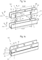
- Fig. 1 (a) shows an assembly 10 of a first busbar 1 and a second busbar 1 'of a first embodiment of the invention in an unassembled state U.
- the busbars 1, 1' are formed in cross-section U-shaped. They extend in a longitudinal direction 31 and surround an inner space 100, which is usable for the electrically contacting arrangement of electrical conductors (not shown).
- Both busbars 1, 1 ' have two surfaces 12, 13, 12', 13 ', here also called leg surfaces, each extending in the longitudinal direction 31 and a joining direction 32.
- the leg surfaces 12, 13, 12 ', 13' of the busbars 1, 1 ' are connected to each other by a connecting surface 11, 11', which extends in the longitudinal direction 31 and a transverse direction 33.
- the busbars 1, 1 ' are integrally formed as a punching bending component of a metal sheet.
- the leg surfaces 12, 12 ', 13, 13' by bending the sheet by about a right angle (not shown) relative to the connecting surface 11, 11 'is formed. Therefore, the leg surfaces 12, 13, 12 ', 13' in each case at a bending edge 171, 172, 171 ', 172', which extends in the longitudinal direction 31, with the connecting surface 11, 11 'are connected.
- two recesses are respectively arranged, which are provided as a contact receptacles 14 and serve to receive contact tabs 15 'of the second busbar 1'.
- a contour of the contact tabs 15 'of the second busbar 1' is corresponding to a contour formed the contact receptacles 14 of the first busbar 1, so that the contact tabs 15 'respectively in the contact receptacles 14 fit.
- the contact receptacles 14 each extend from the bending edge 171, 172 into the leg surface 12, 13 of the first busbar 1.
- the contact receptacles 14 of the opposite leg surfaces 12, 13 each have the same distance A1, A2 to each other.
- the contact receptacles 14 of the one of the two leg surfaces 12, 13 in the longitudinal direction 31 relative to the contact receptacles 14 of the other of the two surfaces 12, 13 offset by an offset .DELTA.A each other.
- two contact tabs 15' are arranged in an analogous manner. Also, the contact tabs 15 'have on the leg surfaces 12', 13 'in each case the same distance A1', A2 'to each other. However, the contact tabs 15 'of the one of the two leg surfaces 12', 13 'in the longitudinal direction 31 relative to the contact tabs 15' of the other of the two surfaces 12 ', 13' offset by an offset .DELTA.A 'to each other.
- the offset .DELTA.A, .DELTA.A ' is the same here for both busbars 1, 1'.
- the busbars 1, 1 ' can be arranged one above the other. In addition, they are nestable with each other, so that they are arranged at an angle to each other.
- further busbars (not shown) with these two busbars 1, 1 'can be connected. In each case, only the contact tabs 15 'one of the two leg surfaces 12', 13 'of the second busbar 1' with the contact receptacles 14 one of the two leg surfaces 13, 12 of the first busbar 1 connected to each other.
- a length L of the two busbars 1, 1 'and a width B of the two busbars 1, 1' are the same here.
- different widths and / or different lengths busbars 1, 1 ' are connected to each other, as long as the distance A1, A2, A1', A2 'of the contact tabs 15' and the contact receptacles 14 are formed to match each other, and the contours of the contact tabs 15th 'and the contact receptacles 14 correspond to each other.
- both the contact tabs 15' and the contact receptacles 14 each have a contact head 152 ', 142 and a contact neck 151', 141.
- the contact neck 151 ', 141 is formed narrower relative to the contact head 152', 142.
- the contact tab 15 'overall has a smaller contour than the contact receptacle 14, so that it can be inserted or latched into the contact receptacle 14.
- Fig. 1 (b) shows the arrangement 10 of Fig. 1 (a) during assembly.
- the contact tabs 15 'of the second busbar 1' are engaged in the contact receptacles 14 of the first busbar 1.
- a first of the two contact tabs 15 'one of the two leg surfaces 13' of the second busbar 1 'in the contact receptacle 14 of the first busbar 1 is shown.
- the contact lug 15 ' is not yet embossed with the contact receptacle 14, so that the busbars 1, 1' at this contact tab 15 'and contact receptacle 14 are not yet mechanically positively connected and not yet defined electrically contacting each other.
- the first of the two contact tabs 15 'and their contact receptacle 14 are shown during embossing with an embossing tool 2.
- a counter-tool (not shown) is arranged in the interior 100 (not visible here) that holds the contact tab 15 'in the contact receptacle 14.
- the embossing tool 2 is then pressed onto the contact tab 15 'with pressure, for example with a hammer (not shown).
- it is positively and preferably also non-positively connected and good electrically conductive with the contact receptacle 14.
- the third section (III) shows the second of the two contact lugs 15 'of the leg surface 13' of the second busbar 1 'in the contact receptacle 14 of the first busbar 1 enlarged.
- This contact plate 15 'and Druckability14 are already embossed with each other.
- the third section (III) therefore shows the connection state V.
- Fig. 1 (c) shows the two busbars 1, 1 'in the connection state V. All contact lugs 15' of the second busbar 1 'are each embossed with their contact receptacles 14 of the first busbar 1.
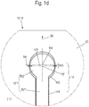
- Fig. 1 (d) shows the first part of the Fig. 1 (b) enlarged again.
- the contact tab 15 ' has a substantially round contact head 152'.
- the contact head 142 of the contact receptacle 14 here approximately centrally in the joining direction 30, an extension 143, so that the contact head 142 is formed here approximately elliptical.
- the contact tab 15 ' is at least slightly displaceable in the contact receptacle 14 in or against the joining direction 30.
- an at least slight play in or against the joining direction 30 can be compensated.
- a width b5 'of the contact head 152' of the contact tab 15 'in its center M5' is only slightly smaller than a width b4 of the contact head 142 of the contact receptacle 14, so that when embossing in this area a mechanical positive connection, and thus an electrical connection point, can be produced in a defined manner.
- Fig. 2 shows in (a) another embodiment of an inventive arrangement 10 in the connection state V and in (b) an enlarged section of (a). It is visible that the extension 143 of the contact head 142 of the contact receptacle 14 of the first busbar 1 is significantly larger than in the Fig. 1 (d) , As a result, the contact lug 15 'of the second busbar 1' can be displaced significantly further in or against the joining direction 30. The position of the second busbar 1 'relative to the first busbar 1 is therefore significantly more adaptable in or against the joining direction 30.
- the in the Fig. 3 (a) - (c) illustrated embodiments of the arrangements 10 use flat conductor rails 1, 1 '.
- the busbars 1, 1 'therefore each have only one surface 12, 12', on or in the contact tabs 15,15 'and / or contact receptacles 14, 14' are arranged.
- Fig. 3 (a) are the two busbars 1, 1 'of the arrangement 10 of identical design.
- This is followed in each case by a contact lug 15, 15 'a contact receptacle 14, 14'.
- the contact tabs 15, 15 'at one edge 161, 161' relative to those at the other edge 162, 162 'offset.
- the offset (not designated) is selected so that a contact lug 15, 15 'at one edge 161, 161' is in each case a contact receptacle 14, 14 'at the other edge 162, 162' opposite.
- two contact lugs 15 are arranged at the opposite edges 161, 162 of the first busbar 1, while at the opposite edges 161 ', 162' of the second busbar 1 'each two contact receptacles 14' are arranged.
- the contact tabs 15 or contact receptacles 14 'arranged on the opposite edges 161, 162, 161', 162 'of the same busbar 1, 1' are offset from each other.
- a shielding potential surface can be formed.
- the arrangement can also be used for electrically conductive connection with electrical conductors.
- busbars 1, 1 'of Fig. 3 (a) and (B) have the busbars 1, 1 'of the arrangement 10 of Fig. 3 (c) in each case only one contact tab 15, 15 'at one edge 161, 161', and a contact receptacle 14, 14 'at the other edge 162, 162' on.
- the contact head 152, 152 ', 142, 142' of the contact tab 15, 15 'and the contact receptacle 14, 14' is not round or elliptical, but rectangular.
- the contact tab 15, 15 'of a busbar 1, 1' after insertion into the contact receptacle 14, 14 'of the other busbar 1, 1' by embossing, in particular the contact heads 152, 152 ', 142, 142', mechanically positively connected and preferably also non-positively and electrically contacting with each other connectable.
- Fig. 4 (a) shows a further embodiment of an inventive arrangement in an assembled state.
- contact tab and contact are formed approximately L-shaped.
- the contact neck of the contact is wider by a distance ⁇ 31 than the contact neck of the contact lug.
- the contact head of the contact is about the same distance ⁇ 31 longer than the contact head of the contact tab.
- the second busbar is displaceable relative to the first busbar by the distance, here in or against the longitudinal direction. As a result, a game in or against the longitudinal direction can be compensated.
- FIG. 4 (b) an arrangement with a first and a second busbar 1, 1 'in the assembled state M, in which the contact tab 15' and the contact receptacle 14 no contact head 152 ', 142 have. But the contact tab 15 'and the contact receptacle 14 taper towards the edge 161, 162' of their busbar 1, 1 'out. After inserting the contact tab 15 'in the contact receptacle 14, the contact tab 15' is held captive in the contact receptacle 14 even without embossing even in this embodiment.
Landscapes
- Engineering & Computer Science (AREA)
- Mechanical Engineering (AREA)
- Coupling Device And Connection With Printed Circuit (AREA)
- Connections Effected By Soldering, Adhesion, Or Permanent Deformation (AREA)
Applications Claiming Priority (1)
| Application Number | Priority Date | Filing Date | Title |
|---|---|---|---|
| DE102018108535.4A DE102018108535A1 (de) | 2018-04-11 | 2018-04-11 | Stromschiene, Anordnung aus zumindest zwei Stromschienen sowie Verfahren zum Verbinden der Stromschienen |
Publications (2)
| Publication Number | Publication Date |
|---|---|
| EP3553891A1 true EP3553891A1 (fr) | 2019-10-16 |
| EP3553891B1 EP3553891B1 (fr) | 2023-04-26 |
Family
ID=66101921
Family Applications (1)
| Application Number | Title | Priority Date | Filing Date |
|---|---|---|---|
| EP19167534.7A Active EP3553891B1 (fr) | 2018-04-11 | 2019-04-05 | Ensemble constitué d'au moins deux rails d'alimentation et procédé d'assemblage dudit ensemble |
Country Status (3)
| Country | Link |
|---|---|
| EP (1) | EP3553891B1 (fr) |
| DE (1) | DE102018108535A1 (fr) |
| PL (1) | PL3553891T3 (fr) |
Cited By (3)
| Publication number | Priority date | Publication date | Assignee | Title |
|---|---|---|---|---|
| WO2024127874A1 (fr) * | 2022-12-12 | 2024-06-20 | 矢崎総業株式会社 | Structure de connexion de barres omnibus |
| DE102023102473A1 (de) | 2023-02-01 | 2024-08-01 | Man Truck & Bus Se | Elektrisches Verbindungssystem aufweisend eine erste Stromschiene, eine zweite Stromschiene und eine Ummantelung |
| EP4576438A1 (fr) * | 2023-12-18 | 2025-06-25 | Robert Bosch GmbH | Dispositif d'interface pour la connexion électrique entre un moteur électrique et un onduleur, par exemple dans un axe électrique, procédé de fabrication du dispositif d'interface et axe électrique |
Families Citing this family (1)
| Publication number | Priority date | Publication date | Assignee | Title |
|---|---|---|---|---|
| DE102022130265A1 (de) | 2022-11-16 | 2024-05-16 | Dr. Ing. H.C. F. Porsche Aktiengesellschaft | Elektronikeinheit für einen Einsatz im Kraftfahrzeugbereich sowie Wechselrichteranordnung |
Citations (3)
| Publication number | Priority date | Publication date | Assignee | Title |
|---|---|---|---|---|
| DE69906233T2 (de) * | 1998-12-14 | 2003-11-06 | Schneider Electric Industries Sas, Rueil-Malmaison | Elektrische Verbindung für Sammelschiene |
| DE102009018945A1 (de) * | 2009-04-27 | 2010-10-28 | Siemens Aktiengesellschaft | Modular verlängerbares Stromschienenstück in Flachprofilausführung zur überlappend ineinandergreifenden Fügung mit einem weiteren Stromschienstück in Richtung der Profilstärke |
| DE102012212907A1 (de) * | 2012-07-24 | 2014-01-30 | Siemens Aktiengesellschaft | Vorrichtung zur Verbindung zweier flach ausgebildeter Werkstücke und Verfahren zum Verbinden |
Family Cites Families (2)
| Publication number | Priority date | Publication date | Assignee | Title |
|---|---|---|---|---|
| WO2014067849A1 (fr) | 2012-10-30 | 2014-05-08 | Weidmüller Interface GmbH & Co. KG | Ensemble de modules en série pourvu d'un système de bus d'énergie |
| DE202013103444U1 (de) | 2013-07-31 | 2014-11-04 | Weidmüller Interface GmbH & Co. KG | Kontaktelement für eine Steckanordnung eines insbesondere außen geführten Bussystems |
-
2018
- 2018-04-11 DE DE102018108535.4A patent/DE102018108535A1/de active Pending
-
2019
- 2019-04-05 PL PL19167534.7T patent/PL3553891T3/pl unknown
- 2019-04-05 EP EP19167534.7A patent/EP3553891B1/fr active Active
Patent Citations (3)
| Publication number | Priority date | Publication date | Assignee | Title |
|---|---|---|---|---|
| DE69906233T2 (de) * | 1998-12-14 | 2003-11-06 | Schneider Electric Industries Sas, Rueil-Malmaison | Elektrische Verbindung für Sammelschiene |
| DE102009018945A1 (de) * | 2009-04-27 | 2010-10-28 | Siemens Aktiengesellschaft | Modular verlängerbares Stromschienenstück in Flachprofilausführung zur überlappend ineinandergreifenden Fügung mit einem weiteren Stromschienstück in Richtung der Profilstärke |
| DE102012212907A1 (de) * | 2012-07-24 | 2014-01-30 | Siemens Aktiengesellschaft | Vorrichtung zur Verbindung zweier flach ausgebildeter Werkstücke und Verfahren zum Verbinden |
Cited By (5)
| Publication number | Priority date | Publication date | Assignee | Title |
|---|---|---|---|---|
| WO2024127874A1 (fr) * | 2022-12-12 | 2024-06-20 | 矢崎総業株式会社 | Structure de connexion de barres omnibus |
| JP2024083851A (ja) * | 2022-12-12 | 2024-06-24 | 矢崎総業株式会社 | バスバー連結構造 |
| JP7541069B2 (ja) | 2022-12-12 | 2024-08-27 | 矢崎総業株式会社 | バスバー連結構造 |
| DE102023102473A1 (de) | 2023-02-01 | 2024-08-01 | Man Truck & Bus Se | Elektrisches Verbindungssystem aufweisend eine erste Stromschiene, eine zweite Stromschiene und eine Ummantelung |
| EP4576438A1 (fr) * | 2023-12-18 | 2025-06-25 | Robert Bosch GmbH | Dispositif d'interface pour la connexion électrique entre un moteur électrique et un onduleur, par exemple dans un axe électrique, procédé de fabrication du dispositif d'interface et axe électrique |
Also Published As
| Publication number | Publication date |
|---|---|
| EP3553891B1 (fr) | 2023-04-26 |
| DE102018108535A1 (de) | 2019-10-17 |
| PL3553891T3 (pl) | 2023-08-28 |
Similar Documents
| Publication | Publication Date | Title |
|---|---|---|
| EP3080875B2 (fr) | Cadre de retenue pour un connecteur par enfichage | |
| DE102013113975B4 (de) | Halterahmen für einen Steckverbinder | |
| EP3080874B1 (fr) | Cadre de retenue pour un connecteur par enfichage | |
| EP3553891B1 (fr) | Ensemble constitué d'au moins deux rails d'alimentation et procédé d'assemblage dudit ensemble | |
| DE69328662T2 (de) | Filterverbinder hoher Dichte | |
| DE10351289A1 (de) | Steckbrücke für elektrische Anschluß und/oder Verbindungsklemmen und elektrische Anschluß- und/oder Verbindungsklemme | |
| DE102016116968A1 (de) | Stromschienenverbinder | |
| DE202015106730U1 (de) | Stecker für Durchgangsverdrahtung | |
| DE102009030645B4 (de) | Brückerelement und Set aus zumindest einem Klemmelement und Brückerelement | |
| EP2393160B1 (fr) | Bornier de répartition de forme étagée | |
| DE102015119850A1 (de) | Kontaktelement mit einer an einem Kontaktkörper angeordneten Kontaktlamelle | |
| DE102015102257A1 (de) | Elektrische Reihenklemme | |
| DE4431274C2 (de) | Verfahren zum Herstellen eines Elektro-Installationsgerätes sowie Elektro-Installationsgerät | |
| DE102013114272A1 (de) | Reihenklemme | |
| DE2802686A1 (de) | Federklemme mit mehrfach-steckanschluss zum anschluss oder zur verbindung elektrischer leiter | |
| EP2568552B1 (fr) | Dispositif de support de câble | |
| EP1082784B1 (fr) | Connecteur a fiches h.f. a tranchants decales | |
| DE202011002740U1 (de) | Stromschienenanschluss, insbesondere für eine Reihenklemme | |
| EP0745260A1 (fr) | Contact de rupture avec des pieces de contact en pont mobiles les unes par rapport aux autres | |
| DE102011001152A1 (de) | Kontaktelement und Kontaktelementbaueinheit | |
| EP2173011B1 (fr) | Dispositif de liaison électrique de terminaux de cellules | |
| EP3183779A1 (fr) | Élément de contact et connecteur | |
| DE102019134579A1 (de) | Steckverbindung, Steckmodul und Kontaktelement | |
| DE102024114160A1 (de) | Flachkontaktbuchse mit federndem Kontaktelement | |
| DE102021108317A1 (de) | Klemme zum Anschluss eines elektrischen Leiters |
Legal Events
| Date | Code | Title | Description |
|---|---|---|---|
| PUAI | Public reference made under article 153(3) epc to a published international application that has entered the european phase |
Free format text: ORIGINAL CODE: 0009012 |
|
| STAA | Information on the status of an ep patent application or granted ep patent |
Free format text: STATUS: THE APPLICATION HAS BEEN PUBLISHED |
|
| AK | Designated contracting states |
Kind code of ref document: A1 Designated state(s): AL AT BE BG CH CY CZ DE DK EE ES FI FR GB GR HR HU IE IS IT LI LT LU LV MC MK MT NL NO PL PT RO RS SE SI SK SM TR |
|
| AX | Request for extension of the european patent |
Extension state: BA ME |
|
| STAA | Information on the status of an ep patent application or granted ep patent |
Free format text: STATUS: REQUEST FOR EXAMINATION WAS MADE |
|
| RAP1 | Party data changed (applicant data changed or rights of an application transferred) |
Owner name: WEIDMUELLER INTERFACE GMBH & CO. KG |
|
| 17P | Request for examination filed |
Effective date: 20200406 |
|
| RBV | Designated contracting states (corrected) |
Designated state(s): AL AT BE BG CH CY CZ DE DK EE ES FI FR GB GR HR HU IE IS IT LI LT LU LV MC MK MT NL NO PL PT RO RS SE SI SK SM TR |
|
| RIN1 | Information on inventor provided before grant (corrected) |
Inventor name: STJEPANOVIC, KARLO Inventor name: RUTZ, ANDREAS Inventor name: FEHLING, STEPHAN Inventor name: KRUPINSKI, RUDOLF Inventor name: HENZE, ROMAN Inventor name: HACKEMACK, FRANK Inventor name: FISCHER, STEFAN |
|
| STAA | Information on the status of an ep patent application or granted ep patent |
Free format text: STATUS: EXAMINATION IS IN PROGRESS |
|
| 17Q | First examination report despatched |
Effective date: 20210323 |
|
| RIC1 | Information provided on ipc code assigned before grant |
Ipc: H01R 4/06 20060101ALN20221012BHEP Ipc: H02G 5/00 20060101ALI20221012BHEP Ipc: H01R 11/01 20060101ALI20221012BHEP Ipc: B29C 65/56 20060101ALI20221012BHEP Ipc: B21D 39/03 20060101ALI20221012BHEP Ipc: H01R 4/26 20060101AFI20221012BHEP |
|
| GRAP | Despatch of communication of intention to grant a patent |
Free format text: ORIGINAL CODE: EPIDOSNIGR1 |
|
| STAA | Information on the status of an ep patent application or granted ep patent |
Free format text: STATUS: GRANT OF PATENT IS INTENDED |
|
| RIC1 | Information provided on ipc code assigned before grant |
Ipc: H01R 4/06 20060101ALN20221019BHEP Ipc: H02G 5/00 20060101ALI20221019BHEP Ipc: H01R 11/01 20060101ALI20221019BHEP Ipc: B29C 65/56 20060101ALI20221019BHEP Ipc: B21D 39/03 20060101ALI20221019BHEP Ipc: H01R 4/26 20060101AFI20221019BHEP |
|
| RIC1 | Information provided on ipc code assigned before grant |
Ipc: H01R 4/06 20060101ALN20221026BHEP Ipc: H02G 5/00 20060101ALI20221026BHEP Ipc: H01R 11/01 20060101ALI20221026BHEP Ipc: B29C 65/56 20060101ALI20221026BHEP Ipc: B21D 39/03 20060101ALI20221026BHEP Ipc: H01R 4/26 20060101AFI20221026BHEP |
|
| RIC1 | Information provided on ipc code assigned before grant |
Ipc: H01R 4/06 20060101ALN20221102BHEP Ipc: H02G 5/00 20060101ALI20221102BHEP Ipc: H01R 11/01 20060101ALI20221102BHEP Ipc: B29C 65/56 20060101ALI20221102BHEP Ipc: B21D 39/03 20060101ALI20221102BHEP Ipc: H01R 4/26 20060101AFI20221102BHEP |
|
| INTG | Intention to grant announced |
Effective date: 20221118 |
|
| GRAS | Grant fee paid |
Free format text: ORIGINAL CODE: EPIDOSNIGR3 |
|
| GRAA | (expected) grant |
Free format text: ORIGINAL CODE: 0009210 |
|
| STAA | Information on the status of an ep patent application or granted ep patent |
Free format text: STATUS: THE PATENT HAS BEEN GRANTED |
|
| AK | Designated contracting states |
Kind code of ref document: B1 Designated state(s): AL AT BE BG CH CY CZ DE DK EE ES FI FR GB GR HR HU IE IS IT LI LT LU LV MC MK MT NL NO PL PT RO RS SE SI SK SM TR |
|
| REG | Reference to a national code |
Ref country code: GB Ref legal event code: FG4D Free format text: NOT ENGLISH |
|
| REG | Reference to a national code |
Ref country code: CH Ref legal event code: EP |
|
| REG | Reference to a national code |
Ref country code: DE Ref legal event code: R096 Ref document number: 502019007536 Country of ref document: DE |
|
| REG | Reference to a national code |
Ref country code: AT Ref legal event code: REF Ref document number: 1563511 Country of ref document: AT Kind code of ref document: T Effective date: 20230515 |
|
| REG | Reference to a national code |
Ref country code: IE Ref legal event code: FG4D Free format text: LANGUAGE OF EP DOCUMENT: GERMAN |
|
| P01 | Opt-out of the competence of the unified patent court (upc) registered |
Effective date: 20230704 |
|
| REG | Reference to a national code |
Ref country code: LT Ref legal event code: MG9D |
|
| REG | Reference to a national code |
Ref country code: NL Ref legal event code: MP Effective date: 20230426 |
|
| PG25 | Lapsed in a contracting state [announced via postgrant information from national office to epo] |
Ref country code: NL Free format text: LAPSE BECAUSE OF FAILURE TO SUBMIT A TRANSLATION OF THE DESCRIPTION OR TO PAY THE FEE WITHIN THE PRESCRIBED TIME-LIMIT Effective date: 20230426 |
|
| PG25 | Lapsed in a contracting state [announced via postgrant information from national office to epo] |
Ref country code: SE Free format text: LAPSE BECAUSE OF FAILURE TO SUBMIT A TRANSLATION OF THE DESCRIPTION OR TO PAY THE FEE WITHIN THE PRESCRIBED TIME-LIMIT Effective date: 20230426 Ref country code: PT Free format text: LAPSE BECAUSE OF FAILURE TO SUBMIT A TRANSLATION OF THE DESCRIPTION OR TO PAY THE FEE WITHIN THE PRESCRIBED TIME-LIMIT Effective date: 20230828 Ref country code: NO Free format text: LAPSE BECAUSE OF FAILURE TO SUBMIT A TRANSLATION OF THE DESCRIPTION OR TO PAY THE FEE WITHIN THE PRESCRIBED TIME-LIMIT Effective date: 20230726 Ref country code: ES Free format text: LAPSE BECAUSE OF FAILURE TO SUBMIT A TRANSLATION OF THE DESCRIPTION OR TO PAY THE FEE WITHIN THE PRESCRIBED TIME-LIMIT Effective date: 20230426 |
|
| PG25 | Lapsed in a contracting state [announced via postgrant information from national office to epo] |
Ref country code: RS Free format text: LAPSE BECAUSE OF FAILURE TO SUBMIT A TRANSLATION OF THE DESCRIPTION OR TO PAY THE FEE WITHIN THE PRESCRIBED TIME-LIMIT Effective date: 20230426 Ref country code: LV Free format text: LAPSE BECAUSE OF FAILURE TO SUBMIT A TRANSLATION OF THE DESCRIPTION OR TO PAY THE FEE WITHIN THE PRESCRIBED TIME-LIMIT Effective date: 20230426 Ref country code: LT Free format text: LAPSE BECAUSE OF FAILURE TO SUBMIT A TRANSLATION OF THE DESCRIPTION OR TO PAY THE FEE WITHIN THE PRESCRIBED TIME-LIMIT Effective date: 20230426 Ref country code: IS Free format text: LAPSE BECAUSE OF FAILURE TO SUBMIT A TRANSLATION OF THE DESCRIPTION OR TO PAY THE FEE WITHIN THE PRESCRIBED TIME-LIMIT Effective date: 20230826 Ref country code: HR Free format text: LAPSE BECAUSE OF FAILURE TO SUBMIT A TRANSLATION OF THE DESCRIPTION OR TO PAY THE FEE WITHIN THE PRESCRIBED TIME-LIMIT Effective date: 20230426 Ref country code: GR Free format text: LAPSE BECAUSE OF FAILURE TO SUBMIT A TRANSLATION OF THE DESCRIPTION OR TO PAY THE FEE WITHIN THE PRESCRIBED TIME-LIMIT Effective date: 20230727 |
|
| PG25 | Lapsed in a contracting state [announced via postgrant information from national office to epo] |
Ref country code: FI Free format text: LAPSE BECAUSE OF FAILURE TO SUBMIT A TRANSLATION OF THE DESCRIPTION OR TO PAY THE FEE WITHIN THE PRESCRIBED TIME-LIMIT Effective date: 20230426 |
|
| PG25 | Lapsed in a contracting state [announced via postgrant information from national office to epo] |
Ref country code: SK Free format text: LAPSE BECAUSE OF FAILURE TO SUBMIT A TRANSLATION OF THE DESCRIPTION OR TO PAY THE FEE WITHIN THE PRESCRIBED TIME-LIMIT Effective date: 20230426 |
|
| REG | Reference to a national code |
Ref country code: DE Ref legal event code: R097 Ref document number: 502019007536 Country of ref document: DE |
|
| PG25 | Lapsed in a contracting state [announced via postgrant information from national office to epo] |
Ref country code: SM Free format text: LAPSE BECAUSE OF FAILURE TO SUBMIT A TRANSLATION OF THE DESCRIPTION OR TO PAY THE FEE WITHIN THE PRESCRIBED TIME-LIMIT Effective date: 20230426 Ref country code: SK Free format text: LAPSE BECAUSE OF FAILURE TO SUBMIT A TRANSLATION OF THE DESCRIPTION OR TO PAY THE FEE WITHIN THE PRESCRIBED TIME-LIMIT Effective date: 20230426 Ref country code: RO Free format text: LAPSE BECAUSE OF FAILURE TO SUBMIT A TRANSLATION OF THE DESCRIPTION OR TO PAY THE FEE WITHIN THE PRESCRIBED TIME-LIMIT Effective date: 20230426 Ref country code: EE Free format text: LAPSE BECAUSE OF FAILURE TO SUBMIT A TRANSLATION OF THE DESCRIPTION OR TO PAY THE FEE WITHIN THE PRESCRIBED TIME-LIMIT Effective date: 20230426 Ref country code: DK Free format text: LAPSE BECAUSE OF FAILURE TO SUBMIT A TRANSLATION OF THE DESCRIPTION OR TO PAY THE FEE WITHIN THE PRESCRIBED TIME-LIMIT Effective date: 20230426 Ref country code: CZ Free format text: LAPSE BECAUSE OF FAILURE TO SUBMIT A TRANSLATION OF THE DESCRIPTION OR TO PAY THE FEE WITHIN THE PRESCRIBED TIME-LIMIT Effective date: 20230426 |
|
| PLBE | No opposition filed within time limit |
Free format text: ORIGINAL CODE: 0009261 |
|
| STAA | Information on the status of an ep patent application or granted ep patent |
Free format text: STATUS: NO OPPOSITION FILED WITHIN TIME LIMIT |
|
| 26N | No opposition filed |
Effective date: 20240129 |
|
| PG25 | Lapsed in a contracting state [announced via postgrant information from national office to epo] |
Ref country code: SI Free format text: LAPSE BECAUSE OF FAILURE TO SUBMIT A TRANSLATION OF THE DESCRIPTION OR TO PAY THE FEE WITHIN THE PRESCRIBED TIME-LIMIT Effective date: 20230426 |
|
| PG25 | Lapsed in a contracting state [announced via postgrant information from national office to epo] |
Ref country code: SI Free format text: LAPSE BECAUSE OF FAILURE TO SUBMIT A TRANSLATION OF THE DESCRIPTION OR TO PAY THE FEE WITHIN THE PRESCRIBED TIME-LIMIT Effective date: 20230426 |
|
| REG | Reference to a national code |
Ref country code: DE Ref legal event code: R119 Ref document number: 502019007536 Country of ref document: DE |
|
| PG25 | Lapsed in a contracting state [announced via postgrant information from national office to epo] |
Ref country code: BG Free format text: LAPSE BECAUSE OF FAILURE TO SUBMIT A TRANSLATION OF THE DESCRIPTION OR TO PAY THE FEE WITHIN THE PRESCRIBED TIME-LIMIT Effective date: 20230426 |
|
| PG25 | Lapsed in a contracting state [announced via postgrant information from national office to epo] |
Ref country code: MC Free format text: LAPSE BECAUSE OF FAILURE TO SUBMIT A TRANSLATION OF THE DESCRIPTION OR TO PAY THE FEE WITHIN THE PRESCRIBED TIME-LIMIT Effective date: 20230426 |
|
| PG25 | Lapsed in a contracting state [announced via postgrant information from national office to epo] |
Ref country code: MC Free format text: LAPSE BECAUSE OF FAILURE TO SUBMIT A TRANSLATION OF THE DESCRIPTION OR TO PAY THE FEE WITHIN THE PRESCRIBED TIME-LIMIT Effective date: 20230426 Ref country code: BG Free format text: LAPSE BECAUSE OF FAILURE TO SUBMIT A TRANSLATION OF THE DESCRIPTION OR TO PAY THE FEE WITHIN THE PRESCRIBED TIME-LIMIT Effective date: 20230426 |
|
| REG | Reference to a national code |
Ref country code: CH Ref legal event code: PL |
|
| PG25 | Lapsed in a contracting state [announced via postgrant information from national office to epo] |
Ref country code: LU Free format text: LAPSE BECAUSE OF NON-PAYMENT OF DUE FEES Effective date: 20240405 |
|
| GBPC | Gb: european patent ceased through non-payment of renewal fee |
Effective date: 20240405 |
|
| REG | Reference to a national code |
Ref country code: BE Ref legal event code: MM Effective date: 20240430 |
|
| PG25 | Lapsed in a contracting state [announced via postgrant information from national office to epo] |
Ref country code: LU Free format text: LAPSE BECAUSE OF NON-PAYMENT OF DUE FEES Effective date: 20240405 |
|
| PG25 | Lapsed in a contracting state [announced via postgrant information from national office to epo] |
Ref country code: DE Free format text: LAPSE BECAUSE OF NON-PAYMENT OF DUE FEES Effective date: 20241105 |
|
| PG25 | Lapsed in a contracting state [announced via postgrant information from national office to epo] |
Ref country code: BE Free format text: LAPSE BECAUSE OF NON-PAYMENT OF DUE FEES Effective date: 20240430 |
|
| PG25 | Lapsed in a contracting state [announced via postgrant information from national office to epo] |
Ref country code: GB Free format text: LAPSE BECAUSE OF NON-PAYMENT OF DUE FEES Effective date: 20240405 |
|
| PG25 | Lapsed in a contracting state [announced via postgrant information from national office to epo] |
Ref country code: FR Free format text: LAPSE BECAUSE OF NON-PAYMENT OF DUE FEES Effective date: 20240430 |
|
| PG25 | Lapsed in a contracting state [announced via postgrant information from national office to epo] |
Ref country code: GB Free format text: LAPSE BECAUSE OF NON-PAYMENT OF DUE FEES Effective date: 20240405 Ref country code: FR Free format text: LAPSE BECAUSE OF NON-PAYMENT OF DUE FEES Effective date: 20240430 Ref country code: DE Free format text: LAPSE BECAUSE OF NON-PAYMENT OF DUE FEES Effective date: 20241105 Ref country code: BE Free format text: LAPSE BECAUSE OF NON-PAYMENT OF DUE FEES Effective date: 20240430 Ref country code: CH Free format text: LAPSE BECAUSE OF NON-PAYMENT OF DUE FEES Effective date: 20240430 |
|
| PG25 | Lapsed in a contracting state [announced via postgrant information from national office to epo] |
Ref country code: IE Free format text: LAPSE BECAUSE OF NON-PAYMENT OF DUE FEES Effective date: 20240405 |
|
| REG | Reference to a national code |
Ref country code: AT Ref legal event code: MM01 Ref document number: 1563511 Country of ref document: AT Kind code of ref document: T Effective date: 20240405 |
|
| PGFP | Annual fee paid to national office [announced via postgrant information from national office to epo] |
Ref country code: IT Payment date: 20250424 Year of fee payment: 7 |
|
| PG25 | Lapsed in a contracting state [announced via postgrant information from national office to epo] |
Ref country code: AT Free format text: LAPSE BECAUSE OF NON-PAYMENT OF DUE FEES Effective date: 20240405 |
|
| PG25 | Lapsed in a contracting state [announced via postgrant information from national office to epo] |
Ref country code: CY Free format text: LAPSE BECAUSE OF FAILURE TO SUBMIT A TRANSLATION OF THE DESCRIPTION OR TO PAY THE FEE WITHIN THE PRESCRIBED TIME-LIMIT; INVALID AB INITIO Effective date: 20190405 |
|
| PG25 | Lapsed in a contracting state [announced via postgrant information from national office to epo] |
Ref country code: HU Free format text: LAPSE BECAUSE OF FAILURE TO SUBMIT A TRANSLATION OF THE DESCRIPTION OR TO PAY THE FEE WITHIN THE PRESCRIBED TIME-LIMIT; INVALID AB INITIO Effective date: 20190405 |
|
| PG25 | Lapsed in a contracting state [announced via postgrant information from national office to epo] |
Ref country code: PL Free format text: LAPSE BECAUSE OF NON-PAYMENT OF DUE FEES Effective date: 20240405 |
|
| PG25 | Lapsed in a contracting state [announced via postgrant information from national office to epo] |
Ref country code: TR Free format text: LAPSE BECAUSE OF FAILURE TO SUBMIT A TRANSLATION OF THE DESCRIPTION OR TO PAY THE FEE WITHIN THE PRESCRIBED TIME-LIMIT Effective date: 20230426 |