EP3554064A1 - Dispositif de détection - Google Patents
Dispositif de détection Download PDFInfo
- Publication number
- EP3554064A1 EP3554064A1 EP19167505.7A EP19167505A EP3554064A1 EP 3554064 A1 EP3554064 A1 EP 3554064A1 EP 19167505 A EP19167505 A EP 19167505A EP 3554064 A1 EP3554064 A1 EP 3554064A1
- Authority
- EP
- European Patent Office
- Prior art keywords
- sensor device
- sensors
- sensor
- beams
- arithmetic unit
- Prior art date
- Legal status (The legal status is an assumption and is not a legal conclusion. Google has not performed a legal analysis and makes no representation as to the accuracy of the status listed.)
- Withdrawn
Links
- 230000003595 spectral effect Effects 0.000 claims abstract description 28
- 238000012545 processing Methods 0.000 claims description 33
- 238000000034 method Methods 0.000 claims description 13
- 230000003287 optical effect Effects 0.000 claims description 5
- 230000000007 visual effect Effects 0.000 claims description 3
- 230000008901 benefit Effects 0.000 description 4
- 238000001514 detection method Methods 0.000 description 4
- 238000013461 design Methods 0.000 description 3
- 238000011161 development Methods 0.000 description 3
- 230000008569 process Effects 0.000 description 3
- 238000012546 transfer Methods 0.000 description 3
- 229910000831 Steel Inorganic materials 0.000 description 2
- 230000000694 effects Effects 0.000 description 2
- 238000011156 evaluation Methods 0.000 description 2
- 239000000284 extract Substances 0.000 description 2
- 238000001454 recorded image Methods 0.000 description 2
- 239000010959 steel Substances 0.000 description 2
- 241000273930 Brevoortia tyrannus Species 0.000 description 1
- 238000013459 approach Methods 0.000 description 1
- 230000005540 biological transmission Effects 0.000 description 1
- 230000008859 change Effects 0.000 description 1
- 238000010276 construction Methods 0.000 description 1
- 230000001419 dependent effect Effects 0.000 description 1
- 230000007613 environmental effect Effects 0.000 description 1
- 230000004044 response Effects 0.000 description 1
- 238000001228 spectrum Methods 0.000 description 1
- 230000006641 stabilisation Effects 0.000 description 1
- 238000011105 stabilization Methods 0.000 description 1
- 230000000087 stabilizing effect Effects 0.000 description 1
- 238000002211 ultraviolet spectrum Methods 0.000 description 1
Images
Classifications
-
- G—PHYSICS
- G02—OPTICS
- G02B—OPTICAL ELEMENTS, SYSTEMS OR APPARATUS
- G02B26/00—Optical devices or arrangements for the control of light using movable or deformable optical elements
- G02B26/08—Optical devices or arrangements for the control of light using movable or deformable optical elements for controlling the direction of light
- G02B26/10—Scanning systems
- G02B26/101—Scanning systems with both horizontal and vertical deflecting means, e.g. raster or XY scanners
-
- H—ELECTRICITY
- H04—ELECTRIC COMMUNICATION TECHNIQUE
- H04N—PICTORIAL COMMUNICATION, e.g. TELEVISION
- H04N23/00—Cameras or camera modules comprising electronic image sensors; Control thereof
- H04N23/60—Control of cameras or camera modules
- H04N23/698—Control of cameras or camera modules for achieving an enlarged field of view, e.g. panoramic image capture
-
- H—ELECTRICITY
- H04—ELECTRIC COMMUNICATION TECHNIQUE
- H04N—PICTORIAL COMMUNICATION, e.g. TELEVISION
- H04N23/00—Cameras or camera modules comprising electronic image sensors; Control thereof
- H04N23/60—Control of cameras or camera modules
- H04N23/68—Control of cameras or camera modules for stable pick-up of the scene, e.g. compensating for camera body vibrations
- H04N23/682—Vibration or motion blur correction
- H04N23/685—Vibration or motion blur correction performed by mechanical compensation
-
- H—ELECTRICITY
- H04—ELECTRIC COMMUNICATION TECHNIQUE
- H04N—PICTORIAL COMMUNICATION, e.g. TELEVISION
- H04N23/00—Cameras or camera modules comprising electronic image sensors; Control thereof
- H04N23/70—Circuitry for compensating brightness variation in the scene
- H04N23/71—Circuitry for evaluating the brightness variation
-
- H—ELECTRICITY
- H04—ELECTRIC COMMUNICATION TECHNIQUE
- H04N—PICTORIAL COMMUNICATION, e.g. TELEVISION
- H04N23/00—Cameras or camera modules comprising electronic image sensors; Control thereof
- H04N23/70—Circuitry for compensating brightness variation in the scene
- H04N23/73—Circuitry for compensating brightness variation in the scene by influencing the exposure time
Definitions
- the invention relates to a particularly optronic sensor device for detecting the surroundings of an object, in particular of a vehicle, with a rotatable viewing part which has a viewing opening through which rays of the environment can enter the viewing part. Furthermore, the invention comprises a corresponding method.
- a sensor device may be a camera system which is arranged to detect the environment on the outside of the object.
- the environment can be recorded and The recorded images can then be displayed offside or in the object, for example, on monitors and displays, without a direct view is required.
- sensor devices for observing the environment have a rotatable sighting device with a viewing opening.
- the vaulting device may be rotated about a horizontal axis of rotation so that such movement may align the gaze opening with the area of the environment to be observed. Rays reflected or emitted by the environment can then enter through the lookout opening into the lookout facility and be further processed there.
- the invention has the object to provide a sensor device of the type mentioned, which allows a reliable observation of the entire environment.
- the arrangement of several sensors in the look-ahead for detecting different spectral regions of the beams can be detected with only one sensor device multiple spectral regions. It is not necessary to detect the environment of an object with a plurality of sensor devices, which is why the described problems of mutual shading omitted. If all required spectral ranges can be detected with a sensor device, therefore, there are no more multiple sensor devices required for different angular ranges. To that end, it is advantageous if the viewing part is rotatable by 360 degrees.
- the sensor device has a beam splitter which divides the beams into a plurality of partial beams, each of the sensors being supplied with a partial beam.
- a beam splitter makes it possible to easily divide the beams, so that a partial beam can be fed to each sensor.
- the beam splitter can divide the light beams in such a way that all partial beams coincide.
- the sensors can be configured such that they can detect the incident partial beams spectrally for specific areas. For example, a sensor can detect the visible spectral range of the partial beam fed to it, another sensor can detect the NIR range of the partial beam fed to it, and a third sensor can detect the UV range of the partial beam fed to it.
- the beam splitter it is possible for the beam splitter to also divide the beams spectrally in a range-specific manner so that only beams of a certain spectral range are supplied to the different sensors.
- the sensors must then be designed only to detect the corresponding spectral range. It is also advantageous if a sensor is provided per partial beam, so that the number of sensors coincides with the number of partial beams.
- the sensor device instead of the beam splitter, has a movable mirror, via which the beams are directed onto the sensors.
- This embodiment has the advantage that the intensity of the beams is not reduced on the basis of a beam splitter, but the intensity of the beams guided onto the sensors coincides with that of the incident beam.
- the sub-beams directed to the sensors then coincide with the beams incident in the look-ahead part.
- the mirror may be movable such that the sensors are successively exposed for a certain period of time. The exposure times of the sensors can be dependent on the spectral ranges detected by the sensors. For example, it may be necessary to expose a sensor for detecting one spectral range longer than a sensor for detecting another spectral range.
- the sensor regions of the sensors can be read in sections, in particular line by line.
- the areas to be read out can be read out with a high resolution. It is advantageous if the sensor areas are narrow. For example, it is possible to read only one line of the sensor. Alternatively, it is also possible to design the sensor as a line sensor, so that it has only one line or a few readable lines.
- the detectable region of the environment is correspondingly small in the case of only a partial readout of the sensors, it is not possible in this way alone to detect a large part of the environment.
- the sensor device can thus be designed in the manner of a line scan camera.
- the image may consist of many small, juxtaposed individual images, with the width of the individual images correlating to the width of the sensor region.
- this recording method can often be used in the Edge area of images occurring bubble effect can be avoided. If only one line is read by the sensor, or if the sensor is designed as a one-line sensor, it is necessary to add a large number of individual images, which, however, leads to a high image quality.
- the lookout part can be rotated automatically and / or permanently, for example via an engine. Furthermore, it is also possible to manually move the viewing part.
- the sensor device can thus also be used in the manner of a periscope. It is also possible to capture only certain areas of the environment and not always the entire 360 degree environment.
- the width of the sensor area to be read and the rotational speed of the look-ahead part can be adapted to each other.
- the viewing part can turn faster if only a very narrow sensor area is read out or if the sensor is correspondingly narrower than a one-line sensor or as a low-line sensor.
- the environment can also be detected without rotation of the viewing part.
- the sensor areas read out it is expedient for the sensor areas read out to be correspondingly wider.
- the surroundings can also be detected within a large angular range when a wide sensor area is detected even without rotation of the viewing part.
- the sensors are designed such that they can respectively convert the sub-beams into an image signal and these are fed to a computing unit.
- an electrical, in particular digital, signal can be generated from the incident partial beams.
- This signal can be fed via a cable connection or via wireless connection of the arithmetic unit.
- the arithmetic unit may have an input interface for each sensor, which may be connected to the corresponding sensors.
- the arithmetic unit can also extract a narrow image strip from a larger image detail, in particular an image strip with a minimal distortion.
- the arithmetic unit is supplied with the instantaneous angular position of the look-ahead part in the form of an angle signal and the arithmetic unit can assign the instantaneous angle signal to the image signals.
- a corresponding angular position of the look-ahead part can be assigned to each narrow image strip in the arithmetic unit.
- the arithmetic unit can combine the eiselfn image signals and assign them to a corresponding angle signal. It is possible that all image signals are assigned the same angle signal, namely when all the image signals arrive at the same time in the arithmetic unit.
- the image signals are assigned the angle signals which correspond to the angular position of the look-ahead part at the moment of detection of the beams or of the partial beams.
- a beam falls on a sensor, which is read line by line.
- the arithmetic unit of the sensor sends the image signal and the arithmetic unit assigns the current angular position to this image signal. If the viewing part is then rotated a little bit, the rays falling on the sensor also change.
- the arithmetic unit are then forwarded again and assigned there the corresponding new angular position. This process can be very quickly with a continuous rotation of the lookout part.
- an angle sensor For detecting the angular position of the look-ahead part, an angle sensor can be provided and connected to the arithmetic unit, or the arithmetic unit can itself have an angle sensor.
- the angle sensor can be arranged in the look-ahead part or in the object.
- the arithmetic unit can be arranged together with the sensors in the look-ahead part.
- the image signals provided with the respective angular positions may be referred to as image angle signals.
- a processing unit is provided, which is coupled to the arithmetic unit and can be fed to the image angle signals output by the arithmetic unit.
- the processing unit can assemble the incoming image angle signals into a 360-degree panoramic image, in particular, this can compose the incoming data depending on the corresponding spectral range.
- the processing unit may create various views of the environment based on the fed angle signals. For example, this can create an all-round view of the IR spectral range, the NIR spectral range, the UV spectral range and / or the range of visible light.
- the processing unit can be arranged in or away from the viewing part.
- the processing unit is not arranged in the look-ahead part, since this must provide a comparatively high computing power and therefore can have a large size. Since the viewing part is rotatable and arranged, for example, on or on the object, it is advantageous if it is as light and as small as possible. Alternatively, the tasks of the processing unit, but also be taken over by the arithmetic unit.
- the processing unit is coupled to at least one operating and display unit.
- the operating and display unit can be used by the processing unit optionally generated images are retrieved and then displayed.
- the operating and display unit can for example have a display and appropriate input devices. It is possible to display different views of the environment on the corresponding display, in particular to superimpose the views of different spectral ranges.
- the operating and display unit can be of modular construction and optionally coupled to the processing unit. It is possible to connect to the processing unit also several control and display units, for example, each person can be assigned a single control and display unit. The individual operating and display units can be connected to the same processing unit.
- the processing unit can thus provide a variety of data in the manner of a server, which can then be retrieved and displayed via the operating and display units. In this way, the presentation of the environment for each person can be customized.
- the control and display units can be made relatively small and handy, since they have to provide little computing power. Furthermore, it is also possible that only certain angular ranges and not the entire environment of the vehicle is displayed on the corresponding displays of the control and display units. It is possible to select and display only certain angular ranges, for example, if enemy vehicles are to be expected or have already been sighted in these areas.
- Various operating and display units can also communicate with each other. For example, it is possible for the representations on an operating and display unit to be displayed in the same way on another operating and display unit.
- the captured images in the different spectral regions can have the same visual axis. They can therefore be displayed superimposed on each other very easily.
- the sensor device has an optical system for processing the beams and / or the partial beams.
- the optics can process the incident rays and thus increase the recording quality.
- the optics can filter, focus or widen the beams. It can serve the image erection in the sense of a reversal system.
- the optics can be designed as a lens system with one or more lenses arranged behind one another. The lenses can be movable relative to each other and thus, for example, enable a zoom function.
- the optics can be arranged in the beam path in front of the beam splitter, so that the incident beams are processed in front of the beam splitter. Alternatively, it is also possible to arrange the optics behind the beam splitter, wherein it is advantageous if each sub-beam has its own optics.
- the optics can be coupled to the arithmetic unit and controlled by it. Furthermore, the optics can also be coupled to the processing unit, so that the optics can be controlled via the operating and display devices.
- the sensor device has a deflection device for deflecting the beams.
- the deflection device can be configured such that rays from a larger elevation angle range can strike the sensors.
- the deflection device further allows that the sensors need not be arranged in the direction in the look-ahead part, in which the rays are incident in the look-ahead part. This makes possible, in that the sensors can be arranged in such a way that the sensor regions are arranged in the normal direction to the axis of rotation of the sighting device.
- this is configured as a mirror which can be oriented in elevation.
- By a particular motor movement of the mirror in elevation different light beams of the environment can be redirected to the sensors of the sensor device.
- the deflecting device can also be used to detect the direct proximity of the vehicle. This is possible in particular if the sensor device is arranged in an edge region of the object, so that then, for example, the region of the environment below the sensor device and close to the object can be detected.
- the connection between the arithmetic unit and the processing unit is designed wirelessly, the viewing part can be positioned independently and freely on or on the object.
- the deflection device is designed such that it can stabilize the visual axis. By stabilizing the viewing axis significantly sharper images can be recorded. Especially if the object moves quickly, it can easily come to blurred images. For example, if the object is designed as a vehicle and it moves at high speed on uneven terrain, sometimes the images may not reach the required quality, but blurred images may appear. Especially if the sensor areas are only read line by line and the object moves quickly, it may happen that the successive recorded line images do not match exactly, which can lead to blurring and distortion. By the deflection, these effects can be avoided.
- the deflection device can be designed as a movable mirror with which movements of the object can be compensated.
- the mirror can be pivoted about one, two or even three axes and stabilize the line of sight in the manner of a gimbal.
- the deflection device can be coupled to the arithmetic unit and aligned by it, so that there is a stabilization.
- the arithmetic unit can, for example, evaluate the image signals of the sensors and control the deflection device in order to stabilize the line of sight or the corresponding images.
- the viewing part is rotatably mounted relative to a carrier.
- the carrier may include the processing unit as well as the display and control units. Furthermore, it is possible for the carrier to be arranged inside the object and for the viewing part to be arranged outside the object. There may be a wired or wireless connection between the lookout and the carrier. It has proven particularly advantageous if a sliding contact is provided for data transmission between the viewing part and the carrier. For example, data can be transmitted between the arithmetic unit and the processing unit via the sliding contact.
- the sliding contact can be configured as a slip ring or as a rotary ring and the viewing part can be arranged concentrically on the sliding contact.
- the sliding contact can be configured as an electrical sliding contact or as an optical rotary transformer.
- the view opening is made lockable.
- an incidence of light into the viewing opening and damage to the sensors can be prevented if, for example, high-energy laser light is incident through the viewing opening into the viewing part.
- back reflections can be prevented, which is a location of the viewing device or the Object can facilitate.
- the view opening can be closed via a panel.
- the viewing opening may have a window which can be darkened.
- the disk can be made spectrally selective.
- At least one brightness sensor is provided for detecting the brightness of the surroundings.
- the brightness sensors can be connected to the arithmetic unit and the arithmetic unit can determine the exposure times for the in particular optronic sensors from the sensor data of the brightness sensors.
- the control and transfer electronics can be used instead of the arithmetic unit.
- the arithmetic unit can be configured such that it can determine specific image information from the image signals and adjusts the exposure time of the sensors as a function of the brightness information. For example, brightness information from the image signals or from the recorded images can be evaluated and then the exposure times for the following images can be adapted. For example, the arithmetic unit may check the images at regular intervals for their brightness and / or recording quality and then adjust the exposure time accordingly. The check can be carried out, for example, based on an evaluation of a histogram of the images. Alternatively, the control and transfer electronics can be used instead of the arithmetic unit. With this method, it is also possible to vary the exposure of the sensors by selection and / or line by line, whereby the image quality can be further improved.
- the method can be developed analogously to the features of the sensor device described above. This results in the advantages described with regard to the corresponding features.
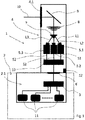
- Fig. 1 shows a schematic side view of a particular optronic sensor device.
- a sensor device 1 can be provided as a viewing device. This sensor device 1 can record the environment in the manner of a camera and the corresponding images can then be directed into the interior of the vehicle 2 and displayed there on display devices. Such sensor devices 1 are often used in the military field, since corresponding vehicles 2 are usually heavily armored and have no or only very small windows, through which a sufficient detection of the environment is not possible.
- an ambient observation based on the IR range, NIR range and / or UV range can also provide important information, for example during night driving or when objects are camouflaged or hidden.
- the sensor device 1 has a viewing part 4 with a viewing opening 4.1, through which rays L0, in particular light rays in the visible range, in the IR range, NIR range and / or UV range, can invade the surroundings into the viewing part 4.
- the look-ahead part 4 is rotatable by n x 360 degrees.
- the view opening 4.1 has an aperture, not shown in the illustration, with which the view opening 4.1 can optionally be closed.
- the rays L0 initially fall onto a deflection device designed as a mirror 9 and are then guided to an optical system 8.
- the optics 8 consists of several relatively movable lenses and thus allows a zoom function.
- a beam splitter 7 is arranged after the optics 8, which can divide the incident beams L0 into a plurality of partial beams L1, L2, L3.
- the steel L0 is divided into three, in particular, identical partial beams L1, L2, L3, which are then respectively fed to a sensor 5.1, 5.2, 5.3.
- the sensors 5.1, 5.2, 5.3 are designed such that they can each detect one spectral range.
- the Sensor 5.1 is set up to detect the NIR spectrum of the partial beam L1
- the sensor 5.2 is set up to detect the UV spectrum of the partial beam L2
- the sensor 5.3 is set up to detect the spectral range of the partial beam L3 visible to a human
- the sensors 5.1, 5.2, 5.3 convert the detected beams L1, L2, L3 respectively into corresponding image signals S1, S2, S3, which are then fed to a computer unit 10.
- the arithmetic unit 10 is coupled to an angle sensor 12 which detects the angular position of the look-ahead part 4.
- the arithmetic unit 10 assigns the image signals S1, S2, S3 the instantaneous angular position of the look-ahead part 4 and then forwards the data via a slip ring 6 to a processing unit 3.
- the function of the rotation of the look-ahead part 4 and the detection of the angular position and the more accurate design of the sensors 5.1, 5.2, 5.3 will be explained in more detail below.
- the particular optronic sensors 5.1, 5.2 and 5.3 have a predetermined sensor area, incident on the light rays and then by the sensors 5.1, 5.2, 5.3 can be detected.
- the sensors 5.1, 5.2, 5.3 detect only a very narrow sensor area, for example a line.
- the image signals S1, S2, S3 output by the sensors then correspond only to a very narrow image detail, for example only one row of pixels.
- the environment can be detected line by line. For this reason, however, it is necessary to assign the narrow image sections the angular position of the look-ahead part 4 at the moment of the recording. Based on the angle information, the individual image sections can then be placed next to one another to produce a 360-degree panoramic image of the environment.
- the evaluation and further processing of the individual images therefore does not take place in the computing unit 10 arranged in the look-ahead part 4, which functions as control and transfer electronics, but in the processing unit 3 downstream of the computing unit 10.
- This is arranged in a carrier 2.1 which is located in the vehicle 2 itself is arranged and therefore not rotated together with the view part 4.
- an electric or optical rotary transformer in particular a slip ring 6, is arranged between the viewing part 4 and the carrier 2.1 or the vehicle 2.
- the image angle signals generated by the arithmetic unit 10, which include the image signals S1, S2, S3 and the corresponding angle signals, are forwarded to the processing unit 3 via the slip ring 6.
- the individual image sections are then combined to form a 360-degree panorama image. Because of the three sensors 5.1, 5.2, 5.3, three 360-degree panoramic images are also generated in parallel in the processing unit 3.
- the processing unit 3 can superimpose and digitally process the various images of the different spectral ranges, for which purpose it is designed with a video processor unit.
- the processing unit 3 To represent the processed by the processing unit 3 image data this is connected to a plurality of control and display devices 11.
- the operating and display devices 11 can be used to give instructions to the processing unit 3 to superimpose the images, to provide them with artificial objects, to enlarge them, to downsize them or to work them up in some other way.
- the processed images are then provided to the operating and display devices 11.
- the images provided by the processing unit 3 can be retrieved and displayed. It can also be controlled via the control and display devices 11, which should be displayed for an environmental view.
- the various operating and display devices 11 there is the possibility of selecting different and individually prepared images of the environment.
- sensor device 1 can be used.
- the procedure of detecting the environment differs from the procedure described above in that the sensors 5.1, 5.2, 5.3 capture not only a very narrow sensor area, but a wider area.
- the arithmetic unit 10 downstream of the sensors 5.1, 5.2, 5.3 then extracts narrow image areas from the corresponding images with the least possible distortion. These can then be assembled by the processing unit 3 in the manner described above and made available to the operating and display devices 11.
- the sensors 5.1, 5.3, 5.3 capture broad areas, then corresponding images of the environment can be recorded. In this case, it is not necessary to constantly rotate the look-ahead part 4, but this one can then be directed in the manner of a periscope on the observed areas of the environment and the corresponding images are displayed on the control and display devices 11.
Landscapes
- Physics & Mathematics (AREA)
- General Physics & Mathematics (AREA)
- Optics & Photonics (AREA)
- Engineering & Computer Science (AREA)
- Multimedia (AREA)
- Signal Processing (AREA)
- Closed-Circuit Television Systems (AREA)
- Studio Devices (AREA)
Applications Claiming Priority (1)
| Application Number | Priority Date | Filing Date | Title |
|---|---|---|---|
| DE102018108477.3A DE102018108477A1 (de) | 2018-04-10 | 2018-04-10 | Sensorvorrichtung |
Publications (1)
| Publication Number | Publication Date |
|---|---|
| EP3554064A1 true EP3554064A1 (fr) | 2019-10-16 |
Family
ID=66323655
Family Applications (1)
| Application Number | Title | Priority Date | Filing Date |
|---|---|---|---|
| EP19167505.7A Withdrawn EP3554064A1 (fr) | 2018-04-10 | 2019-04-05 | Dispositif de détection |
Country Status (2)
| Country | Link |
|---|---|
| EP (1) | EP3554064A1 (fr) |
| DE (1) | DE102018108477A1 (fr) |
Citations (3)
| Publication number | Priority date | Publication date | Assignee | Title |
|---|---|---|---|---|
| DE3931883C1 (fr) * | 1989-09-23 | 1990-12-06 | Messerschmitt-Boelkow-Blohm Gmbh, 8012 Ottobrunn, De | |
| WO2001080550A2 (fr) * | 2000-04-13 | 2001-10-25 | Csir | Appareil photographique panoramique |
| US20110075001A1 (en) * | 2009-09-30 | 2011-03-31 | Border John N | Methods for capturing and reading out images from an image sensor |
-
2018
- 2018-04-10 DE DE102018108477.3A patent/DE102018108477A1/de active Pending
-
2019
- 2019-04-05 EP EP19167505.7A patent/EP3554064A1/fr not_active Withdrawn
Patent Citations (3)
| Publication number | Priority date | Publication date | Assignee | Title |
|---|---|---|---|---|
| DE3931883C1 (fr) * | 1989-09-23 | 1990-12-06 | Messerschmitt-Boelkow-Blohm Gmbh, 8012 Ottobrunn, De | |
| WO2001080550A2 (fr) * | 2000-04-13 | 2001-10-25 | Csir | Appareil photographique panoramique |
| US20110075001A1 (en) * | 2009-09-30 | 2011-03-31 | Border John N | Methods for capturing and reading out images from an image sensor |
Also Published As
| Publication number | Publication date |
|---|---|
| DE102018108477A1 (de) | 2019-10-10 |
Similar Documents
| Publication | Publication Date | Title |
|---|---|---|
| EP2464098B1 (fr) | Dispositif de représentation d'environnement ainsi qu'un véhicule doté d'un tel dispositif de représentation d'environnement et procédé de représentation d'une image panoramique | |
| DE3329590C2 (de) | Verfahren und Vorrichtung zur Harmonisierung mehrerer optisch/optronischer Achsen einer Zieleinrichtung auf eine gemeinsame Bezugsachse | |
| DE102010061512B4 (de) | Bilderfassungsvorrichtung, Verfahren zum Erfassen von Bildern unter Verwendung von Infrarotlicht oder sichtbarem Licht und computerlesbares Medium | |
| EP1889113B1 (fr) | Systeme avec des lunettes electroniques de vision diurne et nocturne | |
| DE2819938C2 (de) | Elektrooptisches Fernlenksystem für passive Geschosse | |
| DE102010041569B4 (de) | Digitales Kamerasystem, Farbfilterelement für digitales Kamerasystem, Verfahren zur Bestimmung von Abweichungen zwischen den Kameras eines digitalen Kamerasystems sowie Bildverarbeitungseinheit für digitales Kamerasystem | |
| EP0355310A2 (fr) | Système pour reconnaître le départ et l'approche d'objets | |
| DE3326904A1 (de) | Rundblickeinrichtung | |
| EP0342419A1 (fr) | Méthode pour l'observation d'une scène et dispositif associé | |
| DE2620699A1 (de) | Fernseh-lenksystem fuer flugkoerper | |
| DE2025934A1 (de) | Sichtgerät | |
| EP0310791A1 (fr) | Dispositif d'analyse d'une scène, en particulier pour son affichage sur l'écran d'un dispositif de visualisation | |
| DE102008058798A1 (de) | Stereokameraeinrichtungen, Verfahren zur fortlaufenden automatischen Kalibrierung einer Stereokameraeinrichtung, Computerprogramm, Computerprogrammprodukt und Überwachungsvorrichtung für Windkraftanlagen, Gebäude mit transparenten Bereichen, Start- und Landebahnen und/oder Flugkorridore von Flughäfen | |
| DE102010010030B4 (de) | Vorrichtung zum Darstellen einer Umgebung | |
| DE102005028490C5 (de) | Kamerasystem | |
| EP3554064A1 (fr) | Dispositif de détection | |
| DE4136250B4 (de) | Thermisches Abbildungssystem | |
| WO2014056473A2 (fr) | Procédé pour le traitement d'image et procédé apte à être mis en œuvre avec celui-ci pour la reconnaissance automatique d'objets et dispositif d'observation et procédé de poursuite de haute précision pour fusées au décollage à de grandes distances | |
| WO2016050334A1 (fr) | Détecteur de flamme, procédé de détection de flamme et réseau de filtres pour une puce cmos | |
| DE3941391C2 (de) | Verfahren zur passiven Detektion von Mündungsfeuer | |
| DE102013011927B4 (de) | Verfahren zum Steuern einer Überwachungseinrichtung | |
| DE102014105222A1 (de) | Kamera mit integriertem Spektrometer | |
| DE3330496A1 (de) | Einrichtung zur lenkung eines flugkoerpers in ein ziel | |
| DE102010006662B4 (de) | Vorrichtung und Verfahren zum Abbilden einer Umgebung auf eine Detektoreinrichtung | |
| DE102019130949A1 (de) | Boroskop |
Legal Events
| Date | Code | Title | Description |
|---|---|---|---|
| PUAI | Public reference made under article 153(3) epc to a published international application that has entered the european phase |
Free format text: ORIGINAL CODE: 0009012 |
|
| AK | Designated contracting states |
Kind code of ref document: A1 Designated state(s): AL AT BE BG CH CY CZ DE DK EE ES FI FR GB GR HR HU IE IS IT LI LT LU LV MC MK MT NL NO PL PT RO RS SE SI SK SM TR |
|
| AX | Request for extension of the european patent |
Extension state: BA ME |
|
| STAA | Information on the status of an ep patent application or granted ep patent |
Free format text: STATUS: THE APPLICATION IS DEEMED TO BE WITHDRAWN |
|
| 18D | Application deemed to be withdrawn |
Effective date: 20200603 |