EP3554155A1 - Ressourcenanzeigeverfahren, benutzergerät und netzwerkvorrichtung - Google Patents
Ressourcenanzeigeverfahren, benutzergerät und netzwerkvorrichtung Download PDFInfo
- Publication number
- EP3554155A1 EP3554155A1 EP17889793.0A EP17889793A EP3554155A1 EP 3554155 A1 EP3554155 A1 EP 3554155A1 EP 17889793 A EP17889793 A EP 17889793A EP 3554155 A1 EP3554155 A1 EP 3554155A1
- Authority
- EP
- European Patent Office
- Prior art keywords
- system parameter
- resource
- information
- frequency domain
- user equipment
- Prior art date
- Legal status (The legal status is an assumption and is not a legal conclusion. Google has not performed a legal analysis and makes no representation as to the accuracy of the status listed.)
- Granted
Links
Images





Classifications
-
- H—ELECTRICITY
- H04—ELECTRIC COMMUNICATION TECHNIQUE
- H04L—TRANSMISSION OF DIGITAL INFORMATION, e.g. TELEGRAPHIC COMMUNICATION
- H04L5/00—Arrangements affording multiple use of the transmission path
- H04L5/0091—Signalling for the administration of the divided path, e.g. signalling of configuration information
-
- H—ELECTRICITY
- H04—ELECTRIC COMMUNICATION TECHNIQUE
- H04L—TRANSMISSION OF DIGITAL INFORMATION, e.g. TELEGRAPHIC COMMUNICATION
- H04L5/00—Arrangements affording multiple use of the transmission path
- H04L5/003—Arrangements for allocating sub-channels of the transmission path
- H04L5/0048—Allocation of pilot signals, i.e. of signals known to the receiver
- H04L5/0051—Allocation of pilot signals, i.e. of signals known to the receiver of dedicated pilots, i.e. pilots destined for a single user or terminal
-
- H—ELECTRICITY
- H04—ELECTRIC COMMUNICATION TECHNIQUE
- H04L—TRANSMISSION OF DIGITAL INFORMATION, e.g. TELEGRAPHIC COMMUNICATION
- H04L5/00—Arrangements affording multiple use of the transmission path
- H04L5/0001—Arrangements for dividing the transmission path
- H04L5/0003—Two-dimensional division
- H04L5/0005—Time-frequency
- H04L5/0007—Time-frequency the frequencies being orthogonal, e.g. OFDM(A) or DMT
-
- H—ELECTRICITY
- H04—ELECTRIC COMMUNICATION TECHNIQUE
- H04L—TRANSMISSION OF DIGITAL INFORMATION, e.g. TELEGRAPHIC COMMUNICATION
- H04L5/00—Arrangements affording multiple use of the transmission path
- H04L5/003—Arrangements for allocating sub-channels of the transmission path
- H04L5/0053—Allocation of signalling, i.e. of overhead other than pilot signals
-
- H—ELECTRICITY
- H04—ELECTRIC COMMUNICATION TECHNIQUE
- H04W—WIRELESS COMMUNICATION NETWORKS
- H04W72/00—Local resource management
-
- H—ELECTRICITY
- H04—ELECTRIC COMMUNICATION TECHNIQUE
- H04W—WIRELESS COMMUNICATION NETWORKS
- H04W72/00—Local resource management
- H04W72/04—Wireless resource allocation
-
- H—ELECTRICITY
- H04—ELECTRIC COMMUNICATION TECHNIQUE
- H04W—WIRELESS COMMUNICATION NETWORKS
- H04W72/00—Local resource management
- H04W72/04—Wireless resource allocation
- H04W72/044—Wireless resource allocation based on the type of the allocated resource
- H04W72/0446—Resources in time domain, e.g. slots or frames
-
- H—ELECTRICITY
- H04—ELECTRIC COMMUNICATION TECHNIQUE
- H04W—WIRELESS COMMUNICATION NETWORKS
- H04W72/00—Local resource management
- H04W72/04—Wireless resource allocation
- H04W72/044—Wireless resource allocation based on the type of the allocated resource
- H04W72/0453—Resources in frequency domain, e.g. a carrier in FDMA
-
- H—ELECTRICITY
- H04—ELECTRIC COMMUNICATION TECHNIQUE
- H04W—WIRELESS COMMUNICATION NETWORKS
- H04W72/00—Local resource management
- H04W72/50—Allocation or scheduling criteria for wireless resources
- H04W72/53—Allocation or scheduling criteria for wireless resources based on regulatory allocation policies
-
- H—ELECTRICITY
- H04—ELECTRIC COMMUNICATION TECHNIQUE
- H04W—WIRELESS COMMUNICATION NETWORKS
- H04W74/00—Wireless channel access
- H04W74/002—Transmission of channel access control information
- H04W74/006—Transmission of channel access control information in the downlink, i.e. towards the terminal
Definitions
- the present invention relates to the field of communications technologies, and specifically, to a resource indication method, user equipment, and a network device.
- the 3rd Generation Partnership Project (3rd Generation Partnership Project, 3GPP) has formulated the fifth generation network (5th Generation, 5G) new radio (New Radio, NR) standard, and flexibly supporting a plurality of system parameters (numerology) is one of important features of the NR.
- 5G fifth generation network
- NR New Radio
- Different system parameters correspond to different subcarrier spacings in an orthogonal frequency division multiplexing (Orthogonal Frequency Division Multiplexing, OFDM) system.
- OFDM Orthogonal Frequency Division Multiplexing
- the NR supports the subcarrier spacing such as 15 ⁇ 2 n kHz ( n ⁇ ⁇ -2,-1,K ,5 ⁇ , which corresponds to a subcarrier spacing interval [3.75kHz,480kHz]).
- Selection of the subcarrier spacing corresponding to the system parameter depends on a trade-off between spectral efficiency and an anti-frequency offset capability.
- CP Cyclic Prefix
- a symbol includes a symbol part and a CP part.
- a smaller subcarrier spacing indicates a longer symbol part, a longer OFDM symbol period, higher system spectral efficiency, and weaker capabilities of resisting Doppler frequency shift and phase noise.
- the NR supports, on a segment of bandwidth, that a manner of frequency division multiplexing (Frequency Division Multiplexing, FDM) and/or time division multiplexing (Time Division Multiplexing, TDM) may be used to multiplex different system parameters.
- FDM Frequency Division Multiplexing
- TDM Time Division Multiplexing
- a resource indication method provided in the Long Term Evolution (Long Term Evolution, LTE) standard for each resource allocation type is applicable to a system parameter corresponding to a subcarrier spacing of 15 kHz.
- a resource allocated to user equipment is a segment of consecutive virtual resource blocks (Virtual Resource Block, VRB).
- a manner of mapping the VRB to a physical resource block (Physical Resource Block, PRB) may be centralized, or may be distributed.
- the resource indication method for this resource allocation type is indicated by downlink control information (Downlink Control Information, DCI).
- DCI Downlink Control Information
- a bit in a DCI format is used to indicate that the mapping manner is centralized or distributed, and a resource indication bit in the DCI format is used to indicate a start resource block allocated to the user equipment and a length of consecutively allocated resource blocks.
- a resource indication method for a system parameter corresponding to 15 kHz can indicate a resource allocation status in a single system parameter scenario, but cannot indicate a resource allocation status in a co-existence scenario of a plurality of system parameters.
- Embodiments of the present invention provide a resource indication method, user equipment, and a network device, so as to indicate a resource allocation status in a co-existence scenario of a plurality of system parameters.
- a first aspect of the embodiments of the present invention provides a resource allocation method, including: sending, by a network device, configuration information to user equipment, where the configuration information includes allocation information of frequency domain resources of a plurality of first system parameters; receiving, by the user equipment, the configuration information sent by the network device, and transmitting information corresponding to a physical channel and/or information corresponding to a physical signal on at least one resource element in a time-frequency resource corresponding to a frequency domain resource of at least one of the plurality of first system parameters.
- the first system parameter includes at least one of parameters such as a first subcarrier spacing size, a cyclic prefix length, a transmission time interval length, a symbol length, and a symbol quantity.
- the frequency domain resources of the plurality of first system parameters are indicated by using the configuration information, so that a resource allocation status in a co-existence scenario of the plurality of system parameters can be indicated.
- the network device before sending the configuration information to the user equipment, allocates frequency domain resources to the plurality of first system parameters, to obtain allocation information of the frequency domain resources of the plurality of first system parameters, so that the network device sends the configuration information to the user equipment.
- the frequency domain resource of the first system parameter is determined by allocation information of the frequency domain resource of the first system parameter, the first system parameter, and a second system parameter, and the second system parameter includes a second subcarrier spacing size.
- the user equipment may determine the frequency domain resource of the first system parameter based on the allocation information of the frequency domain resource of the first system parameter, the first system parameter, and the second system parameter. In other words, the user equipment determines a frequency domain resource that is allocated by the network device to the first system parameter, so that the user equipment subsequently uses the frequency domain resource.
- the plurality of first system parameters are system parameters supported by the network device, and the second system parameter is a reference system parameter for dividing a system frequency domain resource.
- the configuration information further includes an identifier of the second system parameter, and the identifier of the second system parameter is used to identify a reference system parameter for dividing a system frequency domain resource.
- the configuration information further includes an identifier of the first system parameter, which is used to notify the user equipment of allocation information of frequency domain resources corresponding to all first system parameters, and establish a correspondence between the allocation information and the first system parameters.
- the configuration information is common-level downlink control information
- a cyclic redundancy check on the common-level downlink control information is scrambled by using a cell common identifier
- a frozen bit of the common-level downlink control information is the cell common identifier, so that the user equipment is descrambled or decoded by using the cell common identifier, so as to obtain allocation information of frequency domain resources corresponding to all first system parameters.
- the configuration information is common-level downlink control information
- a cyclic redundancy check on the common-level downlink control information is scrambled by using an identifier of the first system parameter
- a frozen bit of the common-level downlink control information is the identifier of the first system parameter, so that the user equipment performs descrambling or decoding by using the identifier of the first system parameter, so as to obtain allocation information of a frequency domain resource corresponding to a first system parameter supported by the user equipment.
- This may reduce a size of the common-level downlink control information, and reduce complexity of blind detection or decoding for the user equipment.
- the configuration information is the common-level downlink control information, and may reduce signaling overheads to some extent.
- the configuration information is higher layer signaling
- the higher layer signaling is carried in dedicated radio resource control signaling, a system message, a random access response message, a message 4, or a media access control control element.
- a second aspect of the embodiments of the present invention provides a method for mapping a virtual resource block to a physical resource block, including: sending, by a network device, scheduling information to user equipment, where the scheduling information includes a first virtual resource block corresponding to at least one first system parameter and mapping indication information; and receiving, by the user equipment, the scheduling information sent by the network device, performing resource block mapping based on the scheduling information to obtain a physical resource block corresponding to at least one first system parameter, and transmitting information corresponding to a physical channel and/or information corresponding to a physical signal on the physical resource block.
- a mapping manner and a first virtual resource block corresponding to at least one first system parameter are indicated by using the scheduling information, so that the user equipment performs the resource block mapping based on the scheduling information, so as to indicate a resource allocation status in a co-existence scenario of a plurality of system parameters.
- the first virtual resource block corresponding to the at least one first system parameter includes numbers of first virtual resource blocks corresponding to all first system parameters, so that the user equipment clearly knows the first virtual resource blocks corresponding to all the first system parameters.
- the user equipment maps the first virtual resource blocks corresponding to all the first system parameters to corresponding physical resource blocks in the centralized mapping manner and based on the numbers of the first virtual resource blocks corresponding to all the first system parameters.
- a third aspect of the embodiments of the present invention provides user equipment, including:
- the user equipment provided in the third aspect of the embodiments of the present invention is configured to implement a function performed by the user equipment in the resource indication method provided in the first aspect of the embodiments of the present invention.
- a fourth aspect of the embodiments of the present invention provides user equipment, including:
- a network device provided in the fourth aspect of the embodiments of the present invention is configured to implement a function performed by the network device in the resource indication method provided in the first aspect of the embodiments of the present invention.
- a fifth aspect of the embodiments of the present invention provides another user equipment, including a processor and a communications module, where the user equipment is configured to implement a function performed by the user equipment in the resource indication method provided in the first aspect of the embodiments of the present invention.
- a sixth aspect of the embodiments of the present invention provides another network device, including a processor and a transceiver, where the network device is configured to implement a function performed by the network device in the resource indication method provided in the first aspect of the embodiments of the present invention.
- the network device sends, to the user equipment, the configuration information that includes the allocation information of the frequency domain resources of the plurality of first system parameters, so as to indicate the frequency domain resources corresponding to the plurality of first system parameters, so that the user equipment transmits the information corresponding to the physical channel and/or the information corresponding to the physical signal on at least one resource element of a time-frequency resource corresponding to a required frequency domain resource, and the resource allocation status in the co-existence scenario of the plurality of system parameters is indicated.
- FIG. 1 is a schematic diagram of a network architecture to which an embodiment of the present invention is applied.
- the schematic diagram of the network architecture may be a network architecture in an LTE communications system, or may be a Universal Mobile Telecommunications System (Universal Mobile Telecommunications System, UMTS) terrestrial radio access network (UMTS Terrestrial Radio Access Network, UTRAN) architecture, or a radio access network (GSM EDGE Radio Access Network, GERAN) architecture of a Global System for Mobile Communications (Global System for Mobile Communications, GSM)/Enhanced Data rates for GSM Evolution (Enhanced Data Rate for GSM Evolution, EDGE) system, or may be a 5G communications system architecture.
- Universal Mobile Telecommunications System Universal Mobile Telecommunications System, UMTS
- UMTS Terrestrial Radio Access Network UTRAN
- GSM EDGE Radio Access Network, GERAN radio access network
- the schematic diagram of the network architecture includes a mobility management entity (Mobility Management Entity, MME)/serving gateway (Serving GateWay, S-GW), a base station, and user equipment (User Equipment, UE).
- MME mobility management entity
- S-GW serving gateway
- UE User Equipment
- the MME is a key control node in the 3GPP LTE, is a core network element, and is mainly responsible for a signaling processing part, namely, a control plane function, including functions such as access control, mobility management, attachment and detachment, session management function, and gateway selection.
- the SGW is an important network element of the core network element in the 3GPP LTE, and is mainly responsible for a user plane function of forwarding user data, to be specific, routing and forwarding a data packet under control of the MME.
- the base station is configured to communicate with the user equipment, and may be a base transceiver station (Base Transceiver Station, BTS) in a GSM system or Code Division Multiple Access (Code Division Multiple Access, CDMA), or may be a NodeB (Node B, NB) in a WCDMA system, or may be an evolved NodeB (Evolutional Node B, eNB) in an LTE system, or may be a base station in a 5G system, or a base station in a future communications system.
- the base station is mainly responsible for functions, such as radio resource management, quality of service (Quality of Service, QoS) management, and data compression and encryption on an air interface side.
- QoS Quality of Service
- the base station is mainly responsible for forwarding control plane signaling to the MME and forwarding user plane service data to the SGW.
- the user equipment is a device that accesses a network side by using the base station, and may include but is not limited to a cellular phone, a cordless phone, a Session Initiation Protocol (Session Initiation Protocol, SIP) phone, a wireless local loop (Wireless Local Loop, WLL) station, a personal digital assistant (Personal Digital Assistant, PDA), a handheld device having a wireless communication function, a computing device or another processing device connected to a wireless modem, an in-vehicle device, a wearable device, or a terminal device in a future 5G network.
- SIP Session Initiation Protocol
- WLL Wireless Local Loop
- PDA Personal Digital Assistant
- An S1 interface shown in FIG. 1 is a standard interface between a base station and a core network.
- the base station is connected to the MME by using an S1-MME interface, which is used to transmit control signaling.
- the base station is connected to the SGW by using an S1-U interface, which is used to transmit user data.
- the S1-MME interface and the S1-U interface are collectively referred to as the S1 interface.
- An X2 interface shown in FIG. 1 is a standard interface between base stations, and is used to implement intercommunication between base stations.
- a Uu interface shown in FIG. 1 is a standard interface between user equipment and a base station, and the user equipment accesses an LTE/5G network by using the Uu interface.
- downlink resource allocation includes three resource allocation types 0 to 2, and the three resource allocation types are corresponding to three resource indication methods. Details are as follows:
- uplink resource allocation includes two resource allocation types 0 and 1, and the two resource allocation types are corresponding to two resource indication methods. Details are as follows:
- the embodiments of the present invention provide a resource indication method, user equipment, and a network device, which are applicable to the co-existence scenario of the plurality of system parameters, and can indicate a resource allocation status in the co-existence scenario of the plurality of system parameters.
- the user equipment in the embodiments of the present invention may include but is not limited to a cellular phone, a cordless phone, a handheld device having a wireless communication function, a computing device, or another processing device connected to a wireless modem, an in-vehicle device, a wearable device, or a terminal device in a future 5G network.
- the network device in the embodiments of the present invention may be a base station or a core network element in the schematic diagram of the network architecture shown in FIG. 1 .
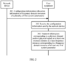
- FIG. 2 is a schematic communication diagram of a resource indication method according to an embodiment of the present invention.
- the method includes step 201 to step 203.
- a network device sends configuration information to user equipment, where the configuration information includes allocation information of frequency domain resources of a plurality of first system parameters.
- the plurality of first system parameters are system parameters supported by the network device, and any one of the plurality of first system parameters includes at least one of a subcarrier spacing size, a cyclic prefix CP type, or a symbol quantity corresponding to a time unit type.
- the CP type is determined based on CP overheads, and the time unit type may be a subframe in an LTE system, or a slot, a mini-slot, an aggregated slot, and an aggregated mini-slot in an NR system.
- a symbol includes a symbol part and a CP part. In the case of the same CP overheads, a smaller subcarrier spacing indicates a longer symbol part, to be specific, a larger symbol quantity corresponding to the time unit type.
- the subcarrier spacing size, the CP type, and the symbol quantity corresponding to the time unit type are three elements of a system parameter, and any one element can reflect the system parameter.
- a subcarrier spacing size supported by the NR may be 15 ⁇ 2 n kHz ( n ⁇ -2,-1,K,5 ⁇ , corresponding to a subcarrier spacing interval [3.75kHz,480kHz]).
- a value range of n may not be limited to a range from -2 to 5.
- the plurality of first system parameters may include a plurality of different subcarrier spacing sizes, such as 15 kHz and 30 kHz, or may include two or more same subcarrier spacing sizes, such as two 15 kHz subcarrier spacings.
- the network device allocates frequency domain resources to the plurality of first system parameters, to obtain allocation information of the frequency domain resources of the plurality of first system parameters.
- a specific method for allocating, by the network device, the frequency domain resources to the plurality of first system parameters is not limited herein, and the allocation method is determined by the network device.
- a same frequency domain resource may be allocated to two or more first system parameters, or different frequency domain resources may be allocated to the plurality of first system parameters.
- the network device may divide a system frequency domain resource (system bandwidth) based on a reference system parameter, and in this embodiment of the present invention, the reference system parameter is named a second system parameter.
- the second system parameter includes a subcarrier spacing size.
- the subcarrier spacing size of the second system parameter may be a default, or may be autonomously set by the network device, and a specific value is one of 15 ⁇ 2 n kHz.
- An identifier of the second system parameter may be notified to the user equipment. To be specific, the subcarrier spacing size of the second system parameter is notified.
- the network device does not notify the user equipment of the default subcarrier spacing size, because the default subcarrier spacing size may be predefined and learned by default by the network device and the user equipment.
- the default subcarrier spacing size is 15 kHz for initial access, or is a largest subcarrier spacing of 60 kHz that is supported by a data channel in a sub 6 GHz scenario.
- the network device notifies the user equipment of the identifier of the second system parameter by using higher layer or physical layer signaling.
- the higher layer signaling may include a master information block (Master Information Block, MIB), a system information block (System Information Block, SIB), a random access response message (Msg. 2), a message 4 (Msg. 4), and the like.
- the physical layer signaling may include DCI and the like.
- the network device may send the configuration information to the user equipment by using a Uu interface shown in FIG. 1 , where the configuration information includes allocation information of frequency domain resources of the plurality of first system parameters, and is used to indicate the frequency domain resources of the plurality of first system parameters.
- the configuration information further includes the identifier of the second system parameter, so that the user equipment divides a system band resource based on the second system parameter.
- the configuration information further includes identifiers of the plurality of first system parameters, specifically including identifiers of all first system parameters, and different first system parameters are corresponding to different identifiers.
- the configuration information is used to indicate allocation information of frequency domain resources corresponding to different first system parameters, and a correspondence between the different first system parameters and the allocation information of the frequency domain resources may be one-to-one.
- different first system parameters occupy different frequency domain resources.
- a correspondence between different first system parameters and the allocation information of the frequency domain resources may be many-to-one.
- two or more first system parameters may occupy a same frequency domain resource.
- the configuration information is common-level downlink control information, and a common level may be a cell level or a UE group level.
- the common-level downlink control information is common downlink control information that a cell user and a user in a UE group need to detect, and is separately located in common search space over a downlink control channel and search space in the UE group.
- the receiving party needs to perform error detection before receiving the data.
- the receiving party actually receives the data only when a detection result is correct.
- detection manners include a parity check, an Internet check, a cyclic redundancy check (Cyclic Redundancy Check, CRC), and the like.
- CRC Cyclic Redundancy Check
- the CRC is used to detect the common-level downlink control information.
- the CRC is a hash function that generates a short check code with fixed bits based on data such as a network data packet or a computer file, and is mainly used to detect or check an error that possibly occurs during data transmission or after data storage.
- the CRC on the common-level downlink control information is scrambled by using a cell or UE group common identifier.
- the cell common identifier is common information of users in the cell that is predefined or that is configured by using higher layer signaling, and includes a physical cell identifier (Physical Cell Identity, PCI), a hyper-cell identifier (hyper-cell Identity), a radio network temporary identifier (Radio Network Temporary Identity, RNTI), and the like.
- the UE group common identifier is common information of users in the UE group.
- the CRC on the common-level downlink control information is scrambled by using an identifier of the first system parameter.
- Performing scrambling by using the identifier of the first system parameter can indirectly indicate the identifier of the first system parameter.
- each first system parameter has a different identifier.
- the identifier of each first system parameter is corresponding to one piece of common-level downlink control information.
- the CRC on each piece of common-level downlink control information is scrambled by using an identifier of a corresponding first system parameter.
- the common-level downlink control information for the user equipment, scrambling can be performed only by using an identifier of a first system parameter supported by the user equipment. There may be one or more first system parameters supported by the user equipment. Because the CRC is scrambled by using the identifier of the first system parameter, in this case, the configuration information does not need to indicate the identifier of the first system parameter again. Therefore, a size of the common-level downlink control information may be reduced, and complexity of blind detection for the UE may be reduced.
- a frozen bit of the common-level downlink control information is the cell common identifier.
- a frozen bit is a polar (Polar) code
- some channels with better channel quality are selected from N channels as information transmission channels, and the remaining channels are used as frozen bit transmission channels, which are generally used to transmit fixed information.
- a decoding process may be not convergent. In other words, decoding cannot be performed properly.
- a frozen bit of the common-level downlink control information is the identifier of the first system parameter.
- a frozen bit of each piece of common-level downlink control information is an identifier of a corresponding first system parameter.
- the configuration information is higher layer signaling
- the higher layer signaling is carried in dedicated radio resource control (Radio Resource Control, RRC) signaling, a system message, a random access response message (Msg.2), a message 4 (Msg.4), or a MAC control element (Control Element, MAC CE).
- RRC Radio Resource Control
- Msg.2 random access response message
- Msg.4 message 4
- MAC CE MAC control element
- the system message is a public message, similar to a broadcast message.
- contention-based random access has four messages Msg. 1 to Msg. 4.
- the Msg. 2 is a random access response message (Msg.
- the Msg. 4 is Contention Resolution (Msg. 4) that is sent by the base station to the UE based on Scheduled Transmission Containing (Msg. 1) sent by the UE.
- the MAC CE is a control element or a control particle at a media access control layer.
- the following uses two examples to describe the configuration information, and both of the two examples use the downlink resource allocation type 2 for description. However, in the two examples, RBs instead of VRBs are consecutively allocated.
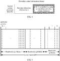
- FIG. 3 is a schematic diagram of a downlink control information format according to an embodiment of the present invention. As shown in FIG. 3 , a CRC in the DCI format is scrambled by using a cell common identifier.
- a first field in FIG. 3 is used to indicate an identifier of the second system parameter.
- a quantity of bits occupied by the field is ⁇ log 2 K ⁇ , where K represents a total quantity of first system parameters supported by the network device.
- a method for reducing overheads is that a value of K is related to a system working frequency.
- first system parameters supported by the network device include corresponding subcarrier spacings of 15 kHz, 30 kHz, and 60 kHz, and in this case, the value of K is 3 and the quantity of bits occupied by the field is 2.
- a second field in FIG. 3 is an area shown by left slash lines
- a third field is an area shown by grid lines
- an (N+1) th field is an area shown by right slash lines.
- Each of fields from the second field to the (N+1) th field includes two subfields.
- a first subfield of the field represents an identifier of a first system parameter corresponding to a first subband.
- a quantity of bits occupied by the first subfield is ⁇ log 2 K ⁇ , where K represents a total quantity of first system parameters supported by the network device.
- a second subfield of the field represents resource allocation information 1 of the first system parameter corresponding to the first subband.
- a quantity of bits occupied by the second subfield is ⁇ log 2 N RB DL N RB DL + 1 / 2 ⁇ , where N RB DL represents a downlink system bandwidth.
- the second subfield of the field is a resource indicator value RIV, which is used to represent a start RB ( RB start ) of the first subband and a length ( L CRBs ) of consecutively allocated RBs.
- RIV resource indicator value
- the second subfield indicates the resource allocation information 1 of the first system parameter corresponding to the first subband.
- the configuration information includes an identifier of the first system parameter (an identifier of each first system parameter) and an identifier of the second system parameter, and the CRC of the configuration information is scrambled by using a cell common identifier.
- FIG. 4 is a schematic diagram of another downlink control information format according to an embodiment of the present invention.
- a CRC in the DCI format is scrambled by using an identifier n of a first system parameter.
- the identifier n of the first system parameter may represent an identifier of a first system parameter in a plurality of first system parameters.
- a first field in FIG. 4 is used to indicate an identifier of the second system parameter.
- a quantity of bits occupied by the field is ⁇ log 2 K ⁇ , where K represents a total quantity of first system parameters supported by the network device.
- a method for reducing overheads is that a value of K is related to a system working frequency.
- first system parameters supported by the network device include corresponding subcarrier spacings of 15 kHz, 30 kHz, and 60 kHz, and in this case, the value of K is 3 and the quantity of bits occupied by the field is 2.
- a second field in FIG. 4 is used to indicate resource allocation information n of a first system parameter corresponding to a first subband, and a quantity of bits occupied by the field is ⁇ log 2 N RB DL N RB DL + 1 / 2 ⁇ .
- the field is a resource indicator value RIV, which is used to indicate a start RB ( RB start ) of the first subband and a length ( L CRBs ) of consecutively allocated RBs.
- RIV resource indicator value
- one piece of DCI is corresponding to one CRC scrambled by using an identifier of a first system parameter
- one DCI is corresponding to one piece of resource allocation information of a first system parameter.
- the corresponding resource allocation information is determined based on the identifier of the first system parameter in the scrambled CRC.
- the configuration information includes an identifier of the second system parameter, and a CRC of the configuration information is scrambled by using the identifier of the first system parameter.
- the resource allocation information in FIG. 3 and FIG. 4 is allocation information of a frequency domain resource, and is consecutive in frequency domain based on the downlink resource allocation type 2.
- a resource indicated by the resource allocation information varies and is determined based on a specific resource allocation type.
- the resource may be consecutive or not consecutive in frequency domain.
- the user equipment receives the configuration information sent by the network device.
- Allocation information of a frequency domain resource of the first system parameter, the first system parameter, and the second system parameter are used to determine the frequency domain resource of the first system parameter.
- a frequency domain resource of any one of the plurality of first system parameters is determined.
- a frequency domain resource of each first system parameter may be determined, and then frequency domain resources of the plurality of first system parameters may be determined.
- the user equipment divides a system frequency domain resource based on the second system parameter. For example, if a subcarrier spacing size corresponding to the second system parameter is 60 kHz, the user equipment divides the system frequency domain resource based on the 60 kHz and numbers the system frequency domain resource from 0 to N-1.
- the user equipment determines the frequency domain resource of the first system parameter based on the allocation information of the frequency domain resource of the first system parameter, the first system parameter, and the system frequency domain resource obtained after division based on the second system parameter. In other words, the user equipment determines the frequency domain resource allocated by the network device to the first system parameter.
- the first system parameter is one of the plurality of first system parameters.
- the user equipment when receiving the DCI, the user equipment performs corresponding blind detection based on a scrambling manner of the DCI; or when receiving the DCI, the user equipment performs decoding based on a frozen bit of the DCI.
- the user equipment blindly detects the DCI by using the cell common identifier, so as to obtain each field shown in FIG. 3 .
- the user equipment determines the second system parameter based on the first field, divides the system frequency domain resource based on the second system parameter and numbers the system frequency domain resource.
- Identifiers of all first system parameters are represented by a same quantity of bits, namely, ⁇ log 2 K ⁇ . Therefore, the plurality of first system parameters supported by the network device may be numbered according to a predefined rule, for example, be numbered in ascending order of subcarrier spacings.
- the user equipment determines an identifier of a first system parameter corresponding to a first subband based on a value of bits ⁇ log 2 K ⁇ of the first subfield in the second field, and the user equipment further determines a start RB RB start ref in the first subband and a length L CRBs ref of consecutively allocated RBs based on a value of bits ⁇ log 2 N RB DL N RB DL + 1 / 2 ⁇ of the second subfield in the second field. In other words, the user equipment determines allocation information of a frequency domain resource of the first system parameter corresponding to the first subband.
- the user equipment determines identifiers of the first system parameters corresponding to a second subband, a third subband, and the like respectively based on a third field, a fourth field, and the like, and determines a respective start RB of each subband and a length of consecutively allocated RBs.
- FIG. 5 is a schematic diagram of frequency band division information obtained by user equipment based on FIG. 3 .
- the frequency band allocation information separately indicates allocation information of a frequency domain resource of a first system parameter corresponding to subcarrier spacings of 15 kHz, 60 kHz, and 30 kHz, and the subcarrier spacing of the second system parameter is 60 kHz.
- the user equipment blindly detects DCI by using the identifier of the first system parameter supported by the user equipment.
- the user equipment can blindly detect the DCI properly only when the identifier of the first system parameter required by the user equipment is the same as the identifier of the first system parameter corresponding to the second field, so as to obtain the fields shown in FIG. 4 .
- the user equipment determines the second system parameter based on the first field, divides the system frequency domain resource based on the second system parameter and numbers the system frequency domain resource. In the case of proper blind detection, the user equipment determines allocation information of a frequency domain resource of a first system parameter supported by the user equipment based on the second field.
- FIG. 6 is a schematic diagram of frequency band division information obtained by user equipment based on FIG. 4 .
- a subcarrier spacing of the second system parameter is 60 kHz
- a subcarrier spacing size of a first system parameter supported by the user equipment is 30 kHz
- the user equipment obtains only a start RB of a subband corresponding to 30 kHz and a length of consecutively allocated RBs. If there is no extra signaling indication, the user equipment considers other frequency bands as blank resources.
- DCI in example 2 is relatively small, and can reduce complexity of blind detection for the UE to some extent. If the UE needs to obtain allocation information of a frequency domain resource of another first system parameter, the UE needs to attempt identifiers of a plurality of first system parameters, and a quantity of detection times increases to some extent.
- the user equipment may determine frequency domain resources of one or more first system parameters based on a requirement. For example, for FIG. 5 , the user equipment may determine frequency domain resources of the plurality of first system parameters, and for FIG. 6 , the user equipment may determine a frequency domain resource of a first system parameter supported by the user equipment, and there may be one or more first system parameters supported by the user equipment.
- the user equipment transmits information corresponding to a physical channel and/or information corresponding to a physical signal on at least one resource element in a time-frequency resource corresponding to a frequency domain resource of at least one of the plurality of first system parameters.
- the user equipment After determining the frequency domain resource of the at least one first system parameter, the user equipment transmits the information corresponding to the physical channel and/or the information corresponding to the physical signal on the at least one resource element in the time-frequency resource corresponding to the frequency domain resource.
- the frequency domain resource of the at least one first system parameter it should be understood that, for FIG. 6 , if the user equipment supports one first system parameter, the frequency domain resource of the at least one first system parameter is a frequency domain resource corresponding to the first system parameter, and if the user equipment supports two or more first system parameters, the frequency domain resource of the at least one first system parameter is frequency domain resources corresponding to the two or more first system parameters; for FIG. 5 , the frequency domain resource of the at least one first system parameter is frequency domain resources corresponding to the plurality of first system parameters.
- one subframe includes two slots (slot), and one slot includes seven symbols.
- a horizontal direction of the RE represents time domain resources, and a vertical direction of the RE represents frequency domain resources.
- the user equipment After determining the frequency domain resource corresponding to the at least one first system parameter, the user equipment determines a time-frequency resource corresponding to the at least one first system parameter based on the frequency domain resource corresponding to the at least one first system parameter. In this case, the time-frequency resource corresponding to the at least one first system parameter includes at least one resource element.
- the user equipment performs uplink or downlink information transmission on the at least one resource element.
- the information may be the information corresponding to the physical channel, may be the information corresponding to the physical signal, or may be the information corresponding to the physical channel and the information corresponding to the physical signal.
- a resource element corresponding to the physical channel is used to carry information from a higher layer, and the physical channel may include a physical uplink/downlink control channel, a physical uplink/downlink shared channel, a physical random access channel, a physical broadcast channel, and a physical multicast channel.
- a resource element corresponding to the physical signal is used for physical layer transmission, and does not carry the information from the higher layer.
- the physical signal may include a reference signal, a synchronization signal, and a discovery signal.
- the user equipment when blindly detecting or decoding corresponding frequency domain resource allocation information by using a first system parameter supported by the user equipment, the user equipment determines a corresponding frequency domain resource, and transmits the information corresponding to the physical channel and/or the information corresponding to the physical signal on at least one resource element of a time-frequency resource corresponding to the frequency domain resource.
- the network device sends, to the user equipment, the configuration information that includes the allocation information of the frequency domain resources of the plurality of first system parameters, so as to indicate the frequency domain resources corresponding to the plurality of first system parameters, so that the user equipment transmits the information corresponding to the physical channel and/or the information corresponding to the physical signal on at least one resource element of a time-frequency resource corresponding to a required frequency domain resource, and the resource allocation status in the co-existence scenario of the plurality of system parameters is indicated.
- RB resources In the LTE system, dynamic scheduling of RB resources is implemented on an eNB side, and "RB resources" herein are actually VRBs (Virtual RBs) rather than PRBs.
- VRB Virtual RBs
- the simplest mapping relationship is that a location of the VRB is the same as a location of the PRB, and there is a one-to-one correspondence between the location of the VRB and the location of the PRB.
- Another relatively complex relationship is that there is no one-to-one correspondence between the VRB and the PRB, but the location of the PRB can be explicitly deduced by using the VRB depending on a specific mapping relationship.
- the former simple relationship of one-to-one correspondence is centralized resource allocation, whereas the latter relatively complex mapping relationship is distributed resource allocation.
- the eNB side may use different allocation manners based on different scenarios.
- the centralized resource allocation can improve a rate of UE and a throughput of an entire cell, and the distributed resource allocation can improve transmission reliability.
- a downlink VRB has two resource mapping manners: a centralized VRB resource mapping manner and a distributed VRB resource mapping manner.
- a VRB pair and a PRB pair are in a one-to-one correspondence.
- the location of the VRB is the location of the PRB.
- An RB resource block sequence number n PRB n VRB , ranging from 0 to N RB DL ⁇ 1 .
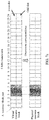
- FIG. 7a is a location relationship between the PRB and the VRB when a VRB resource is allocated in a centralized manner in a bandwidth of 5 MHz.
- the VRB pair and the PRB pair are not in a one-to-one correspondence, the consecutive VRB sequence numbers are mapped to nonconsecutive PRB sequence numbers, and two slots in one subframe have different mapping relationships (as shown in FIG. 7b ).
- “distributed" resource allocation is achieved. Regardless of whether the consecutive VRB pairs are mapped to the nonconsecutive PRB pairs, or each PRB pair is separated and two RB resources of one PRB pair are transmitted at a specific frequency spacing (which may be considered as slot-based frequency hopping (hopping)), the purpose is to achieve a diversity effect in frequency.
- FIG. 7b is a schematic diagram of a distributed resource allocation process in which a downlink bandwidth is 5 MHz.
- the diagram is used merely to help understand a distributed process, and does not represent that an actual mapping location of the PRB is the same as that shown in FIG. 7b .
- the diagram is simple and intuitive, and can describe this process well. The following specifically describes this mapping relationship from a protocol perspective, or how to obtain the actual mapping location of the PRB pair from the VRB pair.
- Interleaving includes: (1) determining a value of N gap , a value of P , and a quantity of VRB pairs, where N gap is used to indicate a frequency offset between an RB pair, this value is measured in a unit of a quantity of RBs, and varies with a system bandwidth, and once the system bandwidth is determined, this value is determined; P is used to indicate a size of an RBG, where the value of P is related to the system bandwidth; (2) determining a VRB interleaving matrix: "horizontal placement”; and (3) determining the PRB corresponding to the VRB: “column fetching".
- Step 2 Frequency hopping between slots includes: for a same VRB number, an RB in an odd slot is offset by ⁇ VRB /2 in the VRB interleaving unit on the basis of an even slot.
- Selection of parameters in the distributed mapping from the VRB to the PRB depends on the system bandwidth.
- the RBs cannot be numbered uniformly.
- using the foregoing distributed mapping causes a disorder of RB numbers corresponding to different system parameters.
- An intuitive solution is that the foregoing distribution is performed only within the bandwidth occupied by the same system parameter, and is not performed across system parameters.
- the UE needs to clearly know a frequency domain resource location corresponding to each system parameter, including a frequency domain start RB and a frequency domain width.
- the embodiments of the present invention provide the method for mapping a virtual resource block to a physical resource block, the network device, and the user equipment, which are applicable to the co-existence scenario of the plurality of system parameters, and can indicate resource allocation in the co-existence scenario of the plurality of system parameters.
- mapping method is a detailing process of step 203 in the embodiment shown in FIG. 2 .
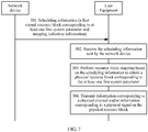
- FIG. 7 is a schematic communication diagram of a method for mapping a virtual resource block to a physical resource block according to an embodiment of the present invention.
- the method includes step 301 and step 302.
- a network device sends scheduling information to user equipment, where the scheduling information includes a first virtual resource block corresponding to at least one first system parameter and mapping indication information.
- the scheduling information may be DCI, and a format of the DCI includes a mapping manner indication bit.
- the bit indicates the mapping indication information, and is used to instruct the user equipment to perform resource block mapping in an indicated mapping manner.
- the indicated mapping manner may be centralized mapping or new distributed mapping, and the new distributed mapping is first distributed mapping and then centralized mapping.
- the first virtual resource block corresponding to the at least one first system parameter includes numbers of the first virtual resource blocks corresponding to all first system parameters.
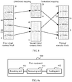
- FIG. 8 is a schematic diagram of example mapping according to the embodiment shown in FIG. 7 .
- the at least one first system parameter includes two first system parameters corresponding to a subcarrier spacing of 15 kHz and a first system parameter corresponding to a subcarrier spacing of 30 kHz. Numbers of the first virtual resource blocks corresponding to the two first system parameters corresponding to the subcarrier spacing of 15 kHz are respectively 0 to 19 and 20 to 49, and numbers of the first virtual resource blocks corresponding to the first system parameter corresponding to the subcarrier spacing of 30 kHz are 0 to 39.
- the user equipment receives the scheduling information sent by the network device.
- the user equipment performs resource block mapping based on the scheduling information to obtain a physical resource block corresponding to the at least one first system parameter.
- the user equipment maps the first virtual resource blocks corresponding to all first system parameters to corresponding physical resource blocks in the centralized mapping manner and based on numbers of the first virtual resource blocks corresponding to all the first system parameters.
- numbers of the first virtual resource blocks corresponding to the first system parameter with a subcarrier spacing size of 30 kHz are 0 to 39, and a quantity of occupied RBs is 40.
- n VRB ,2 indicates a number of the second virtual resource block.
- numbers of the first virtual resource blocks corresponding to the first system parameter with a subcarrier spacing size of 30 kHz are 0 to 39, and numbers of the mapped second virtual resource blocks are 0 to 39.
- Numbers of the first virtual resource blocks corresponding to the two first system parameters with a subcarrier spacing size of 15 kHz are respectively 0 to 19 and 20 to 49, and numbers of the mapped second virtual resource blocks are consecutive numbers from 0 to 49.
- physical resource blocks corresponding to two first system parameters with a subcarrier spacing size of 15 kHz are not consecutive and are uniformly numbered 0 to 49. Numbers of the physical resource blocks corresponding to the first system parameter with a subcarrier spacing size of 30 kHz are 0 to 39.
- step 303 is performed within a segment of bandwidth.
- the bandwidth may be a system bandwidth, or may be a segment of consecutive bandwidths within the system bandwidth, or may be a segment of consecutive bandwidths that is formed by connecting a plurality of segments of consecutive bandwidths in a manner from a low frequency to a high frequency.
- the user equipment transmits information corresponding to a physical channel and/or information corresponding to a physical signal on the physical resource block.
- the user equipment transmits the information corresponding to the physical channel and/or the information corresponding to the physical signal on some or all resource blocks of the physical resource blocks.
- mapping may be performed in a manner of combining a distributed mapping manner and a centralized mapping manner. This is applicable to a co-existence scenario of at least one system parameter, and can indicate resource allocation in the co-existence scenario of the at least one system parameter.
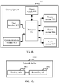
- FIG. 9a is a schematic structural diagram of user equipment according to an embodiment of the present invention.
- the user equipment 900 includes a receiving unit 901 and a sending unit 902.
- the receiving unit 901 is configured to receive configuration information sent by a network device, where the configuration information includes allocation information of frequency domain resources of a plurality of first system parameters.
- the sending unit 902 is further configured to transmit information corresponding to a physical channel and/or information corresponding to a physical signal on at least one resource element in a time-frequency resource corresponding to a frequency domain resource of at least one of the plurality of first system parameters.
- the first system parameter includes at least one of parameters such as a first subcarrier spacing size, a cyclic prefix length, a transmission time interval length, a symbol length, and a symbol quantity.
- the frequency domain resource of the first system parameter is determined by allocation information of the frequency domain resource of the first system parameter, the first system parameter, and a second system parameter, where the second system parameter includes a second subcarrier spacing size.
- the plurality of first system parameters are system parameters supported by the network device, and the second system parameter is a reference system parameter for dividing a system frequency domain resource.
- the configuration information further includes an identifier of the second system parameter.
- the configuration information further includes an identifier of the first system parameter.
- the configuration information is common-level downlink control information
- a cyclic redundancy check on the common-level downlink control information is scrambled by using a cell common identifier, or a frozen bit of the common-level downlink control information is the cell common identifier.
- the configuration information is common-level downlink control information
- a cyclic redundancy check on the common-level downlink control information is scrambled by using an identifier of the first system parameter, or a frozen bit of the common-level downlink control information is the identifier of the first system parameter.
- the configuration information is higher layer signaling
- the higher layer signaling is carried in dedicated radio resource control signaling, a system message, a random access response message, a message 4, or a media access control control element.
- the receiving unit 901 is configured to perform step 202 in the embodiment shown in FIG. 2 , and is further configured to perform step 302 in the embodiment shown in FIG. 7 .
- the sending unit 902 is configured to perform step 203 in the embodiment shown in FIG. 2 , and is further configured to perform step 304 in the embodiment shown in FIG. 7 .
- the user equipment 900 further includes a processing unit 903, configured to perform step 303 in the embodiment shown in FIG. 7 .
- the processing unit 903 may be a processor or a controller, for example, may be a central processing unit (Central Processing Unit, CPU), a general-purpose processor, a digital signal processor (Digital Signal Processor, DSP), an application-specific integrated circuit (Application Specific Integrated Circuit, ASIC), a field programmable gate array (Field Programmable Gate Array, FPGA), or another programmable logic device, a transistor logic device, a hardware component, or any combination thereof.
- the controller/processor may implement or execute various example logical blocks, modules, and circuits described with reference to content disclosed in the present invention.
- the processor may be a combination of processors implementing a computing function, for example, a combination of one or more microprocessors, or a combination of the DSP and a microprocessor.
- the receiving unit 901 and the sending unit 902 may be a transceiver, a transceiver circuit, a communications module, or the like.
- the user equipment in the embodiments of the present invention may be user equipment shown in FIG. 9b .
- the user equipment 910 includes a power supply 911, a user interface 912, a communications module 913, a processor 914, a display system 919, a sensor system 916, and an audio system 917.
- the user equipment 910 may represent the user equipment in FIG. 1 , or may represent an electronic device such as a motor vehicle, a non-motor vehicle, another communications device on a road, or an intelligent household appliance.
- a structure of the user equipment shown in FIG. 9b does not constitute a limitation on the embodiments of the present invention.
- the power supply 911 supplies electric power for implementing various functions of the user equipment 910.
- the user interface 912 is configured to connect the user equipment 910 to another device or apparatus, so as to implement communication or data transmission between the another device or apparatus and the user equipment 910.
- the communications module 913 is configured to implement communication or data transmission between the user equipment 910 and a network device such as a base station or a satellite, and is further configured to implement communication or data transmission between the user equipment 910 and another user equipment. Being applied to this embodiment of the present invention, the communications module 913 is configured to implement functions of the receiving unit 901 and the sending unit 902 shown in FIG. 9a .
- the processor 914 may implement or execute various example logical blocks, modules, and circuits described with reference to content disclosed in the present invention.
- the processor 914 is configured to implement a function of the processing unit 903 shown in FIG. 9a .
- the display system 919 is configured to output and display information and receive a user-input operation.
- the sensor system 916 includes various sensors, such as a temperature sensor or a distance sensor.
- the audio system 917 is configured to output an audio signal.
- FIG. 10a is a schematic structural diagram of a network device according to an embodiment of the present invention.
- the network device 1000 includes a sending unit 1001.
- the sending unit 1001 is configured to send configuration information to user equipment, where the configuration information includes allocation information of frequency domain resources of a plurality of first system parameters, and at least one resource element in a time-frequency resource corresponding to a frequency domain resource of at least one of the plurality of first system parameters is used by the user equipment to transmit information corresponding to a physical channel and/or information corresponding to a physical signal.
- the first system parameter includes at least one of parameters such as a first subcarrier spacing size, a cyclic prefix length, a transmission time interval length, a symbol length, and a symbol quantity.
- the network device 1000 further includes a processing unit 1002, configured to allocate frequency domain resources to the plurality of first system parameters, to obtain allocation information of the frequency domain resources of the plurality of first system parameters.
- the sending unit 1001 is configured to perform step 201 in the embodiment shown in FIG. 2 , and is further configured to perform step 301 in the embodiment shown in FIG. 7 .
- the processing unit 1002 may be a processor or a controller, for example, may be a CPU, a general-purpose processor, a DSP, an ASIC, an FPGA, or another programmable logic device, a transistor logic device, a hardware component, or any combination thereof.
- the controller/processor may implement or execute various example logical blocks, modules, and circuits described with reference to content disclosed in the present invention.
- the processor may be a combination of processors implementing a computing function, for example, a combination of one or more microprocessors, or a combination of the DSP and a microprocessor.
- the sending unit 1001 may be a transceiver, a transceiver circuit, a communications interface, or the like.
- the network device in this embodiment of the present invention may be a network device shown in FIG. 10b .
- the network device 1010 includes a processor 1011, a transceiver 1012, and an antenna. It should be noted that, in actual application, a quantity of the transceivers 1012 is not limited to two, a quantity of the antennas is also not limited to two, and a structure of the network device 1010 does not constitute a limitation on the embodiments of the present invention.
- the processor 1011 mainly includes four components: a cell controller, a voice channel controller, a signaling channel controller, and a multi-path interface used for extension.
- the processor 1011 is responsible for management of all mobile communications interfaces, which is mainly allocation, release, and management of a radio channel. Being applied to this embodiment of the present invention, the processor 1011 is configured to implement a function of the processing unit 1002 shown in FIG. 10a .
- the transceiver 1012 includes a receiver and a transmitter. For user equipment, the transceiver may transmit uplink data by using the transmitter and receive downlink data by using the receiver. Being applied to this embodiment of the present invention, the transceiver 1012 is configured to implement a function of the sending unit 1001 shown in FIG. 10a .
- An embodiment of the present invention further provides a resource indication system, including the user equipment shown in FIG. 9a and the network device shown in FIG. 10a , or the user equipment shown in FIG. 9b and the network device shown in FIG. 10b .
- a person of ordinary skill in the art may understand that all or some of the processes of the methods in the embodiments may be implemented by a computer program requesting related hardware.
- the program may be stored in a computer readable storage medium. When the program runs, the processes of the methods in the embodiments are performed.
- the foregoing storage medium may include: a magnetic disk, an optical disc, a read-only memory (Read-Only Memory, ROM), or a random access memory (Random Access Memory, RAM).
Landscapes
- Engineering & Computer Science (AREA)
- Signal Processing (AREA)
- Computer Networks & Wireless Communication (AREA)
- Mobile Radio Communication Systems (AREA)
Applications Claiming Priority (2)
| Application Number | Priority Date | Filing Date | Title |
|---|---|---|---|
| CN201710010466.3A CN108282870B (zh) | 2017-01-06 | 2017-01-06 | 一种资源指示方法、用户设备及网络设备 |
| PCT/CN2017/120281 WO2018127021A1 (zh) | 2017-01-06 | 2017-12-29 | 一种资源指示方法、用户设备及网络设备 |
Publications (3)
| Publication Number | Publication Date |
|---|---|
| EP3554155A1 true EP3554155A1 (de) | 2019-10-16 |
| EP3554155A4 EP3554155A4 (de) | 2019-12-25 |
| EP3554155B1 EP3554155B1 (de) | 2023-09-20 |
Family
ID=62789263
Family Applications (1)
| Application Number | Title | Priority Date | Filing Date |
|---|---|---|---|
| EP17889793.0A Active EP3554155B1 (de) | 2017-01-06 | 2017-12-29 | Verfahren und benutzervorrichtung zum anzeigen von ressourcen |
Country Status (5)
| Country | Link |
|---|---|
| US (1) | US10979194B2 (de) |
| EP (1) | EP3554155B1 (de) |
| JP (1) | JP2020504546A (de) |
| CN (1) | CN108282870B (de) |
| WO (1) | WO2018127021A1 (de) |
Families Citing this family (24)
| Publication number | Priority date | Publication date | Assignee | Title |
|---|---|---|---|---|
| CN108282870B (zh) * | 2017-01-06 | 2021-04-20 | 华为技术有限公司 | 一种资源指示方法、用户设备及网络设备 |
| US11212682B2 (en) | 2017-06-27 | 2021-12-28 | Telefonaktiebolaget Lm Ericsson (Publ) | Shared channel remapping in a multiple radio access technology co-existence scenario |
| US20190260435A1 (en) * | 2018-02-17 | 2019-08-22 | Mediatek Inc. | Uplink Transmission Schemes In Mobile Communications |
| CN110636617B (zh) * | 2018-06-22 | 2022-04-05 | 华为技术有限公司 | 一种参数配置方法及装置 |
| US10999023B2 (en) * | 2018-07-16 | 2021-05-04 | Mediatek Singapore Pte. Ltd. | Method and apparatus for frequency domain resource allocation when frequency hopping is enabled in mobile communications |
| JP7237486B2 (ja) * | 2018-07-31 | 2023-03-13 | シャープ株式会社 | 端末装置、基地局装置、および、通信方法 |
| CN111294972B (zh) * | 2018-12-10 | 2021-12-24 | 上海朗帛通信技术有限公司 | 一种被用于无线通信的用户设备、基站中的方法和装置 |
| KR20240071415A (ko) | 2019-01-04 | 2024-05-22 | 텔레폰악티에볼라겟엘엠에릭슨(펍) | 초-신뢰 저-레이턴시 통신을 위한 반복 |
| CN113330797B (zh) * | 2019-01-11 | 2024-08-16 | 瑞典爱立信有限公司 | 用于免许可频谱中上行链路传输的资源分配 |
| EP3909348B1 (de) * | 2019-01-11 | 2024-04-17 | Telefonaktiebolaget LM Ericsson (publ) | Zuweisung von frequenzbereichsressourcen zur übertragung mehrerer quellen |
| CN113366779B (zh) * | 2019-01-31 | 2023-06-06 | 华为技术有限公司 | 一种信息传输方法、相关设备及系统 |
| CN113632556B (zh) | 2019-03-28 | 2025-04-18 | 松下电器(美国)知识产权公司 | 通信装置、通信方法、基站和集成电路 |
| US11082984B2 (en) * | 2019-06-24 | 2021-08-03 | Qualcomm Incorporated | Frequency domain resource allocation for frequency division multiplexing schemes with single downlink control information associated with multiple transmission configuration indication states |
| CN114342530A (zh) | 2019-07-03 | 2022-04-12 | 瑞典爱立信有限公司 | 针对交错传输的频域资源分配 |
| CN111836378B (zh) * | 2019-08-15 | 2023-07-25 | 维沃移动通信有限公司 | 一种频域资源分配方法、网络侧设备及终端 |
| CN113259294B (zh) * | 2020-02-12 | 2026-03-13 | 夏普株式会社 | 由用户设备执行的方法以及用户设备 |
| US12021827B2 (en) * | 2020-03-16 | 2024-06-25 | Nokia Technologies Oy | Apparatus, method and computer program to influence 3GPP terminals on preferences between multiple recursive DNS servers |
| US12471091B2 (en) | 2020-04-24 | 2025-11-11 | Beijing Xiaomi Mobile Software Co., Ltd. | Wearable device and method for wearable device to acquire communication resources |
| CN119697733A (zh) * | 2020-04-29 | 2025-03-25 | 华为技术有限公司 | 通信方法和通信装置 |
| CN114143801B (zh) * | 2020-09-04 | 2024-03-22 | 上海朗帛通信技术有限公司 | 一种被用于无线通信的节点中的方法和装置 |
| EP4307790A4 (de) * | 2021-03-12 | 2024-12-04 | Ntt Docomo, Inc. | Kommunikationsvorrichtung und kommunikationsverfahren |
| TWI827939B (zh) * | 2021-06-09 | 2024-01-01 | 光寶科技股份有限公司 | 網路實體及資源配置方法 |
| CN116033578B (zh) * | 2022-09-28 | 2026-03-17 | 山东浪潮科学研究院有限公司 | 物理资源分配方法、装置、电子设备及存储介质 |
| CN120814315A (zh) * | 2023-06-08 | 2025-10-17 | Oppo广东移动通信有限公司 | 无线通信方法、第一设备和第二设备 |
Family Cites Families (20)
| Publication number | Priority date | Publication date | Assignee | Title |
|---|---|---|---|---|
| US9584354B2 (en) * | 2013-07-01 | 2017-02-28 | Nxp Usa, Inc. | Radio signal decoding and decoder |
| WO2015017969A1 (zh) * | 2013-08-05 | 2015-02-12 | 华为技术有限公司 | 带宽分配方法、装置及系统 |
| WO2015109609A1 (zh) * | 2014-01-27 | 2015-07-30 | 华为技术有限公司 | 一种窄带传输的方法、设备、基站及用户设备 |
| US10862634B2 (en) * | 2014-03-07 | 2020-12-08 | Huawei Technologies Co., Ltd. | Systems and methods for OFDM with flexible sub-carrier spacing and symbol duration |
| WO2016004634A1 (en) * | 2014-07-11 | 2016-01-14 | Mediatek Singapore Pte. Ltd. | Method for enb, ue uplink transmission and reception |
| CN105813199A (zh) * | 2014-12-30 | 2016-07-27 | 夏普株式会社 | 针对寻呼消息的资源分配方法及网络节点和用户设备 |
| CN107113155B (zh) * | 2015-01-15 | 2020-06-26 | 苹果公司 | 提供用于块单载波传输的灵活的保护间隔的装置和方法 |
| US10091713B2 (en) * | 2015-01-27 | 2018-10-02 | Qualcomm Incorporated | Numerology and frames for networks in the sub-1GHz (S1G) band |
| WO2016130175A1 (en) * | 2015-02-11 | 2016-08-18 | Intel IP Corporation | Device, system and method employing unified flexible 5g air interface |
| CN106304138A (zh) * | 2015-05-28 | 2017-01-04 | 中兴通讯股份有限公司 | 系统参数处理方法及装置 |
| US10038581B2 (en) * | 2015-06-01 | 2018-07-31 | Huawei Technologies Co., Ltd. | System and scheme of scalable OFDM numerology |
| US20160360550A1 (en) * | 2015-06-03 | 2016-12-08 | Qualcomm Incorporated | Low latency under time division duplex and flexible frequency division duplex |
| CN114158126B (zh) * | 2016-03-22 | 2025-08-12 | 中兴通讯股份有限公司 | 一种信息传输方法、装置和系统 |
| WO2018031664A1 (en) * | 2016-08-10 | 2018-02-15 | Idac Holdings, Inc. | Methods for flexible resource usage |
| EP3282623A1 (de) * | 2016-08-12 | 2018-02-14 | Panasonic Intellectual Property Corporation of America | Dynamische betriebsmittelzuteilung zwischen verschiedenen ofdm-numerologieschemen |
| ES2822344T3 (es) * | 2016-08-12 | 2021-04-30 | Asustek Comp Inc | Método y aparato para determinar un ancho de banda de numerología en un sistema de comunicación inalámbrica |
| KR102110639B1 (ko) * | 2016-09-30 | 2020-05-14 | 아서스테크 컴퓨터 인코포레이션 | 무선 통신 시스템에서 다수의 뉴머롤로지들을 위한 제어 채널을 수신하는 방법 및 장치 |
| EP3319263B1 (de) * | 2016-11-04 | 2020-10-14 | Mitsubishi Electric R&D Centre Europe B.V. | Resourceszuweisung mit unterschiedlichen numerologien in demselben band |
| RU2737792C1 (ru) * | 2016-12-23 | 2020-12-03 | Гуандун Оппо Мобайл Телекоммьюникейшнз Корп., Лтд. | Способ передачи информации, сетевое устройство и оконечное устройство |
| CN108282870B (zh) * | 2017-01-06 | 2021-04-20 | 华为技术有限公司 | 一种资源指示方法、用户设备及网络设备 |
-
2017
- 2017-01-06 CN CN201710010466.3A patent/CN108282870B/zh active Active
- 2017-12-29 JP JP2019536924A patent/JP2020504546A/ja active Pending
- 2017-12-29 EP EP17889793.0A patent/EP3554155B1/de active Active
- 2017-12-29 WO PCT/CN2017/120281 patent/WO2018127021A1/zh not_active Ceased
-
2019
- 2019-07-05 US US16/504,024 patent/US10979194B2/en active Active
Also Published As
| Publication number | Publication date |
|---|---|
| JP2020504546A (ja) | 2020-02-06 |
| US20190334680A1 (en) | 2019-10-31 |
| EP3554155B1 (de) | 2023-09-20 |
| US10979194B2 (en) | 2021-04-13 |
| WO2018127021A1 (zh) | 2018-07-12 |
| CN108282870A (zh) | 2018-07-13 |
| EP3554155A4 (de) | 2019-12-25 |
| CN108282870B (zh) | 2021-04-20 |
Similar Documents
| Publication | Publication Date | Title |
|---|---|---|
| US10979194B2 (en) | Resource indication method, user equipment, and network device | |
| JP6674589B1 (ja) | 狭帯域通信のための狭帯域時分割複信フレーム構造 | |
| EP3562239B1 (de) | Kommunikationsverfahren und -vorrichtung | |
| CN109644450B (zh) | 时频资源传输方向的配置方法和装置 | |
| JP6939796B2 (ja) | 狭帯域IoT通信システムにおけるサブキャリア間隔のシグナリング | |
| EP3243341B1 (de) | Ressourcenzuweisungsentwurf für kostengünstige maschinenkommunikation | |
| CN111357379A (zh) | 用于早期数据传输的物理层增强 | |
| JP2019532537A (ja) | 車両対車両通信のための復調基準信号設計 | |
| CN110447202A (zh) | 针对使用窄带通信的一个或多个上行链路传输的调度请求 | |
| CN111183608A (zh) | 无线通信系统的数据发送方法和接收方法及使用该方法的设备 | |
| JP2020504472A (ja) | 混合ヌメロロジーをサポートするシステムのためのシーケンス生成 | |
| EP3442151B1 (de) | Datenverarbeitungsverfahren, vorrichtung und system | |
| US9167584B2 (en) | Method and apparatus for allocating resources in a multi-node system | |
| EP3257308A1 (de) | Vorrichtung, system und verfahren mit vereinheitlichter flexibler 5g-luftschnittstelle | |
| WO2010016737A2 (en) | Method and device for allocating resources in multiple frequency band system | |
| KR20220041837A (ko) | 물리적 다운링크 제어 채널을 수신하기 위한 방법 및 장치 | |
| CN104168610B (zh) | 一种传输下行信号的方法、装置及终端设备 | |
| CN104335639A (zh) | 用于小区内设备到设备(d2d)通信的探测参考信号(srs)机制 | |
| EP4021114A1 (de) | Srs-übertragungsverfahren und -vorrichtung | |
| EP4593493A1 (de) | Uplink-übertragungsverfahren und kommunikationsvorrichtung | |
| CN109923917B (zh) | 用于指示数字基本配置的方法和设备 | |
| CN109698738B (zh) | 通信方法和通信装置 | |
| WO2018185093A1 (en) | Supporting mixed numerologies | |
| EP4572482A1 (de) | Kommunikationsvorrichtung und kommunikationsverfahren | |
| CN121729958A (zh) | 用于pdcch的发送和接收的方法及其装置 |
Legal Events
| Date | Code | Title | Description |
|---|---|---|---|
| STAA | Information on the status of an ep patent application or granted ep patent |
Free format text: STATUS: THE INTERNATIONAL PUBLICATION HAS BEEN MADE |
|
| PUAI | Public reference made under article 153(3) epc to a published international application that has entered the european phase |
Free format text: ORIGINAL CODE: 0009012 |
|
| STAA | Information on the status of an ep patent application or granted ep patent |
Free format text: STATUS: REQUEST FOR EXAMINATION WAS MADE |
|
| 17P | Request for examination filed |
Effective date: 20190710 |
|
| AK | Designated contracting states |
Kind code of ref document: A1 Designated state(s): AL AT BE BG CH CY CZ DE DK EE ES FI FR GB GR HR HU IE IS IT LI LT LU LV MC MK MT NL NO PL PT RO RS SE SI SK SM TR |
|
| AX | Request for extension of the european patent |
Extension state: BA ME |
|
| REG | Reference to a national code |
Ref country code: DE Ref legal event code: R079 Free format text: PREVIOUS MAIN CLASS: H04W0072000000 Ipc: H04L0005000000 Ref country code: DE Ref legal event code: R079 Ref document number: 602017074536 Country of ref document: DE Free format text: PREVIOUS MAIN CLASS: H04W0072000000 Ipc: H04L0005000000 |
|
| A4 | Supplementary search report drawn up and despatched |
Effective date: 20191126 |
|
| RIC1 | Information provided on ipc code assigned before grant |
Ipc: H04W 72/04 20090101ALI20191120BHEP Ipc: H04W 72/00 20090101ALI20191120BHEP Ipc: H04L 5/00 20060101AFI20191120BHEP |
|
| DAV | Request for validation of the european patent (deleted) | ||
| DAX | Request for extension of the european patent (deleted) | ||
| STAA | Information on the status of an ep patent application or granted ep patent |
Free format text: STATUS: EXAMINATION IS IN PROGRESS |
|
| 17Q | First examination report despatched |
Effective date: 20210112 |
|
| GRAP | Despatch of communication of intention to grant a patent |
Free format text: ORIGINAL CODE: EPIDOSNIGR1 |
|
| STAA | Information on the status of an ep patent application or granted ep patent |
Free format text: STATUS: GRANT OF PATENT IS INTENDED |
|
| INTG | Intention to grant announced |
Effective date: 20230425 |
|
| GRAS | Grant fee paid |
Free format text: ORIGINAL CODE: EPIDOSNIGR3 |
|
| GRAA | (expected) grant |
Free format text: ORIGINAL CODE: 0009210 |
|
| STAA | Information on the status of an ep patent application or granted ep patent |
Free format text: STATUS: THE PATENT HAS BEEN GRANTED |
|
| AK | Designated contracting states |
Kind code of ref document: B1 Designated state(s): AL AT BE BG CH CY CZ DE DK EE ES FI FR GB GR HR HU IE IS IT LI LT LU LV MC MK MT NL NO PL PT RO RS SE SI SK SM TR |
|
| REG | Reference to a national code |
Ref country code: GB Ref legal event code: FG4D |
|
| REG | Reference to a national code |
Ref country code: CH Ref legal event code: EP |
|
| REG | Reference to a national code |
Ref country code: DE Ref legal event code: R096 Ref document number: 602017074536 Country of ref document: DE |
|
| REG | Reference to a national code |
Ref country code: IE Ref legal event code: FG4D |
|
| REG | Reference to a national code |
Ref country code: LT Ref legal event code: MG9D |
|
| PG25 | Lapsed in a contracting state [announced via postgrant information from national office to epo] |
Ref country code: GR Free format text: LAPSE BECAUSE OF FAILURE TO SUBMIT A TRANSLATION OF THE DESCRIPTION OR TO PAY THE FEE WITHIN THE PRESCRIBED TIME-LIMIT Effective date: 20231221 |
|
| REG | Reference to a national code |
Ref country code: NL Ref legal event code: MP Effective date: 20230920 |
|
| PG25 | Lapsed in a contracting state [announced via postgrant information from national office to epo] |
Ref country code: SE Free format text: LAPSE BECAUSE OF FAILURE TO SUBMIT A TRANSLATION OF THE DESCRIPTION OR TO PAY THE FEE WITHIN THE PRESCRIBED TIME-LIMIT Effective date: 20230920 Ref country code: RS Free format text: LAPSE BECAUSE OF FAILURE TO SUBMIT A TRANSLATION OF THE DESCRIPTION OR TO PAY THE FEE WITHIN THE PRESCRIBED TIME-LIMIT Effective date: 20230920 Ref country code: NO Free format text: LAPSE BECAUSE OF FAILURE TO SUBMIT A TRANSLATION OF THE DESCRIPTION OR TO PAY THE FEE WITHIN THE PRESCRIBED TIME-LIMIT Effective date: 20231220 Ref country code: LV Free format text: LAPSE BECAUSE OF FAILURE TO SUBMIT A TRANSLATION OF THE DESCRIPTION OR TO PAY THE FEE WITHIN THE PRESCRIBED TIME-LIMIT Effective date: 20230920 Ref country code: LT Free format text: LAPSE BECAUSE OF FAILURE TO SUBMIT A TRANSLATION OF THE DESCRIPTION OR TO PAY THE FEE WITHIN THE PRESCRIBED TIME-LIMIT Effective date: 20230920 Ref country code: HR Free format text: LAPSE BECAUSE OF FAILURE TO SUBMIT A TRANSLATION OF THE DESCRIPTION OR TO PAY THE FEE WITHIN THE PRESCRIBED TIME-LIMIT Effective date: 20230920 Ref country code: GR Free format text: LAPSE BECAUSE OF FAILURE TO SUBMIT A TRANSLATION OF THE DESCRIPTION OR TO PAY THE FEE WITHIN THE PRESCRIBED TIME-LIMIT Effective date: 20231221 Ref country code: FI Free format text: LAPSE BECAUSE OF FAILURE TO SUBMIT A TRANSLATION OF THE DESCRIPTION OR TO PAY THE FEE WITHIN THE PRESCRIBED TIME-LIMIT Effective date: 20230920 |
|
| REG | Reference to a national code |
Ref country code: AT Ref legal event code: MK05 Ref document number: 1614245 Country of ref document: AT Kind code of ref document: T Effective date: 20230920 |
|
| PG25 | Lapsed in a contracting state [announced via postgrant information from national office to epo] |
Ref country code: NL Free format text: LAPSE BECAUSE OF FAILURE TO SUBMIT A TRANSLATION OF THE DESCRIPTION OR TO PAY THE FEE WITHIN THE PRESCRIBED TIME-LIMIT Effective date: 20230920 |
|
| PG25 | Lapsed in a contracting state [announced via postgrant information from national office to epo] |
Ref country code: IS Free format text: LAPSE BECAUSE OF FAILURE TO SUBMIT A TRANSLATION OF THE DESCRIPTION OR TO PAY THE FEE WITHIN THE PRESCRIBED TIME-LIMIT Effective date: 20240120 |
|
| PG25 | Lapsed in a contracting state [announced via postgrant information from national office to epo] |
Ref country code: AT Free format text: LAPSE BECAUSE OF FAILURE TO SUBMIT A TRANSLATION OF THE DESCRIPTION OR TO PAY THE FEE WITHIN THE PRESCRIBED TIME-LIMIT Effective date: 20230920 |
|
| PG25 | Lapsed in a contracting state [announced via postgrant information from national office to epo] |
Ref country code: ES Free format text: LAPSE BECAUSE OF FAILURE TO SUBMIT A TRANSLATION OF THE DESCRIPTION OR TO PAY THE FEE WITHIN THE PRESCRIBED TIME-LIMIT Effective date: 20230920 |
|
| PG25 | Lapsed in a contracting state [announced via postgrant information from national office to epo] |
Ref country code: SM Free format text: LAPSE BECAUSE OF FAILURE TO SUBMIT A TRANSLATION OF THE DESCRIPTION OR TO PAY THE FEE WITHIN THE PRESCRIBED TIME-LIMIT Effective date: 20230920 Ref country code: RO Free format text: LAPSE BECAUSE OF FAILURE TO SUBMIT A TRANSLATION OF THE DESCRIPTION OR TO PAY THE FEE WITHIN THE PRESCRIBED TIME-LIMIT Effective date: 20230920 Ref country code: IS Free format text: LAPSE BECAUSE OF FAILURE TO SUBMIT A TRANSLATION OF THE DESCRIPTION OR TO PAY THE FEE WITHIN THE PRESCRIBED TIME-LIMIT Effective date: 20240120 Ref country code: ES Free format text: LAPSE BECAUSE OF FAILURE TO SUBMIT A TRANSLATION OF THE DESCRIPTION OR TO PAY THE FEE WITHIN THE PRESCRIBED TIME-LIMIT Effective date: 20230920 Ref country code: EE Free format text: LAPSE BECAUSE OF FAILURE TO SUBMIT A TRANSLATION OF THE DESCRIPTION OR TO PAY THE FEE WITHIN THE PRESCRIBED TIME-LIMIT Effective date: 20230920 Ref country code: CZ Free format text: LAPSE BECAUSE OF FAILURE TO SUBMIT A TRANSLATION OF THE DESCRIPTION OR TO PAY THE FEE WITHIN THE PRESCRIBED TIME-LIMIT Effective date: 20230920 Ref country code: AT Free format text: LAPSE BECAUSE OF FAILURE TO SUBMIT A TRANSLATION OF THE DESCRIPTION OR TO PAY THE FEE WITHIN THE PRESCRIBED TIME-LIMIT Effective date: 20230920 Ref country code: PT Free format text: LAPSE BECAUSE OF FAILURE TO SUBMIT A TRANSLATION OF THE DESCRIPTION OR TO PAY THE FEE WITHIN THE PRESCRIBED TIME-LIMIT Effective date: 20240122 Ref country code: SK Free format text: LAPSE BECAUSE OF FAILURE TO SUBMIT A TRANSLATION OF THE DESCRIPTION OR TO PAY THE FEE WITHIN THE PRESCRIBED TIME-LIMIT Effective date: 20230920 |
|
| PG25 | Lapsed in a contracting state [announced via postgrant information from national office to epo] |
Ref country code: PL Free format text: LAPSE BECAUSE OF FAILURE TO SUBMIT A TRANSLATION OF THE DESCRIPTION OR TO PAY THE FEE WITHIN THE PRESCRIBED TIME-LIMIT Effective date: 20230920 Ref country code: IT Free format text: LAPSE BECAUSE OF FAILURE TO SUBMIT A TRANSLATION OF THE DESCRIPTION OR TO PAY THE FEE WITHIN THE PRESCRIBED TIME-LIMIT Effective date: 20230920 |
|
| REG | Reference to a national code |
Ref country code: DE Ref legal event code: R097 Ref document number: 602017074536 Country of ref document: DE |
|
| PG25 | Lapsed in a contracting state [announced via postgrant information from national office to epo] |
Ref country code: DK Free format text: LAPSE BECAUSE OF FAILURE TO SUBMIT A TRANSLATION OF THE DESCRIPTION OR TO PAY THE FEE WITHIN THE PRESCRIBED TIME-LIMIT Effective date: 20230920 |
|
| PLBE | No opposition filed within time limit |
Free format text: ORIGINAL CODE: 0009261 |
|
| STAA | Information on the status of an ep patent application or granted ep patent |
Free format text: STATUS: NO OPPOSITION FILED WITHIN TIME LIMIT |
|
| PG25 | Lapsed in a contracting state [announced via postgrant information from national office to epo] |
Ref country code: DK Free format text: LAPSE BECAUSE OF FAILURE TO SUBMIT A TRANSLATION OF THE DESCRIPTION OR TO PAY THE FEE WITHIN THE PRESCRIBED TIME-LIMIT Effective date: 20230920 |
|
| REG | Reference to a national code |
Ref country code: CH Ref legal event code: PL |
|
| PG25 | Lapsed in a contracting state [announced via postgrant information from national office to epo] |
Ref country code: LU Free format text: LAPSE BECAUSE OF NON-PAYMENT OF DUE FEES Effective date: 20231229 |
|
| PG25 | Lapsed in a contracting state [announced via postgrant information from national office to epo] |
Ref country code: MC Free format text: LAPSE BECAUSE OF FAILURE TO SUBMIT A TRANSLATION OF THE DESCRIPTION OR TO PAY THE FEE WITHIN THE PRESCRIBED TIME-LIMIT Effective date: 20230920 |
|
| 26N | No opposition filed |
Effective date: 20240621 |
|
| GBPC | Gb: european patent ceased through non-payment of renewal fee |
Effective date: 20231229 |
|
| REG | Reference to a national code |
Ref country code: BE Ref legal event code: MM Effective date: 20231231 |
|
| PG25 | Lapsed in a contracting state [announced via postgrant information from national office to epo] |
Ref country code: MC Free format text: LAPSE BECAUSE OF FAILURE TO SUBMIT A TRANSLATION OF THE DESCRIPTION OR TO PAY THE FEE WITHIN THE PRESCRIBED TIME-LIMIT Effective date: 20230920 Ref country code: LU Free format text: LAPSE BECAUSE OF NON-PAYMENT OF DUE FEES Effective date: 20231229 |
|
| REG | Reference to a national code |
Ref country code: IE Ref legal event code: MM4A |
|
| PG25 | Lapsed in a contracting state [announced via postgrant information from national office to epo] |
Ref country code: IE Free format text: LAPSE BECAUSE OF NON-PAYMENT OF DUE FEES Effective date: 20231229 |
|
| PG25 | Lapsed in a contracting state [announced via postgrant information from national office to epo] |
Ref country code: GB Free format text: LAPSE BECAUSE OF NON-PAYMENT OF DUE FEES Effective date: 20231229 |
|
| PG25 | Lapsed in a contracting state [announced via postgrant information from national office to epo] |
Ref country code: BE Free format text: LAPSE BECAUSE OF NON-PAYMENT OF DUE FEES Effective date: 20231231 |
|
| PG25 | Lapsed in a contracting state [announced via postgrant information from national office to epo] |
Ref country code: FR Free format text: LAPSE BECAUSE OF NON-PAYMENT OF DUE FEES Effective date: 20231231 |
|
| PG25 | Lapsed in a contracting state [announced via postgrant information from national office to epo] |
Ref country code: CH Free format text: LAPSE BECAUSE OF NON-PAYMENT OF DUE FEES Effective date: 20231231 |
|
| PG25 | Lapsed in a contracting state [announced via postgrant information from national office to epo] |
Ref country code: SI Free format text: LAPSE BECAUSE OF FAILURE TO SUBMIT A TRANSLATION OF THE DESCRIPTION OR TO PAY THE FEE WITHIN THE PRESCRIBED TIME-LIMIT Effective date: 20230920 |
|
| PG25 | Lapsed in a contracting state [announced via postgrant information from national office to epo] |
Ref country code: SI Free format text: LAPSE BECAUSE OF FAILURE TO SUBMIT A TRANSLATION OF THE DESCRIPTION OR TO PAY THE FEE WITHIN THE PRESCRIBED TIME-LIMIT Effective date: 20230920 Ref country code: IE Free format text: LAPSE BECAUSE OF NON-PAYMENT OF DUE FEES Effective date: 20231229 Ref country code: GB Free format text: LAPSE BECAUSE OF NON-PAYMENT OF DUE FEES Effective date: 20231229 Ref country code: FR Free format text: LAPSE BECAUSE OF NON-PAYMENT OF DUE FEES Effective date: 20231231 Ref country code: CH Free format text: LAPSE BECAUSE OF NON-PAYMENT OF DUE FEES Effective date: 20231231 Ref country code: BE Free format text: LAPSE BECAUSE OF NON-PAYMENT OF DUE FEES Effective date: 20231231 |
|
| PG25 | Lapsed in a contracting state [announced via postgrant information from national office to epo] |
Ref country code: BG Free format text: LAPSE BECAUSE OF FAILURE TO SUBMIT A TRANSLATION OF THE DESCRIPTION OR TO PAY THE FEE WITHIN THE PRESCRIBED TIME-LIMIT Effective date: 20230920 |
|
| PG25 | Lapsed in a contracting state [announced via postgrant information from national office to epo] |
Ref country code: BG Free format text: LAPSE BECAUSE OF FAILURE TO SUBMIT A TRANSLATION OF THE DESCRIPTION OR TO PAY THE FEE WITHIN THE PRESCRIBED TIME-LIMIT Effective date: 20230920 |
|
| PG25 | Lapsed in a contracting state [announced via postgrant information from national office to epo] |
Ref country code: CY Free format text: LAPSE BECAUSE OF FAILURE TO SUBMIT A TRANSLATION OF THE DESCRIPTION OR TO PAY THE FEE WITHIN THE PRESCRIBED TIME-LIMIT; INVALID AB INITIO Effective date: 20171229 |
|
| PG25 | Lapsed in a contracting state [announced via postgrant information from national office to epo] |
Ref country code: HU Free format text: LAPSE BECAUSE OF FAILURE TO SUBMIT A TRANSLATION OF THE DESCRIPTION OR TO PAY THE FEE WITHIN THE PRESCRIBED TIME-LIMIT; INVALID AB INITIO Effective date: 20171229 |
|
| PG25 | Lapsed in a contracting state [announced via postgrant information from national office to epo] |
Ref country code: TR Free format text: LAPSE BECAUSE OF FAILURE TO SUBMIT A TRANSLATION OF THE DESCRIPTION OR TO PAY THE FEE WITHIN THE PRESCRIBED TIME-LIMIT Effective date: 20230920 |
|
| PGFP | Annual fee paid to national office [announced via postgrant information from national office to epo] |
Ref country code: DE Payment date: 20251104 Year of fee payment: 9 |