EP3554224B1 - Melksystem - Google Patents
Melksystem Download PDFInfo
- Publication number
- EP3554224B1 EP3554224B1 EP17817920.6A EP17817920A EP3554224B1 EP 3554224 B1 EP3554224 B1 EP 3554224B1 EP 17817920 A EP17817920 A EP 17817920A EP 3554224 B1 EP3554224 B1 EP 3554224B1
- Authority
- EP
- European Patent Office
- Prior art keywords
- milk
- milking
- valve
- measuring chamber
- level
- Prior art date
- Legal status (The legal status is an assumption and is not a legal conclusion. Google has not performed a legal analysis and makes no representation as to the accuracy of the status listed.)
- Active
Links
Images

Classifications
-
- A—HUMAN NECESSITIES
- A01—AGRICULTURE; FORESTRY; ANIMAL HUSBANDRY; HUNTING; TRAPPING; FISHING
- A01J—MANUFACTURE OF DAIRY PRODUCTS
- A01J5/00—Milking machines or devices
- A01J5/04—Milking machines or devices with pneumatic manipulation of teats
- A01J5/08—Teat-cups with two chambers
-
- A—HUMAN NECESSITIES
- A01—AGRICULTURE; FORESTRY; ANIMAL HUSBANDRY; HUNTING; TRAPPING; FISHING
- A01J—MANUFACTURE OF DAIRY PRODUCTS
- A01J5/00—Milking machines or devices
- A01J5/007—Monitoring milking processes; Control or regulation of milking machines
- A01J5/01—Milkmeters; Milk flow sensing devices
-
- G—PHYSICS
- G01—MEASURING; TESTING
- G01F—MEASURING VOLUME, VOLUME FLOW, MASS FLOW OR LIQUID LEVEL; METERING BY VOLUME
- G01F3/00—Measuring the volume flow of fluids or fluent solid material wherein the fluid passes through the meter in successive and more or less isolated quantities, the meter being driven by the flow
- G01F3/36—Measuring the volume flow of fluids or fluent solid material wherein the fluid passes through the meter in successive and more or less isolated quantities, the meter being driven by the flow with stationary measuring chambers having constant volume during measurement
Definitions
- the present invention relates to a milking system for milking a dairy animal, and comprising at least one milking cup having a first milk outflow opening, a measuring chamber having a milk inlet which is in flow communication with the first milk outflow opening, with a second milk outflow opening to a milk hose with a controllable valve between them, and with a level sensor for measuring a milk level in the measuring chamber, and a control unit which is operatively connected to the level sensor and the valve.
- the document DE3609275A1 describes such a system, having a measuring chamber for the milk which is obtained from a teat. At the same rhythm as the pulsation with which the teat is milked, a valve is also opened and closed, as a result of which the milk flows out of the measuring chamber to a collection vessel. From there, the milk passes through to a milk transport line in a float-controlled manner. A milk level is measured in the measuring chamber, so that the milk flow may be determined from the sum per unit time of the volumes of the pulsations of milk emerging from the measuring chamber in the pulsation rhythm.
- the invention achieves this object by means of a milking system as claimed in claim 1.
- the invention uses the insight that it is not necessary to collect each pulsation of milk separately, and subsequently direct it into the further milk hose system effectively pulsed to the same degree and thus with on average a greater (peak) speed. Due to the valve and the control unit, the present milking system is able to pass the collected milk through to the milk hose much more regularly. This provides advantages in terms of the milk quality, since this means that it is not necessary to introduce any large and unnecessary decelerations and accelerations of the pulsations of milk in the milk meter, as a result of which peak speeds of the milk are also reduced and, for example, fat globules are damaged to a lesser degree.
- the vacuum connection of the measuring chamber is of course situated above the second milk outflow opening, so that air which potentially reaches the measuring chamber is extracted, milk foam bubbles burst and effectively a single-phase system containing only milk remains.
- the invention in general does not comprise the simple opening and closing of a valve with only an open and closed position.
- the adjustment according to the invention comprises the setting of at least one other position, advantageously a plurality of positions, with an intermediate value of the cross sectional area, in each case on the basis of the measured milk level value(s).
- the present invention is in this case further specified in that the control unit is configured to vary the valve between open positions of all kinds between a first open position having a smallest passage opening, and a second open position having a largest passage opening. In the simplest embodiment, this could be the only two open positions, but advantageously a plurality of intermediate positions are settable, advantageously even a continuous series of positions. It is thus possible to ensure, for example, that the milk can flow through from the measuring chamber to the milk hose at as low a speed as possible.
- the measuring chamber is directly and rigidly connected to the milking cup, and in particular the milking cup and the measuring chamber form one rigid unit.
- the first milk flow opening directly adjoins the milk inlet, so that there is no unnecessary connection, such as a hose or the like, between the two, and the properties of the milk, such as temperature, conductivity, fat quality, etc., are affected as little as possible.
- This implementation may offer the advantage that the measuring chamber always hangs substantially vertically during milking, which makes the measurement results even more reliable.
- control unit is configured to continuously adjust the passage opening at least during a main milking phase of the milking operation. It should be noted here that the adjustment of the position of the valve occurs at least during a main milking phase.
- control unit is configured to enlarge the passage opening in the case of a rising milk level and reduce the passage opening in the case of a falling milk level. If the volume of milk in the measuring chamber increases, for example with the position of the valve remaining the same and at the start of the milking operation, thus with increasing milk flow from the teat, the milk level in the measuring chamber could continue to rise. In order to counteract this, the control unit may adjust the position of the valve to a position with a larger passage opening.
- the control unit is configured to adjust the passage opening in such a way that the aim is a milk level which remains the same.
- the aim is a milk level which remains the same.
- the adjustment adjusts the passage opening of the valve in such a way that not only the outflow from the measuring chamber is increased or reduced, respectively, if the inflow also rises or falls, respectively, which after all caused the higher or lower milk level, respectively, but also more particularly that the milk level in the measuring chamber if possible remains within predetermined limits.
- control unit may comprise not only a feedback loop, but also, for example, a feedforward loop.
- Machine learning may also be used in the control unit, for example on the basis of historical values of the milk flow and the progression thereof over time for the dairy animal which is being milked.
- the level sensor extends substantially vertically over an internal height of the measuring chamber during milking, and in particular comprises a series of mutually separate electrodes which are electrically connectable via a sensor control unit.
- a sensor system is a simple but effective measuring system, and operates using conductance in the milk in the measuring vessel.
- the electrodes are each separately connected to a bottom electrode, or alternatively they are alternately connected to one and the same bottom electrode one at a time, and the height is determined in each case by looking at the highest electrode which measures a conductivity below a predetermined threshold.
- Such a measuring principle is incidentally known per se in the prior art.
- optical sensors with one or more light sources being arranged on a side of the measuring chamber, and with a series of optical sensors, such as photodiodes, being arranged at different heights on an opposite side and measuring the transmittance.
- the milking system comprises an inclination sensor for determining an inclination of the milking cup, wherein the control unit is operatively connected to the inclination sensor and is configured to correct the measured milk level on the basis of the determined inclination. If the measuring chamber is at an angle from the vertical after attachment of the milking cup to a teat, it may be that the actual, i.e. vertical milk level does not correspond to the measured milk level. In order to correct this, an inclination sensor may be provided which measures the inclination of at least the measuring chamber, preferably in two directions, such as mutually perpendicular directions. The control unit may then process the measured values with the measured values from the level sensor, in order to reach an actual milk level. It should be noted here that this is particularly advantageous if the measuring chamber is directly and rigidly connected to the milking cup.
- the valve is provided in the measuring chamber, in particular in the second milk outflow opening.
- the measuring valve is provided further along, seen in the flow direction, in particular in the milk hose, in other words downstream of the passage opening. This offers the advantage that the valve effectively does not hang from the teat during milking, meaning that the milking cup with measuring chamber may remain relatively light. It is also the case that the measuring chamber is then in fact enlarged and also comprises the part of the milk hose between the second milk outflow opening up to the valve. On the one hand this makes the system somewhat more stable, on the other hand this makes it possible to configure the measuring chamber to be smaller, and thus lighter, certainly if the milk hose is, for example, at least partly supported.
- the milking system comprises a milk flow meter which is configured to determine the milk flow through the second milk outflow opening on the basis of the passage opening of the valve.
- the milk flow meter may also be an integral part of the control unit, such as, for example, a calculation algorithm programmed therein.
- milk flow is understood to mean a flow rate of the milk through the valve, in other words the volume of milk per unit time.
- the milk flow meter if it forms a separate part, is operatively connected to at least the control unit. In all cases, the milk flow meter may determine the milk flow from the size of the passage opening, and thus from the set position of the valve, specifically as follows.
- Each value of the size of the passage opening/valve position is associated with a measured milk level.
- the control unit receives these values from the milking system. From this pressure difference and the pressure due to the milk level, it is simple to derive, in combination with the size of the passage opening and using calculations from fluid dynamics, the value of the milk flow, at least to a first approximation.
- the milking system comprises a pressure measuring device configured to measure a pressure difference over the valve and/or the passage opening, more particularly comprising a first pressure sensor configured to measure a pressure in the measuring chamber, and a second pressure sensor to measure a pressure in the milk hose.
- the pressure is measured at both sides of the valve, so that the pressure difference may be determined more accurately. It should be noted that it may nevertheless already be advantageous for the milking system as a whole to measure the relevant pressures, for example in order to monitor and adjust the milking process. It thus requires few adjustments to also use these values to better determine the pressure difference, and from this the milk flow.
- the milking system comprises a height determining device configured to determine a milking height at which the measuring chamber is located during milking of the dairy animal, wherein the milk flow meter is operatively connected to the height determining device and is configured to determine the milk flow on the basis of the determined milking height.
- the height of the measuring chamber is determined using the height determining device.
- the control unit may then include this height, in other words the associated hydrostatic pressure of the milk column, in the calculation of the milk flow.
- This is possible using pure calculations from fluid dynamics, but also with the aid of calibration measurements.
- the height determining device itself is not subject to any particular limitations, and may, for example, comprise a vertical series of "electronic eyes" along the height of the dairy animal, a 2D or 3D camera with image processing, or also a database containing teat heights of the dairy animals.
- the milking system comprises a milk hose milk flow meter in or around the milk hose for measuring the milk flow, in particular a contactlessly measuring milk hose milk flow meter, more particularly an electrically or electromagnetically operated milk hose milk flow meter, advantageously a magnetohydrodynamic milk hose milk flow meter.
- a milk hose milk flow meter may also be provided, in other words a milk flow meter which measures the milk flow in the milk hose connected to the second milk outflow opening.
- the milk flow in this milk hose contains no more air or virtually no more air
- a contactlessly measuring meter is provided, which can measure the flow without contact with the milk.
- the milk hose milk flow meter is electrically or electromagnetically operated, such as a meter which measures according to the magnetohydrodynamic principle.
- other types of meter are also possible, including meters accommodated in the milk hose.
- the measuring chamber has a, preferably rounded or round, cross section that increases away from the milk inlet.
- the form starting from the milk inlet is preferably convex, such as horn-shaped. Due to the Coand effect, a measuring chamber shaped in such a way ensures that at least the largest portion of the inflowing milk will enter the measuring chamber along the wall. This prevents there being much foam formation in the milk, which in turn may again improve the accuracy of the measurements and also the milk quality.
- the milking system comprises an additional sensor for measuring a milk-related property, in particular a sensor for measuring a milk property.
- a sensor for measuring a milk property Such embodiments offer the advantage that the measurement may be carried out on milk, and not on a milk/air mixture, and also advantageously with a substantially constant milk level. This makes the measurement simpler and more reliable.
- the additional sensor is located in the measuring chamber, so that the measurement may be carried out in the measuring chamber very close to the teat. However, this is not necessary, and the additional sensor may also be provided for measuring in the milk hose. Examples of such additional sensors are a conductivity, temperature or colour sensor.
- control unit is configured to control the valve in such a way that the milk level increases if the determined or measured milk flow falls below a threshold value. It is thus possible to ensure that more milk enters the measuring chamber toward the end of a milking operation, as a result of which the milking cup as a whole will become heavier, which may counteract the so-called creeping of the milking cup.
- the threshold value may be determined on the basis of animal or historical data, or, for example, as a percentage of the maximum milk flow measured during the milking operation.
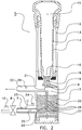
- FIG. 1 shows a diagrammatic side view of a milking system 1 according to the invention.
- the milking system 1 comprises a milking stall 2 with a robot 3 having a robot arm 4, and also a milking cup 5 having a measuring chamber 6 and a milk hose 7 in which there is a valve 8.
- Reference numeral 9 denotes a control unit and reference numeral 10 denotes a milk hose milk flow meter.
- Reference numeral 11 denotes a camera.
- reference numeral 30 denotes a dairy animal with an udder 31 and teats 32.
- the illustrated milking system is a milking robot system, which can attach the milking cups 5 fully automatically to the teats 32 of a dairy animal 30, such as a cow. Nevertheless, the invention can likewise be applied to a conventional milking system, where the milking cups are attached to the teats by hand.
- a teat detection system and milk pump parts which are not essentially important to the invention, such as a teat detection system and milk pump, are not shown.
- the milking cup 5 comprises a measuring chamber 6 which ends in a milk hose 7.
- the milk hose 7 can be closed using a valve 8 which is under the control of a control unit 9.
- the milk hose milk flow meter 10 is arranged on the milk hose 7 downstream of the valve 8 in order to measure the milk flow through the milk hose 7 during milking.
- This milk hose milk flow meter 10 is connected to the control unit 9, and also to the camera 11.
- Said camera 11 may serve not only as an aid for determining the position of the dairy animal 30 or the teats 32, but according to the invention in particular for determining a position of the milking cup 5 on the teat 32.
- the camera 11 may also serve to determine the height of the milking cup 5 and optionally of the valve 8. This height/these heights may be important in determining the milk flow on the basis of the passage opening of the valve 8. All of this will be explained in more detail with reference to figure 2 .
- Figure 2 shows a diagrammatic cross section of part of a milking system according to the present invention.
- similar parts are denoted by the same reference numerals.
- the milking cup 5 comprises a cup casing 12 and a lining 13, enclosing a pulsation space 14 between them.
- a teat space 15 which ends in a first milk outflow opening 16.
- a housing 17 for the measuring chamber 6 forms a rigid unit with the milking cup 5.
- the first milk outflow opening 16 opens (almost) directly into the milk inlet 18 which is connected to the measuring chamber 6 via a convex outflow 19.
- a vacuum line 22 is connected via a vacuum outlet 21.
- Reference numeral 23 denotes a measurement constricted section, on which is an additional sensor 24.
- the measurement constricted section 23 ends in the milk hose 7, via the second milk outflow opening 25.
- Reference numeral 26 denotes a level sensor which comprises a bottom electrode 27 and electrodes 28.
- reference numeral 29 denotes a vacuum sensor.
- the milking system comprises the illustrated rigid combination of a milking cup 5 and a housing 17 with the measuring chamber 6.
- the milk obtained from the teat in the teat space 15 flows to the measuring chamber 6 via the first milk outflow opening 16 and the milk inlet 18 directly via the outflow 19.
- the convex form of the outflow 19 and the resulting Coand effect means that the incoming milk will for the most part "adhere" to the wall of the housing 17, thus resulting in minimal foaming.
- a volume of single-phase milk 20 will in principle be formed at the bottom of the measuring chamber 6, with only air being present in the space above.
- This air although it is under a lower than atmospheric pressure, can be extracted via the vacuum outlet 21 and the vacuum line 22, which are connected to a vacuum system of the milking system which is not illustrated in detail here.
- the pressure will correspond to a normal milk vacuum, such as around 40 kPa.
- the housing 17 of the measuring chamber 6 and the cup casing 12 of the milking cup 5 form a rigid unit here.
- the milking cup and the housing may be separated by a short section of milk hose, so that, for example, it is more readily possible to ensure that the measuring chamber 6 will always hang substantially vertically during milking.
- the direct connection according to figure 2 offers the advantage of a more direct measurement of milk from the dairy animal.
- the obtained milk is (temporarily) collected in the measuring chamber 6, wherein the milk level will rise at the start of the milking.
- the level of the milk 20 in the measuring chamber 6 may be measured using a level sensor 26.
- this comprises a bottom electrode 27 and a series of electrodes 28 which extend over the height of the measuring chamber 6.
- the highest electrode 28 which, with the bottom electrode 27, exhibits a conductance which is greater than a threshold value indicates the level of the milk 20.
- the level sensor 26 is in operational connection with the control unit 9 (not shown here) and transmits a signal related to the measured milk height.
- the control unit 9 is also connected to the adjustable valve 8.
- the size of the passage opening of the valve 8 is determined by the control unit on the basis of the measured milk level. If the milk level in the measuring chamber 6 rises, at least to above a desired value, then the milk flow has evidently increased. In order to compensate for this by means of a milk outflow of an (approximately) equal size through the second milk outflow opening 25, the control unit will open the valve 8 further. By contrast, if the milk level falls, the control unit will close the valve further. This achieves a milk level in the measuring chamber 6 which is substantially as constant as possible.
- an advantage of this is that the measurement constricted section 23 connected to the measuring chamber 6 and the second milk outflow opening 25 can always be kept entirely submerged in milk but also continuously flowed through by fresh milk. A very reliable measurement of milk properties can thus be ensured.
- an additional sensor 24 is provided on the measurement constricted section 23.
- This additional sensor comprises, for example, an optical sensor, with a light source on one side of the measurement constricted section and a photodiode or the like on the opposite side of the measurement constricted section.
- the sensor 24 measures, for example, the transmittance for one or more colours, on the basis of which it is possible to reach a conclusion about the composition of the milk, such as fat content or, for example, milk containing blood.
- the sensor may be connected to the control unit 9, so that the control unit 9 can adjust one or more settings of the milking system 1 on the basis of the measured value from the additional sensor 24.
- the level sensor 26 may also be of a different type than the described type with the stacked electrodes, and may, for example, be a sensor which operates on the basis of optical transmittance of the measuring chamber 6.
- the measurement constricted section 23 is, for example, a narrowed part of the measuring chamber, with two (approximately) parallel walls which may be permeable to light or other radiation or fields.
- the level sensor 26 may sometimes measure an incorrect height of the milk 20 in the measuring chamber 6, for example if the level sensor 26 is located along a wall of the measuring chamber 6 and said wall is at an angle to the vertical, such as when attaching the milking cup 5 to a slanted teat.
- an inclination sensor such as the camera 11 from figure 1 . This can ascertain whether the milking cup with the housing 17 of the measuring chamber 6 is at an angle from the vertical and, if so, can ascertain this angle using image-processing software suitable for this purpose.
- the angle thus obtained can be transmitted to the control unit 9 which can use this to determine the correct height of the milk in the measuring chamber 6 according to simple geometric formulas.
- the milk flow can be determined in a very simple way on the basis of the height of the milk 20 in the measuring chamber 6 and the size of the passage opening of the valve 8. Where the conditions remain otherwise unchanged, in particular the pressure difference between the vacuum in the top part of the measuring chamber 6, in other words in the vacuum line 22, and the vacuum which prevails in order to discharge the milk through the milk hose 7, the milk flow can be simply calculated using hydrostatic equations.
- the control unit 9 from figure 1 together with the level sensor 26 and the valve 8, could serve as a milk flow meter.
- the liquid in the measuring chamber is not a milk/air mixture but substantially pure milk, which is an advantage achieved according to the invention.
- the vacuum sensor 29 may be provided, shown here in the vacuum line 22, but it may also be provided in, for example, the top part of the measuring chamber 6.
- the (milk) vacuum prevailing there, and also the prevailing milk transport vacuum which is determined by the milking system and can likewise be measured further along the milk hose, determine, together with the height of the milk column, the pressure difference over the passage opening of the valve 8, and thus the volume of the milk flow.
- the height of the milk column above the valve 8 is the height of the milk column above the valve 8. In the diagrammatic representation of figure 2 , this will be approximately constant, independently of the height at which the milking cup 5 is attached to a teat. However, as the valve 8 may also be located much further along the milk hose 7, for example a meter or more, it may be the case that the height of the milk column above the valve can vary greatly depending on the height of the teats of the dairy animal. In order to be able to take into account this height, it may be advantageous to use, for example, the camera 11 from figure 1 to determine the height of the milking cup and/or of the valve 8.
- the teat height is a property of the animal, which may also be stored and searched for in the control unit 9 of the milking system.
- the resulting position and form of the milk hose, and thus the height difference between the measuring chamber 6 and the valve 8, is substantially constant during each milking operation of said dairy animal.
- other measurement methods and sensors for determining and taking into account this height difference are not ruled out.
- an additional milk flow meter in particular a milk hose milk flow meter 10.
- this is located downstream of the valve 8, but could also be between the measuring chamber 6 and the valve 8.
- the milk flow is a single-phase system at the location of the milk hose milk flow meter 10
- a great variety of different meters may be used, in particular including very simple and reliable meters.
- An example of this is a milk flow meter on the basis of the magnetohydrodynamic principle, which has the advantage that it can measure the milk flow in an entirely contactless manner.
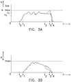
- Figures 3A and 3B show diagrammatic views with a milk level and a size of the passage opening of the valve 8 over time.
- Figure 3A shows how the milk level H can vary over time during the milking operation of a dairy animal.
- milk enters the measuring chamber and the valve is still closed. Accordingly, the milk level H will begin to rise.
- the height Hi being the minimum height, is reached.
- the control unit decides to already open the valve 8 by a small amount in order to prevent the milk level from rising too far.
- the milk level continues to rise until H r , the control height at which the control unit aims to keep the level constant.
- the control unit continues to adjust the position of the valve, and thus the size of the passage opening, in order to keep the milk level constant. In this case, it is best to ensure that the maximum passage opening of the valve is so large that it is in principle sufficient to keep the milk level below the permitted maximum (full measuring chamber).
- the control unit will start to reduce the passage opening A k in order to keep the milk level as constant as possible. This is illustrated in figures 3A and 3B by the fall in the value of A k .
- the milk level H then remains approximately constant also after time t 2 , until approximately time t 3 at which the milk flow has become too low to keep the milk level H at the desired level. After time t 3 , this milk level will therefore fall rapidly until the end of the milking operation at time t 4 .
- FIG. 3B shows that the valve is already being closed in an accelerated manner at time t 2 , as a result of which the milk level H will rise to the permitted maximum H max . It is thus possible to enable a more efficient milking of the teat.
Landscapes
- Life Sciences & Earth Sciences (AREA)
- Animal Husbandry (AREA)
- Environmental Sciences (AREA)
- Physics & Mathematics (AREA)
- Fluid Mechanics (AREA)
- General Physics & Mathematics (AREA)
- Measuring Volume Flow (AREA)
Claims (15)
- Melksystem (1) zum Melken eines Milchtiers (30), und umfassend- mindestens einen Melkbecher (5) mit einer ersten Milchaustrittsöffnung (16),- eine Messkammer (6) mit einem in Strömungsverbindung mit der ersten Milchaustrittsöffnung stehenden Milcheinlass (18), mit einer zweiten Milchaustritts(25)-Öffnung zu einem Milchschlauch (7) und mit einer Unterdruckverbindung (21),- einen Füllstandsensor (26) zum Messen eines Milchfüllstands in der Messkammer,- ein steuerbares Ventil (8) mit einer verstellbaren Durchgangsöffnung, die in oder stromabwärts der zweiten Milchaustrittsöffnung vorgesehen ist, und- eine Steuereinheit (9), die mit dem Füllstandsensor und dem Ventil wirkverbunden ist, und die ausgestaltet ist, die Durchgangsöffnung des Ventils auf der Basis des gemessenen Milchfüllstands zu verstellen, dadurch gekennzeichnet, dass die Steuereinheit (9) ferner ausgestaltet ist, die Durchgangsöffnung während zumindest eines Teils eines Melkvorgangs zwischen einer kleinsten Öffnungsposition und einer größten Öffnungsposition zu verstellen.
- Melksystem nach Anspruch 1, wobei die Messkammer direkt und starr mit dem Melkbecher verbunden ist, und insbesondere wobei der Melkbecher und die Messkammer eine starre Einheit bilden.
- Melksystem nach einem der vorhergehenden Ansprüche, wobei die Steuereinheit ausgestaltet ist, die Durchgangsöffnung zumindest während einer Hauptmelkphase des Melkvorgangs fortlaufend zu verstellen.
- Melksystem nach einem der vorhergehenden Ansprüche, wobei die Steuereinheit ausgestaltet ist, die Durchgangsöffnung im Fall eines steigenden Milchfüllstands zu vergrößern und die Durchgangsöffnung im Fall eines sinkenden Milchfüllstands zu verkleinern.
- Melksystem nach Anspruch 4, wobei die Steuereinheit ausgestaltet ist, die Durchgangsöffnung derart zu verstellen, dass das Ziel ein gleichbleibender Milchfüllstand ist.
- Melksystem nach einem der vorhergehenden Ansprüche, wobei sich der Füllstandsensor während des Melkens im Wesentlichen vertikal über eine innere Höhe der Messkammer erstreckt, und insbesondere eine Reihe von voneinander getrennten Elektroden (27, 28) umfasst, die über eine Sensorsteuereinheit elektrisch verbindbar sind.
- Melksystem nach einem der vorhergehenden Ansprüche, umfassend einen Neigungssensor (11) zum Bestimmen einer Neigung des Melkbechers, wobei die Steuereinheit mit dem Neigungssensor wirkverbunden ist und ausgestaltet ist, den gemessenen Milchfüllstand auf der Basis der bestimmten Neigung zu korrigieren.
- Melksystem nach einem der vorhergehenden Ansprüche, wobei das Ventil in der Messkammer, insbesondere in der zweiten Milchaustrittsöffnung vorgesehen ist.
- Melksystem nach einem der vorhergehenden Ansprüche, umfassend einen Milchdurchflussmesser (9, 26, 8), der ausgestaltet ist, den Milchdurchfluss durch die zweite Milchaustrittsöffnung auf der Basis der Durchgangsöffnung des Ventils zu bestimmen.
- Melksystem nach Anspruch 9, umfassend eine Druckmessvorrichtung (29), die ausgestaltet ist, eine Druckdifferenz über das Ventil und/oder die Durchgangsöffnung zu messen, insbesondere umfassend einen ersten Drucksensor, der ausgestaltet ist, einen Druck in der Messkammer zu messen, und einen zweiten Drucksensor zum Messen eines Drucks in dem Milchschlauch, insbesondere am Ventil vorbei.
- Melksystem nach Anspruch 9 oder 10, umfassend eine Höhenbestimmungsvorrichtung (11), die ausgestaltet ist, eine Melkhöhe, in der sich die Messkammer während eines Melkens des Milchtiers befindet, insbesondere auch eine Ventilhöhe, in der sich das Ventil während des Melkens befindet, zu bestimmen, und wobei der Milchdurchflussmesser mit der Höhenbestimmungsvorrichtung wirkverbunden ist und ausgestaltet ist, den Milchdurchfluss auf der Basis der bestimmten Melkhöhe, und insbesondere auch der Ventilhöhe zu bestimmen.
- Melksystem nach einem der vorhergehenden Ansprüche, umfassend einen Milchschlauchmilchdurchflussmesser (10) in oder um den Milchschlauch zum Messen des Milchdurchflusses, insbesondere ein kontaktlos messender Milchschlauchmilchdurchflussmesser, genauer gesagt ein elektrisch oder elektromagnetisch betriebener Milchschlauchmilchdurchflussmesser, vorteilhafterweise ein magnetohydrodynamischer Milchschlauchmilchdurchflussmesser.
- Melksystem nach einem der vorhergehenden Ansprüche, wobei die Messkammer einen, vorzugsweise abgerundeten oder runden, Querschnitt (19) aufweist, der sich weg von dem Milcheinlass vergrößert.
- Melksystem nach einem der vorhergehenden Ansprüche, umfassend einen zusätzlichen Sensor (24) zum Messen einer milchbezogenen Eigenschaft, insbesondere einen Sensor zum Messen einer Milcheigenschaft.
- Melksystem nach einem der vorhergehenden Ansprüche, abhängig von Anspruch 9 oder 12, wobei die Steuereinheit ausgestaltet ist, das Ventil derart zu steuern, dass sich der Milchfüllstand erhöht, wenn der bestimmte oder gemessene Milchdurchfluss unter einen Schwellenwert fällt.
Applications Claiming Priority (2)
| Application Number | Priority Date | Filing Date | Title |
|---|---|---|---|
| NL2017992A NL2017992B1 (nl) | 2016-12-14 | 2016-12-14 | Melksysteem |
| PCT/NL2017/050781 WO2018111095A1 (en) | 2016-12-14 | 2017-11-27 | Milking system |
Publications (2)
| Publication Number | Publication Date |
|---|---|
| EP3554224A1 EP3554224A1 (de) | 2019-10-23 |
| EP3554224B1 true EP3554224B1 (de) | 2021-02-24 |
Family
ID=57629670
Family Applications (1)
| Application Number | Title | Priority Date | Filing Date |
|---|---|---|---|
| EP17817920.6A Active EP3554224B1 (de) | 2016-12-14 | 2017-11-27 | Melksystem |
Country Status (5)
| Country | Link |
|---|---|
| US (1) | US11452277B2 (de) |
| EP (1) | EP3554224B1 (de) |
| CA (1) | CA3046453A1 (de) |
| NL (1) | NL2017992B1 (de) |
| WO (1) | WO2018111095A1 (de) |
Families Citing this family (2)
| Publication number | Priority date | Publication date | Assignee | Title |
|---|---|---|---|---|
| EP3533479A1 (de) * | 2018-02-28 | 2019-09-04 | Koninklijke Philips N.V. | Brustpumpenanordnung |
| NL2030111B1 (nl) | 2021-12-13 | 2023-06-27 | Lely Patent Nv | Melksysteem |
Family Cites Families (26)
| Publication number | Priority date | Publication date | Assignee | Title |
|---|---|---|---|---|
| US3600944A (en) * | 1968-11-08 | 1971-08-24 | William David John Hutchings | Milk meters |
| US3919975A (en) * | 1974-08-05 | 1975-11-18 | Lloyd P Duncan | Milker unit |
| US4170198A (en) * | 1977-09-21 | 1979-10-09 | Gordon Philip D | Semi-automatic milk flow sensor |
| US4112758A (en) * | 1977-10-21 | 1978-09-12 | Dairy Systems, Inc. | Milk monitoring method and apparatus |
| DE2810376B2 (de) * | 1978-03-10 | 1980-04-03 | D E C Gmbh, 4660 Gelsenkirchen-Buer | MilchmengenmeBgerät |
| US4188910A (en) * | 1978-04-03 | 1980-02-19 | Hocker Van G | Combined milk flow sensing and vacuum shut-off device |
| SE7909054L (sv) * | 1978-11-03 | 1980-05-04 | Foss Electric As N | Sett och apparat for flodesmetning |
| IL58203A (en) * | 1979-09-07 | 1982-09-30 | Mahanaim Diuk Hydraulica | Milk flow measurement apparatus |
| US4771007A (en) * | 1982-03-18 | 1988-09-13 | Wescor, Inc. | Electrical conductivity device for detecting mastitis in dairy cows |
| GB8323688D0 (en) * | 1983-09-03 | 1983-10-05 | Flow Measurement Control Ltd | Air elimination system |
| DE3609275A1 (de) * | 1986-03-19 | 1987-09-24 | Werner Ludwig Schmidt | Verfahren zum maschinellen milchentzug |
| DE3737607A1 (de) * | 1987-11-05 | 1989-05-24 | Hoefelmayr Bio Melktech | Verfahren und vorrichtung zur durchfuehrung von messungen an einer schaeumenden fluessigkeit |
| NL193553C (nl) * | 1989-02-27 | 2003-01-10 | Lely Entpr Ag | Melkinstallatie. |
| US5568788A (en) * | 1990-02-27 | 1996-10-29 | C. Van Der Lely N.V. | Implement for and a method of milking animals automatically |
| US5083459A (en) * | 1990-05-14 | 1992-01-28 | Lind Leroy R | Flow meter |
| US5218924A (en) * | 1992-03-19 | 1993-06-15 | Dec International, Inc. | Milking system with variable pressure source |
| DE69525934T2 (de) * | 1994-12-09 | 2002-10-31 | Maasland N.V., Maasland | Vorrichtung zum melken von tieren |
| US5720236A (en) * | 1996-01-16 | 1998-02-24 | Dec International, Inc. | Milk meter |
| US5715856A (en) * | 1996-03-22 | 1998-02-10 | Martin; Tommy | Liquid flow control apparatus |
| US6142098A (en) * | 1998-05-06 | 2000-11-07 | Maasland N.V. | Teat cup and a milking robot comprising same |
| US6604053B2 (en) * | 2001-02-13 | 2003-08-05 | Global Tech Systems, Inc. | Method for measuring flow rate of a continuous fluid flow |
| US6741942B2 (en) * | 2002-01-07 | 2004-05-25 | S.A.E. Afikim | Free-flow fluid measurement meter |
| EP1443324A1 (de) | 2003-01-31 | 2004-08-04 | DeLaval Holding AB | Milchmengenmessvorrichtung und Verfahren zum Melken eines Tieres |
| ATE516702T1 (de) * | 2007-05-22 | 2011-08-15 | Bartec Benke Gmbh | Verfahren und vorrichtung zur mengenbestimmung bei der übergabe einer flüssigkeit |
| DE102008057819B4 (de) * | 2008-11-18 | 2016-05-19 | Lactocorder Ag | Vorrichtung und Verfahren zum Messen einer von einem Tier bei einem Melkvorgang abgegebenen Milchmenge |
| WO2010098124A1 (ja) * | 2009-02-26 | 2010-09-02 | オリオン機械株式会社 | 乳量計及び搾乳装置 |
-
2016
- 2016-12-14 NL NL2017992A patent/NL2017992B1/nl not_active IP Right Cessation
-
2017
- 2017-11-27 CA CA3046453A patent/CA3046453A1/en active Pending
- 2017-11-27 WO PCT/NL2017/050781 patent/WO2018111095A1/en not_active Ceased
- 2017-11-27 EP EP17817920.6A patent/EP3554224B1/de active Active
- 2017-11-27 US US16/467,390 patent/US11452277B2/en active Active
Non-Patent Citations (1)
| Title |
|---|
| None * |
Also Published As
| Publication number | Publication date |
|---|---|
| CA3046453A1 (en) | 2018-06-21 |
| US20200084994A1 (en) | 2020-03-19 |
| US11452277B2 (en) | 2022-09-27 |
| WO2018111095A1 (en) | 2018-06-21 |
| NL2017992B1 (nl) | 2018-06-26 |
| EP3554224A1 (de) | 2019-10-23 |
Similar Documents
| Publication | Publication Date | Title |
|---|---|---|
| AU2009317574B2 (en) | Device and method for measurement of a milk volume yielded from an animal during a milking process | |
| JP5123211B2 (ja) | 搾乳システムおよび真空調整方法 | |
| EP2968713B1 (de) | Kleinvolumige sammlung für ein milchpumpensystem | |
| US6604053B2 (en) | Method for measuring flow rate of a continuous fluid flow | |
| DK158162B (da) | Apparat til maaling af den i en malkning udmalkede totale maelkemaengde fra en ko | |
| EP3554224B1 (de) | Melksystem | |
| EP1155610B1 (de) | Mengenmesser und damit ausgerüstete Vorrichtung zum Melken von Tieren | |
| US5896827A (en) | Milking system having a substantially stable continuous vacuum level | |
| US20240156043A1 (en) | Milk sampling device, and milking system therewith | |
| EP4447651B1 (de) | Melksystem | |
| WO1999059399A1 (en) | A method and a device for milking an animal | |
| US11484003B2 (en) | Milking system | |
| SE527216C2 (sv) | Metod för att styra mjölkning av ett djur med hjälp av vakuumet i spenkoppskragen och anordning därför | |
| RU2684214C1 (ru) | Потокомер для доильных аппаратов | |
| CA3046053C (en) | Milking system | |
| SE528603C2 (sv) | Förfarande, datorprogramprodukt och anordning för styrning av mjölkningen utförd av en mjölkningsmaskin | |
| RU2318377C1 (ru) | Доильный аппарат |
Legal Events
| Date | Code | Title | Description |
|---|---|---|---|
| STAA | Information on the status of an ep patent application or granted ep patent |
Free format text: STATUS: UNKNOWN |
|
| STAA | Information on the status of an ep patent application or granted ep patent |
Free format text: STATUS: THE INTERNATIONAL PUBLICATION HAS BEEN MADE |
|
| PUAI | Public reference made under article 153(3) epc to a published international application that has entered the european phase |
Free format text: ORIGINAL CODE: 0009012 |
|
| STAA | Information on the status of an ep patent application or granted ep patent |
Free format text: STATUS: REQUEST FOR EXAMINATION WAS MADE |
|
| 17P | Request for examination filed |
Effective date: 20190715 |
|
| AK | Designated contracting states |
Kind code of ref document: A1 Designated state(s): AL AT BE BG CH CY CZ DE DK EE ES FI FR GB GR HR HU IE IS IT LI LT LU LV MC MK MT NL NO PL PT RO RS SE SI SK SM TR |
|
| AX | Request for extension of the european patent |
Extension state: BA ME |
|
| DAV | Request for validation of the european patent (deleted) | ||
| DAX | Request for extension of the european patent (deleted) | ||
| GRAP | Despatch of communication of intention to grant a patent |
Free format text: ORIGINAL CODE: EPIDOSNIGR1 |
|
| STAA | Information on the status of an ep patent application or granted ep patent |
Free format text: STATUS: GRANT OF PATENT IS INTENDED |
|
| INTG | Intention to grant announced |
Effective date: 20200914 |
|
| GRAS | Grant fee paid |
Free format text: ORIGINAL CODE: EPIDOSNIGR3 |
|
| GRAA | (expected) grant |
Free format text: ORIGINAL CODE: 0009210 |
|
| STAA | Information on the status of an ep patent application or granted ep patent |
Free format text: STATUS: THE PATENT HAS BEEN GRANTED |
|
| AK | Designated contracting states |
Kind code of ref document: B1 Designated state(s): AL AT BE BG CH CY CZ DE DK EE ES FI FR GB GR HR HU IE IS IT LI LT LU LV MC MK MT NL NO PL PT RO RS SE SI SK SM TR |
|
| REG | Reference to a national code |
Ref country code: CH Ref legal event code: EP |
|
| REG | Reference to a national code |
Ref country code: AT Ref legal event code: REF Ref document number: 1363316 Country of ref document: AT Kind code of ref document: T Effective date: 20210315 |
|
| REG | Reference to a national code |
Ref country code: IE Ref legal event code: FG4D |
|
| REG | Reference to a national code |
Ref country code: DE Ref legal event code: R096 Ref document number: 602017033458 Country of ref document: DE |
|
| REG | Reference to a national code |
Ref country code: NL Ref legal event code: FP |
|
| REG | Reference to a national code |
Ref country code: SE Ref legal event code: TRGR |
|
| REG | Reference to a national code |
Ref country code: LT Ref legal event code: MG9D |
|
| PG25 | Lapsed in a contracting state [announced via postgrant information from national office to epo] |
Ref country code: NO Free format text: LAPSE BECAUSE OF FAILURE TO SUBMIT A TRANSLATION OF THE DESCRIPTION OR TO PAY THE FEE WITHIN THE PRESCRIBED TIME-LIMIT Effective date: 20210524 Ref country code: PT Free format text: LAPSE BECAUSE OF FAILURE TO SUBMIT A TRANSLATION OF THE DESCRIPTION OR TO PAY THE FEE WITHIN THE PRESCRIBED TIME-LIMIT Effective date: 20210624 Ref country code: HR Free format text: LAPSE BECAUSE OF FAILURE TO SUBMIT A TRANSLATION OF THE DESCRIPTION OR TO PAY THE FEE WITHIN THE PRESCRIBED TIME-LIMIT Effective date: 20210224 Ref country code: GR Free format text: LAPSE BECAUSE OF FAILURE TO SUBMIT A TRANSLATION OF THE DESCRIPTION OR TO PAY THE FEE WITHIN THE PRESCRIBED TIME-LIMIT Effective date: 20210525 Ref country code: FI Free format text: LAPSE BECAUSE OF FAILURE TO SUBMIT A TRANSLATION OF THE DESCRIPTION OR TO PAY THE FEE WITHIN THE PRESCRIBED TIME-LIMIT Effective date: 20210224 Ref country code: LT Free format text: LAPSE BECAUSE OF FAILURE TO SUBMIT A TRANSLATION OF THE DESCRIPTION OR TO PAY THE FEE WITHIN THE PRESCRIBED TIME-LIMIT Effective date: 20210224 Ref country code: BG Free format text: LAPSE BECAUSE OF FAILURE TO SUBMIT A TRANSLATION OF THE DESCRIPTION OR TO PAY THE FEE WITHIN THE PRESCRIBED TIME-LIMIT Effective date: 20210524 |
|
| REG | Reference to a national code |
Ref country code: AT Ref legal event code: MK05 Ref document number: 1363316 Country of ref document: AT Kind code of ref document: T Effective date: 20210224 |
|
| PG25 | Lapsed in a contracting state [announced via postgrant information from national office to epo] |
Ref country code: LV Free format text: LAPSE BECAUSE OF FAILURE TO SUBMIT A TRANSLATION OF THE DESCRIPTION OR TO PAY THE FEE WITHIN THE PRESCRIBED TIME-LIMIT Effective date: 20210224 Ref country code: RS Free format text: LAPSE BECAUSE OF FAILURE TO SUBMIT A TRANSLATION OF THE DESCRIPTION OR TO PAY THE FEE WITHIN THE PRESCRIBED TIME-LIMIT Effective date: 20210224 Ref country code: PL Free format text: LAPSE BECAUSE OF FAILURE TO SUBMIT A TRANSLATION OF THE DESCRIPTION OR TO PAY THE FEE WITHIN THE PRESCRIBED TIME-LIMIT Effective date: 20210224 |
|
| PG25 | Lapsed in a contracting state [announced via postgrant information from national office to epo] |
Ref country code: IS Free format text: LAPSE BECAUSE OF FAILURE TO SUBMIT A TRANSLATION OF THE DESCRIPTION OR TO PAY THE FEE WITHIN THE PRESCRIBED TIME-LIMIT Effective date: 20210624 |
|
| PG25 | Lapsed in a contracting state [announced via postgrant information from national office to epo] |
Ref country code: CZ Free format text: LAPSE BECAUSE OF FAILURE TO SUBMIT A TRANSLATION OF THE DESCRIPTION OR TO PAY THE FEE WITHIN THE PRESCRIBED TIME-LIMIT Effective date: 20210224 Ref country code: EE Free format text: LAPSE BECAUSE OF FAILURE TO SUBMIT A TRANSLATION OF THE DESCRIPTION OR TO PAY THE FEE WITHIN THE PRESCRIBED TIME-LIMIT Effective date: 20210224 Ref country code: AT Free format text: LAPSE BECAUSE OF FAILURE TO SUBMIT A TRANSLATION OF THE DESCRIPTION OR TO PAY THE FEE WITHIN THE PRESCRIBED TIME-LIMIT Effective date: 20210224 Ref country code: SM Free format text: LAPSE BECAUSE OF FAILURE TO SUBMIT A TRANSLATION OF THE DESCRIPTION OR TO PAY THE FEE WITHIN THE PRESCRIBED TIME-LIMIT Effective date: 20210224 |
|
| REG | Reference to a national code |
Ref country code: DE Ref legal event code: R097 Ref document number: 602017033458 Country of ref document: DE |
|
| PG25 | Lapsed in a contracting state [announced via postgrant information from national office to epo] |
Ref country code: DK Free format text: LAPSE BECAUSE OF FAILURE TO SUBMIT A TRANSLATION OF THE DESCRIPTION OR TO PAY THE FEE WITHIN THE PRESCRIBED TIME-LIMIT Effective date: 20210224 Ref country code: SK Free format text: LAPSE BECAUSE OF FAILURE TO SUBMIT A TRANSLATION OF THE DESCRIPTION OR TO PAY THE FEE WITHIN THE PRESCRIBED TIME-LIMIT Effective date: 20210224 Ref country code: RO Free format text: LAPSE BECAUSE OF FAILURE TO SUBMIT A TRANSLATION OF THE DESCRIPTION OR TO PAY THE FEE WITHIN THE PRESCRIBED TIME-LIMIT Effective date: 20210224 |
|
| PLBE | No opposition filed within time limit |
Free format text: ORIGINAL CODE: 0009261 |
|
| STAA | Information on the status of an ep patent application or granted ep patent |
Free format text: STATUS: NO OPPOSITION FILED WITHIN TIME LIMIT |
|
| PG25 | Lapsed in a contracting state [announced via postgrant information from national office to epo] |
Ref country code: AL Free format text: LAPSE BECAUSE OF FAILURE TO SUBMIT A TRANSLATION OF THE DESCRIPTION OR TO PAY THE FEE WITHIN THE PRESCRIBED TIME-LIMIT Effective date: 20210224 Ref country code: ES Free format text: LAPSE BECAUSE OF FAILURE TO SUBMIT A TRANSLATION OF THE DESCRIPTION OR TO PAY THE FEE WITHIN THE PRESCRIBED TIME-LIMIT Effective date: 20210224 |
|
| 26N | No opposition filed |
Effective date: 20211125 |
|
| PG25 | Lapsed in a contracting state [announced via postgrant information from national office to epo] |
Ref country code: SI Free format text: LAPSE BECAUSE OF FAILURE TO SUBMIT A TRANSLATION OF THE DESCRIPTION OR TO PAY THE FEE WITHIN THE PRESCRIBED TIME-LIMIT Effective date: 20210224 |
|
| PG25 | Lapsed in a contracting state [announced via postgrant information from national office to epo] |
Ref country code: IT Free format text: LAPSE BECAUSE OF FAILURE TO SUBMIT A TRANSLATION OF THE DESCRIPTION OR TO PAY THE FEE WITHIN THE PRESCRIBED TIME-LIMIT Effective date: 20210224 |
|
| PG25 | Lapsed in a contracting state [announced via postgrant information from national office to epo] |
Ref country code: IS Free format text: LAPSE BECAUSE OF FAILURE TO SUBMIT A TRANSLATION OF THE DESCRIPTION OR TO PAY THE FEE WITHIN THE PRESCRIBED TIME-LIMIT Effective date: 20210624 |
|
| PG25 | Lapsed in a contracting state [announced via postgrant information from national office to epo] |
Ref country code: MC Free format text: LAPSE BECAUSE OF FAILURE TO SUBMIT A TRANSLATION OF THE DESCRIPTION OR TO PAY THE FEE WITHIN THE PRESCRIBED TIME-LIMIT Effective date: 20210224 |
|
| REG | Reference to a national code |
Ref country code: CH Ref legal event code: PL |
|
| PG25 | Lapsed in a contracting state [announced via postgrant information from national office to epo] |
Ref country code: LU Free format text: LAPSE BECAUSE OF NON-PAYMENT OF DUE FEES Effective date: 20211127 Ref country code: BE Free format text: LAPSE BECAUSE OF NON-PAYMENT OF DUE FEES Effective date: 20211130 |
|
| REG | Reference to a national code |
Ref country code: BE Ref legal event code: MM Effective date: 20211130 |
|
| PG25 | Lapsed in a contracting state [announced via postgrant information from national office to epo] |
Ref country code: IE Free format text: LAPSE BECAUSE OF NON-PAYMENT OF DUE FEES Effective date: 20211127 |
|
| P01 | Opt-out of the competence of the unified patent court (upc) registered |
Effective date: 20230425 |
|
| PG25 | Lapsed in a contracting state [announced via postgrant information from national office to epo] |
Ref country code: CY Free format text: LAPSE BECAUSE OF FAILURE TO SUBMIT A TRANSLATION OF THE DESCRIPTION OR TO PAY THE FEE WITHIN THE PRESCRIBED TIME-LIMIT Effective date: 20210224 |
|
| PG25 | Lapsed in a contracting state [announced via postgrant information from national office to epo] |
Ref country code: LI Free format text: LAPSE BECAUSE OF NON-PAYMENT OF DUE FEES Effective date: 20220701 Ref country code: HU Free format text: LAPSE BECAUSE OF FAILURE TO SUBMIT A TRANSLATION OF THE DESCRIPTION OR TO PAY THE FEE WITHIN THE PRESCRIBED TIME-LIMIT; INVALID AB INITIO Effective date: 20171127 Ref country code: CH Free format text: LAPSE BECAUSE OF NON-PAYMENT OF DUE FEES Effective date: 20220701 |
|
| REG | Reference to a national code |
Ref country code: DE Ref legal event code: R084 Ref document number: 602017033458 Country of ref document: DE |
|
| REG | Reference to a national code |
Ref country code: GB Ref legal event code: 746 Effective date: 20231027 |
|
| PG25 | Lapsed in a contracting state [announced via postgrant information from national office to epo] |
Ref country code: MK Free format text: LAPSE BECAUSE OF FAILURE TO SUBMIT A TRANSLATION OF THE DESCRIPTION OR TO PAY THE FEE WITHIN THE PRESCRIBED TIME-LIMIT Effective date: 20210224 |
|
| PG25 | Lapsed in a contracting state [announced via postgrant information from national office to epo] |
Ref country code: MT Free format text: LAPSE BECAUSE OF FAILURE TO SUBMIT A TRANSLATION OF THE DESCRIPTION OR TO PAY THE FEE WITHIN THE PRESCRIBED TIME-LIMIT Effective date: 20210224 |
|
| PG25 | Lapsed in a contracting state [announced via postgrant information from national office to epo] |
Ref country code: TR Free format text: LAPSE BECAUSE OF FAILURE TO SUBMIT A TRANSLATION OF THE DESCRIPTION OR TO PAY THE FEE WITHIN THE PRESCRIBED TIME-LIMIT Effective date: 20210224 |
|
| PGFP | Annual fee paid to national office [announced via postgrant information from national office to epo] |
Ref country code: NL Payment date: 20251126 Year of fee payment: 9 |
|
| PGFP | Annual fee paid to national office [announced via postgrant information from national office to epo] |
Ref country code: DE Payment date: 20251128 Year of fee payment: 9 |
|
| PGFP | Annual fee paid to national office [announced via postgrant information from national office to epo] |
Ref country code: GB Payment date: 20251127 Year of fee payment: 9 |
|
| PGFP | Annual fee paid to national office [announced via postgrant information from national office to epo] |
Ref country code: FR Payment date: 20251125 Year of fee payment: 9 |
|
| PGFP | Annual fee paid to national office [announced via postgrant information from national office to epo] |
Ref country code: SE Payment date: 20251127 Year of fee payment: 9 |