EP3554427B1 - Bandscheibenprothese und verfahren zur herstellung einer bandscheibenprothese - Google Patents
Bandscheibenprothese und verfahren zur herstellung einer bandscheibenprothese Download PDFInfo
- Publication number
- EP3554427B1 EP3554427B1 EP17818079.0A EP17818079A EP3554427B1 EP 3554427 B1 EP3554427 B1 EP 3554427B1 EP 17818079 A EP17818079 A EP 17818079A EP 3554427 B1 EP3554427 B1 EP 3554427B1
- Authority
- EP
- European Patent Office
- Prior art keywords
- plate
- core
- caudal
- cranial
- cavity
- Prior art date
- Legal status (The legal status is an assumption and is not a legal conclusion. Google has not performed a legal analysis and makes no representation as to the accuracy of the status listed.)
- Active
Links
Images
Classifications
-
- A—HUMAN NECESSITIES
- A61—MEDICAL OR VETERINARY SCIENCE; HYGIENE
- A61F—FILTERS IMPLANTABLE INTO BLOOD VESSELS; PROSTHESES; DEVICES PROVIDING PATENCY TO, OR PREVENTING COLLAPSING OF, TUBULAR STRUCTURES OF THE BODY, e.g. STENTS; ORTHOPAEDIC, NURSING OR CONTRACEPTIVE DEVICES; FOMENTATION; TREATMENT OR PROTECTION OF EYES OR EARS; BANDAGES, DRESSINGS OR ABSORBENT PADS; FIRST-AID KITS
- A61F2/00—Filters implantable into blood vessels; Prostheses, i.e. artificial substitutes or replacements for parts of the body; Appliances for connecting them with the body; Devices providing patency to, or preventing collapsing of, tubular structures of the body, e.g. stents
- A61F2/02—Prostheses implantable into the body
- A61F2/30—Joints
- A61F2/44—Joints for the spine, e.g. vertebrae, spinal discs
- A61F2/442—Intervertebral or spinal discs, e.g. resilient
-
- A—HUMAN NECESSITIES
- A61—MEDICAL OR VETERINARY SCIENCE; HYGIENE
- A61F—FILTERS IMPLANTABLE INTO BLOOD VESSELS; PROSTHESES; DEVICES PROVIDING PATENCY TO, OR PREVENTING COLLAPSING OF, TUBULAR STRUCTURES OF THE BODY, e.g. STENTS; ORTHOPAEDIC, NURSING OR CONTRACEPTIVE DEVICES; FOMENTATION; TREATMENT OR PROTECTION OF EYES OR EARS; BANDAGES, DRESSINGS OR ABSORBENT PADS; FIRST-AID KITS
- A61F2/00—Filters implantable into blood vessels; Prostheses, i.e. artificial substitutes or replacements for parts of the body; Appliances for connecting them with the body; Devices providing patency to, or preventing collapsing of, tubular structures of the body, e.g. stents
- A61F2/02—Prostheses implantable into the body
- A61F2/30—Joints
- A61F2002/30001—Additional features of subject-matter classified in A61F2/28, A61F2/30 and subgroups thereof
- A61F2002/30003—Material related properties of the prosthesis or of a coating on the prosthesis
- A61F2002/3006—Properties of materials and coating materials
- A61F2002/30069—Properties of materials and coating materials elastomeric
-
- A—HUMAN NECESSITIES
- A61—MEDICAL OR VETERINARY SCIENCE; HYGIENE
- A61F—FILTERS IMPLANTABLE INTO BLOOD VESSELS; PROSTHESES; DEVICES PROVIDING PATENCY TO, OR PREVENTING COLLAPSING OF, TUBULAR STRUCTURES OF THE BODY, e.g. STENTS; ORTHOPAEDIC, NURSING OR CONTRACEPTIVE DEVICES; FOMENTATION; TREATMENT OR PROTECTION OF EYES OR EARS; BANDAGES, DRESSINGS OR ABSORBENT PADS; FIRST-AID KITS
- A61F2/00—Filters implantable into blood vessels; Prostheses, i.e. artificial substitutes or replacements for parts of the body; Appliances for connecting them with the body; Devices providing patency to, or preventing collapsing of, tubular structures of the body, e.g. stents
- A61F2/02—Prostheses implantable into the body
- A61F2/30—Joints
- A61F2002/30001—Additional features of subject-matter classified in A61F2/28, A61F2/30 and subgroups thereof
- A61F2002/30108—Shapes
- A61F2002/30199—Three-dimensional shapes
-
- A—HUMAN NECESSITIES
- A61—MEDICAL OR VETERINARY SCIENCE; HYGIENE
- A61F—FILTERS IMPLANTABLE INTO BLOOD VESSELS; PROSTHESES; DEVICES PROVIDING PATENCY TO, OR PREVENTING COLLAPSING OF, TUBULAR STRUCTURES OF THE BODY, e.g. STENTS; ORTHOPAEDIC, NURSING OR CONTRACEPTIVE DEVICES; FOMENTATION; TREATMENT OR PROTECTION OF EYES OR EARS; BANDAGES, DRESSINGS OR ABSORBENT PADS; FIRST-AID KITS
- A61F2/00—Filters implantable into blood vessels; Prostheses, i.e. artificial substitutes or replacements for parts of the body; Appliances for connecting them with the body; Devices providing patency to, or preventing collapsing of, tubular structures of the body, e.g. stents
- A61F2/02—Prostheses implantable into the body
- A61F2/30—Joints
- A61F2002/30001—Additional features of subject-matter classified in A61F2/28, A61F2/30 and subgroups thereof
- A61F2002/30108—Shapes
- A61F2002/30199—Three-dimensional shapes
- A61F2002/30242—Three-dimensional shapes spherical
- A61F2002/30245—Partial spheres
-
- A—HUMAN NECESSITIES
- A61—MEDICAL OR VETERINARY SCIENCE; HYGIENE
- A61F—FILTERS IMPLANTABLE INTO BLOOD VESSELS; PROSTHESES; DEVICES PROVIDING PATENCY TO, OR PREVENTING COLLAPSING OF, TUBULAR STRUCTURES OF THE BODY, e.g. STENTS; ORTHOPAEDIC, NURSING OR CONTRACEPTIVE DEVICES; FOMENTATION; TREATMENT OR PROTECTION OF EYES OR EARS; BANDAGES, DRESSINGS OR ABSORBENT PADS; FIRST-AID KITS
- A61F2/00—Filters implantable into blood vessels; Prostheses, i.e. artificial substitutes or replacements for parts of the body; Appliances for connecting them with the body; Devices providing patency to, or preventing collapsing of, tubular structures of the body, e.g. stents
- A61F2/02—Prostheses implantable into the body
- A61F2/30—Joints
- A61F2002/30001—Additional features of subject-matter classified in A61F2/28, A61F2/30 and subgroups thereof
- A61F2002/30316—The prosthesis having different structural features at different locations within the same prosthesis; Connections between prosthetic parts; Special structural features of bone or joint prostheses not otherwise provided for
- A61F2002/30329—Connections or couplings between prosthetic parts, e.g. between modular parts; Connecting elements
- A61F2002/30331—Connections or couplings between prosthetic parts, e.g. between modular parts; Connecting elements made by longitudinally pushing a protrusion into a complementarily-shaped recess, e.g. held by friction fit
-
- A—HUMAN NECESSITIES
- A61—MEDICAL OR VETERINARY SCIENCE; HYGIENE
- A61F—FILTERS IMPLANTABLE INTO BLOOD VESSELS; PROSTHESES; DEVICES PROVIDING PATENCY TO, OR PREVENTING COLLAPSING OF, TUBULAR STRUCTURES OF THE BODY, e.g. STENTS; ORTHOPAEDIC, NURSING OR CONTRACEPTIVE DEVICES; FOMENTATION; TREATMENT OR PROTECTION OF EYES OR EARS; BANDAGES, DRESSINGS OR ABSORBENT PADS; FIRST-AID KITS
- A61F2/00—Filters implantable into blood vessels; Prostheses, i.e. artificial substitutes or replacements for parts of the body; Appliances for connecting them with the body; Devices providing patency to, or preventing collapsing of, tubular structures of the body, e.g. stents
- A61F2/02—Prostheses implantable into the body
- A61F2/30—Joints
- A61F2002/30001—Additional features of subject-matter classified in A61F2/28, A61F2/30 and subgroups thereof
- A61F2002/30316—The prosthesis having different structural features at different locations within the same prosthesis; Connections between prosthetic parts; Special structural features of bone or joint prostheses not otherwise provided for
- A61F2002/30329—Connections or couplings between prosthetic parts, e.g. between modular parts; Connecting elements
- A61F2002/30331—Connections or couplings between prosthetic parts, e.g. between modular parts; Connecting elements made by longitudinally pushing a protrusion into a complementarily-shaped recess, e.g. held by friction fit
- A61F2002/30362—Connections or couplings between prosthetic parts, e.g. between modular parts; Connecting elements made by longitudinally pushing a protrusion into a complementarily-shaped recess, e.g. held by friction fit with possibility of relative movement between the protrusion and the recess
- A61F2002/30364—Rotation about the common longitudinal axis
- A61F2002/30367—Rotation about the common longitudinal axis with additional means for preventing said rotation
-
- A—HUMAN NECESSITIES
- A61—MEDICAL OR VETERINARY SCIENCE; HYGIENE
- A61F—FILTERS IMPLANTABLE INTO BLOOD VESSELS; PROSTHESES; DEVICES PROVIDING PATENCY TO, OR PREVENTING COLLAPSING OF, TUBULAR STRUCTURES OF THE BODY, e.g. STENTS; ORTHOPAEDIC, NURSING OR CONTRACEPTIVE DEVICES; FOMENTATION; TREATMENT OR PROTECTION OF EYES OR EARS; BANDAGES, DRESSINGS OR ABSORBENT PADS; FIRST-AID KITS
- A61F2/00—Filters implantable into blood vessels; Prostheses, i.e. artificial substitutes or replacements for parts of the body; Appliances for connecting them with the body; Devices providing patency to, or preventing collapsing of, tubular structures of the body, e.g. stents
- A61F2/02—Prostheses implantable into the body
- A61F2/30—Joints
- A61F2002/30001—Additional features of subject-matter classified in A61F2/28, A61F2/30 and subgroups thereof
- A61F2002/30316—The prosthesis having different structural features at different locations within the same prosthesis; Connections between prosthetic parts; Special structural features of bone or joint prostheses not otherwise provided for
- A61F2002/30535—Special structural features of bone or joint prostheses not otherwise provided for
- A61F2002/30563—Special structural features of bone or joint prostheses not otherwise provided for having elastic means or damping means, different from springs, e.g. including an elastomeric core or shock absorbers
-
- A—HUMAN NECESSITIES
- A61—MEDICAL OR VETERINARY SCIENCE; HYGIENE
- A61F—FILTERS IMPLANTABLE INTO BLOOD VESSELS; PROSTHESES; DEVICES PROVIDING PATENCY TO, OR PREVENTING COLLAPSING OF, TUBULAR STRUCTURES OF THE BODY, e.g. STENTS; ORTHOPAEDIC, NURSING OR CONTRACEPTIVE DEVICES; FOMENTATION; TREATMENT OR PROTECTION OF EYES OR EARS; BANDAGES, DRESSINGS OR ABSORBENT PADS; FIRST-AID KITS
- A61F2/00—Filters implantable into blood vessels; Prostheses, i.e. artificial substitutes or replacements for parts of the body; Appliances for connecting them with the body; Devices providing patency to, or preventing collapsing of, tubular structures of the body, e.g. stents
- A61F2/02—Prostheses implantable into the body
- A61F2/30—Joints
- A61F2002/30001—Additional features of subject-matter classified in A61F2/28, A61F2/30 and subgroups thereof
- A61F2002/30621—Features concerning the anatomical functioning or articulation of the prosthetic joint
- A61F2002/30649—Ball-and-socket joints
- A61F2002/3065—Details of the ball-shaped head
- A61F2002/30652—Special cut-outs, e.g. flat or grooved cut-outs
-
- A—HUMAN NECESSITIES
- A61—MEDICAL OR VETERINARY SCIENCE; HYGIENE
- A61F—FILTERS IMPLANTABLE INTO BLOOD VESSELS; PROSTHESES; DEVICES PROVIDING PATENCY TO, OR PREVENTING COLLAPSING OF, TUBULAR STRUCTURES OF THE BODY, e.g. STENTS; ORTHOPAEDIC, NURSING OR CONTRACEPTIVE DEVICES; FOMENTATION; TREATMENT OR PROTECTION OF EYES OR EARS; BANDAGES, DRESSINGS OR ABSORBENT PADS; FIRST-AID KITS
- A61F2/00—Filters implantable into blood vessels; Prostheses, i.e. artificial substitutes or replacements for parts of the body; Appliances for connecting them with the body; Devices providing patency to, or preventing collapsing of, tubular structures of the body, e.g. stents
- A61F2/02—Prostheses implantable into the body
- A61F2/30—Joints
- A61F2002/30001—Additional features of subject-matter classified in A61F2/28, A61F2/30 and subgroups thereof
- A61F2002/30621—Features concerning the anatomical functioning or articulation of the prosthetic joint
- A61F2002/30649—Ball-and-socket joints
- A61F2002/30662—Ball-and-socket joints with rotation-limiting means
-
- A—HUMAN NECESSITIES
- A61—MEDICAL OR VETERINARY SCIENCE; HYGIENE
- A61F—FILTERS IMPLANTABLE INTO BLOOD VESSELS; PROSTHESES; DEVICES PROVIDING PATENCY TO, OR PREVENTING COLLAPSING OF, TUBULAR STRUCTURES OF THE BODY, e.g. STENTS; ORTHOPAEDIC, NURSING OR CONTRACEPTIVE DEVICES; FOMENTATION; TREATMENT OR PROTECTION OF EYES OR EARS; BANDAGES, DRESSINGS OR ABSORBENT PADS; FIRST-AID KITS
- A61F2/00—Filters implantable into blood vessels; Prostheses, i.e. artificial substitutes or replacements for parts of the body; Appliances for connecting them with the body; Devices providing patency to, or preventing collapsing of, tubular structures of the body, e.g. stents
- A61F2/02—Prostheses implantable into the body
- A61F2/30—Joints
- A61F2002/30001—Additional features of subject-matter classified in A61F2/28, A61F2/30 and subgroups thereof
- A61F2002/30621—Features concerning the anatomical functioning or articulation of the prosthetic joint
- A61F2002/30649—Ball-and-socket joints
- A61F2002/30663—Ball-and-socket joints multiaxial, e.g. biaxial; multipolar, e.g. bipolar or having an intermediate shell articulating between the ball and the socket
-
- A—HUMAN NECESSITIES
- A61—MEDICAL OR VETERINARY SCIENCE; HYGIENE
- A61F—FILTERS IMPLANTABLE INTO BLOOD VESSELS; PROSTHESES; DEVICES PROVIDING PATENCY TO, OR PREVENTING COLLAPSING OF, TUBULAR STRUCTURES OF THE BODY, e.g. STENTS; ORTHOPAEDIC, NURSING OR CONTRACEPTIVE DEVICES; FOMENTATION; TREATMENT OR PROTECTION OF EYES OR EARS; BANDAGES, DRESSINGS OR ABSORBENT PADS; FIRST-AID KITS
- A61F2/00—Filters implantable into blood vessels; Prostheses, i.e. artificial substitutes or replacements for parts of the body; Appliances for connecting them with the body; Devices providing patency to, or preventing collapsing of, tubular structures of the body, e.g. stents
- A61F2/02—Prostheses implantable into the body
- A61F2/30—Joints
- A61F2/3094—Designing or manufacturing processes
- A61F2/30942—Designing or manufacturing processes for designing or making customized prostheses, e.g. using templates, CT or NMR scans, finite-element analysis or CAD-CAM techniques
- A61F2002/30957—Designing or manufacturing processes for designing or making customized prostheses, e.g. using templates, CT or NMR scans, finite-element analysis or CAD-CAM techniques using a positive or a negative model, e.g. moulds
-
- A—HUMAN NECESSITIES
- A61—MEDICAL OR VETERINARY SCIENCE; HYGIENE
- A61F—FILTERS IMPLANTABLE INTO BLOOD VESSELS; PROSTHESES; DEVICES PROVIDING PATENCY TO, OR PREVENTING COLLAPSING OF, TUBULAR STRUCTURES OF THE BODY, e.g. STENTS; ORTHOPAEDIC, NURSING OR CONTRACEPTIVE DEVICES; FOMENTATION; TREATMENT OR PROTECTION OF EYES OR EARS; BANDAGES, DRESSINGS OR ABSORBENT PADS; FIRST-AID KITS
- A61F2/00—Filters implantable into blood vessels; Prostheses, i.e. artificial substitutes or replacements for parts of the body; Appliances for connecting them with the body; Devices providing patency to, or preventing collapsing of, tubular structures of the body, e.g. stents
- A61F2/02—Prostheses implantable into the body
- A61F2/30—Joints
- A61F2/3094—Designing or manufacturing processes
- A61F2002/30975—Designing or manufacturing processes made of two halves
-
- A—HUMAN NECESSITIES
- A61—MEDICAL OR VETERINARY SCIENCE; HYGIENE
- A61F—FILTERS IMPLANTABLE INTO BLOOD VESSELS; PROSTHESES; DEVICES PROVIDING PATENCY TO, OR PREVENTING COLLAPSING OF, TUBULAR STRUCTURES OF THE BODY, e.g. STENTS; ORTHOPAEDIC, NURSING OR CONTRACEPTIVE DEVICES; FOMENTATION; TREATMENT OR PROTECTION OF EYES OR EARS; BANDAGES, DRESSINGS OR ABSORBENT PADS; FIRST-AID KITS
- A61F2/00—Filters implantable into blood vessels; Prostheses, i.e. artificial substitutes or replacements for parts of the body; Appliances for connecting them with the body; Devices providing patency to, or preventing collapsing of, tubular structures of the body, e.g. stents
- A61F2/02—Prostheses implantable into the body
- A61F2/30—Joints
- A61F2/44—Joints for the spine, e.g. vertebrae, spinal discs
- A61F2/442—Intervertebral or spinal discs, e.g. resilient
- A61F2/4425—Intervertebral or spinal discs, e.g. resilient made of articulated components
- A61F2002/443—Intervertebral or spinal discs, e.g. resilient made of articulated components having two transversal endplates and at least one intermediate component
Definitions
- the invention relates to an intervertebral disc prosthesis comprising a caudal plate, a cranial plate and an elastic core formed between the caudal plate and the cranial plate, according to claims 1 or 2.
- the invention relates to a method for producing an intervertebral disc prosthesis, in particular an intervertebral disc prosthesis according to the invention, according to patent claim 8.
- Intervertebral disc prostheses are movement-preserving implants that compensate for the loss of height caused by herniated discs and largely restore the natural function and mobility of the spine, especially a cervical spine.
- the predominantly used ball joint prostheses do not restrict movement. The movement is limited by the ligaments and muscles.
- Ball joint prostheses are usually based on a superimposed translational movement in which the core itself slides. Due to the limitation of the movement of the ball joint prostheses by the ligaments and muscles, these are heavily loaded, so that head and neck pain can occur.
- Desirable damping for intervertebral disc prostheses must absorb and distribute the head load when walking, so that this head load does not act suddenly on the vertebrae.
- Clinical consequences of a lack of damping are load peaks in the contact area between the prosthesis and the vertebra, which impair the fixation of the intervertebral disc prosthesis.
- An impact on known intervertebral disc prostheses leads to higher risks of dislocation and failure, with an increased load on all vertebrae also being observed.
- the Patent Specifications U.S. 2012/150298 A1 and WO 2009/055796 A1 show examples of prosthetic spinal discs disclosing a caudal plate, a cranial plate, and an elastic core formed between the caudal plate and the cranial plate.
- the caudal plate has a recess on the side facing the cranial plate, the core being positively connected to the recess of the caudal plate and the cranial plate not being connected to the core.
- the cranial plate has at least one guide pin, which movably engages in a guide contour of the core.
- an intervertebral disc prosthesis in particular a further developed cervical intervertebral disc prosthesis, which overcomes the disadvantages of previously known intervertebral disc prostheses.
- an intervertebral disc prosthesis is to be made available that allows natural movement of the cervical spine with six degrees of freedom.
- an intervertebral disc prosthesis which has a caudal plate, a cranial plate and an elastic core formed between the caudal plate and the cranial plate, according to the combination of features of patent claims 1 or 2.
- the object is achieved by a method for producing an intervertebral disc prosthesis, in particular an intervertebral disc prosthesis according to the invention, according to the combination of features of patent claim 11.
- the respective subclaims represent at least expedient refinements and developments.
- the caudal plate has a recess on the side facing the cranial plate, the core being positively connected to the recess of the caudal plate.
- the core is connected to the caudal plate in a retaining manner, namely in a form-fitting manner.
- no further additional materials or additional components are required to connect the caudal plate to the elastic core.
- the cranial plate is not connected to the elastic core. Rather, the cranial plate rests on the elastic core. Because of this, a prosthesis made of two plates and an elastic core is made available, which allows natural movement of the spine, in particular the cervical spine, with six degrees of freedom.
- the six degrees of freedom are flexion, extension, and lateral bending in the axial direction, and rotation, translation, and stiffness in the caudal-cranial direction.
- the range of motion is different in each direction and adapted to the physiological range of motion.
- the recess has an undercut at least in sections.
- the core is preferably injected or cast into the recess, in particular by means of a primary molding process, particularly preferably by means of a plastic injection molding process or vacuum casting process.
- the core has viscoelastic properties. It is possible for the core to consist of an elastomer, in particular silicone or PCU.
- the cranial plate is not connected to the nucleus. However, the cranial plate can rest against the nucleus or rest on the nucleus. This means that touching the nucleus through the cranial plate does not correspond to a firm connection.
- the cranial plate has at least one guide pin which movably engages in a guide contour of the core.
- Guide elements with a larger diameter are also to be understood as guide pins.
- a guide pin describes a guide element that protrudes from the side of the cranial plate that faces the elastic core.
- the core has a guide contour, in particular designed to be complementary to the geometry of the guide pin.
- the guide contour can be designed, for example, as a recess or material cutout.
- the guide pin can essentially have a cross-shape in cross-section, with the guide contour of the core preferably being designed as a recess designed to complement the cross-shape.
- the cross-shape of the guide pin can also be such a cross that has a transverse web at each of the axial ends.
- the recess of the core, which forms the guide contour has a shape complementary thereto, with transverse webs also formed.
- the recess or recess is formed larger than the cross section of the guide pin. In particular, this results in a free translation allows.
- the dimension of the range of motion in the neutral zone is represented by the geometry of the recess or material recess.
- the geometric shape of the recess or the geometric shape in the core enables a movement in interaction with the cranial plate, with the plate being guided in the elastic core. In other words, at least one section of the cranial plate engages in the core, in particular in a guide contour of the core.
- the cranial plate in a further embodiment, it is possible for the cranial plate to have at least two guide pins, with the guide contour of the core being designed as at least two curved, in particular kidney-shaped, recesses.
- the two guide pins are preferably guide pins with a circular cross section.
- the two curved recesses can be designed both as depressions and as complete recesses.
- the recesses are designed as curved, in particular kidney-shaped, elongated holes.
- the at least two curved, in particular kidney-shaped, recesses preferably lie on a common ellipse.
- the core it is possible for the core to have an elliptical groove, with the at least two curved, in particular kidney-shaped, recesses being formed in the elliptical groove.
- the elliptical groove delimits a central ellipse.
- the central ellipse corresponds to the core center.
- the core can be curved on the side facing the cranial plate.
- the core is curved on said side both longitudinally and transversely. This allows the cranial plate to slide particularly easily on the elastic core.
- the side of the caudal plate facing the bone and/or the side of the cranial plate facing the bone can have teeth and/or corrugations. Serrations and/or corrugations are used for the primary anchoring of the caudal plate and/or the cranial plate on the bone, in particular on the vertebrae.
- the undercut in the recess of the caudal plate covers the entire circumference educated. This enables a particularly good attachment of the elastic core in the recess of the caudal plate.
- the recess has a rectangular shape.
- the elastic, in particular viscoelastic, core must be stable enough to allow mechanical guidance of the (load-free) movement of the cranial plate in a neutral zone. This affects the physiological range of motion. In the neutral zone, the movement is guided mechanically and can be carried out with minimal load or counter-load. The movement is mechanically guided by the geometry of the core.
- the movement experiences a progressive increase in force. This is due to the geometry and the viscoelastic behavior of the core. This means that the further the vertebral segment is moved from the neutral position, the greater the force. A hard stop is avoided due to the design of the intervertebral disc prosthesis according to the invention. The ligaments and the muscles of the spine are relieved due to the intervertebral disc prosthesis according to the invention.
- Dislocation of the intervertebral disc prosthesis is prevented due to the geometry of the guide contour, in particular the recess formed in the core, and the inversely designed guide pin of the cranial plate.
- a dislocation describes the slipping of the cranial plate towards the nucleus.
- the range of movement of the intervertebral disc prosthesis according to the invention is limited to the physiological level and can be defined individually in each dimension by the geometric design of the elastic, in particular viscoelastic, core. From the prior art, there are only dampening prostheses with a progressive increase in force, but the range of motion is the same in every direction.
- the elastic core When implanted, the elastic core absorbs the head load (follower load) and also dampens the force during movement. In other words, the elastic core lowers the force when moving. A certain rigidity is thus realized in the axial direction. An axial impact load is thus absorbed by the change in height of the elastic core.
- intervertebral disc prosthesis With the help of the toothing and/or corrugation of the caudal plate and/or the cranial plate, primary stability of the inserted intervertebral disc prosthesis is ensured.
- the interlocking and/or corrugation favor the fusion of the cranial plate and/or the caudal plate with the bone.
- the final hold of the implanted intervertebral disc prosthesis is achieved through secondary fusion with the vertebral bone.
- the cranial plate and/or the caudal plate can be made of metal and/or ceramic and/or plastic, in particular polyetheretherketone (PEEK). It is possible to use different material combinations for the cranial and caudal plates.
- PEEK polyetheretherketone
- intervertebral disc prosthesis makes it possible for the intervertebral disc prosthesis to be anatomically adapted in such a way that it can be inserted particularly advantageously into the intervertebral disc space, rests against the uncovertebral joint and supports the natural lordosis.
- the intervertebral disc prosthesis is designed as a cervical intervertebral disc prosthesis.
- Another secondary aspect of the invention relates to a method for producing an intervertebral disc prosthesis, in particular an intervertebral disc prosthesis according to the invention as described above.
- the caudal plate is preferably placed in a mold, in particular in an injection molding tool, before step b).
- the caudal plate (according to the invention) is preferably designed on the side facing the bone in such a way that teeth and/or corrugations are not formed over the entire surface.
- an edge region without teeth and/or corrugations to be formed on the side of the caudal plate facing the bone, so that the caudal plate can be laid flat, at least in sections, in a mold, in particular in an injection molding tool.
- the edge region described serves, for example, as a bearing surface in the injection molding tool.
- the caudal plate (according to the invention) also has an edge region/edge section on the side facing the core, which is used for sealing in the tool.
- a molding tool is placed on the edge area/edge section in order to then be able to form the elastic core.
- an edge area/edge section of the side of the caudal plate that faces the core in the fully assembled state serves as a support surface for the mold. The edge area is used for sealing in the injection molding tool.
- a cranial plate is placed on the core in such a way that at least one guide pin of the cranial plate movably engages in a guide contour of the core.
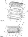
- FIG. 1a an intervertebral disc prosthesis 10 is shown according to a first exemplary embodiment.
- FIG. 1a an exploded view of the individual components of the intervertebral disc prosthesis 10 is shown.
- Fig. 1b a cross section through the intervertebral disc prosthesis 10 is shown.
- the intervertebral disc prosthesis 10 is, for example, a cervical intervertebral disc prosthesis.
- This comprises a caudal plate 20, a cranial plate 30 and a viscoelastic core 40 formed between the caudal plate 20 and the cranial plate 30.
- the caudal plate 20 has a recess 25 on the side 21 facing the cranial plate 30. As in particular in Fig. 1b is shown, the recess 25 has an undercut 28 .
- the core 40 is positively connected to the recess 25 of the caudal plate 20 .
- the viscoelastic core is injected or cast into the recess 25 .
- the viscoelastic core is an elastomeric core such as silicone or PCU.
- the caudal plate 20 with the recess 25 and the undercut 28 can first be made available.
- the caudal plate 20 is placed in an injection molding tool, for example.
- the viscoelastic material can then be cast or injected into the caudal plate.
- the caudal plate 20 has a corrugation 29 at least in sections on the underside or the side 22 facing the bone.
- the corrugation 29 is not formed over the entire underside 22 . Rather, a full-circumferential edge section 23 is formed, which serves as a bearing surface in the injection molding tool.
- a molding tool is then placed in order to then be able to form the viscoelastic core 40 .
- the edge area 27 of the side 21 of the caudal plate 20 serves as a support surface for the mold.
- the edge area 27 serves for sealing in the injection molding tool.
- the undercut 28 in the recess 25 is fully formed.
- the viscoelastic material is injected therein, a core 40 is formed and a positive connection of the core 40 with the caudal plate 20 is produced. This prevents the material from being able to be subsequently removed from the caudal plate 20 . Due to the positive connection of the core 40 with the recess 25 of the caudal plate 20, no additional fastening elements or additional materials such as adhesives or threads are necessary.
- the assembly of the intervertebral disc prosthesis 10 thus takes place more or less during the manufacturing phase.
- the cranial plate 30 has teeth 32 on the upper side or on the side 31 facing the bone.
- the cranial plate 30 also has two guide pins 34 .
- the guide pins 34 are formed on a connecting shoulder 35 of the cranial plate 30 .
- the cranial plate 30 is not connected to the nucleus.
- the cranial plate 30 rests on the core 40 only on the side 33 facing the caudal plate 20 .
- the guide pins 34 engage in the guide contour 50 of the viscoelastic core 40 .
- the guide contour 50 is in the form of two recesses 51 .
- the recesses 51 are essentially curved.
- the recesses 51 have a kidney shape. Accordingly, twisting of the cranial plate 30 in relation to the elastic core 40 is possible.
- the guide contour 50 is designed as a section of an elliptical groove 45 .
- the elastic core 40 is curved.
- the core 40 is curved in particular on the side 52 pointing towards the cranial plate 30 .
- the side 52 is arched both in the transverse direction Q and in the longitudinal direction L. Due to the groove 45 forming an elliptical path, an elastic core 40 is formed with a core center 41 which has an elliptical shape and is curved both in the longitudinal direction L and in the transverse direction Q. This also allows a tilting movement of the cranial plate 30 in relation to the elastic core 40.
- the side 52 of the core 40 is convexly curved in the transverse direction Q and in the longitudinal direction L.
- the core 40 is divided into several sections.
- the core center 41 is convexly curved in the transverse direction Q, whereas the area outside the groove 45 is concavely curved in the longitudinal direction L. This forms a core center 41 that protrudes significantly beyond the peripheral portion 42 of the core 40 .
- a double saddle function results.
- the caudal plate 20 is as in Figures 1a and 1b set forth, formed with a recess 27 and a full-circumferential undercut 28.
- an intervertebral disc prosthesis 10 is shown. This in turn consists of a caudal plate 20, a cranial plate 30 and an elastic core 40.
- the elastic core 40 in a recess 25 of the caudal Plate 20 is injected, wherein the recess 25 in turn has an undercut 28 formed over its entirety.
- the differences can be seen in particular in the shape of the guide pin 34 ′ of the cranial plate 30 and in the shape of the guide contour 50 of the elastic core 40 .
- the guide contour 50 essentially has the shape of a cross.
- the guide pin 34' has a shape complementary thereto.
- the guide contour 50 has a larger cross section than the guide pin 34 ′, so that the guide pin 34 ′ can move within the guide contour 50 .
- the recess 51 of the guide contour 50 is formed over the entire height of the elastic core 40.
- the elastic core 40 is in turn convexly curved both in the longitudinal direction L and in the transverse direction Q.
- Cross webs 56 connect to the cross shape 55 .
- the transverse webs 56 are in turn designed to be slightly curved.
- the guide contours 50 and/or the center of the core 41 form a kind of neutral zone. Since the recesses 51 of the guide contours 50 are larger than the engaging geometry of the guide pins 34 and 34', movement is permitted in interaction with the cranial plate 30, with the cranial plate 30 being guided in the elastic core 40.
- the dimension of the range of motion in the neutral zone is represented by the geometry of the guide contour 50 and the associated recess 51 .
- the movement is guided mechanically via the geometry of the elastic core 40 and is carried out with the lowest possible load or counterforce. Due to the geometry of the recess 51 or the guide contour 50 in the core 40 and the inverse geometry of the guide pin 34 or 34' of the cranial plate 30, the intervertebral disc prosthesis 10 is prevented from dislocating.
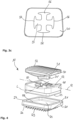
- FIG. 14 is an additional embodiment of a prosthetic spinal disc 10 having a cross-shaped guide pin 34' and a complementary shaped Recess 51 of the guide contour 50 shown.
- the elastic core 40 is concavely curved both in the transverse direction Q and in the longitudinal direction L. It is also conceivable that the elastic core 40, in particular the side 52, is only concave in the longitudinal direction L or only in the transverse direction Q.
Landscapes
- Health & Medical Sciences (AREA)
- Engineering & Computer Science (AREA)
- Biomedical Technology (AREA)
- Neurology (AREA)
- Orthopedic Medicine & Surgery (AREA)
- Cardiology (AREA)
- Oral & Maxillofacial Surgery (AREA)
- Transplantation (AREA)
- Heart & Thoracic Surgery (AREA)
- Vascular Medicine (AREA)
- Life Sciences & Earth Sciences (AREA)
- Animal Behavior & Ethology (AREA)
- General Health & Medical Sciences (AREA)
- Public Health (AREA)
- Veterinary Medicine (AREA)
- Prostheses (AREA)
Description
- Die Erfindung betrifft eine Bandscheibenprothese, umfassend eine kaudale Platte, eine kraniale Platte und einen zwischen der kaudalen Platte und der kranialen Platte ausgebildeten elastischen Kern, gemäß den Patentansprüchen 1 oder 2.
- Des Weiteren betrifft die Erfindung ein Verfahren zur Herstellung einer Bandscheibenprothese, insbesondere einer erfindungsgemäßen Bandscheibenprothese, gemäß Patentanspruch 8.
- Bandscheibenprothesen sind bewegungserhaltende Implantate, die den Höhenverlust bei Bandscheibenvorfällen ausgleichen und die natürliche Funktion und Beweglichkeit der Wirbelsäule, insbesondere einer Halswirbelsäule, weitgehend wiederherstellen. Die vorwiegend verwendeten Kugelgelenkprothesen beschränken die Bewegung nicht. Die Bewegung wird durch die Bänder und Muskeln limitiert. Kugelgelenkprothesen beruhen meist auf einer überlagerten Translationsbewegung, bei der der Kern selbst gleitet. Aufgrund der Limitation der Bewegung der Kugelgelenksprothesen durch die Bänder und Muskeln werden diese stark belastet, so dass Kopf- und Nackenschmerzen auftreten können.
- Eine bei Bandscheibenprothesen wünschenswerte Dämpfung muss die Kopflast beim Gehen aufnehmen und verteilen, so dass diese Kopflast nicht schlagartig auf die Wirbel einwirkt. Klinische Folgen fehlender Dämpfung sind Lastspitzen in der Berührungsfläche zwischen der Prothese und dem Wirbel, welche die Fixierung der Bandscheibenprothese beeinträchtigen. Ein Schlag auf bekannte Bandscheibenprothesen führt zu höheren Dislokations- und Versagensrisiken, wobei des Weiteren eine erhöhte Belastung auf alle Wirbel zu beobachten ist.
- Die Patentschriften
US 2012/150298 A1 undWO 2009/055796 A1 zeigen Beispiele von Bandscheibenprothesen, die eine kaudale Platte, eine kraniale Platte und einen zwischen der kaudalen Platte und der kranialen Platte ausgebildeten elastischen Kern offenbaren. In den jeweiligen Beispielen weist die kaudale Platte auf der zur kranialen Platte weisenden Seite eine Ausnehmung auf, wobei der Kern formschlüssig mit der Ausnehmung der kaudalen Platte verbunden ist und die kraniale Platte nicht mit dem Kern verbunden ist. Darüber hinaus weist die kraniale Platte mindestens einen Führungsstift auf, der in eine Führungskontur des Kerns beweglich eingreift. - Aus dem Vorgenannten ist es daher die Aufgabe der vorliegenden Erfindung, eine weiterentwickelte Bandscheibenprothese, insbesondere eine weiterentwickelte zervikale Bandscheibenprothese, anzugeben, welche die aufgezeigten Nachteile bisher bekannter Bandscheibenprothesen überwindet. Insbesondere soll eine Bandscheibenprothese zur Verfügung gestellt werden, die eine natürliche Bewegung der Halswirbelsäule mit sechs Freiheitsgraden ermöglicht.
- Des Weiteren ist es Aufgabe der vorliegenden Erfindung, ein weiterentwickeltes Verfahren zur Herstellung einer Bandscheibenprothese, insbesondere zur Herstellung einer erfindungsgemäßen Bandscheibenprothese, anzugeben.
- Die Lösung der Aufgabe erfolgt durch eine Bandscheibenprothese, die eine kaudale Platte, eine kraniale Platte und einen zwischen der kaudalen Platte und der kranialen Platte ausgebildeten elastischen Kern aufweist, gemäß Merkmalskombination der Patentansprüche 1 oder 2.
- Hinsichtlich des Verfahrens erfolgt die Lösung der Aufgabe durch ein Verfahren zur Herstellung einer Bandscheibenprothese, insbesondere einer erfindungsgemäßen Bandscheibenprothese, gemäß Merkmalskombination des Patentanspruches 11. Die jeweiligen Unteransprüche stellen mindestens zweckmäßige Ausgestaltungen und Weiterbildungen dar.
- Erfindungsgemäß weist die kaudale Platte auf der zur kranialen Platte weisenden Seite eine Ausnehmung auf, wobei der Kern formschlüssig mit der Ausnehmung der kaudalen Platte verbunden ist.
- Erfindungsgemäß ist der Kern haltend, nämlich formschlüssig, mit der kaudalen Platte verbunden. Insbesondere sind keine weiteren Zusatzwerkstoffe oder Zusatzbauteile zur Verbindung der kaudalen Platte mit dem elastischen Kern notwendig. Die kraniale Platte ist hingegen nicht mit dem elastischen Kern verbunden. Vielmehr liegt die kraniale Platte auf dem elastischen Kern auf. Aufgrund dessen wird eine Prothese aus zwei Platten und einem elastischen Kern zur Verfügung gestellt, die eine natürliche Bewegung der Wirbelsäule, insbesondere der Halswirbelsäule, mit sechs Freiheitsgraden ermöglicht.
- Bei den sechs Freiheitsgraden handelt es sich um eine Flexion, eine Extension sowie eine Seitneigung in axialer Richtung und um eine Rotation, eine Translation sowie eine Steifigkeit in kaudal-kranialer Richtung. Dabei ist der Bewegungsumfang in jede Richtung unterschiedlich und dem physiologischen Bewegungsumfang (range of motion) angepasst.
- In einer bevorzugten Ausführungsform der Erfindung weist die Ausnehmung zumindest abschnittsweise eine Hinterschneidung auf.
- Der Kern ist vorzugsweise in die Ausnehmung eingespritzt oder eingegossen, insbesondere mittels eines Urformverfahrens, besonders bevorzugt mittels eines Kunststoffspritzgießverfahrens oder Vakuumgussverfahrens eingespritzt oder eingegossen. Die Einspritzung bzw. das Eingießen eines Kerns in die Ausnehmung, insbesondere in eine Ausnehmung, die zumindest abschnittsweise eine Hinterschneidung aufweist, bildet eine formschlüssige Verbindung. Demnach ist es nicht notwendig, den Kern mit der kaudalen Platte zu verkleben. Des Weiteren ist es ebenfalls nicht notwendig, den Kern mit weiteren Hilfsmitteln, wie beispielsweise Fäden, mit der kaudalen Platte zu verbinden.
- Der Kern weist in einer besonders bevorzugten Ausführungsform viskoelastische Eigenschaften auf. Es ist möglich, dass der Kern aus einem Elastomer, insbesondere aus Silikon oder PCU, besteht. Die kraniale Platte ist nicht mit dem Kern verbunden. Die kraniale Platte kann allerdings am Kern anliegen bzw. auf dem Kern aufliegen. Das heißt, dass eine Berührung des Kerns durch die kraniale Platte keiner festen Verbindung entspricht.
- Die kraniale Platte weist erfindungsgemäß mindestens einen Führungsstift auf, der in eine Führungskontur des Kerns beweglich eingreift. Als Führungsstift sind auch Führungselemente mit größerem Durchmesser zu verstehen. Ein Führungsstift beschreibt mit anderen Worten ein Führungselement, das von der zum elastischen Kern weisenden Seite der kranialen Platte absteht.
- Der Kern weist eine, insbesondere komplementär zur Geometrie des Führungsstifts ausgebildete, Führungskontur auf. Die Führungskontur kann beispielsweise als Ausnehmung bzw. Materialaussparung ausgebildet sein.
- Der Führungsstift kann erfindungsgemäß im Querschnitt im Wesentlichen eine Kreuzform aufweisen, wobei die Führungskontur des Kerns vorzugsweise als eine komplementär zur Kreuzform ausgebildete Ausnehmung ausgebildet ist. Bei der Kreuzform des Führungsstiftes kann es sich auch um ein derartiges Kreuz handeln, das an den axialen Enden jeweils einen Quersteg aufweist. Die Ausnehmung des Kerns, die die Führungskontur bildet, weist eine hierzu komplementäre Form mit ebenfalls ausgebildeten Querstegen auf.
- Vorzugsweise ist die Ausnehmung bzw. Aussparung größer als der Querschnitt des Führungsstiftes ausgebildet. Dadurch wird insbesondere eine freie Translation ermöglicht. Die Dimension des Bewegungsumfangs in der Neutralzone wird über die Geometrie der Ausnehmung bzw. Materialaussparung abgebildet. Die geometrische Form der Ausnehmung bzw. die geometrische Form im Kern ermöglicht im Zusammenspiel mit der kranialen Platte eine Bewegung, wobei die Platte in dem elastischen Kern geführt wird. Mit anderen Worten greift mindestens ein Abschnitt der kranialen Platte in den Kern, insbesondere in eine Führungskontur des Kerns, ein.
- In einer weiteren Ausführungsform der Erfindung ist es möglich, dass die kraniale Platte mindestens zwei Führungsstifte aufweist, wobei die Führungskontur des Kerns als mindestens zwei gebogene, insbesondere nierenförmige, Ausnehmungen ausgebildet ist. Bei den beiden Führungsstiften handelt es sich vorzugsweise um Führungsstifte mit kreisrundem Querschnitt.
- Die beiden gebogenen Ausnehmungen können sowohl als Vertiefungen als auch als vollständige Ausnehmungen ausgebildet sein. Insbesondere sind die Ausnehmungen als gebogene, insbesondere nierenförmige, Langlöcher ausgebildet. Vorzugsweise liegen die mindestens zwei gebogenen, insbesondere nierenförmigen, Ausnehmungen auf einer gemeinsamen Ellipse. Des Weiteren ist es möglich, dass der Kern eine ellipsenförmige Nut aufweist, wobei in der ellipsenförmigen Nut die mindestens zwei gebogenen, insbesondere nierenförmigen, Ausnehmungen ausgebildet sind. Die ellipsenförmige Nut begrenzt eine mittige Ellipse. Die mittige Ellipse entspricht der Kernmitte.
- Der Kern kann des Weiteren auf der zur kranialen Platte weisenden Seite gewölbt ausgebildet sein. Vorzugsweise ist der Kern auf der erwähnten Seite sowohl in Längsrichtung als auch in Querrichtung gewölbt. Dies ermöglicht ein besonders einfaches Gleiten der kranialen Platte auf dem elastischen Kern.
- Die zum Knochen weisende Seite der kaudalen Platte und/oder die zum Knochen weisende Seite der kranialen Platte kann eine Verzahnung und/oder eine Riffelung aufweisen. Eine Verzahnung und/oder Riffelung dient zur Primärverankerung der kaudalen Platte und/oder der kranialen Platte an dem Knochen, insbesondere an den Wirbeln.
- In einer besonders bevorzugten Ausführungsform der Erfindung ist die Hinterschneidung in der Ausnehmung der kaudalen Platte vollumfänglich ausgebildet. Dies ermöglicht eine besonders gute Befestigung des elastischen Kerns in der Ausnehmung der kaudalen Platte. Die Ausnehmung weist insbesondere eine rechteckige Form auf.
- Der elastische, insbesondere viskoelastische, Kern muss abhängig von der Shore-Härte derart stabil sein, dass die mechanische Führung der (lastfreien) Bewegung der kranialen Platte in einer Neutralzone erlaubt wird. Dies betrifft den physiologischen Bewegungsbereich. In der Neutralzone wird die Bewegung mechanisch geführt und ist mit geringster Last bzw. Gegenlast durchführbar. Die mechanische Führung der Bewegung erfolgt über die Geometrie des Kerns.
- Am Maximum des physiologischen Bewegungsbereiches erfährt die Bewegung einen progressiven Kraftanstieg. Dies wird durch die Geometrie und durch das viskoelastische Verhalten des Kerns bedingt. Das heißt, je weiter das Wirbelsegment aus der Neutrallage bewegt wird, desto größer wird die Kraft. Ein harter Anschlag wird aufgrund der erfindungsgemäßen Ausbildung der Bandscheibenprothese vermieden. Der Bandapparat sowie die Muskeln der Wirbelsäule werden aufgrund der erfindungsgemäßen Bandscheibenprothese entlastet.
- Aufgrund der Geometrie der Führungskontur, insbesondere der im Kern ausgebildeten Ausnehmung, und dem dazu invers gestalteten Führungsstift der kranialen Platte wird eine Dislokation der Bandscheibenprothese verhindert. Eine Dislokation beschreibt das Verrutschen der kranialen Platte zum Kern.
- Der Bewegungsumfang der erfindungsgemäßen Bandscheibenprothese ist in jede Dimension einzeln durch die geometrische Ausführung des elastischen, insbesondere viskoelastischen, Kerns auf das physiologische Maß beschränkt und definierbar. Aus dem Stand der Technik existieren hierzu lediglich dämpfende Prothesen mit einem progressiven Kraftanstieg, deren Bewegungsumfang jedoch in jede Richtung gleich ist.
- Der elastische Kern nimmt im implantierten Zustand die Kopflast (follower load) auf und dämpft zusätzlich bei Bewegung die Kraft. Mit anderen Worten senkt der elastische Kern bei Bewegung die Kraft ab. In axialer Richtung wird somit eine gewisse Steifigkeit realisiert. Durch die Höhenveränderung des elastischen Kerns wird somit eine axiale Stoßlast abgefangen.
- Mit Hilfe der Verzahnung und/oder Riffelung der kaudalen Platte und/oder der kranialen Platte wird eine Primärstabilität der eingesetzten Bandscheibenprothese gewährleistet. Die Verzahnung und/oder Riffelung begünstigen das Verwachsen der kranialen Platte und/oder der kaudalen Platte mit dem Knochen. Der finale Halt der implantierten Bandscheibenprothese wird durch sekundäres Verwachsen mit dem Wirbelknochen erreicht.
- Die kraniale Platte und/oder die kaudale Platte kann/können aus Metall und/oder Keramik und/oder Kunststoff, insbesondere Polyetheretherketon (PEEK), gebildet sein. Es ist möglich, unterschiedliche Materialpaarung für die kraniale und kaudale Platte zu verwenden.
- Die Konstruktion der Bandscheibenprothese ermöglicht es, dass die Bandscheibenprothese derart anatomisch angepasst ist, dass diese besonders vorteilhaft in das Bandscheibenfach eingesetzt werden kann, an dem Uncovertebralgelenk anliegt und die natürliche Lordose unterstützt.
- Vorab ist kein spezielles Präparieren der Knochensubstanz durch Fräsen oder Einschlagen von Kielen notwendig. Dies vereinfacht die Operationstechnik, so dass das Risiko einer iatrogenen Schädigung wie z.B. Nervenschädigungen oder Abbruch von Knochenfragmenten oder der Gefahr der Prothesen-Dislokation durch fehlende Wirbelteile vermindert werden.
- In einer besonders bevorzugten Ausführungsform der Erfindung ist die Bandscheibenprothese als eine zervikale Bandscheibenprothese ausgebildet.
- Ein weiterer nebengeordneter Aspekt der Erfindung betrifft ein Verfahren zur Herstellung einer Bandscheibenprothese, insbesondere einer zuvor beschriebenen erfindungsgemäßen Bandscheibenprothese.
- Das erfindungsgemäße Verfahren zur Herstellung einer erfindungsgemäßen Bandscheibenprothese beruht auf den Verfahrensschritten:
- a) Bereitstellen einer kaudalen Platte mit einer Ausnehmung, die vorzugsweise zumindest abschnittsweise eine Hinterschneidung aufweist,
- b) Einspritzen oder Eingießen eines elastischen, insbesondere viskoelastischen, Materials in die Ausnehmung und Bilden eines elastischen, insbesondere viskoelastischen, Kerns.
- Vorzugsweise wird die kaudale Platte vor Schritt b) in eine Form, insbesondere in ein Spritzgusswerkzeug, eingelegt.
- Vorzugsweise ist die (erfindungsgemäße) kaudale Platte auf der zum Knochen weisenden Seite derart ausgebildet, dass eine Verzahnung und/oder Riffelung nicht vollflächig ausgebildet ist. Insbesondere ist es möglich, dass auf der zum Knochen weisenden Seite der kaudalen Platte ein Randbereich ohne Verzahnung und/oder Riffelung ausgebildet ist, sodass die kaudale Platte zumindest abschnittsweise plan aufliegend in eine Form, insbesondere in ein Spritzgusswerkzeug, eingelegt werden kann. Mit anderen Worten dient der beschriebene Randbereich beispielsweise als Auflagefläche im Spritzgusswerkzeug.
- In einer weiteren Ausführungsform des erfindungsgemäßen Verfahrens weist die (erfindungsgemäße) kaudale Platte auf der zum Kern weisenden Seite ebenfalls einen Randbereich/Randabschnitt auf, der zur Abdichtung im Werkzeug dient. Insbesondere wird auf den Randbereich/Randabschnitt ein Formwerkzeug aufgelegt, um anschließend den elastischen Kern bilden zu können. Mit anderen Worten dient als Auflagefläche für das Formwerkzeug ein Randbereich/Randabschnitt der Seite der kaudalen Platte, die im fertig montierten Zustand zum Kern weist. Der Randbereich dient zur Abdichtung im Spritzgusswerkzeug.
- Gemäß einem Schritt c) folgt nach dem Bilden eines elastischen, insbesondere viskoelastischen, Kerns, ein Auflegen einer kranialen Platte auf den Kern derart, dass mindestens ein Führungsstift der kranialen Platte in eine Führungskontur des Kerns beweglich eingreift.
- Die Erfindung wird im Folgenden anhand mehrerer Ausführungsbeispiele unter Bezugnahme auf die beigefügten, schematischen Zeichnungen näher erläutert.
- Darin zeigen:
- Fig. 1a - 1b
- mehrere Ansichten auf eine erfindungsgemäße Bandscheibenprothese gemäß einem ersten Ausführungsbeispiel;
- Fig. 2a und 2b
- verschiedene Ansichten auf eine erfindungsgemäße Bandscheibenprothese gemäß einem zweiten Ausführungsbeispiel;
- Fig. 3a - 3c
- mehrere Ansichten auf eine erfindungsgemäße Bandscheibenprothese gemäß einem dritten Ausführungsbeispiel; und
- Fig. 4
- eine Explosionsdarstellung einer erfindungsgemäßen Bandscheibenprothese gemäß einem vierten Ausführungsbeispiel.
- In der nachfolgenden Beschreibung werden für gleiche und gleichwirkende Teile dieselben Bezugsziffern verwendet.
- In den
Fig. 1a und 1b ist eine Bandscheibenprothese 10 gemäß einem ersten Ausführungsbeispiel dargestellt. InFig. 1a ist eine Explosionsdarstellung der einzelnen Bestandteile der Bandscheibenprothese 10 dargestellt. InFig. 1b ist hingegen ein Querschnitt durch die Bandscheibenprothese 10 dargestellt. - Es ist darauf hinzuweisen, dass die einzelnen Elemente der Bandscheibenprothese 10 im tatsächlich fixierten bzw. hergestellten Zustand nicht wie in
Fig. 1a dargestellt auseinandergenommen werden können. Dies ist vor allen Dingen aufgrund des erfindungsgemäßen Herstellungsverfahrens nicht ohne weiteres möglich. - Bei der Bandscheibenprothese 10 handelt es sich beispielsweise um eine zervikale Bandscheibenprothese. Diese umfasst eine kaudale Platte 20, eine kraniale Platte 30 und einen zwischen der kaudalen Platte 20 und der kranialen Platte 30 ausgebildeten viskoelastischen Kern 40. Die kaudale Platte 20 weist auf der zur kranialen Platte 30 weisenden Seite 21 eine Ausnehmung 25 auf. Wie insbesondere in
Fig. 1b dargestellt ist, weist die Ausnehmung 25 eine Hinterschneidung 28 auf. - Der Kern 40 ist formschlüssig mit der Ausnehmung 25 der kaudalen Platte 20 verbunden. Insbesondere ist der viskoelastische Kern in die Ausnehmung 25 eingespritzt oder eingegossen. Bei dem viskoelastischen Kern handelt es sich um einen Kern aus Elastomer, wie beispielsweise Silikon oder PCU.
- Im Rahmen des erfindungsgemäßen Herstellungsverfahrens kann zunächst die kaudale Platte 20 mit der Ausnehmung 25 sowie der Hinterschneidung 28 zur Verfügung gestellt werden. Die kaudale Platte 20 wird beispielsweise in ein Spritzgusswerkzeug eingelegt. Anschließend kann das viskoelastische Material in die kaudale Platte eingegossen oder eingespritzt werden.
- Die kaudale Platte 20 weist auf der Unterseite bzw. der zum Knochen weisenden Seite 22 zumindest abschnittsweise eine Riffelung 29 auf. Im dargestellten Beispiel ist die Riffelung 29 nicht über die gesamte Unterseite 22 ausgebildet. Vielmehr wird ein vollumfänglicher Randabschnitt 23 gebildet, der als Auflagefläche im Spritzgusswerkzeug dient. Nach Einlegen der kaudalen Platte 20 in das Spritzgusswerkzeug wird anschließend ein Formwerkzeug aufgelegt, um anschließend den viskoelastischen Kern 40 bilden zu können. Als Auflagefläche für das Formwerkzeug dient hierbei der Randbereich 27 der Seite 21 der kaudalen Platte 20. Der Randbereich 27 dient zur Abdichtung im Spritzgusswerkzeug.
- Die Hinterschneidung 28 in der Ausnehmung 25 ist vollumfänglich ausgebildet. Darin wird das viskoelastische Material eingespritzt, ein Kern 40 gebildet und eine formschlüssige Verbindung des Kerns 40 mit der kaudalen Platte 20 hergestellt. Somit wird verhindert, dass das Material aus der kaudalen Platte 20 anschließend entnehmbar ist. Aufgrund der formschlüssigen Verbindung des Kerns 40 mit der Ausnehmung 25 der kaudalen Platte 20 sind keine zusätzlichen Befestigungselemente oder Zusatzwerkstoffe wie z.B. Klebemittel oder Fäden notwendig. Die Montage der Bandscheibenprothese 10 findet somit quasi während der Herstellungsphase statt.
- Die kraniale Platte 30 weist auf der Oberseite bzw. der zum Knochen weisenden Seite 31 eine Verzahnung 32 auf. Die kraniale Platte 30 weist des Weiteren zwei Führungsstifte 34 auf. Die Führungsstifte 34 sind auf einem Verbindungsabsatz 35 der kranialen Platte 30 ausgebildet.
- Die kraniale Platte 30 ist nicht mit dem Kern verbunden. Die kraniale Platte 30 liegt lediglich auf der zur kaudalen Platte 20 weisenden Seite 33 auf dem Kern 40 auf. Die Führungsstifte 34 greifen in die Führungskontur 50 des viskoelastischen Kerns 40 ein. Die Führungskontur 50 ist im dargestellten Beispiel in Form von zwei Ausnehmungen 51 ausgebildet. Die Ausnehmungen 51 sind im Wesentlichen gebogen ausgebildet. Insbesondere weisen die Ausnehmungen 51 eine Nierenform auf. Demnach ist eine Verdrehung der kranialen Platte 30 in Relation zum elastischen Kern 40 möglich. Die Führungskontur 50 ist als Abschnitt einer ellipsenförmigen Nut 45 ausgebildet.
- Der elastische Kern 40 ist des Weiteren gewölbt ausgebildet. Der Kern 40 ist insbesondere auf der zur kranialen Platte 30 weisenden Seite 52 gewölbt ausgebildet. Die Seite 52 ist sowohl in Querrichtung Q als auch in Längsrichtung L gewölbt ausgebildet. Aufgrund der Nut 45, die eine Ellipsenbahn bildet, ist ein elastischer Kern 40 mit einer Kernmitte 41 gebildet, die eine Ellipsenform aufweist und sowohl in Längsrichtung L als auch in Querrichtung Q gewölbt ist. Dies ermöglicht auch eine Kippbewegung der kranialen Platte 30 in Relation zum elastischen Kern 40.
- In den
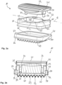
Fig. 2a und 2b ist eine zu denFig. 1a und 1b ähnliche Ausführungsform einer zervikalen Bandscheibenprothese 10 dargestellt. Im Folgenden wird lediglich auf die Unterschiede eingegangen. Diese sind insbesondere im Zusammenhang mit der Ausbildung des elastischen Kerns 40 zu erkennen. - In den
Fig. 1a und 1b ist die Seite 52 des Kerns 40 in Querrichtung Q und in Längsrichtung L konvex gewölbt. - In
Fig. 2a ist der Kern 40 in mehrere Teilabschnitte unterteilt. Die Kernmitte 41 ist in Querrichtung Q konvex gekrümmt, wohingegen der Bereich außerhalb der Nut 45 in Längsrichtung L konkav gewölbt ist. Dadurch wird eine Kernmitte 41 gebildet, die deutlich über den Umfangsabschnitt 42 des Kerns 40 hervorsteht. Es ergibt sich eine Doppel-Sattel-Funktion. - Die kaudale Platte 20 ist wie bereits in
Fig. 1a und 1b dargelegt, mit einer Ausnehmung 27 und einer vollumfänglichen Hinterschneidung 28 ausgebildet. - In den
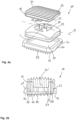
Fig. 3a bis 3c ist eine weitere Ausführungsform einer Bandscheibenprothese 10 dargestellt. Diese besteht wiederum aus einer kaudalen Platte 20, einer kranialen Platte 30 und einem elastischen Kern 40. - Insbesondere in der
Fig. 3b ist zu erkennen, dass auch in diesem Ausführungsbeispiel der elastische Kern 40 in eine Ausnehmung 25 der kaudalen Platte 20 eingespritzt ist, wobei die Ausnehmung 25 wiederum eine vollumfänglich ausgebildete Hinterschneidung 28 aufweist. - Die Unterschiede sind insbesondere in der Form des Führungsstiftes 34' der kranialen Platte 30 sowie in der Formgebung der Führungskontur 50 des elastischen Kerns 40 zu erkennen. Die Führungskontur 50 weist im Wesentlichen eine Kreuzform auf. Der Führungsstift 34' weist eine hierzu komplementäre Form auf. Die Führungskontur 50 weist einen größeren Querschnitt als der Führungsstift 34' auf, so dass sich der Führungsstift 34' innerhalb der Führungskontur 50 bewegen kann. Wie der
Fig. 3b zu entnehmen ist, ist die Ausnehmung 51 der Führungskontur 50 über die gesamte Höhe des elastischen Kerns 40 ausgebildet. Der elastische Kern 40 ist wiederum sowohl in Längsrichtung L als auch in Querrichtung Q konvex gewölbt. - In
Fig. 3c ist die Form der Führungskontur 50 und somit die Form des komplementär ausgebildeten Führungsstiftes 34' näher dargestellt. An die Kreuzform 55 schließen sich Querstege 56 an. Die Querstege 56 sind wiederum leicht gewölbt ausgebildet. - Die Führungskonturen 50 und/oder die Kernmitte 41 (dies betrifft die Ausführungsbeispiele der
Fig. 1a bis 2b ) bilden eine Art Neutralzone. Da die Ausnehmungen 51 der Führungskonturen 50 größer als die eingreifende Geometrie der Führungsstifte 34 und 34' sind, wird im Zusammenspiel mit der kranialen Platte 30 eine Bewegung erlaubt, wobei die kraniale Platte 30 im elastischen Kern 40 geführt wird. - Die Dimension des Bewegungsumfangs in der Neutralzone wird über die Geometrie der Führungskontur 50 sowie der zugehörigen Ausnehmung 51 abgebildet. In der Neutralzone wird die Bewegung mechanisch über die Geometrie des elastischen Kerns 40 geführt und mit geringster Last bzw. Gegenkraft durchgeführt. Aufgrund der Geometrie der Ausnehmung 51 bzw. der Führungskontur 50 im Kern 40 und der invers gestalteten Geometrie des Führungsstiftes 34 bzw. 34' der kranialen Platte 30 wird verhindert, dass es zu einer Dislokation der Bandscheibenprothese 10 kommt.
- In
Fig. 4 ist eine zusätzliche Ausführungsform einer Bandscheibenprothese 10 mit einem kreuzförmigen Führungsstift 34' und einer komplementär ausgebildeten Ausnehmung 51 der Führungskontur 50 dargestellt. InFig. 4 ist der elastische Kern 40 sowohl in Querrichtung Q als auch in Längsrichtung L konkav gewölbt. Es ist auch denkbar, dass der elastische Kern 40, insbesondere die Seite 52 lediglich in Längsrichtung L oder lediglich in Querrichtung Q konkav geformt ist. -
- 10
- Bandscheibenprothese
- 20
- Kaudale Platte
- 21
- Seite kaudale Platte
- 22
- Unterseite
- 23
- Randabschnitt
- 25
- Ausnehmung
- 27
- Randbereich
- 28
- Hinterschneidung
- 29
- Riffelung
- 30
- Kraniale Platte
- 31
- Oberseite
- 32
- Verzahnung
- 33
- Seite kraniale Platte
- 34, 34'
- Führungsstift
- 35
- Verbindungsabsatz
- 40
- Elastischer Kern
- 41
- Kernmitte
- 42
- Umfangsabschnitt
- 45
- Nut
- 50
- Führungskontur
- 51
- Ausnehmung
- 52
- Seite
- 53
- Unterseite
- 55
- Kreuzform
- 56
- Querstrebe
- L
- Längsrichtung
- Q
- Querrichtung
Claims (10)
- Bandscheibenprothese (10), umfassend eine kaudale Platte (20), eine kraniale Platte (30) und einen zwischen der kaudalen Platte (20) und der kranialen Platte (30) ausgebildeten elastischen Kern (40),wobeidie kaudale Platte (20) auf der zur kranialen Platte (30) weisenden Seite (21) eine Ausnehmung (25) aufweist, wobei die kraniale Platte (30) nicht mit dem Kern (40) verbunden ist,dadurch gekennzeichnet, dassder Kern (40) formschlüssig mit der Ausnehmung (25) der kaudalen Platte (20) verbunden ist, wobei die kraniale Platte (30) mindestens zwei Führungsstifte (34) aufweist, die in eine Führungskontur (50) des Kerns (40) beweglich eingreifen und die Führungskontur (50) des Kerns (40) als mindestens zwei gebogene, insbesondere nierenförmige, Ausnehmungen (51) ausgebildet ist.
- Bandscheibenprothese (10), umfassend eine kaudale Platte (20), eine kraniale Platte (30) und einen zwischen der kaudalen Platte (20) und der kranialen Platte (30) ausgebildeten elastischen Kern (40),wobeidie kaudale Platte (20) auf der zur kranialen Platte (30) weisenden Seite (21) eine Ausnehmung (25) aufweist, wobei die kraniale Platte (30) nicht mit dem Kern (40) verbunden ist,dadurch gekennzeichnet, dassder Kern (40) formschlüssig mit der Ausnehmung (25) der kaudalen Platte (20) verbunden ist, wobei die kraniale Platte (30) mindestens einen Führungsstift (34') aufweist, der in eine Führungskontur (50) des Kerns (40) beweglich eingreift und der Führungsstift (34') im Querschnitt im Wesentlichen eine Kreuzform aufweist und die Führungskontur (50) des Kerns (40) als eine komplementär zur Kreuzform ausgebildete Ausnehmung (51) ausgebildet ist.
- Bandscheibenprothese (10) nach Anspruch 1 oder 2,
dadurch gekennzeichnet, dass
der Kern (40) in die Ausnehmung (25) eingespritzt oder eingegossen, insbesondere mittels eines Urformverfahrens, besonders bevorzugt mittels eines Kunststoffspritzgießverfahrens oder Vakuumgussverfahrens eingespritzt oder eingegossen, ist. - Bandscheibenprothese (10) nach Anspruch 1, 2 oder 3,
dadurch gekennzeichnet, dass
der Kern (40) viskoelastische Eigenschaften aufweist und/oder aus einem Elastomer, insbesondere aus Silikon oder PCU, besteht. - Bandscheibenprothese (10) nach einem der vorhergehenden Ansprüche,
dadurch gekennzeichnet, dass
der Kern (40) auf der zur kranialen Platte (30) weisenden Seite (52) gewölbt, insbesondere in Längsrichtung (L) und in Querrichtung (Q) gewölbt, ausgebildet ist. - Bandscheibenprothese (10) nach einem der vorhergehenden Ansprüche,
dadurch gekennzeichnet, dass
die zum Knochen weisende Seite (22) der kaudalen Platte (20) und/oder die zum Knochen weisende Seite (31) der kranialen Platte (30) eine Verzahnung (32) und/oder Riffelung (29) aufweist. - Bandscheibenprothese (10) nach einem der vorhergehenden Ansprüche,
dadurch gekennzeichnet, dass
in der Ausnehmung (25) der kaudalen Platte (20) zumindest abschnittsweise, insbesondere vollumfänglich, eine Hinterschneidung (28) ausgebildet ist. - Verfahren zur Herstellung einer Bandscheibenprothese (10), insbesondere einer Bandscheibenprothese nach einem der Ansprüche 1 bis 7,
gekennzeichnet durch
die Verfahrensschritte:a) Bereitstellen einer kaudalen Platte (20) mit einer Ausnehmung (25), die vorzugsweise zumindest abschnittsweise eine Hinterschneidung (28) aufweist,b) Einspritzen und/oder Eingießen eines elastischen, insbesondere viskoelastischen, Materials in die Ausnehmung (25) und Bilden eines elastischen, insbesondere viskoelastischen, Kerns (40). - Verfahren nach Anspruch 8,
dadurch gekennzeichnet, dass
die kaudale Platte (20) vor Schritt b) in eine Form, insbesondere in ein Spritzgusswerkzeug, eingelegt wird. - Verfahren nach Anspruch 8 oder 9,
gekennzeichnet durch
c) Auflegen einer kranialen Platte (30) auf den Kern (40) derart, dass mindestens ein Führungsstift (34, 34') der kranialen Platte (30) in eine Führungskontur (50) des Kerns (40) beweglich eingreift.
Applications Claiming Priority (2)
| Application Number | Priority Date | Filing Date | Title |
|---|---|---|---|
| DE102016124877.0A DE102016124877B4 (de) | 2016-12-19 | 2016-12-19 | Bandscheibenprothese und Verfahren zur Herstellung einer Bandscheibenprothese |
| PCT/EP2017/081674 WO2018114334A1 (de) | 2016-12-19 | 2017-12-06 | Bandscheibenprothese und verfahren zur herstellung einer bandscheibenprothese |
Publications (2)
| Publication Number | Publication Date |
|---|---|
| EP3554427A1 EP3554427A1 (de) | 2019-10-23 |
| EP3554427B1 true EP3554427B1 (de) | 2023-08-09 |
Family
ID=60782184
Family Applications (1)
| Application Number | Title | Priority Date | Filing Date |
|---|---|---|---|
| EP17818079.0A Active EP3554427B1 (de) | 2016-12-19 | 2017-12-06 | Bandscheibenprothese und verfahren zur herstellung einer bandscheibenprothese |
Country Status (7)
| Country | Link |
|---|---|
| US (1) | US11540925B2 (de) |
| EP (1) | EP3554427B1 (de) |
| JP (1) | JP6941891B2 (de) |
| AU (1) | AU2017380627B2 (de) |
| DE (1) | DE102016124877B4 (de) |
| ES (1) | ES2963350T3 (de) |
| WO (1) | WO2018114334A1 (de) |
Families Citing this family (6)
| Publication number | Priority date | Publication date | Assignee | Title |
|---|---|---|---|---|
| CN108836579B (zh) * | 2018-07-06 | 2023-07-28 | 北京爱康宜诚医疗器材有限公司 | 人工椎间盘假体 |
| CN110025408B (zh) * | 2019-04-17 | 2023-04-25 | 福州大学 | 非融合颈椎间盘假体及其装配方法 |
| US11197765B2 (en) | 2019-12-04 | 2021-12-14 | Robert S. Bray, Jr. | Artificial disc replacement device |
| US11839554B2 (en) | 2020-01-23 | 2023-12-12 | Robert S. Bray, Jr. | Method of implanting an artificial disc replacement device |
| KR102712116B1 (ko) * | 2022-06-16 | 2024-10-02 | 주식회사 허브바이오텍 | 요추용 인공디스크 |
| US12599487B2 (en) * | 2023-07-13 | 2026-04-14 | Sg, Llc | Tools and implants for lateral disc replacement |
Family Cites Families (22)
| Publication number | Priority date | Publication date | Assignee | Title |
|---|---|---|---|---|
| US5676701A (en) * | 1993-01-14 | 1997-10-14 | Smith & Nephew, Inc. | Low wear artificial spinal disc |
| US7601174B2 (en) * | 2000-08-08 | 2009-10-13 | Warsaw Orthopedic, Inc. | Wear-resistant endoprosthetic devices |
| RU2303422C2 (ru) * | 2002-03-12 | 2007-07-27 | Сервитек Инк. | Межпозвонковый протез и система межпозвонковых протезов, в частности для шейного отдела позвоночника |
| US6793678B2 (en) * | 2002-06-27 | 2004-09-21 | Depuy Acromed, Inc. | Prosthetic intervertebral motion disc having dampening |
| WO2004105638A2 (en) * | 2003-05-27 | 2004-12-09 | Spinalmotion, Inc. | Prosthetic disc for intervertebral insertion |
| FR2856587B1 (fr) * | 2003-06-26 | 2006-02-24 | Scient X | Prothese discale pour vertebres cervicales a debattement controle |
| US7695517B2 (en) * | 2003-12-10 | 2010-04-13 | Axiomed Spine Corporation | Apparatus for replacing a damaged spinal disc |
| US20050165407A1 (en) * | 2004-01-23 | 2005-07-28 | Diaz Robert L. | Disk arthroplasty instrumentation and implants |
| US7250060B2 (en) * | 2004-01-27 | 2007-07-31 | Sdgi Holdings, Inc. | Hybrid intervertebral disc system |
| US8454699B2 (en) * | 2004-06-30 | 2013-06-04 | Synergy Disc Replacement, Inc | Systems and methods for vertebral disc replacement |
| US9237958B2 (en) * | 2004-06-30 | 2016-01-19 | Synergy Disc Replacement Inc. | Joint prostheses |
| KR100939507B1 (ko) | 2004-12-06 | 2010-02-03 | 액시오메드 스파인 코포레이션 | 척추 디스크 대체 방법 및 장치 |
| FR2887435B1 (fr) * | 2005-06-24 | 2007-10-05 | Abbott Spine Sa | Prothese de disque intervertebral |
| US7887592B2 (en) | 2007-02-14 | 2011-02-15 | Spinal Kinetics, Inc. | Prosthetic intervertebral discs assemblies having compressible core elements with enhanced torque transmission |
| US8956412B2 (en) * | 2007-06-22 | 2015-02-17 | Axiomed, LLC | Artificial disc |
| US8182534B2 (en) * | 2007-09-27 | 2012-05-22 | K2M, Inc. | Orthopedic device assembly with elements coupled by a retaining structure |
| US9265617B2 (en) * | 2010-10-06 | 2016-02-23 | Karin Buettner-Janz | Prosthesis for cervical and lumbar spine |
| US8496713B2 (en) * | 2010-12-10 | 2013-07-30 | Globus Medical, Inc. | Spine stabilization device and methods |
| US8998991B2 (en) | 2011-02-23 | 2015-04-07 | Globus Medical, Inc. | Six degree spine stabilization devices and methods |
| US8449616B2 (en) | 2011-03-15 | 2013-05-28 | Axiomed Spine Corporation | Apparatus for replacing a damaged spinal disc |
| FR2981562B1 (fr) * | 2011-10-19 | 2014-12-19 | Medicrea International | Prothese de disque intervertebral |
| US9198770B2 (en) | 2013-07-31 | 2015-12-01 | Globus Medical, Inc. | Artificial disc devices and related methods of use |
-
2016
- 2016-12-19 DE DE102016124877.0A patent/DE102016124877B4/de active Active
-
2017
- 2017-12-06 EP EP17818079.0A patent/EP3554427B1/de active Active
- 2017-12-06 US US16/466,536 patent/US11540925B2/en active Active
- 2017-12-06 JP JP2019553629A patent/JP6941891B2/ja active Active
- 2017-12-06 WO PCT/EP2017/081674 patent/WO2018114334A1/de not_active Ceased
- 2017-12-06 ES ES17818079T patent/ES2963350T3/es active Active
- 2017-12-06 AU AU2017380627A patent/AU2017380627B2/en active Active
Also Published As
| Publication number | Publication date |
|---|---|
| DE102016124877B4 (de) | 2019-02-07 |
| DE102016124877A1 (de) | 2018-06-21 |
| AU2017380627A1 (en) | 2019-07-11 |
| ES2963350T3 (es) | 2024-03-26 |
| JP6941891B2 (ja) | 2021-09-29 |
| EP3554427A1 (de) | 2019-10-23 |
| WO2018114334A1 (de) | 2018-06-28 |
| JP2020501863A (ja) | 2020-01-23 |
| US11540925B2 (en) | 2023-01-03 |
| AU2017380627B2 (en) | 2020-08-13 |
| US20210298914A1 (en) | 2021-09-30 |
Similar Documents
| Publication | Publication Date | Title |
|---|---|---|
| EP1620023B1 (de) | Dynamische verankerungsvorrichtung und dynamische stabilisierungseinrichtung für knochen, insbesondere für wirbel, mit einer derartigen verankerungsvorrichtung | |
| DE102016124877B4 (de) | Bandscheibenprothese und Verfahren zur Herstellung einer Bandscheibenprothese | |
| DE69102369T2 (de) | Bandscheibenprothese und instrumente für ihre implantation. | |
| EP2114274B1 (de) | Plattenimplantat, insbesondere für die anwendung an einer wirbelsäule | |
| EP1593357B1 (de) | Flexibler Platzhalter | |
| EP1572039B1 (de) | Zwischenwirbelimplantat | |
| DE60018924T2 (de) | Künstliches zwischenwirbelimplantat | |
| EP1872748B1 (de) | Implantat zum Einsetzen zwischen zwei Wirbelkörper der Wirbelsäule | |
| DE69220852T2 (de) | Stossdämpfende Vorrichtung zur Zwischenwirbelstabilisierung | |
| EP1648351B1 (de) | Zwischenwirbelimplantat mit temporären blockiermitteln | |
| EP1388323B1 (de) | Dynamische Stabilisierungseinrichtung für Knochen, insbesondere für Wirbel | |
| EP1534193B1 (de) | Zwischenwirbelimplantat mit dreiteiligem gelenk | |
| DE69534978T2 (de) | Einstellbarer Wirbelkörper-Ersatz | |
| WO2004026186A1 (de) | Implantat mit zweiteiligem gelenk | |
| DE10323363A1 (de) | Implantat zum Einsetzen zwischen Wirbelkörper der Wirbelsäule | |
| EP2764850A1 (de) | Halswirbelimplantat für Hunde | |
| DE202007003420U1 (de) | Zwischenwirbelprothese | |
| DE20315613U1 (de) | Zwischenwirbelimplantat | |
| EP3035892B1 (de) | Modulare prothesen | |
| DE102007042946B4 (de) | Implantierbarer, prothetischer Wirbelkörperersatz | |
| EP3359094B1 (de) | Künstliches gelenkimplantat | |
| EP1613249A1 (de) | Hüftprothese | |
| EP2589350B1 (de) | Dynamische Stabilisierungseinrichtung für Knochen | |
| EP2135586B1 (de) | Implantat zum Einsetzen zwischen Wirbelkörper der Wirbelsäule | |
| WO2014076084A1 (de) | Facettengelenkprothese |
Legal Events
| Date | Code | Title | Description |
|---|---|---|---|
| STAA | Information on the status of an ep patent application or granted ep patent |
Free format text: STATUS: UNKNOWN |
|
| STAA | Information on the status of an ep patent application or granted ep patent |
Free format text: STATUS: THE INTERNATIONAL PUBLICATION HAS BEEN MADE |
|
| PUAI | Public reference made under article 153(3) epc to a published international application that has entered the european phase |
Free format text: ORIGINAL CODE: 0009012 |
|
| STAA | Information on the status of an ep patent application or granted ep patent |
Free format text: STATUS: REQUEST FOR EXAMINATION WAS MADE |
|
| 17P | Request for examination filed |
Effective date: 20190605 |
|
| AK | Designated contracting states |
Kind code of ref document: A1 Designated state(s): AL AT BE BG CH CY CZ DE DK EE ES FI FR GB GR HR HU IE IS IT LI LT LU LV MC MK MT NL NO PL PT RO RS SE SI SK SM TR |
|
| AX | Request for extension of the european patent |
Extension state: BA ME |
|
| DAV | Request for validation of the european patent (deleted) | ||
| DAX | Request for extension of the european patent (deleted) | ||
| GRAP | Despatch of communication of intention to grant a patent |
Free format text: ORIGINAL CODE: EPIDOSNIGR1 |
|
| STAA | Information on the status of an ep patent application or granted ep patent |
Free format text: STATUS: GRANT OF PATENT IS INTENDED |
|
| INTG | Intention to grant announced |
Effective date: 20220705 |
|
| GRAJ | Information related to disapproval of communication of intention to grant by the applicant or resumption of examination proceedings by the epo deleted |
Free format text: ORIGINAL CODE: EPIDOSDIGR1 |
|
| STAA | Information on the status of an ep patent application or granted ep patent |
Free format text: STATUS: REQUEST FOR EXAMINATION WAS MADE |
|
| INTC | Intention to grant announced (deleted) | ||
| GRAP | Despatch of communication of intention to grant a patent |
Free format text: ORIGINAL CODE: EPIDOSNIGR1 |
|
| STAA | Information on the status of an ep patent application or granted ep patent |
Free format text: STATUS: GRANT OF PATENT IS INTENDED |
|
| INTG | Intention to grant announced |
Effective date: 20230223 |
|
| RAP3 | Party data changed (applicant data changed or rights of an application transferred) |
Owner name: NGMEDICAL GMBH |
|
| GRAS | Grant fee paid |
Free format text: ORIGINAL CODE: EPIDOSNIGR3 |
|
| GRAA | (expected) grant |
Free format text: ORIGINAL CODE: 0009210 |
|
| STAA | Information on the status of an ep patent application or granted ep patent |
Free format text: STATUS: THE PATENT HAS BEEN GRANTED |
|
| P01 | Opt-out of the competence of the unified patent court (upc) registered |
Effective date: 20230602 |
|
| AK | Designated contracting states |
Kind code of ref document: B1 Designated state(s): AL AT BE BG CH CY CZ DE DK EE ES FI FR GB GR HR HU IE IS IT LI LT LU LV MC MK MT NL NO PL PT RO RS SE SI SK SM TR |
|
| REG | Reference to a national code |
Ref country code: GB Ref legal event code: FG4D Free format text: NOT ENGLISH |
|
| REG | Reference to a national code |
Ref country code: CH Ref legal event code: EP |
|
| REG | Reference to a national code |
Ref country code: DE Ref legal event code: R096 Ref document number: 502017015209 Country of ref document: DE |
|
| REG | Reference to a national code |
Ref country code: IE Ref legal event code: FG4D Free format text: LANGUAGE OF EP DOCUMENT: GERMAN |
|
| REG | Reference to a national code |
Ref country code: LT Ref legal event code: MG9D |
|
| REG | Reference to a national code |
Ref country code: NL Ref legal event code: MP Effective date: 20230809 |
|
| PG25 | Lapsed in a contracting state [announced via postgrant information from national office to epo] |
Ref country code: GR Free format text: LAPSE BECAUSE OF FAILURE TO SUBMIT A TRANSLATION OF THE DESCRIPTION OR TO PAY THE FEE WITHIN THE PRESCRIBED TIME-LIMIT Effective date: 20231110 |
|
| PG25 | Lapsed in a contracting state [announced via postgrant information from national office to epo] |
Ref country code: IS Free format text: LAPSE BECAUSE OF FAILURE TO SUBMIT A TRANSLATION OF THE DESCRIPTION OR TO PAY THE FEE WITHIN THE PRESCRIBED TIME-LIMIT Effective date: 20231209 |
|
| PG25 | Lapsed in a contracting state [announced via postgrant information from national office to epo] |
Ref country code: SE Free format text: LAPSE BECAUSE OF FAILURE TO SUBMIT A TRANSLATION OF THE DESCRIPTION OR TO PAY THE FEE WITHIN THE PRESCRIBED TIME-LIMIT Effective date: 20230809 Ref country code: RS Free format text: LAPSE BECAUSE OF FAILURE TO SUBMIT A TRANSLATION OF THE DESCRIPTION OR TO PAY THE FEE WITHIN THE PRESCRIBED TIME-LIMIT Effective date: 20230809 Ref country code: PT Free format text: LAPSE BECAUSE OF FAILURE TO SUBMIT A TRANSLATION OF THE DESCRIPTION OR TO PAY THE FEE WITHIN THE PRESCRIBED TIME-LIMIT Effective date: 20231211 Ref country code: NO Free format text: LAPSE BECAUSE OF FAILURE TO SUBMIT A TRANSLATION OF THE DESCRIPTION OR TO PAY THE FEE WITHIN THE PRESCRIBED TIME-LIMIT Effective date: 20231109 Ref country code: NL Free format text: LAPSE BECAUSE OF FAILURE TO SUBMIT A TRANSLATION OF THE DESCRIPTION OR TO PAY THE FEE WITHIN THE PRESCRIBED TIME-LIMIT Effective date: 20230809 Ref country code: LV Free format text: LAPSE BECAUSE OF FAILURE TO SUBMIT A TRANSLATION OF THE DESCRIPTION OR TO PAY THE FEE WITHIN THE PRESCRIBED TIME-LIMIT Effective date: 20230809 Ref country code: LT Free format text: LAPSE BECAUSE OF FAILURE TO SUBMIT A TRANSLATION OF THE DESCRIPTION OR TO PAY THE FEE WITHIN THE PRESCRIBED TIME-LIMIT Effective date: 20230809 Ref country code: IS Free format text: LAPSE BECAUSE OF FAILURE TO SUBMIT A TRANSLATION OF THE DESCRIPTION OR TO PAY THE FEE WITHIN THE PRESCRIBED TIME-LIMIT Effective date: 20231209 Ref country code: HR Free format text: LAPSE BECAUSE OF FAILURE TO SUBMIT A TRANSLATION OF THE DESCRIPTION OR TO PAY THE FEE WITHIN THE PRESCRIBED TIME-LIMIT Effective date: 20230809 Ref country code: GR Free format text: LAPSE BECAUSE OF FAILURE TO SUBMIT A TRANSLATION OF THE DESCRIPTION OR TO PAY THE FEE WITHIN THE PRESCRIBED TIME-LIMIT Effective date: 20231110 Ref country code: FI Free format text: LAPSE BECAUSE OF FAILURE TO SUBMIT A TRANSLATION OF THE DESCRIPTION OR TO PAY THE FEE WITHIN THE PRESCRIBED TIME-LIMIT Effective date: 20230809 |
|
| PG25 | Lapsed in a contracting state [announced via postgrant information from national office to epo] |
Ref country code: PL Free format text: LAPSE BECAUSE OF FAILURE TO SUBMIT A TRANSLATION OF THE DESCRIPTION OR TO PAY THE FEE WITHIN THE PRESCRIBED TIME-LIMIT Effective date: 20230809 |
|
| REG | Reference to a national code |
Ref country code: ES Ref legal event code: FG2A Ref document number: 2963350 Country of ref document: ES Kind code of ref document: T3 Effective date: 20240326 |
|
| PG25 | Lapsed in a contracting state [announced via postgrant information from national office to epo] |
Ref country code: SM Free format text: LAPSE BECAUSE OF FAILURE TO SUBMIT A TRANSLATION OF THE DESCRIPTION OR TO PAY THE FEE WITHIN THE PRESCRIBED TIME-LIMIT Effective date: 20230809 Ref country code: RO Free format text: LAPSE BECAUSE OF FAILURE TO SUBMIT A TRANSLATION OF THE DESCRIPTION OR TO PAY THE FEE WITHIN THE PRESCRIBED TIME-LIMIT Effective date: 20230809 Ref country code: EE Free format text: LAPSE BECAUSE OF FAILURE TO SUBMIT A TRANSLATION OF THE DESCRIPTION OR TO PAY THE FEE WITHIN THE PRESCRIBED TIME-LIMIT Effective date: 20230809 Ref country code: DK Free format text: LAPSE BECAUSE OF FAILURE TO SUBMIT A TRANSLATION OF THE DESCRIPTION OR TO PAY THE FEE WITHIN THE PRESCRIBED TIME-LIMIT Effective date: 20230809 Ref country code: CZ Free format text: LAPSE BECAUSE OF FAILURE TO SUBMIT A TRANSLATION OF THE DESCRIPTION OR TO PAY THE FEE WITHIN THE PRESCRIBED TIME-LIMIT Effective date: 20230809 Ref country code: SK Free format text: LAPSE BECAUSE OF FAILURE TO SUBMIT A TRANSLATION OF THE DESCRIPTION OR TO PAY THE FEE WITHIN THE PRESCRIBED TIME-LIMIT Effective date: 20230809 |
|
| REG | Reference to a national code |
Ref country code: DE Ref legal event code: R097 Ref document number: 502017015209 Country of ref document: DE |
|
| PG25 | Lapsed in a contracting state [announced via postgrant information from national office to epo] |
Ref country code: IT Free format text: LAPSE BECAUSE OF FAILURE TO SUBMIT A TRANSLATION OF THE DESCRIPTION OR TO PAY THE FEE WITHIN THE PRESCRIBED TIME-LIMIT Effective date: 20230809 |
|
| PLBE | No opposition filed within time limit |
Free format text: ORIGINAL CODE: 0009261 |
|
| STAA | Information on the status of an ep patent application or granted ep patent |
Free format text: STATUS: NO OPPOSITION FILED WITHIN TIME LIMIT |
|
| 26N | No opposition filed |
Effective date: 20240513 |
|
| PG25 | Lapsed in a contracting state [announced via postgrant information from national office to epo] |
Ref country code: SI Free format text: LAPSE BECAUSE OF FAILURE TO SUBMIT A TRANSLATION OF THE DESCRIPTION OR TO PAY THE FEE WITHIN THE PRESCRIBED TIME-LIMIT Effective date: 20230809 |
|
| PG25 | Lapsed in a contracting state [announced via postgrant information from national office to epo] |
Ref country code: LU Free format text: LAPSE BECAUSE OF NON-PAYMENT OF DUE FEES Effective date: 20231206 |
|
| PG25 | Lapsed in a contracting state [announced via postgrant information from national office to epo] |
Ref country code: MC Free format text: LAPSE BECAUSE OF FAILURE TO SUBMIT A TRANSLATION OF THE DESCRIPTION OR TO PAY THE FEE WITHIN THE PRESCRIBED TIME-LIMIT Effective date: 20230809 |
|
| PG25 | Lapsed in a contracting state [announced via postgrant information from national office to epo] |
Ref country code: MC Free format text: LAPSE BECAUSE OF FAILURE TO SUBMIT A TRANSLATION OF THE DESCRIPTION OR TO PAY THE FEE WITHIN THE PRESCRIBED TIME-LIMIT Effective date: 20230809 Ref country code: LU Free format text: LAPSE BECAUSE OF NON-PAYMENT OF DUE FEES Effective date: 20231206 |
|
| REG | Reference to a national code |
Ref country code: IE Ref legal event code: MM4A |
|
| PG25 | Lapsed in a contracting state [announced via postgrant information from national office to epo] |
Ref country code: IE Free format text: LAPSE BECAUSE OF NON-PAYMENT OF DUE FEES Effective date: 20231206 |
|
| PG25 | Lapsed in a contracting state [announced via postgrant information from national office to epo] |
Ref country code: IE Free format text: LAPSE BECAUSE OF NON-PAYMENT OF DUE FEES Effective date: 20231206 |
|
| PG25 | Lapsed in a contracting state [announced via postgrant information from national office to epo] |
Ref country code: BG Free format text: LAPSE BECAUSE OF FAILURE TO SUBMIT A TRANSLATION OF THE DESCRIPTION OR TO PAY THE FEE WITHIN THE PRESCRIBED TIME-LIMIT Effective date: 20230809 |
|
| PG25 | Lapsed in a contracting state [announced via postgrant information from national office to epo] |
Ref country code: BG Free format text: LAPSE BECAUSE OF FAILURE TO SUBMIT A TRANSLATION OF THE DESCRIPTION OR TO PAY THE FEE WITHIN THE PRESCRIBED TIME-LIMIT Effective date: 20230809 |
|
| PG25 | Lapsed in a contracting state [announced via postgrant information from national office to epo] |
Ref country code: CY Free format text: LAPSE BECAUSE OF FAILURE TO SUBMIT A TRANSLATION OF THE DESCRIPTION OR TO PAY THE FEE WITHIN THE PRESCRIBED TIME-LIMIT; INVALID AB INITIO Effective date: 20171206 |
|
| PG25 | Lapsed in a contracting state [announced via postgrant information from national office to epo] |
Ref country code: HU Free format text: LAPSE BECAUSE OF FAILURE TO SUBMIT A TRANSLATION OF THE DESCRIPTION OR TO PAY THE FEE WITHIN THE PRESCRIBED TIME-LIMIT; INVALID AB INITIO Effective date: 20171206 |
|
| REG | Reference to a national code |
Ref country code: CH Ref legal event code: U11 Free format text: ST27 STATUS EVENT CODE: U-0-0-U10-U11 (AS PROVIDED BY THE NATIONAL OFFICE) Effective date: 20260101 |
|
| PGFP | Annual fee paid to national office [announced via postgrant information from national office to epo] |
Ref country code: GB Payment date: 20251223 Year of fee payment: 9 |
|
| PGFP | Annual fee paid to national office [announced via postgrant information from national office to epo] |
Ref country code: AT Payment date: 20251218 Year of fee payment: 9 |
|
| PGFP | Annual fee paid to national office [announced via postgrant information from national office to epo] |
Ref country code: FR Payment date: 20251230 Year of fee payment: 9 |
|
| PGFP | Annual fee paid to national office [announced via postgrant information from national office to epo] |
Ref country code: TR Payment date: 20251125 Year of fee payment: 9 |
|
| PGFP | Annual fee paid to national office [announced via postgrant information from national office to epo] |
Ref country code: ES Payment date: 20260122 Year of fee payment: 9 |
|
| PGFP | Annual fee paid to national office [announced via postgrant information from national office to epo] |
Ref country code: DE Payment date: 20251218 Year of fee payment: 9 |
|
| PGFP | Annual fee paid to national office [announced via postgrant information from national office to epo] |
Ref country code: BE Payment date: 20260109 Year of fee payment: 9 |
|
| PGFP | Annual fee paid to national office [announced via postgrant information from national office to epo] |
Ref country code: CH Payment date: 20260101 Year of fee payment: 9 |