EP3554730B1 - Procédé de cintrage de profilés extrudés - Google Patents
Procédé de cintrage de profilés extrudés Download PDFInfo
- Publication number
- EP3554730B1 EP3554730B1 EP17835609.3A EP17835609A EP3554730B1 EP 3554730 B1 EP3554730 B1 EP 3554730B1 EP 17835609 A EP17835609 A EP 17835609A EP 3554730 B1 EP3554730 B1 EP 3554730B1
- Authority
- EP
- European Patent Office
- Prior art keywords
- profile
- cross
- sectional shape
- bending
- extruded
- Prior art date
- Legal status (The legal status is an assumption and is not a legal conclusion. Google has not performed a legal analysis and makes no representation as to the accuracy of the status listed.)
- Active
Links
Images


Classifications
-
- B—PERFORMING OPERATIONS; TRANSPORTING
- B21—MECHANICAL METAL-WORKING WITHOUT ESSENTIALLY REMOVING MATERIAL; PUNCHING METAL
- B21D—WORKING OR PROCESSING OF SHEET METAL OR METAL TUBES, RODS OR PROFILES WITHOUT ESSENTIALLY REMOVING MATERIAL; PUNCHING METAL
- B21D11/00—Bending not restricted to forms of material mentioned in only one of groups B21D5/00, B21D7/00, B21D9/00; Bending not provided for in groups B21D5/00 - B21D9/00; Twisting
- B21D11/08—Bending by altering the thickness of part of the cross-section of the work
Definitions
- the present invention relates to a method for bending extruded profiles, and in particular to a method for producing an electrical coil by bending extruded profiles according to this method.
- the technical problem to be solved by the present invention is the cross-sectional change or deformation when bending extruded profiles, in particular when bending flat profiles upright with narrow radii. This applies to the upright bending of individual sheets between sections of straight profile sections as well as the continuous bending, here called upright winding, of endless profiles.
- the profiles to be bent are referred to as extruded profiles in the context of this invention.
- coils made of round wire are increasingly being replaced by coils made of rectangular wire or wires with adapted cross-sections. This allows the fill factor of packaged round wires to be increased from approximately 55% to an order of magnitude of 90%. In addition, the gap that would otherwise be filled with air is avoided. This increases heat dissipation, which results in better heat dissipation in the power sections of the coils and can be used to increase performance.
- Figure 1 the changes in the cross-sectional shape and the stack height per turn of the extruded profile are shown by views before (Q, H) and after (Q', H ⁇ ) of the bending deformation, whereby the surface contact between the individual turns is reduced to a line contact on the inner arch.
- a method for bending extruded profiles according to the preamble of claim 1 is in WO 2016/175179 A1 disclosed.
- the present invention is based on the object of providing a method for bending extruded profiles while avoiding the disadvantages known from the prior art in order to produce a bending extruded profile with an approximately constant cross section and minimized stack height as simply and cost-effectively as possible.
- the invention provides the method for bending extruded profiles according to claim 1
- the inevitable change in cross-section of the extruded profile is counteracted by maintaining a complementarily adapted cross-sectional shape in the profile section to be bent.
- the center of gravity of the cross-sectional shape of the extruded profile in the profile section to be bent is offset with respect to the profile axis. This means that the center of gravity of the cross-sectional shape in the profile section to be bent does not coincide with the profile axis because the material before bending is arranged unevenly with respect to the profile axis and is predominantly located in half of the designated bending outside.
- the extruded profile is compressed on the inside of the bend (inner bend) and thinned on the outside of the bend (outer bend), so that the center of gravity moves towards the inside of the bend.
- the center of gravity of the cross-sectional shape of the extruded profile in the profile section ideally coincides with the profile axis of the extruded profile.
- cross-sectional shape of the extruded profile refers to a cross section perpendicular to the profile axis of the extruded profile, unless explicitly stated otherwise.
- extruded profile is intended to cover all profiles that can be processed using the method according to the invention and can be subjected to bending, i.e. in particular endless profiles and strip materials, etc.
- the extruded profile extends along a profile axis and preferably consists of a homogeneous material, for example a electrically conductive material such as metal, in particular copper, aluminum, iron, silver or an alloy thereof.
- the extruded profile is preferably produced by extrusion (or extrusion in the case of an extruded plastic profile), for example with a constant cross section along the profile axis. In preparation for sequential bending forming, local cross-sectional changes can be made, for example through local material application and/or material removal.
- the ratio of the dimension of the cross-sectional shape in the bending plane to the dimension of the cross-sectional shape perpendicular to the bending plane is preferably greater than 1 before and/or after the bending deformation and is preferably at least 2, 3, 4, 5 or more.
- the profile width (dimension of the cross-sectional shape in the bending plane) before and/or after the bending deformation is greater than the profile height (dimension of the cross-sectional shape perpendicular to the bending plane).
- the profile axis preferably corresponds to the center of the maximum external dimensions of the cross-sectional shape or the center of the smallest rectangle into which the cross-sectional shape of the extruded profile fits. If the extruded profile has a rectangular cross-sectional shape in the profile section, the center of gravity coincides with the profile axis. If the extruded profile in the profile section has a triangular or trapezoidal cross-sectional shape, the center of gravity is offset in the direction of the wider side of the cross-sectional shape with respect to the profile axis.
- the center of gravity of the cross-sectional shape of the extruded profile is the geometric center of gravity of this cross-sectional shape. Mathematically, this corresponds to averaging all points within the cross-sectional shape. In simple cases, the center of gravity can be obtained through geometric considerations, or generally calculated using mathematical means through integration. The methods of analytical geometry are used to describe the bodies.
- the designated bending section or the profile section to be bent is that section of the extruded profile in which a bending deformation is intended to take place before the bending has taken place.
- the designated bending outside is the side of the extruded profile that describes the outer arc of the bend after the intended bending deformation of the extruded profile, but before the bending deformation has taken place.
- the bending outside faces away from the center of curvature of the bending deformation.
- the designated inside bending side is the side of the extruded profile that describes the inner arc of the bend after the intended bending deformation of the extruded profile, but before the bending deformation has taken place.
- the inside of the bend faces the center of curvature of the bending deformation.
- the bending plane is the plane in which the profile axis of the extruded profile lies after the bending deformation has taken place.
- the present invention relates in particular to the bending of an extruded profile in individual arcs (upright bending) or with a continuous bending radius (upright winding) around the side of the extruded profile with shorter dimensions.
- the dimension/extent of the cross-sectional shape in or along the bending plane is preferably larger than the dimension/extent of the cross-sectional shape perpendicular to the bending plane.
- the cross-sectional shape of the extruded profile provided in step A is tapered in the profile section, preferably tapered continuously and/or linearly, this cross-sectional shape preferably being symmetrical and/or trapezoidal.
- Such a cross-sectional shape is comparatively easy to process, so that after bending the extruded profile has a symmetrical and uniform cross-sectional shape.
- the area of the cross-sectional shape of the extruded profile is reduced in the profile section in step B, preferably the ratio of the dimension of this cross-sectional shape in the bending plane to the dimension of this cross-sectional shape perpendicular to the bending plane increases, preferably the dimension of this cross-sectional shape remains constant in the bending plane and/or the dimension of this cross-sectional shape is reduced perpendicular to the bending plane, with particularly preferably the main axis of this cross-sectional shape (ie the largest dimension of the cross-sectional shape) running in the bending plane before and/or after the bending deformation.
- the cross-sectional shape of the extruded profile in the profile section is changed in step B in such a way that two sides of it after step B extend exactly or essentially parallel to each other and / or exactly or essentially parallel to the bending plane, this cross-sectional shape being Step B is preferably rectangular and/or symmetrical to the bending plane, wherein preferably before and/or after step B the dimension of this cross-sectional shape in the bending plane is larger than perpendicular to the bending plane.
- the extruded profile can be arranged in a particularly compact manner in several turns.
- the cross-sectional shape of the extruded profile provided in step A is produced in the profile section by material application and/or material removal, preferably starting from an extruded profile with a constant cross-sectional shape along its profile axis.
- This makes it possible to produce extruded profiles that are particularly suitable for upright bending, whereby the bending deformation can be used to produce windings with alternately curved and straight profile sections, for example individual arcs and straight profile sections that are alternately bent at 90° following one another.
- the profile section is arranged between two adjacent sections along the profile axis, the cross-sectional shape of the extruded profile in the profile section being exactly or substantially adapted to the cross-sectional shape of the extruded profile in the adjacent neighboring sections in step B, the cross-sectional shape of the extruded profile in the sections adjacent to the profile section Neighboring sections before and / or after step B is preferably rectangular. This feature also favors the production of extruded profiles for upright bending to produce windings with alternating curved and straight profile sections.
- the offset of the center of gravity of the cross-sectional shape with respect to the profile axis in the course along the profile axis between the neighboring sections adjacent to the profile section is uniform over the entire profile section or at least a part of the profile section, whereby the Offset preferably increases starting from one of the adjacent neighboring sections and decreases leading to the other of the adjacent neighboring sections.
- the change in cross-section of the extruded profile caused by bending deformation is not uniform over the entire profile section. The change in cross-section is greatest at the apex of the bend and smallest at the edge areas of the profile section, each adjacent to the neighboring section.
- the extruded profile provided in step A is preferably produced by the extrusion process with a cross-sectional shape which is mirror-symmetrical with respect to two perpendicular planes, preferably in the form of two mirror-symmetrical trapezoids which are parallel to one another along their shorter or longer sides are connected, wherein the extruded profile is preferably subsequently separated along a plane of symmetry in order to have the cross-sectional shape specified in step A in at least one profile section.
- This feature makes it easier to produce trapezoidal extruded profiles.
- profiles strips
- this is solved by producing the individual profiles as double or multiple profiles, in particular as double or multiple trapezoidal profiles, and subsequently separating them.
- the bending radius of the bending deformation in step B in the profile section is in the range of 0 to 500%, preferably 0 to 200%, preferably 0 to 100% of the dimension of the cross-sectional shape in the bending plane. With such bending radii, the advantageous effects of the claimed invention are particularly advantageous.
- step B it can also be helpful if the bending of the extruded profile in step B is carried out in the profile section by rolling.
- rolling particularly uniform cross-sectional shapes can be achieved across the bending area.
- the profile axis of the extruded profile forms a straight line before step B and/or a winding with at least one turn after step B.
- a further aspect of the invention relates to a method for producing an electrotechnical coil by bending an electrically conductive extruded profile according to the method according to one of the preceding embodiments, so that the extruded profile preferably has a has a uniform cross-sectional shape along the profile axis and / or a uniform bending radius along the profile axis or alternating straight and curved sections, the turns of the extruded profile preferably contacting each other flatly essentially perpendicular to the bending plane.
- the bending angle of the bending deformation in step B is 360°/n per bend with n bends per turn, ie 90° with four bends per turn, 60° with six bends per turn, etc.
- the unavoidable cross-sectional change of the extruded profile 1 in the profile section 2 due to the bending deformation in step B of the method is counteracted by already providing a complementary adapted cross-sectional shape in step A.
- the cross-sectional adjustment In the case of a sequential bending deformation (upright bending), the cross-sectional adjustment must be provided accordingly locally, in the case of a continuous bending deformation (upright bending), in particular with a constant bending radius, along the entire extruded profile 1.
- a corresponding material thickening is made in the profile section 2, which is changed during bending so that after bending, as in the neighboring sections 3 or between the bends, the desired ideally rectangular cross-sectional shape Q2 ⁇ is present.
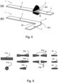
- Figure 7 shows an extruded profile 1 with a corresponding cross-sectional adjustment in the profile section 2 in different views (a), (b) and (c).
- the cross-sectional shape Q2 of the extruded profile 1 in the profile section 2 is trapezoidal and symmetrical to the designated bending plane B, so that it tapers continuously and linearly starting from the designated bending outside BA to the designated bending inside BI.
- the main axis of the cross-sectional shape Q2 of the extruded profile 1 in the profile section 2, ie the largest dimension of the cross-sectional shape Q2 of the extruded profile 1, runs in the bending plane B.
- the center of gravity F2 of the cross-sectional shape Q2 in the designated profile section 2 is relative to the profile axis A to the designated bending outside BA offset.
- the cross-sectional shape Q2 of the extruded profile 1 in the profile section 2 is not uniform along the profile axis A.
- the profile section 2 is arranged between two neighboring sections 3 which are adjacent along the profile axis A.
- the offset of the center of gravity F2 of the cross-sectional shape Q2 with respect to the profile axis A increases along the profile axis A starting from one of the adjacent neighboring sections 3, remains constant in a wedge-shaped middle section 2a and increases in a further oblique wedge section 2b the other of the adjacent neighboring sections 3 again.
- the surfaces of the wedge sections 2b and the middle section 2a preferably lie in planes that meet at an imaginary point.
- This imaginary point preferably corresponds to the later center of bending/curvature.
- the described cross-sectional shape Q2 of the extruded profile 1 in the profile section 2, which is particularly suitable for the (upright) bending of individual sheets alternating with straight neighboring sections 3, can be produced, for example, by applying material to the designated outside bending side BA and/or removing material from the designated inside bending side BI, for example, starting from an extruded profile 1 with a cross-sectional shape that is constant with respect to the profile axis A.
- the area of the cross-sectional shape Q2, Q2 'of the extruded profile 1 in the profile section 2, 2' reduces during bending, the dimension of the cross-sectional shape Q2, Q2' of the extruded profile 1 in the bending plane B between the outside bending side BA and the inside bending side BI remaining constant , while the dimension of the cross-sectional shape Q2 of the extruded profile 1 decreases perpendicular to the bending plane B.
- the cross-sectional shape Q2' of the extruded profile 1 in the profile section 2' is changed from trapezoidal to rectangular, so that the top and bottom sides of the cross-sectional shape Q2' after the bending deformation are exactly parallel to one another and, if necessary, exactly parallel to the bending plane B extend.
- the cross-sectional shape Q2' of the extruded profile 1 in the profile section 2 is adjusted to the cross-sectional shape Q3 of the extruded profile 1 in the adjacent neighboring sections 3, so that the cross-sectional shape Q2', Q3 of the extruded profile 1 after the bending deformation both in the profile section 2 and the adjacent neighboring sections 3 is rectangular and the main axis of the cross-sectional shape Q2 of the extruded profile 1 runs in the profile section 2 in the bending plane B.
- the bending center or the center of bending/curvature is very close to the inside of the bend BI ⁇ , with the bending radius in the profile section 2' being comparatively small and in the range of 50% to approx. 100% of the dimension of the cross-sectional shape Q2 ⁇ in the Bending plane B is located.
- the center of gravity F2 of the cross-sectional shape Q2 is shifted by the amount ⁇ FS in the direction of the profile axis A, so that the center of gravity F2' of the formed cross-sectional shape Q2' - as well as the center of gravity F3 of the cross-sectional shape Q3 in the neighboring sections 3 - after step B ideally coincides with the profile axis A.
- edge-bending electrically conductive extruded profiles for shaped coils is the achievement of the desired ideally rectangular cross-section and the associated high degree of filling as well as large-area contact for improved heat dissipation between the individual turns and the external environment. With the degree of filling and the improved heat dissipation, the achievable power density increases and the use of materials for the same performance is minimized.
- the extruded profile 1 can be produced entirely using the extrusion process with a constant cross-sectional shape along the profile axis A, as described below with reference to Figure 6 is explained. Since trapezoidal cross-sections are generally not easy to produce using the extrusion process, a double or multiple profile P2a, P2b is preferably first produced from a rectangular profile P1a, which has a cross-sectional shape corresponding to two mirror-symmetrical trapezoids, which are parallel along their shorter (P2a) or longer ones Pages (P2b) are connected to each other.
- This double or multiple profile P2a, P2b is subsequently separated along a plane of symmetry into two individual profiles P3a, P3b in order to have the cross-sectional shape specified in step A.
- the profile P4 of an upright winding ideally has a uniform cross-sectional shape along the profile axis and a uniform bending radius along the profile axis, so that the turns of the extruded profile 1 can contact each other flatly in the winding direction or perpendicular to the bending plane.
- the approach to producing forming strips for vertical winding is therefore to roll a single profile P3a, P3b after separating a double or even-numbered multiple profile P2a, P2b created from an initially rectangular extruded profile P1a in order to produce the profile P4 of an upright winding while avoiding curvature.
- the material structure in the bend can be analyzed and the processes used to produce this area can be demonstrated. If a bent round wire P1b, such as in Figure 6 shown, brought into the desired cross-section P2c by pressing, the orientation of the grains is different than if the extruded profile 1 is produced directly with a cross-section in which the center of gravity F2 of the cross-sectional shape Q2 in the profile section 2 with respect to the profile axis A to the designated bending outside BA is offset.
- the main areas of application of the invention are electrical machines (generators, motors, transformers) and components (coils, chokes). Furthermore, the invention can be used advantageously wherever flat profiles have to be bent around narrow radii and the usual change in the cross section leads to disadvantages.
- One such field of application is, for example, the winding of laminated cores of electrical machines from strips of electrical sheet metal. Due to the usual change in the cross-section, it becomes trapezoidal and is therefore unsuitable for stacking and also for baking the layers using thin layers.
Landscapes
- Engineering & Computer Science (AREA)
- Mechanical Engineering (AREA)
- Manufacture Of Motors, Generators (AREA)
- Bending Of Plates, Rods, And Pipes (AREA)
Claims (13)
- Procédé de cintrage de profilés extrudés (1), comprenant les étapes suivantes :a. étape A : fourniture d'un profilé extrudé (1) s'étendant le long d'un axe de profilé (A) avec au moins une section de profilé (2) dans laquelle le centre de gravité (F2) de la forme en section transversale (Q2) est décalé par rapport à l'axe de profilé (A) ;b. étape B : cintrage de ladite au moins une section de profilé (2'), de sorte que le centre de gravité (F2') de la forme en section transversale (Q2') est décalé dans la direction de l'axe de profilé (A) vers le côté intérieur du cintrage, qui fait face au centre de courbure du cintrage, et coïncide de préférence avec l'axe du profilé (A),caractérisé en ce que la section de profilé (2) est disposée entre deux sections voisines (3) qui sont adjacentes le long de l'axe de profilé (A), dans lequel, à l'étape B, la forme en section transversale (Q2) du profilé extrudé (1) dans la section de profilé (2) est adaptée exactement ou sensiblement à la forme en section transversale (Q3) du profilé extrudé (1) dans les sections voisines contiguës (3) .
- Procédé selon la revendication 1, caractérisé en ce que la forme en section transversale (Q2) du profilé extrudé (1) pourvu à l'étape A est conique dans la section de profilé (2), de préférence conique de manière continue et/ou linéaire, dans lequel, de manière particulièrement préférée, cette forme en section transversale (Q2) est symétrique et/ou trapézoïdale.
- Procédé selon l'une des revendications précédentes, caractérisé en ce que la surface de la forme en section transversale (Q2, Q2') du profilé extrudé (1) dans la section de profilé (2, 2') est réduite à l'étape B, dans lequel, de préférence, le rapport de la dimension de cette forme en section transversale (Q2, Q2') dans le plan de cintrage (B) par la dimension de cette forme en section transversale (Q2, Q2') perpendiculairement au plan de cintrage (B) augmente, dans lequel, de préférence, la dimension de cette forme en section transversale (Q2, Q2') reste constante dans le plan de cintrage (B) et/ou la dimension de cette forme en section transversale (Q2) diminue perpendiculairement au plan de cintrage (B), dans lequel, de manière particulièrement préférée, l'axe principal de cette forme en section transversale (Q2) s'étend dans le plan de cintrage (B) avant et/ou après le cintrage.
- Procédé selon l'une des revendications précédentes, caractérisé en ce que la forme en section transversale (Q2') du profilé extrudé (1) dans la section de profilé (2, 2') est modifiée à l'étape B de sorte qu'après l'étape B, deux de ses côtés sont exactement ou sensiblement parallèles entre eux et/ou exactement ou sensiblement parallèles au plan de cintrage (B), dans lequel, après l'étape B, cette forme en section transversale (Q2') est de préférence rectangulaire et/ou symétrique au plan de cintrage (B), dans lequel, avant et/ou après l'étape B, la dimension de cette forme en section transversale (Q2, Q2') dans le plan de cintrage (B) est de préférence supérieure à sa dimension perpendiculaire au plan de cintrage (B).
- Procédé selon l'une des revendications précédentes, caractérisé en ce que la forme en section transversale (Q2) du profilé extrudé (1) dans la section de profilé (2) est réalisée par application et/ou enlèvement de matière, de préférence à partir d'un profilé extrudé (1) ayant une forme en section transversale constante selon son axe de profilé (A) .
- Procédé selon l'une des revendications précédentes, caractérisé en ce que la forme en section transversale (Q3) du profilé extrudé (1) dans les sections voisines (3) contiguës à la section de profilé (2) est de préférence rectangulaire par rapport à l'axe de profilé (A) avant et/ou après l'étape B.
- Procédé selon l'une des revendications précédentes, caractérisé en ce que dans le profilé extrudé (1) pourvu à l'étape A, le décalage du centre de gravité (F2) de la forme en section transversale (Q2) par rapport à l'axe du profilé (A) le long de l'axe de profilé (A) entre les sections voisines (3) contiguës à la section de profilé (2) est uniforme sur toute la section de profilé (2) ou au moins une partie de la section de profilé (2), dans lequel le décalage augmente de préférence en partant de l'une des sections voisines contiguës (3) et diminue vers les autres dites sections voisines adjacentes (3).
- Procédé selon l'une des revendications précédentes, caractérisé en ce que le profilé extrudé (1) pourvu à l'étape A est de préférence produit par le procédé d'extrusion avec une forme en section transversale à symétrie axiale par rapport à deux plans perpendiculaires l'un à l'autre, de préférence sous la forme de deux trapèzes à symétrie axiale qui sont reliés l'un à l'autre le long de leurs côtés parallèles plus courts ou plus longs, dans lequel le profilé extrudé (1) est de préférence sectionné ensuite le long d'un plan de symétrie afin d'obtenir la forme en section transversale spécifiée à l'étape A dans au moins une section de profilé (2).
- Procédé selon l'une des revendications précédentes, caractérisé en ce que le rayon de courbure du centrage de la section de profilé (2) à l'étape B est compris dans une plage de 0 à 500 %, de préférence de 0 à 200 %, de préférence encore de 0 à 100 % de la dimension de la forme en section transversale dans le plan de cintrage (B).
- Procédé selon l'une des revendications précédentes, caractérisé en ce que le cintrage du profilé extrudé (1) dans la section de profilé (2) réalisé à l'étape B s'effectue par roulage.
- Procédé selon l'une des revendications précédentes, caractérisé en ce que l'axe de profilé (A) du profilé extrudé (1) forme une droite avant l'étape B et/ou un enroulement d'au moins un tour après l'étape B.
- Procédé selon l'une des revendications précédentes, caractérisé en ce qu'à l'étape B, la section de profilé (2) est cintrée vers le côté le plus court de sa forme en section transversale (Q2).
- Procédé de fabrication d'une bobine électrique par cintrage d'un profilé extrudé électroconducteur (1) selon le procédé de l'une des revendications précédentes, de sorte que le profilé extrudé (1) présente de préférence une forme en section transversale uniforme le long de l'axe du profilé (A) et/ou un rayon de courbure uniforme le long de l'axe du profilé (A) ou une alternance de sections droites et cintrées, dans lequel les enroulements du profilé extrudé (1) sont de préférence en contact plan sensiblement perpendiculairement au plan de cintrage.
Applications Claiming Priority (2)
| Application Number | Priority Date | Filing Date | Title |
|---|---|---|---|
| DE102016224837.5A DE102016224837A1 (de) | 2016-12-13 | 2016-12-13 | Verfahren zur Biegeumformung von Strangprofilen |
| PCT/EP2017/082648 WO2018109017A1 (fr) | 2016-12-13 | 2017-12-13 | Procédé de cintrage de profilés extrudés |
Publications (3)
| Publication Number | Publication Date |
|---|---|
| EP3554730A1 EP3554730A1 (fr) | 2019-10-23 |
| EP3554730B1 true EP3554730B1 (fr) | 2023-09-20 |
| EP3554730C0 EP3554730C0 (fr) | 2023-09-20 |
Family
ID=61027648
Family Applications (1)
| Application Number | Title | Priority Date | Filing Date |
|---|---|---|---|
| EP17835609.3A Active EP3554730B1 (fr) | 2016-12-13 | 2017-12-13 | Procédé de cintrage de profilés extrudés |
Country Status (3)
| Country | Link |
|---|---|
| EP (1) | EP3554730B1 (fr) |
| DE (1) | DE102016224837A1 (fr) |
| WO (1) | WO2018109017A1 (fr) |
Families Citing this family (3)
| Publication number | Priority date | Publication date | Assignee | Title |
|---|---|---|---|---|
| DE102017209792B4 (de) | 2017-06-09 | 2023-10-05 | Fraunhofer-Gesellschaft zur Förderung der angewandten Forschung e.V. | Halbzeug für eine elektrotechnische Spule sowie Verfahren und Vorrichtung zur Herstellung desselben |
| DE102020210862A1 (de) | 2020-08-28 | 2022-03-03 | Robert Bosch Gesellschaft mit beschränkter Haftung | Verfahren zur Herstellung eines Blechpakets für einen Rotor oder einen Stator |
| CN114850262B (zh) * | 2022-05-20 | 2024-10-01 | 浙江西子势必锐航空工业有限公司 | 一种l型截面铝型材辊弯系统及其辊弯工艺 |
Citations (1)
| Publication number | Priority date | Publication date | Assignee | Title |
|---|---|---|---|---|
| WO2016175179A1 (fr) * | 2015-04-27 | 2016-11-03 | 三菱重工業株式会社 | Dispositif de laminage, procédé de cintrage et matériau de cintrage |
Family Cites Families (13)
| Publication number | Priority date | Publication date | Assignee | Title |
|---|---|---|---|---|
| AT192729B (de) * | 1955-01-12 | 1957-10-25 | Elin Ag Elek Ind Wien | Verfahren und Vorrichtung zur Herstellung von flachen, ebenen Ringen oder Bogenstücken |
| DE1037574B (de) | 1955-09-12 | 1958-08-28 | Westinghouse Electric Corp | Blechpaket, insbesondere fuer Staender kleiner Elektromotoren, dessen Lamellen aus einem hochkant gewundenen Blechstreifen bestehen |
| US2845555A (en) | 1955-09-12 | 1958-07-29 | Westinghouse Electric Corp | Motors |
| CH494604A (de) * | 1968-08-10 | 1970-08-15 | Haeusler Christian | Rundmaschine zur Herstellung eines Konus aus einem kreisringsegmentförmigen Blech |
| US3708706A (en) | 1970-10-13 | 1973-01-02 | Tokyo Shibaura Electric Co | Magnetic core elements for rotating electrical machines |
| JPS53801A (en) * | 1976-06-25 | 1978-01-07 | Hitachi Ltd | Manufacturing method of wound stator core |
| DE2705206A1 (de) | 1977-02-08 | 1978-08-10 | Novikov | Verfahren zur herstellung von bandmagnetkoerpern fuer elektrische maschinen |
| US4322879A (en) * | 1978-02-13 | 1982-04-06 | Warchol Henry A | Bearing components and methods of making same |
| JPH1119745A (ja) * | 1997-06-30 | 1999-01-26 | Aisin Seiki Co Ltd | リング製造方法およびリング製造装置 |
| DE10358693A1 (de) | 2003-12-15 | 2005-07-14 | Siemens Ag | Elektrische Maschine |
| DE102004003681A1 (de) * | 2004-01-24 | 2005-08-11 | Klingelnberg Ag | Biegevorrichtung mit Pendelwalzrollen |
| JP4831125B2 (ja) | 2008-05-21 | 2011-12-07 | トヨタ自動車株式会社 | 巻線方法、巻線装置、及び固定子 |
| KR20120130324A (ko) * | 2010-02-01 | 2012-11-30 | 더 팀켄 컴퍼니 | 롤러 베어링 케이지를 위한 통합된 롤링 및 벤딩 공정 |
-
2016
- 2016-12-13 DE DE102016224837.5A patent/DE102016224837A1/de not_active Withdrawn
-
2017
- 2017-12-13 EP EP17835609.3A patent/EP3554730B1/fr active Active
- 2017-12-13 WO PCT/EP2017/082648 patent/WO2018109017A1/fr not_active Ceased
Patent Citations (1)
| Publication number | Priority date | Publication date | Assignee | Title |
|---|---|---|---|---|
| WO2016175179A1 (fr) * | 2015-04-27 | 2016-11-03 | 三菱重工業株式会社 | Dispositif de laminage, procédé de cintrage et matériau de cintrage |
Also Published As
| Publication number | Publication date |
|---|---|
| DE102016224837A1 (de) | 2018-06-14 |
| EP3554730C0 (fr) | 2023-09-20 |
| EP3554730A1 (fr) | 2019-10-23 |
| WO2018109017A1 (fr) | 2018-06-21 |
Similar Documents
| Publication | Publication Date | Title |
|---|---|---|
| DE102013212087B4 (de) | Verfahren zur Herstellung einer Spule | |
| DE102013012659B4 (de) | Verfahren und Prägewerkzeug zur Herstellung einer elektrotechnischen Spule | |
| DE102011081030A1 (de) | Wicklungsträger zur Verwendung in einer elektrischen Maschine sowie Wicklungsanordnung | |
| DE112013004716T5 (de) | Verfahren zum Herstellen einer Ankerwicklung für eine elektrische Maschine | |
| WO2012072757A2 (fr) | Procédé de fabrication d'un enroulement de stator d'un moteur électrique, notamment d'un générateur de courant alternatif | |
| WO2010136603A2 (fr) | Procédé pour produire un enroulement de stator d'une machine électrique, notamment pour produire un alternateur | |
| DE102008057390A1 (de) | Segmentierte Stator-/Rotorelemente von Elektromotoren | |
| DE112015000717T5 (de) | Rotierende elektrische Maschine und Verfahren zum Herstellen einer Spule für eine rotierende elektrische Maschine | |
| EP4275265A1 (fr) | Procédé pour fabriquer un stator ainsi que stator | |
| DE102012010226B4 (de) | Verfahren zur Herstellung einer elektrotechnischen Spule sowie elektrotechnische Spule undElektromaschine mit einer solchen | |
| WO2018109017A1 (fr) | Procédé de cintrage de profilés extrudés | |
| DE102024115404A1 (de) | Wicklung für einen Stator für eine elektrische Maschine mit ersten und zweiten Leitervorrichtungen | |
| DE102018206003A1 (de) | Vorrichtung und Verfahren zur Ausrichtung einer Hairpinwicklung | |
| EP3981062B1 (fr) | Procédé de fabrication d'un enroulement statorique et machine électrique | |
| DE202012104118U1 (de) | Gezogener Draht mit Isolierung | |
| EP4393048A1 (fr) | Procédé de fabrication d'un enroulement de bobine | |
| EP1825589B1 (fr) | Système de fabrication et procédé de production d'un élément electromagnétique pour machine électrique | |
| WO2024125694A1 (fr) | Procédé de remise en forme et d'introduction d'un enroulement dans un corps de rotor ou dans un corps de stator | |
| DE102018208410A1 (de) | Kurzschlussläufer für einen Elektromotor, insbesondere einen Asynchronmotor, Elektromotor, sowie Verfahren zur Herstellung eines Kurzschlussläufers | |
| EP4342672A1 (fr) | Tôle magnétique fabriquée de manière additive, paquet de tôles et machine électrique | |
| EP3429063A1 (fr) | Enroulement monocouche de support pour des machines électriques | |
| EP0932241B1 (fr) | Procédé de fabrication de barres conductrices | |
| DE2656277A1 (de) | Verfahren und vorrichtung zum herstellen von betonbewehrungsstaeben | |
| DE102017213106B4 (de) | Verfahren zur Herstellung einer elektrotechnischen Spule | |
| EP4704246A1 (fr) | Outil de formage d'une préforme en une ébauche de barre conductrice et dispositif de formage doté d'un tel outil |
Legal Events
| Date | Code | Title | Description |
|---|---|---|---|
| STAA | Information on the status of an ep patent application or granted ep patent |
Free format text: STATUS: UNKNOWN |
|
| STAA | Information on the status of an ep patent application or granted ep patent |
Free format text: STATUS: THE INTERNATIONAL PUBLICATION HAS BEEN MADE |
|
| PUAI | Public reference made under article 153(3) epc to a published international application that has entered the european phase |
Free format text: ORIGINAL CODE: 0009012 |
|
| STAA | Information on the status of an ep patent application or granted ep patent |
Free format text: STATUS: REQUEST FOR EXAMINATION WAS MADE |
|
| 17P | Request for examination filed |
Effective date: 20190517 |
|
| AK | Designated contracting states |
Kind code of ref document: A1 Designated state(s): AL AT BE BG CH CY CZ DE DK EE ES FI FR GB GR HR HU IE IS IT LI LT LU LV MC MK MT NL NO PL PT RO RS SE SI SK SM TR |
|
| AX | Request for extension of the european patent |
Extension state: BA ME |
|
| DAV | Request for validation of the european patent (deleted) | ||
| DAX | Request for extension of the european patent (deleted) | ||
| STAA | Information on the status of an ep patent application or granted ep patent |
Free format text: STATUS: EXAMINATION IS IN PROGRESS |
|
| 17Q | First examination report despatched |
Effective date: 20210906 |
|
| RAP3 | Party data changed (applicant data changed or rights of an application transferred) |
Owner name: FRAUNHOFER-GESELLSCHAFT ZUR FOERDERUNG DER ANGEWANDTEN FORSCHUNG E.V. |
|
| GRAP | Despatch of communication of intention to grant a patent |
Free format text: ORIGINAL CODE: EPIDOSNIGR1 |
|
| STAA | Information on the status of an ep patent application or granted ep patent |
Free format text: STATUS: GRANT OF PATENT IS INTENDED |
|
| INTG | Intention to grant announced |
Effective date: 20230412 |
|
| GRAS | Grant fee paid |
Free format text: ORIGINAL CODE: EPIDOSNIGR3 |
|
| GRAA | (expected) grant |
Free format text: ORIGINAL CODE: 0009210 |
|
| STAA | Information on the status of an ep patent application or granted ep patent |
Free format text: STATUS: THE PATENT HAS BEEN GRANTED |
|
| AK | Designated contracting states |
Kind code of ref document: B1 Designated state(s): AL AT BE BG CH CY CZ DE DK EE ES FI FR GB GR HR HU IE IS IT LI LT LU LV MC MK MT NL NO PL PT RO RS SE SI SK SM TR |
|
| REG | Reference to a national code |
Ref country code: GB Ref legal event code: FG4D Free format text: NOT ENGLISH |
|
| REG | Reference to a national code |
Ref country code: CH Ref legal event code: EP |
|
| REG | Reference to a national code |
Ref country code: IE Ref legal event code: FG4D Free format text: LANGUAGE OF EP DOCUMENT: GERMAN |
|
| REG | Reference to a national code |
Ref country code: DE Ref legal event code: R096 Ref document number: 502017015410 Country of ref document: DE |
|
| U01 | Request for unitary effect filed |
Effective date: 20230922 |
|
| U07 | Unitary effect registered |
Designated state(s): AT BE BG DE DK EE FI FR IT LT LU LV MT NL PT SE SI Effective date: 20230927 |
|
| U20 | Renewal fee for the european patent with unitary effect paid |
Year of fee payment: 7 Effective date: 20231214 |
|
| PG25 | Lapsed in a contracting state [announced via postgrant information from national office to epo] |
Ref country code: GR Free format text: LAPSE BECAUSE OF FAILURE TO SUBMIT A TRANSLATION OF THE DESCRIPTION OR TO PAY THE FEE WITHIN THE PRESCRIBED TIME-LIMIT Effective date: 20231221 |
|
| PG25 | Lapsed in a contracting state [announced via postgrant information from national office to epo] |
Ref country code: RS Free format text: LAPSE BECAUSE OF FAILURE TO SUBMIT A TRANSLATION OF THE DESCRIPTION OR TO PAY THE FEE WITHIN THE PRESCRIBED TIME-LIMIT Effective date: 20230920 Ref country code: NO Free format text: LAPSE BECAUSE OF FAILURE TO SUBMIT A TRANSLATION OF THE DESCRIPTION OR TO PAY THE FEE WITHIN THE PRESCRIBED TIME-LIMIT Effective date: 20231220 Ref country code: HR Free format text: LAPSE BECAUSE OF FAILURE TO SUBMIT A TRANSLATION OF THE DESCRIPTION OR TO PAY THE FEE WITHIN THE PRESCRIBED TIME-LIMIT Effective date: 20230920 Ref country code: GR Free format text: LAPSE BECAUSE OF FAILURE TO SUBMIT A TRANSLATION OF THE DESCRIPTION OR TO PAY THE FEE WITHIN THE PRESCRIBED TIME-LIMIT Effective date: 20231221 |
|
| PG25 | Lapsed in a contracting state [announced via postgrant information from national office to epo] |
Ref country code: IS Free format text: LAPSE BECAUSE OF FAILURE TO SUBMIT A TRANSLATION OF THE DESCRIPTION OR TO PAY THE FEE WITHIN THE PRESCRIBED TIME-LIMIT Effective date: 20240120 |
|
| PG25 | Lapsed in a contracting state [announced via postgrant information from national office to epo] |
Ref country code: ES Free format text: LAPSE BECAUSE OF FAILURE TO SUBMIT A TRANSLATION OF THE DESCRIPTION OR TO PAY THE FEE WITHIN THE PRESCRIBED TIME-LIMIT Effective date: 20230920 |
|
| PG25 | Lapsed in a contracting state [announced via postgrant information from national office to epo] |
Ref country code: SM Free format text: LAPSE BECAUSE OF FAILURE TO SUBMIT A TRANSLATION OF THE DESCRIPTION OR TO PAY THE FEE WITHIN THE PRESCRIBED TIME-LIMIT Effective date: 20230920 Ref country code: RO Free format text: LAPSE BECAUSE OF FAILURE TO SUBMIT A TRANSLATION OF THE DESCRIPTION OR TO PAY THE FEE WITHIN THE PRESCRIBED TIME-LIMIT Effective date: 20230920 Ref country code: IS Free format text: LAPSE BECAUSE OF FAILURE TO SUBMIT A TRANSLATION OF THE DESCRIPTION OR TO PAY THE FEE WITHIN THE PRESCRIBED TIME-LIMIT Effective date: 20240120 Ref country code: ES Free format text: LAPSE BECAUSE OF FAILURE TO SUBMIT A TRANSLATION OF THE DESCRIPTION OR TO PAY THE FEE WITHIN THE PRESCRIBED TIME-LIMIT Effective date: 20230920 Ref country code: CZ Free format text: LAPSE BECAUSE OF FAILURE TO SUBMIT A TRANSLATION OF THE DESCRIPTION OR TO PAY THE FEE WITHIN THE PRESCRIBED TIME-LIMIT Effective date: 20230920 Ref country code: SK Free format text: LAPSE BECAUSE OF FAILURE TO SUBMIT A TRANSLATION OF THE DESCRIPTION OR TO PAY THE FEE WITHIN THE PRESCRIBED TIME-LIMIT Effective date: 20230920 |
|
| PG25 | Lapsed in a contracting state [announced via postgrant information from national office to epo] |
Ref country code: PL Free format text: LAPSE BECAUSE OF FAILURE TO SUBMIT A TRANSLATION OF THE DESCRIPTION OR TO PAY THE FEE WITHIN THE PRESCRIBED TIME-LIMIT Effective date: 20230920 |
|
| REG | Reference to a national code |
Ref country code: DE Ref legal event code: R097 Ref document number: 502017015410 Country of ref document: DE |
|
| PLBE | No opposition filed within time limit |
Free format text: ORIGINAL CODE: 0009261 |
|
| STAA | Information on the status of an ep patent application or granted ep patent |
Free format text: STATUS: NO OPPOSITION FILED WITHIN TIME LIMIT |
|
| REG | Reference to a national code |
Ref country code: CH Ref legal event code: PL |
|
| PG25 | Lapsed in a contracting state [announced via postgrant information from national office to epo] |
Ref country code: MC Free format text: LAPSE BECAUSE OF FAILURE TO SUBMIT A TRANSLATION OF THE DESCRIPTION OR TO PAY THE FEE WITHIN THE PRESCRIBED TIME-LIMIT Effective date: 20230920 |
|
| 26N | No opposition filed |
Effective date: 20240621 |
|
| GBPC | Gb: european patent ceased through non-payment of renewal fee |
Effective date: 20231220 |
|
| PG25 | Lapsed in a contracting state [announced via postgrant information from national office to epo] |
Ref country code: MC Free format text: LAPSE BECAUSE OF FAILURE TO SUBMIT A TRANSLATION OF THE DESCRIPTION OR TO PAY THE FEE WITHIN THE PRESCRIBED TIME-LIMIT Effective date: 20230920 |
|
| REG | Reference to a national code |
Ref country code: IE Ref legal event code: MM4A |
|
| PG25 | Lapsed in a contracting state [announced via postgrant information from national office to epo] |
Ref country code: IE Free format text: LAPSE BECAUSE OF NON-PAYMENT OF DUE FEES Effective date: 20231213 |
|
| PG25 | Lapsed in a contracting state [announced via postgrant information from national office to epo] |
Ref country code: GB Free format text: LAPSE BECAUSE OF NON-PAYMENT OF DUE FEES Effective date: 20231220 |
|
| PG25 | Lapsed in a contracting state [announced via postgrant information from national office to epo] |
Ref country code: CH Free format text: LAPSE BECAUSE OF NON-PAYMENT OF DUE FEES Effective date: 20231231 |
|
| PG25 | Lapsed in a contracting state [announced via postgrant information from national office to epo] |
Ref country code: IE Free format text: LAPSE BECAUSE OF NON-PAYMENT OF DUE FEES Effective date: 20231213 Ref country code: GB Free format text: LAPSE BECAUSE OF NON-PAYMENT OF DUE FEES Effective date: 20231220 Ref country code: CH Free format text: LAPSE BECAUSE OF NON-PAYMENT OF DUE FEES Effective date: 20231231 |
|
| U20 | Renewal fee for the european patent with unitary effect paid |
Year of fee payment: 8 Effective date: 20241219 |
|
| PG25 | Lapsed in a contracting state [announced via postgrant information from national office to epo] |
Ref country code: CY Free format text: LAPSE BECAUSE OF FAILURE TO SUBMIT A TRANSLATION OF THE DESCRIPTION OR TO PAY THE FEE WITHIN THE PRESCRIBED TIME-LIMIT; INVALID AB INITIO Effective date: 20171213 |
|
| PG25 | Lapsed in a contracting state [announced via postgrant information from national office to epo] |
Ref country code: HU Free format text: LAPSE BECAUSE OF FAILURE TO SUBMIT A TRANSLATION OF THE DESCRIPTION OR TO PAY THE FEE WITHIN THE PRESCRIBED TIME-LIMIT; INVALID AB INITIO Effective date: 20171213 |
|
| PG25 | Lapsed in a contracting state [announced via postgrant information from national office to epo] |
Ref country code: TR Free format text: LAPSE BECAUSE OF FAILURE TO SUBMIT A TRANSLATION OF THE DESCRIPTION OR TO PAY THE FEE WITHIN THE PRESCRIBED TIME-LIMIT Effective date: 20230920 |