EP3554761B1 - Verfahren, überwachungsknoten und computerprogramm zur überwachung des energieflusses in einem spannwerkzeug - Google Patents
Verfahren, überwachungsknoten und computerprogramm zur überwachung des energieflusses in einem spannwerkzeug Download PDFInfo
- Publication number
- EP3554761B1 EP3554761B1 EP17808465.3A EP17808465A EP3554761B1 EP 3554761 B1 EP3554761 B1 EP 3554761B1 EP 17808465 A EP17808465 A EP 17808465A EP 3554761 B1 EP3554761 B1 EP 3554761B1
- Authority
- EP
- European Patent Office
- Prior art keywords
- tightening tool
- tightening
- tool
- joint
- torque
- Prior art date
- Legal status (The legal status is an assumption and is not a legal conclusion. Google has not performed a legal analysis and makes no representation as to the accuracy of the status listed.)
- Active
Links
Images


Classifications
-
- B—PERFORMING OPERATIONS; TRANSPORTING
- B25—HAND TOOLS; PORTABLE POWER-DRIVEN TOOLS; MANIPULATORS
- B25B—TOOLS OR BENCH DEVICES NOT OTHERWISE PROVIDED FOR, FOR FASTENING, CONNECTING, DISENGAGING, OR HOLDING
- B25B23/00—Details of, or accessories for, spanners, wrenches, screwdrivers
- B25B23/14—Arrangement of torque limiters or torque indicators in wrenches or screwdrivers
- B25B23/142—Arrangement of torque limiters or torque indicators in wrenches or screwdrivers specially adapted for hand operated wrenches or screwdrivers
- B25B23/1422—Arrangement of torque limiters or torque indicators in wrenches or screwdrivers specially adapted for hand operated wrenches or screwdrivers torque indicators or adjustable torque limiters
- B25B23/1425—Arrangement of torque limiters or torque indicators in wrenches or screwdrivers specially adapted for hand operated wrenches or screwdrivers torque indicators or adjustable torque limiters by electrical means
-
- B—PERFORMING OPERATIONS; TRANSPORTING
- B25—HAND TOOLS; PORTABLE POWER-DRIVEN TOOLS; MANIPULATORS
- B25B—TOOLS OR BENCH DEVICES NOT OTHERWISE PROVIDED FOR, FOR FASTENING, CONNECTING, DISENGAGING, OR HOLDING
- B25B21/00—Portable power-driven screw or nut setting or loosening tools; Attachments for drilling apparatus serving the same purpose
- B25B21/008—Portable power-driven screw or nut setting or loosening tools; Attachments for drilling apparatus serving the same purpose with automatic change-over from high speed-low torque mode to low speed-high torque mode
-
- B—PERFORMING OPERATIONS; TRANSPORTING
- B25—HAND TOOLS; PORTABLE POWER-DRIVEN TOOLS; MANIPULATORS
- B25B—TOOLS OR BENCH DEVICES NOT OTHERWISE PROVIDED FOR, FOR FASTENING, CONNECTING, DISENGAGING, OR HOLDING
- B25B23/00—Details of, or accessories for, spanners, wrenches, screwdrivers
- B25B23/14—Arrangement of torque limiters or torque indicators in wrenches or screwdrivers
- B25B23/147—Arrangement of torque limiters or torque indicators in wrenches or screwdrivers specially adapted for electrically operated wrenches or screwdrivers
-
- G—PHYSICS
- G05—CONTROLLING; REGULATING
- G05B—CONTROL OR REGULATING SYSTEMS IN GENERAL; FUNCTIONAL ELEMENTS OF SUCH SYSTEMS; MONITORING OR TESTING ARRANGEMENTS FOR SUCH SYSTEMS OR ELEMENTS
- G05B19/00—Program-control systems
- G05B19/02—Program-control systems electric
- G05B19/18—Numerical control [NC], i.e. automatically operating machines, in particular machine tools, e.g. in a manufacturing environment, so as to execute positioning, movement or co-ordinated operations by means of program data in numerical form
- G05B19/406—Numerical control [NC], i.e. automatically operating machines, in particular machine tools, e.g. in a manufacturing environment, so as to execute positioning, movement or co-ordinated operations by means of program data in numerical form characterised by monitoring or safety
-
- G—PHYSICS
- G05—CONTROLLING; REGULATING
- G05B—CONTROL OR REGULATING SYSTEMS IN GENERAL; FUNCTIONAL ELEMENTS OF SUCH SYSTEMS; MONITORING OR TESTING ARRANGEMENTS FOR SUCH SYSTEMS OR ELEMENTS
- G05B23/00—Testing or monitoring of control systems or parts thereof
- G05B23/02—Electric testing or monitoring
- G05B23/0205—Electric testing or monitoring by means of a monitoring system capable of detecting and responding to faults
- G05B23/0259—Electric testing or monitoring by means of a monitoring system capable of detecting and responding to faults characterized by the response to fault detection
- G05B23/0267—Fault communication, e.g. human machine interface [HMI]
- G05B23/027—Alarm generation, e.g. communication protocol; Forms of alarm
-
- G—PHYSICS
- G08—SIGNALLING
- G08B—SIGNALLING SYSTEMS, e.g. PERSONAL CALLING SYSTEMS; ORDER TELEGRAPHS; ALARM SYSTEMS
- G08B21/00—Alarms responsive to a single specified undesired or abnormal condition and not otherwise provided for
- G08B21/18—Status alarms
- G08B21/182—Level alarms, e.g. alarms responsive to variables exceeding a threshold
Definitions
- the present invention relates generally to a method, a monitoring node and a computer program of monitoring energy flow in a tightening tool.
- Tightening tools and systems with tightening tools including portable tightening tools such as power wrenches operated by an operator, are often used in production work.
- a common application is in assembly lines.
- tightening tools in assembly lines may have a controller connected to them and the controller controls the work performed by the tool so that the tool works automatically. With other words the controller sees to that the tool is operated correctly, e.g. performing a wrench operation with the correct torque etc.
- the tools may have to perform new operations, change dimensions or torque or just adjust the current operation for a better performance.
- WO2016001210 there is disclosed a tool communications network for enabling remote control of tightening tools.
- This tool communications network is very useful for performing updates to many tool controllers at the same time, minimizing the time of an operator during the update.
- the mentioned tool communication network may also be used by the tool controllers to collect data of the result of work performed by the tightening tools, such as collecting the torque used for tightening a bolt or nut. Collecting such data is valuable for increasing traceability of products produced in an assembly line.
- the tool communication network has greatly improved the efficiency and quality of work at assembly lines.
- Document US2015247745 discloses a similar system and method for interaction with smart tools.
- Such improvement areas may be to foresee or detect impending tool failure, detect variations in material of the product assembled at the assembly line and operator behavior at a manufacturing station of the assembly line.
- a production technician may through experience know what station in the assembly line that usually has problems with tool usage or with operator behavior. This experience may be gained by observing the operators and/or looking at error codes displayed by the tightening system and other equipment. Observing operator behavior and error codes to gain an overview of the assembly line requires a lot of experience and also time from the production technician. Since the production technician only can be at one place at a time it will not only be difficult, but impossible, to observe the whole assembly line at once. This will lead to disturbances in the production, since there will be failures due to defective tightening tools, wrong operator behavior or material deficiencies.
- a method is provided performed by a monitoring node that is associated with a tool communication network to which also the tightening tool is connected.
- the method comprises receiving, from the tightening tool, parameter values relating to current fed into the tightening tool, angle of a rotor in the tightening tool and torque applied to a joint by the tightening tool, calculating the energy put into to the tightening tool based on the received parameter values relating to the current fed into the tightening tool and the angle of the rotor in the tightening tool, and calculating the energy transferred to the joint by the tightening tool based on the received parameter values relating to the torque applied to the joint by the tightening tool and the angle of the rotor in the tightening tool.
- the method furthermore comprises detecting that the calculated energy put into to the tightening tool deviates from the calculated energy transferred to the joint by the tightening tool with more than a predetermined value.
- the method also comprises transmitting an alarm message in response to detecting that the calculated energy put into to the tightening tool deviates from the calculated energy transferred to the joint by the tightening tool with more than a predetermined value.
- the method comprises sending a request for parameter values to the tightening tool, via the communication network.
- the receiving step of the method further comprises receiving, from the tightening tool, a parameter value relating to a temperature of the tightening tool, and calculating the predetermined value such that it correlates with the parameter value relating to the temperature of the tightening tool, i.e. increasing temperature leads to increasing predetermined value.
- the receiving step of the method comprises receiving, from a second tightening tool connected to the communication network, a parameter value relating to a temperature of the second tightening tool
- the detecting step further comprises detecting that the parameter value relating to the temperature of the tightening tool deviates with more than a predetermined temperature range from the parameter value relating to the temperature of the second tightening tool and wherein transmitting the alarm message comprises transmitting information about the deviation in the parameter values relating to the temperatures of the tightening tool and the second tightening tool.
- the method comprises retrieving, a parameter value relating to desired tightening torque for tightening the joint, and detecting that the retrieved parameter value relating to the desired tightening torque deviates from the received parameter value for the torque applied to the joint by the tightening tool and wherein transmitting the alarm message comprises transmitting information that the desired tightening torque deviates from the received parameter value for the torque applied to the joint by the tightening tool.
- a monitoring node for monitoring energy flow in a tightening tool and associated with a tool communication network.
- the tightening tool is also connected to the communications network.
- the monitoring node comprises a processor and a memory, the memory comprising instructions which when executed by the processor causes the monitoring node to receive, from the tightening tool, parameter values relating to current fed into the tightening tool, angle of a rotor in the tightening tool and torque applied to a joint by the tightening, calculate the energy put into to the tightening tool based on the received parameter values relating to the current fed into the tightening tool and the angle of the rotor in the tightening tool and calculate the energy transferred to the joint by the tightening tool based on the received parameter values relating to the torque applied to the joint by the tightening tool and the angle of the rotor in the tightening tool.
- the monitoring node is further caused to detect that the calculated energy put into to the tightening tool deviates from the calculated energy transferred to the joint by the tighten
- the monitoring node is further caused to transmit an alarm message in response to detecting that the calculated energy put into the tightening tool deviates from the calculated energy transferred to the joint by the tightening tool with more than a predetermined value.
- the monitoring node is, in another embodiment, caused to send a request for parameter values to the tightening tool, via the communication network.
- the monitoring node is further caused to receive, from the tightening tool, a parameter value relating to a temperature of the tightening tool and calculate the predetermined value such that it correlates with the parameter value relating to the temperature of the tightening tool, i.e. increasing temperature leads to increasing predetermined value.
- the monitoring node is further caused to receive, from a second tightening tool connected to the communication network, a parameter value relating to a temperature of the second tightening tool, detect that the parameter value relating to the temperature of the tightening tool deviates with more than a predetermined temperature range from the parameter value relating to the temperature of the second tightening tool and wherein transmitting the alarm message comprises transmitting information about the deviation in the parameter values relating to the temperatures of the tightening tool and the second tightening tool.
- the monitoring node is further caused to retrieve a parameter value relating to desired tightening torque for tightening the joint, detect that the received parameter value relating to the desired tightening torque deviates from the received parameter value for the torque applied to the joint by the tightening tool and wherein transmitting the alarm message comprises transmitting information that the desired tightening torque is smaller than the received parameter value for the torque applied to the joint by the tightening tool.
- a computer program and a computer program product comprises computer readable code is provided, which when executed on a processor of the monitoring node causes the monitoring node to behave as a monitoring node described in previous sections.
- a solution is provided to enable monitoring energy flow in a tightening tool in order to foresee or detect impending tool failure, detect variations in material of the product assembled at the assembly line and operator behavior at a manufacturing station of the assembly line.
- the tightening tools may be configurable for different operations.
- a specific tightening tool may further be a part of a manufacturing station together with material for production, arrangements for material handling, different accessories or fittings for the tightening tool, and so forth.
- the tightening tool is part of a tool communication network.
- the tool communications network may be operated in a small manufacturing plant in a clean environment.
- the tool communications network may be operated in a manufacturing environment distributed over several buildings or remote locations.
- the tool communications network may be operated in a manufacturing environment in a factory with a challenging environment of dirt, aggressive chemicals, electrical disturbances, sometimes challenging for communication equipment and computers.
- a suitable tool communications network for use together with the present invention is described in greater detail in WO2016001210 .
- Fig. 1 shows an overview of the tool communications network 50.
- the tool communications network 50 may comprise tightening tools 125, 135 (or other power tools), tool controllers 122, 123, a tool server 140, a communication node (hub) 150 and a monitoring node 100.
- the tool communication network 50 is set up to support different manufacturing stations 120, 130 that are part of an assembly line. Usually there are more than two manufacturing stations in an assembly line, but in Fig. 1 only two are shown in order to illustrate an explanatory tool communications network 50.
- Fig. 1 also shows a workpiece 110 having a first joint 80 (a bolt in Fig. 1 ) that is to be tighten at a first manufacturing station 120 and a second joint 90 to be tighten at a second manufacturing station 130.
- the tightening tools 125, 135 are connected with a respective tool controller 122, 123 for control, supervision and collection of result data from the tightening tools 125, 135.
- the tightening tools 125, 135 may be set up for simple operations such as tightening bolts as mentioned above. However, the tightening tools 125, 135 may also be set up for more complex work operations including a number of similar and different operations, series of operations with one equipment, shifting to another equipment followed by another series of operations and may be shifting to a third equipment. How the tightening tools 125, 135 should perform operations and interact with an operator may be based on control data received from the tool controllers 122, 123. Each individual operation may need to be performed with high accuracy in terms of e.g. torque and rotation speed. In order to maintain desirable quality control all results may be collected by sensors, such as the number of rotations, final torque, location of operation, time, and similar result data for tightening tool operation.
- the tool controllers 122, 123 controlling the tightening tools 125, 135 and accessory equipment have the primary task to control the tightening tools 125, 135.
- the tool controllers 122, 123 also manage configuration data and collect sensor data and store the sensor data as results of performed work operations.
- the tool controller 122, 123 may be a specific node for control of tightening tools 125, 135 or it may be for example a general purpose computer, which has been adapted for control of tightening tools.
- the tool controllers 122, 123 may be connected to the tool communication network 50 by wire as the tool controller 122 or wirelessly as schematically shown by tool controller 123.
- the tool controllers 122, 123 may also be termed controller, controller node, controlling node, control unit, tool processor, tool regulator, or similar terms.
- the tool controller 122, 123 may be co-located or comprised by a tightening tool 125, 135, a tool server 140, communication node 150, or other suitable technical nodes operating in a tool communications network 50.
- the tool server 140 is a server to which production managers or production technicians may connect for creation and/or administration of work operations for the tightening tools 125, 135.
- the tool server 140 may be a general purpose server or a tool server 140 specifically arranged for remote control of tightening tools 125, 135. Administrators connecting to the tool server may for example create, specify and change how a particular tightening tool or a group of tightening tools 125, 135 should behave in certain situations. Examples are series of operations, tool selections, values for each operation like a torque rate, number of rotations, rotational speed, position and how to end when result data should be feed backed to a tool server 140, etc.
- a communication node or hub 150 may be managing communication between different participating functional nodes or devices in the communications network 50.
- the communication node 150 may for example keep track of identities of tool controllers 122, tool servers 140, or tightening tools 125, 135.
- the communication node 150 may keep track of any nodes or devices alternating between "on line” and "off line".
- a tool controller 122 may for example not always be connected to a network for various reasons.
- the communication node 150 may further validate and/or authorize nodes or devices communicating in the communications network 50, such that only authorized nodes have the right to communicate with each other.
- the monitoring node 100 which is configured to monitor energy flow in the tightening tools 125, 135 may be part of the tool server 140, be provided as part of a cloud solution or be provided as a stand-alone server.
- the monitoring node 100 will be closer described in conjunction with Fig. 4 .
- the monitoring node 100 is associated with the tool communication network 50 for monitoring the energy flow in the tightening tools 125, 135 in for example an assembly line. As mentioned above the tightening tools 125, 135 are also connected to the communications network 50.
- the monitoring node 100 receives, from the tightening tool 125, parameter values relating to current fed into the tightening tool 125, angle of a rotor in the tightening tool 125 and torque applied to a joint 80 by the tightening tool 125.
- the tightening tools 125, 135 are provided with different types of sensors with help of which the fed current, the rotor angle and applied torque may be directly or indirectly obtained. There are many possible sensors that may be used to obtain parameter values that are associated with the received parameter values. What is important in the context of the present invention is that the monitoring node 100 receives parameter values that are associated with the fed current, the rotor angle and applied torque.
- the monitoring node calculates the energy put into to the tightening tool 125, 135 based on the received parameter values relating to the current fed into the tightening tool 125, 135 and the angle ⁇ of the rotor in the tightening tool.
- the monitoring node 100 also calculates the energy transferred to the joint 80 by the tightening tool 125, 135 based on the received parameter values relating to the torque applied to the joint 80 by the tightening tool 125, 135 and the angle ⁇ of the rotor in the tightening tool 125, 135.
- the monitoring node 100 detects that the calculated energy put into to the tightening tool 125, 135 deviates from the calculated energy transferred to the joint 80 by the tightening tool 125, 135 with more than a predetermined value.
- the energy put into the tightening tool may be 10 kWh and the energy transferred to the joint 80 may be 8 kWh. In this case we have a deviation of 2 kWh or 20%.
- the predetermined value is higher than 2 kWh or 20% the monitoring node 100 will detect the that the calculated energy put into to the tightening tool 125, 135 deviates from the calculated energy transferred to the joint 80 by the tightening tool 125, 135 with more than the predetermined value, i.e.
- the predetermined value may be an arbitrary value that is set by a production technician or the like. It should be noted that the energy values mention above only are used to illustrate an example and will depend on the type of tightening tool 125, 135 that is used.
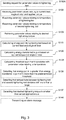
- FIG. 3 With reference to Fig. 3 different embodiments and variations of the method performed by the monitoring node 100 will be will be closer described.
- the main steps described in conjunction with Fig. 2 are repeated in Fig. 3 and are shown with unbroken lines.
- Optional steps and variations are shown with dashed lines in Fig. 3 .
- the monitoring node 100 transmits, in step S140, an alarm message in response to detecting that the calculated energy put into to the tightening tool 125, 135 deviates from the calculated energy transferred to the joint 80 by the tightening tool 125, 135 with more than the predetermined value as mentioned above.
- This alarm message may be sent to the tool server 140 for storage and later access by the production manager or any other authorized person.
- the alarm message may also be sent to any other node in the communication network 50 or to any node connected thereto.
- the alarm message could for example be sent directly to a smart phone or any other device capable of receiving messages as a text message.
- the parameter values received in step S100 may be received more or less continuously or with regular intervals that are preprogrammed either in the tightening tool 125, 135 or in the tool controller 122, 123 controlling the tightening tool 125, 135.
- the parameter values are only received when requested by the monitoring node 100.
- the monitoring node 100 sends a request for parameter values to the tightening tool 125, 135, via the communication network 50.
- step S100 Another option when receiving parameter values in step S100, is to not only receive parameter values relating to current feed, angle of rotor and applied torque, but also receive parameter values relating to the temperature of the tightening tools 125, 135.
- the tightening tool temperature may be useful in order to perform other calculations which may be used to better diagnose what is wrong with the tightening tool 125, 135.
- the monitoring mode 100 calculates the predetermined value such that it correlates with the parameter value relating to the temperature of the tightening tool 125, 135, i.e. increasing temperature leads to increasing the predetermined value. This is due to the fact that when the tightening tool 125, 135 becomes warmer it will lose more energy and the efficiency of the tightening tool 125, 135 decreases.
- step S140 there might also be a threshold value above which the correlation no longer is made such that overheating of the tightening tool is avoided.
- a parameter value relating to a temperature of a second tightening tool 135 is received, from the second tightening tool 135 connected to the communication network 50. Furthermore, this embodiment comprises in step S130 detecting that the parameter value relating to the temperature of the tightening tool 125 deviates with more than a predetermined temperature range from the parameter value relating to the temperature of the second tightening tool 135. Comparing differences between different tightening tools might be useful when predicting tightening tool failure or material deficiencies. If the temperature of all tightening tools increases this may be an indication that there is a problem at the assembly line where the tools are located. If the temperature raises only for one tightening tool it is an indication that there is some problem at the manufacturing station of the tightening tool.
- the problem may either relate to the tightening tool itself or to some problems with the workpiece or parts thereof. If it possible to point out one specific tightening tool with elevated temperature the monitoring node 100 transmits in step S140 the alarm message comprising information about the deviation in the parameter values relating to the temperatures of the tightening tool 125 and the second tightening tool 135.
- the method further comprises retrieving in step S109, a parameter value relating to desired tightening torque for tightening the joint 80.
- the monitoring node 100 detects, in step S137, that the retrieved parameter value relating to the desired tightening torque deviates, from the received parameter value for the torque applied to the joint 80 by the tightening tool 125. With other words the applied torque is smaller than the desired tightening torque.
- This deviation triggers the transmission, in step S140, of the alarm message comprising information that the torque applied to the joint 80 is smaller than the desired tightening torque. This may indicate that the tightening tool needs to be recalibrated or that the tightening tool life is coming to an end.
- the monitoring node 100 comprises a processor 350, a memory 365 and a communication interface 370 for communication with other nodes and devices in the communication tool network 50, such as the tightening tools 125, 135.
- the monitoring node 100 may further and as an option also comprise a repository 375.
- the repository may comprise historic data and/or different thresholds used to determine different types of errors or usage of the tightening tool and operator behavior of the tightening tool 125, 135.
- Fig. 4 further shows a computer program 365 comprising computer program code.
- the computer program code is adapted to implement the method steps, as described above, performed by the monitoring node 100 if executed on the processor 350.
- the computer program 365 may be stored on the memory 360, but may also be provided on a computer readable storage medium, such as a CD or a USB stick, that is loaded into the memory 360.
- the monitoring node 100 is associated with the tool communication network 50, for monitoring the energy flow in the tightening tools 125, 135 and comprises the processor 350 and the memory 360.
- the memory 360 comprises instructions which when executed by the processor 350 causes the monitoring node 100 to receive, from the tightening tool 125, 135 parameter values relating to current fed into the tightening tool 125, 135 angle of a rotor in the tightening tool 125, 135 and torque applied to a joint 80 by the tightening 125, calculate the energy put into to the tightening tool 125, 135 based on the received parameter values relating to the current fed into the tightening tool 125, 135 and the angle of the rotor in the tightening tool 125, 135 and calculate the energy transferred to the joint 80 by the tightening tool 125 based on the received parameter values relating to the torque applied to the joint 80 by the tightening tool 125, 135 and the angle of the rotor in the tightening tool 125, 135.
- the monitoring node 100 is further configured to execute the computer program code of the computer program 365 such that the monitoring node 100 is caused to perform all of the method steps or actions described above in conjunction with Figs. 2 and 3 . Thus, these steps are not repeated here.
- the processor 350 may comprise a single Central Processing Unit (CPU), or could comprise two or more processing units.
- the processor 350 may include general purpose microprocessors, instruction set processors and/or related chips sets and/or special purpose microprocessors such as Application Specific Integrated Circuits (ASICs), Field Programmable Gate Arrays (FPGAs) or Complex Programmable Logic Devices (CPLDs).
- ASICs Application Specific Integrated Circuits
- FPGAs Field Programmable Gate Arrays
- CPLDs Complex Programmable Logic Devices
- the processor 350 may also comprise a storage for caching purposes.
- the computer program may be carried by computer program products in the described monitoring node 100, in the form of memories having a computer readable medium and being connected to the processor 350.
- the computer program products may be carried by a medium, such as CD, DVD, flash memory, or downloadable objects.
- Each computer program product or memory thus comprises a computer readable medium on which the computer program is stored e.g. in the form of computer program units.
- the memories may be a flash memory, a Random-Access Memory (RAM), a Read-Only Memory (ROM) or an Electrically Erasable Programmable ROM (EEPROM), and the program unit's u could in alternative embodiments be distributed on different computer program products in the form of memories within the described monitoring node 100 or within the tool communication network 50.
Landscapes
- Engineering & Computer Science (AREA)
- Mechanical Engineering (AREA)
- Physics & Mathematics (AREA)
- General Physics & Mathematics (AREA)
- Human Computer Interaction (AREA)
- Automation & Control Theory (AREA)
- Manufacturing & Machinery (AREA)
- Business, Economics & Management (AREA)
- Emergency Management (AREA)
- General Factory Administration (AREA)
- Details Of Spanners, Wrenches, And Screw Drivers And Accessories (AREA)
Claims (14)
- Verfahren, das von einem Überwachungsknoten (100), der einem Werkzeugkommunikationsnetzwerk (50) zugeordnet ist, ausgeführt wird, zum Überwachen des Energieflusses in einem mit dem Kommunikationsnetzwerk (50) verbundenen Anziehwerkzeug (125), wobei das Verfahren Folgendes umfasst:- Empfangen (S100), von dem Anziehwerkzeug (125), von Parameterwerten in Bezug auf den in das Anziehwerkzeug (125) eingespeisten Strom (I), den Winkel (α) eines Rotors in dem Anziehwerkzeug (125) und das auf eine Verbindung (80) durch das Anziehwerkzeug (125) aufgebrachte Drehmoment (T),- Berechnen (S110) der in das Anziehwerkzeug (125) eingebrachten Energie basierend auf den empfangenen Parameterwerten in Bezug auf den in das Anziehwerkzeug (125) eingespeisten Strom (I) und den Winkel (α) des Rotors im Anziehwerkzeug (125),- Berechnen (S120) der von dem Anziehwerkzeug (125) auf die Verbindung (80) übertragenen Energie auf der Grundlage der empfangenen Parameterwerte in Bezug auf das vom Anziehwerkzeug (125) auf die Verbindung (80) ausgeübte Drehmoment und den Winkel (α) des Rotors im Anziehwerkzeug (125),- Erfassen (S130), dass die berechnete Energie, die in das Anziehwerkzeug (125) eingespeist wird, um mehr als einen vorgegebenen Wert von der berechneten Energie abweicht, die von dem Anziehwerkzeug (125) auf die Verbindung (80) übertragen wird.
- Verfahren nach Anspruch 1, ferner Folgendes umfassend:- Senden (S140) einer Alarmmeldung als Reaktion auf das Erfassen, dass die berechnete Energie, die in das Anziehwerkzeug (125) eingespeist wird, um mehr als einen vorgegebenen Wert von der berechneten Energie abweicht, die von dem Anziehwerkzeug (125) auf die Verbindung (80) übertragen wird.
- Verfahren nach Anspruch 1 oder 2, ferner Folgendes umfassend:- Senden (S100A) einer Anforderung für Parameterwerte an das Anziehwerkzeug (125) über das Kommunikationsnetzwerk (50).
- Verfahren nach einem der Ansprüche 1 bis 3, wobei der Empfangsschritt (S100) ferner Folgendes umfasst: Empfangen, von dem Anziehwerkzeug (125), eines Parameterwerts, der sich auf eine Temperatur des Anziehwerkzeugs (125) bezieht, und- Berechnen (S125) des vorbestimmten Wertes derart, dass er mit dem Parameterwert korreliert, der sich auf die Temperatur des Anziehwerkzeugs (125) bezieht, d. h. eine Erhöhung der Temperatur führt zu einer Erhöhung des vorbestimmten Werts.
- Verfahren nach einem der Ansprüche 1 bis 4, wobei der Empfangsschritt (S100) ferner das Empfangen, von einem zweiten Anziehwerkzeug (135), das mit dem Kommunikationsnetzwerk (50) verbunden ist, eines Parameterwerts, der sich auf eine Temperatur des zweiten Anziehwerkzeugs (135) bezieht, umfasst, wobei der Erfassungsschritt (S130) ferner das Erfassen umfasst, dass der Parameterwert, der sich auf die Temperatur des Anziehwerkzeugs (125) bezieht, um mehr als einen vorbestimmten Temperaturbereich von dem Parameterwert abweicht, der sich auf die Temperatur des zweiten Anziehwerkzeugs (135) bezieht, und wobei das Senden (S140) der Alarmmeldung das Senden von Informationen über die Abweichung der Parameterwerte in Bezug auf die Temperatur des Anziehwerkzeugs (125) und des zweiten Anziehwerkzeugs (135) umfasst.
- Verfahren nach einem der Ansprüche 1 bis 5, ferner Folgendes umfassend:- Abrufen (S109) eines Parameterwerts, der sich auf das gewünschte Anzugsmoment zum Festziehen der Verbindung (80) bezieht, und- Erfassen (S137), dass der abgerufene Parameterwert, der sich auf das gewünschte Anzugsmoment bezieht, von dem empfangenen Parameterwert für das von dem Anziehwerkzeug (125) auf die Verbindung (80) ausgeübte Drehmoment (T) abweicht und wobei das Senden (S140) der Alarmmeldung das Senden von Informationen darüber umfasst, dass das gewünschte Anzugsdrehmoment von dem empfangenen Parameterwert für das durch das Anziehwerkzeug (125) auf die Verbindung (80) ausgeübte Drehmoment (T) abweicht.
- Überwachungsknoten (100), der einem Werkzeugkommunikationsnetzwerk (50) zugeordnet ist, zum Überwachen des Energieflusses in ein mit dem Kommunikationsnetzwerk (50) verbundenes Anziehwerkzeug (125), wobei der Überwachungsknoten (100) einen Prozessor (350) und einen Speicher (360) umfasst, wobei der Speicher (360) Anweisungen umfasst, die, wenn sie von dem Prozessor (350) ausgeführt werden, den Überwachungsknoten (100) veranlassen zum:- Empfangen, von dem Anziehwerkzeug (125), von Parameterwerten in Bezug auf den in das Anziehwerkzeug (125) eingespeisten Strom (I), den Winkel (α) eines Rotors in dem Anziehwerkzeug (125) und das auf eine Verbindung (80) durch das Anziehwerkzeug (125) aufgebrachte Drehmoment (T),- Berechnen der in das Anziehwerkzeug (125) eingebrachten Energie basierend auf den empfangenen Parameterwerten in Bezug auf den in das Anziehwerkzeug (125) eingespeisten Strom (I) und den Winkel (α) des Rotors im Anziehwerkzeug (125),- Berechnen der von dem Anziehwerkzeug (125) auf die Verbindung (80) übertragenen Energie auf der Grundlage der empfangenen Parameterwerte in Bezug auf das vom Anziehwerkzeug (125) auf die Verbindung (80) ausgeübte Drehmoment und den Winkel (α) des Rotors im Anziehwerkzeug (125),- Erfassen, dass die berechnete Energie, die in das Anziehwerkzeug (125) eingespeist wird, um mehr als einen vorgegebenen Wert von der berechneten Energie abweicht, die von dem Anziehwerkzeug (125) auf die Verbindung (80) übertragen wird.
- Überwachungsknoten (100) nach Anspruch 7, der ferner veranlasst wird zum:- Senden (S140) einer Alarmmeldung als Reaktion auf das Erfassen, dass die berechnete Energie, die in das Anziehwerkzeug (125) eingespeist wird, um mehr als einen vorgegebenen Wert von der berechneten Energie abweicht, die von dem Anziehwerkzeug (125) auf die Verbindung (80) übertragen wird.
- Überwachungsknoten (100) nach Anspruch 7 oder 8, der ferner veranlasst wird zum:- Senden einer Anforderung für Parameterwerte an das Anziehwerkzeug (125) über das Kommunikationsnetzwerk (50).
- Überwachungsknoten (100) nach einem der Ansprüche 7 bis 9, der ferner veranlasst wird zum:- Empfangen, von dem Anziehwerkzeug (125), eines Parameterwerts, der sich auf eine Temperatur des Anziehwerkzeugs (125) bezieht, und- Berechnen es vorbestimmten Wertes derart, dass er mit dem Parameterwert korreliert, der sich auf die Temperatur des Anziehwerkzeugs (125) bezieht, d. h. eine Erhöhung der Temperatur führt zu einer Erhöhung des vorbestimmten Werts.
- Überwachungsknoten (100) nach einem der Ansprüche 7 bis 10, der ferner veranlasst wird zum:- Empfangen, von einem zweiten Anziehwerkzeug (135), das mit dem Kommunikationsnetzwerk (50) verbunden ist, eines Parameterwerts, der sich auf eine Temperatur des zweiten Anziehwerkzeugs (135) bezieht, und- Erfassen, dass der Parameterwert, der sich auf die Temperatur des Anziehwerkzeugs (125) bezieht, um mehr als einen vorbestimmten Temperaturbereich von dem Parameterwert abweicht, der sich auf die Temperatur des zweiten Anziehwerkzeugs (135) bezieht, und wobei das Senden der Alarmmeldung das Senden von Informationen über die Abweichung der Parameterwerte in Bezug auf die Temperatur des Anziehwerkzeugs (125) und des zweiten Anziehwerkzeugs (135) umfasst.
- Überwachungsknoten (100) nach einem der Ansprüche 7 bis 9, der ferner veranlasst wird zum:- Abrufen eines Parameterwerts, der sich auf das gewünschte Anzugsmoment zum Festziehen der Verbindung (80) bezieht, und- Erfassen, dass der empfangene Parameterwert, der sich auf das gewünschte Anzugsmoment bezieht, von dem empfangenen Parameterwert für das von dem Anziehwerkzeug (125) auf die Verbindung (80) ausgeübte Drehmoment (T) abweicht und wobei das Senden der Alarmmeldung das Senden von Informationen darüber umfasst, dass das gewünschte Anzugsdrehmoment kleiner ist als der empfangene Parameterwert für das durch das Anziehwerkzeug (125) auf die Verbindung (80) ausgeübte Drehmoment (T).
- Computerprogramm (365), umfassend Computerprogrammcode, wobei der Computerprogrammcode angepasst ist, um bei Ausführung auf einem Prozessor (350) das Verfahren nach einem der Ansprüche 1 bis 6 zu implementieren.
- Computerprogrammprodukt, umfassend ein computerlesbares Speichermedium (360), wobei das computerlesbare Speichermedium das Computerprogramm (365) nach Anspruch 13 aufweist.
Applications Claiming Priority (2)
| Application Number | Priority Date | Filing Date | Title |
|---|---|---|---|
| SE1630297 | 2016-12-15 | ||
| PCT/EP2017/081286 WO2018108593A1 (en) | 2016-12-15 | 2017-12-04 | Method, monitoring node and computer program of monitoring energy flow in a tightening tool |
Publications (2)
| Publication Number | Publication Date |
|---|---|
| EP3554761A1 EP3554761A1 (de) | 2019-10-23 |
| EP3554761B1 true EP3554761B1 (de) | 2021-02-03 |
Family
ID=60569924
Family Applications (1)
| Application Number | Title | Priority Date | Filing Date |
|---|---|---|---|
| EP17808465.3A Active EP3554761B1 (de) | 2016-12-15 | 2017-12-04 | Verfahren, überwachungsknoten und computerprogramm zur überwachung des energieflusses in einem spannwerkzeug |
Country Status (6)
| Country | Link |
|---|---|
| US (1) | US11285590B2 (de) |
| EP (1) | EP3554761B1 (de) |
| JP (1) | JP7227904B2 (de) |
| KR (1) | KR102403362B1 (de) |
| CN (1) | CN110072670B (de) |
| WO (1) | WO2018108593A1 (de) |
Cited By (1)
| Publication number | Priority date | Publication date | Assignee | Title |
|---|---|---|---|---|
| WO2023186384A1 (en) * | 2022-04-01 | 2023-10-05 | Atlas Copco Industrial Technique Ab | Control device and method for controlling a plurality of tightening tools arranged together in a fixture |
Families Citing this family (4)
| Publication number | Priority date | Publication date | Assignee | Title |
|---|---|---|---|---|
| EP3960371A1 (de) * | 2020-09-01 | 2022-03-02 | Hilti Aktiengesellschaft | Maschine und verfahren zum betreiben einer maschine |
| SE545684C2 (en) * | 2021-06-28 | 2023-12-05 | Atlas Copco Ind Technique Ab | Method of detecting clutch release in a tightening tool |
| KR102721293B1 (ko) * | 2021-10-26 | 2024-10-24 | 아틀라스 콥코 인더스트리얼 테크니크 에이비 | 체결 도구 성능 저하 검출 |
| CN115008397B (zh) * | 2022-08-08 | 2022-10-25 | 百信信息技术有限公司 | 具有扭力识别功能的电动螺丝刀及核对系统 |
Citations (1)
| Publication number | Priority date | Publication date | Assignee | Title |
|---|---|---|---|---|
| US20160318164A1 (en) * | 2013-12-20 | 2016-11-03 | Atlas Copco Industrial Technique Ab | A power tool for tightening a fastener and a method |
Family Cites Families (18)
| Publication number | Priority date | Publication date | Assignee | Title |
|---|---|---|---|---|
| DE19637067A1 (de) * | 1996-09-12 | 1998-03-19 | Saltus Werk Max Forst Gmbh | Drehmomentschlüssel |
| US5903462A (en) * | 1996-10-17 | 1999-05-11 | The United States Of America As Represented By The Administrator Of The National Aeronautics And Space Administration | Computer implemented method, and apparatus for controlling a hand-held tool |
| JP3062655B2 (ja) * | 1997-06-02 | 2000-07-12 | 株式会社ワコー技研 | ねじ締め装置 |
| SE519292C2 (sv) * | 2001-04-17 | 2003-02-11 | Atlas Copco Tools Ab | Metod och verktyg innefattande bestämning av överfört moment som funktion av retardation och tröghetsmoment |
| JP3835374B2 (ja) * | 2002-08-09 | 2006-10-18 | マツダ株式会社 | ボルト締結方法及びその装置 |
| US7090030B2 (en) * | 2002-09-03 | 2006-08-15 | Microtorq L.L.C. | Tranducerized torque wrench |
| DE102005038225A1 (de) * | 2005-08-12 | 2007-02-15 | Robert Bosch Gmbh | Verfahren und Vorrichtung für eine Überlastdetektion bei Handwerkzeugen |
| US7493830B2 (en) * | 2006-07-14 | 2009-02-24 | Easco Hand Tools, Inc. | Mechanical torque wrench with an electronic sensor and display device |
| JP4720765B2 (ja) * | 2007-03-02 | 2011-07-13 | パナソニック電工株式会社 | 電動工具制御システム |
| JP5431006B2 (ja) | 2009-04-16 | 2014-03-05 | Tone株式会社 | ワイヤレス・データ送受信システム |
| CN102139477A (zh) * | 2010-02-01 | 2011-08-03 | 有限会社井出计器 | 螺钉紧固诊断装置及电动驱动器 |
| JP5618406B2 (ja) * | 2010-02-01 | 2014-11-05 | 有限会社井出計器 | ネジ締付け診断装置及び電動ドライバ |
| WO2014053048A1 (en) * | 2012-10-05 | 2014-04-10 | Blackberry Limited | System and methods for interacting with a smart tool |
| US9878428B2 (en) | 2013-06-13 | 2018-01-30 | Stanley Black & Decker, Inc. | Wireless tool system |
| CN106471790A (zh) | 2014-07-03 | 2017-03-01 | 阿特拉斯·科普柯工业技术公司 | 工具通信网络的方法、节点和计算机程序 |
| DE102015000555A1 (de) * | 2015-01-20 | 2016-07-21 | Frank Hohmann | Drehschrauber |
| WO2016189638A1 (ja) * | 2015-05-26 | 2016-12-01 | 株式会社エニイワイヤ | 電動ドライバ管理システム |
| KR102437922B1 (ko) * | 2016-06-30 | 2022-08-29 | 아틀라스 콥코 인더스트리얼 테크니크 에이비 | 제어된 반작용력을 갖는 전기 펄스 공구 |
-
2017
- 2017-12-04 EP EP17808465.3A patent/EP3554761B1/de active Active
- 2017-12-04 KR KR1020197016162A patent/KR102403362B1/ko active Active
- 2017-12-04 CN CN201780077111.4A patent/CN110072670B/zh active Active
- 2017-12-04 JP JP2019531981A patent/JP7227904B2/ja active Active
- 2017-12-04 US US16/348,964 patent/US11285590B2/en active Active
- 2017-12-04 WO PCT/EP2017/081286 patent/WO2018108593A1/en not_active Ceased
Patent Citations (1)
| Publication number | Priority date | Publication date | Assignee | Title |
|---|---|---|---|---|
| US20160318164A1 (en) * | 2013-12-20 | 2016-11-03 | Atlas Copco Industrial Technique Ab | A power tool for tightening a fastener and a method |
Cited By (3)
| Publication number | Priority date | Publication date | Assignee | Title |
|---|---|---|---|---|
| WO2023186384A1 (en) * | 2022-04-01 | 2023-10-05 | Atlas Copco Industrial Technique Ab | Control device and method for controlling a plurality of tightening tools arranged together in a fixture |
| CN118974670A (zh) * | 2022-04-01 | 2024-11-15 | 阿特拉斯·科普柯工业技术公司 | 用于控制在夹具中布置在一起的多个紧固工具的控制装置和方法 |
| CN118974670B (zh) * | 2022-04-01 | 2025-04-15 | 阿特拉斯·科普柯工业技术公司 | 用于控制在夹具中布置在一起的多个紧固工具的控制装置和方法 |
Also Published As
| Publication number | Publication date |
|---|---|
| WO2018108593A1 (en) | 2018-06-21 |
| CN110072670A (zh) | 2019-07-30 |
| US20190283223A1 (en) | 2019-09-19 |
| JP7227904B2 (ja) | 2023-02-22 |
| CN110072670B (zh) | 2020-12-25 |
| KR20190094163A (ko) | 2019-08-12 |
| KR102403362B1 (ko) | 2022-05-27 |
| JP2020501921A (ja) | 2020-01-23 |
| EP3554761A1 (de) | 2019-10-23 |
| US11285590B2 (en) | 2022-03-29 |
Similar Documents
| Publication | Publication Date | Title |
|---|---|---|
| EP3554761B1 (de) | Verfahren, überwachungsknoten und computerprogramm zur überwachung des energieflusses in einem spannwerkzeug | |
| CN110394688B (zh) | 基于边缘计算的机床状态监测方法 | |
| KR100916190B1 (ko) | 런투런 제어와 고장 검출의 통합 | |
| JP2020501921A5 (de) | ||
| EP2840453B1 (de) | Kommunikationssystem mit Feldgeräten und Verfahren zur Steuerung des Systems | |
| CN110088699A (zh) | 信息处理方法、信息处理系统以及信息处理装置 | |
| US10185298B2 (en) | Smart tool monitoring system | |
| US20170199515A1 (en) | A method for controlling a process plant using a redundant local supervisory controller | |
| CN104422474A (zh) | 具有诊断能力的霍尔效应传感器系统 | |
| US20150088461A1 (en) | Fault detecting system and fault detecting method | |
| US20140207255A1 (en) | Apparatus and method for determining an aggregate control connection status of a field device in a process control system | |
| CN108237439A (zh) | 学习模型构筑装置以及过热预测装置 | |
| CN104751306A (zh) | 一种工控设备监控方法及系统 | |
| EP3555718A1 (de) | Verfahren, überwachungsknoten und computerprogramm zur überwachung der verwendung eines elektrowerkzeugs | |
| KR101790152B1 (ko) | 분산제어시스템에서의 플랜트 데이터 복원 시스템 및 방법 | |
| TWI827050B (zh) | Ai智能決策換刀系統、方法及其自我診斷流程、保養流程、ai計算流程 | |
| JP6200261B2 (ja) | 不具合検知システムおよび不具合検知方法 | |
| EP3164983B1 (de) | Verfahren und systeme zur ermöglichung der kommunikation in einer arbeitswerkzeugnetzwerkumgebung | |
| JP6705717B2 (ja) | 生産ライン管理装置 | |
| KR102837690B1 (ko) | 반도체 공정 장비 내의 환경 관리 시스템 | |
| CN118226814B (zh) | 生产线加工控制方法、装置、系统和计算机设备 | |
| CN112384871A (zh) | 补偿自动化技术系统中现场设备的误差功能的方法 | |
| WO2023186384A1 (en) | Control device and method for controlling a plurality of tightening tools arranged together in a fixture | |
| JPH11121318A (ja) | 半導体製造システム | |
| Ahsan | An on-line distributed system for improved real-time process performance |
Legal Events
| Date | Code | Title | Description |
|---|---|---|---|
| STAA | Information on the status of an ep patent application or granted ep patent |
Free format text: STATUS: UNKNOWN |
|
| STAA | Information on the status of an ep patent application or granted ep patent |
Free format text: STATUS: THE INTERNATIONAL PUBLICATION HAS BEEN MADE |
|
| PUAI | Public reference made under article 153(3) epc to a published international application that has entered the european phase |
Free format text: ORIGINAL CODE: 0009012 |
|
| STAA | Information on the status of an ep patent application or granted ep patent |
Free format text: STATUS: REQUEST FOR EXAMINATION WAS MADE |
|
| 17P | Request for examination filed |
Effective date: 20190610 |
|
| AK | Designated contracting states |
Kind code of ref document: A1 Designated state(s): AL AT BE BG CH CY CZ DE DK EE ES FI FR GB GR HR HU IE IS IT LI LT LU LV MC MK MT NL NO PL PT RO RS SE SI SK SM TR |
|
| AX | Request for extension of the european patent |
Extension state: BA ME |
|
| DAV | Request for validation of the european patent (deleted) | ||
| DAX | Request for extension of the european patent (deleted) | ||
| GRAP | Despatch of communication of intention to grant a patent |
Free format text: ORIGINAL CODE: EPIDOSNIGR1 |
|
| STAA | Information on the status of an ep patent application or granted ep patent |
Free format text: STATUS: GRANT OF PATENT IS INTENDED |
|
| INTG | Intention to grant announced |
Effective date: 20200722 |
|
| GRAS | Grant fee paid |
Free format text: ORIGINAL CODE: EPIDOSNIGR3 |
|
| GRAA | (expected) grant |
Free format text: ORIGINAL CODE: 0009210 |
|
| STAA | Information on the status of an ep patent application or granted ep patent |
Free format text: STATUS: THE PATENT HAS BEEN GRANTED |
|
| AK | Designated contracting states |
Kind code of ref document: B1 Designated state(s): AL AT BE BG CH CY CZ DE DK EE ES FI FR GB GR HR HU IE IS IT LI LT LU LV MC MK MT NL NO PL PT RO RS SE SI SK SM TR |
|
| REG | Reference to a national code |
Ref country code: GB Ref legal event code: FG4D |
|
| REG | Reference to a national code |
Ref country code: AT Ref legal event code: REF Ref document number: 1359589 Country of ref document: AT Kind code of ref document: T Effective date: 20210215 Ref country code: CH Ref legal event code: EP |
|
| REG | Reference to a national code |
Ref country code: DE Ref legal event code: R096 Ref document number: 602017032358 Country of ref document: DE |
|
| REG | Reference to a national code |
Ref country code: IE Ref legal event code: FG4D |
|
| REG | Reference to a national code |
Ref country code: NL Ref legal event code: MP Effective date: 20210203 |
|
| REG | Reference to a national code |
Ref country code: LT Ref legal event code: MG9D |
|
| REG | Reference to a national code |
Ref country code: AT Ref legal event code: MK05 Ref document number: 1359589 Country of ref document: AT Kind code of ref document: T Effective date: 20210203 |
|
| PG25 | Lapsed in a contracting state [announced via postgrant information from national office to epo] |
Ref country code: GR Free format text: LAPSE BECAUSE OF FAILURE TO SUBMIT A TRANSLATION OF THE DESCRIPTION OR TO PAY THE FEE WITHIN THE PRESCRIBED TIME-LIMIT Effective date: 20210504 Ref country code: FI Free format text: LAPSE BECAUSE OF FAILURE TO SUBMIT A TRANSLATION OF THE DESCRIPTION OR TO PAY THE FEE WITHIN THE PRESCRIBED TIME-LIMIT Effective date: 20210203 Ref country code: HR Free format text: LAPSE BECAUSE OF FAILURE TO SUBMIT A TRANSLATION OF THE DESCRIPTION OR TO PAY THE FEE WITHIN THE PRESCRIBED TIME-LIMIT Effective date: 20210203 Ref country code: PT Free format text: LAPSE BECAUSE OF FAILURE TO SUBMIT A TRANSLATION OF THE DESCRIPTION OR TO PAY THE FEE WITHIN THE PRESCRIBED TIME-LIMIT Effective date: 20210604 Ref country code: NO Free format text: LAPSE BECAUSE OF FAILURE TO SUBMIT A TRANSLATION OF THE DESCRIPTION OR TO PAY THE FEE WITHIN THE PRESCRIBED TIME-LIMIT Effective date: 20210503 Ref country code: BG Free format text: LAPSE BECAUSE OF FAILURE TO SUBMIT A TRANSLATION OF THE DESCRIPTION OR TO PAY THE FEE WITHIN THE PRESCRIBED TIME-LIMIT Effective date: 20210503 Ref country code: LT Free format text: LAPSE BECAUSE OF FAILURE TO SUBMIT A TRANSLATION OF THE DESCRIPTION OR TO PAY THE FEE WITHIN THE PRESCRIBED TIME-LIMIT Effective date: 20210203 |
|
| PG25 | Lapsed in a contracting state [announced via postgrant information from national office to epo] |
Ref country code: AT Free format text: LAPSE BECAUSE OF FAILURE TO SUBMIT A TRANSLATION OF THE DESCRIPTION OR TO PAY THE FEE WITHIN THE PRESCRIBED TIME-LIMIT Effective date: 20210203 Ref country code: RS Free format text: LAPSE BECAUSE OF FAILURE TO SUBMIT A TRANSLATION OF THE DESCRIPTION OR TO PAY THE FEE WITHIN THE PRESCRIBED TIME-LIMIT Effective date: 20210203 Ref country code: LV Free format text: LAPSE BECAUSE OF FAILURE TO SUBMIT A TRANSLATION OF THE DESCRIPTION OR TO PAY THE FEE WITHIN THE PRESCRIBED TIME-LIMIT Effective date: 20210203 Ref country code: PL Free format text: LAPSE BECAUSE OF FAILURE TO SUBMIT A TRANSLATION OF THE DESCRIPTION OR TO PAY THE FEE WITHIN THE PRESCRIBED TIME-LIMIT Effective date: 20210203 Ref country code: NL Free format text: LAPSE BECAUSE OF FAILURE TO SUBMIT A TRANSLATION OF THE DESCRIPTION OR TO PAY THE FEE WITHIN THE PRESCRIBED TIME-LIMIT Effective date: 20210203 Ref country code: SE Free format text: LAPSE BECAUSE OF FAILURE TO SUBMIT A TRANSLATION OF THE DESCRIPTION OR TO PAY THE FEE WITHIN THE PRESCRIBED TIME-LIMIT Effective date: 20210203 |
|
| PG25 | Lapsed in a contracting state [announced via postgrant information from national office to epo] |
Ref country code: IS Free format text: LAPSE BECAUSE OF FAILURE TO SUBMIT A TRANSLATION OF THE DESCRIPTION OR TO PAY THE FEE WITHIN THE PRESCRIBED TIME-LIMIT Effective date: 20210603 |
|
| PG25 | Lapsed in a contracting state [announced via postgrant information from national office to epo] |
Ref country code: SM Free format text: LAPSE BECAUSE OF FAILURE TO SUBMIT A TRANSLATION OF THE DESCRIPTION OR TO PAY THE FEE WITHIN THE PRESCRIBED TIME-LIMIT Effective date: 20210203 Ref country code: CZ Free format text: LAPSE BECAUSE OF FAILURE TO SUBMIT A TRANSLATION OF THE DESCRIPTION OR TO PAY THE FEE WITHIN THE PRESCRIBED TIME-LIMIT Effective date: 20210203 Ref country code: EE Free format text: LAPSE BECAUSE OF FAILURE TO SUBMIT A TRANSLATION OF THE DESCRIPTION OR TO PAY THE FEE WITHIN THE PRESCRIBED TIME-LIMIT Effective date: 20210203 |
|
| REG | Reference to a national code |
Ref country code: DE Ref legal event code: R097 Ref document number: 602017032358 Country of ref document: DE |
|
| PG25 | Lapsed in a contracting state [announced via postgrant information from national office to epo] |
Ref country code: RO Free format text: LAPSE BECAUSE OF FAILURE TO SUBMIT A TRANSLATION OF THE DESCRIPTION OR TO PAY THE FEE WITHIN THE PRESCRIBED TIME-LIMIT Effective date: 20210203 Ref country code: DK Free format text: LAPSE BECAUSE OF FAILURE TO SUBMIT A TRANSLATION OF THE DESCRIPTION OR TO PAY THE FEE WITHIN THE PRESCRIBED TIME-LIMIT Effective date: 20210203 Ref country code: SK Free format text: LAPSE BECAUSE OF FAILURE TO SUBMIT A TRANSLATION OF THE DESCRIPTION OR TO PAY THE FEE WITHIN THE PRESCRIBED TIME-LIMIT Effective date: 20210203 |
|
| PLBE | No opposition filed within time limit |
Free format text: ORIGINAL CODE: 0009261 |
|
| STAA | Information on the status of an ep patent application or granted ep patent |
Free format text: STATUS: NO OPPOSITION FILED WITHIN TIME LIMIT |
|
| 26N | No opposition filed |
Effective date: 20211104 |
|
| PG25 | Lapsed in a contracting state [announced via postgrant information from national office to epo] |
Ref country code: ES Free format text: LAPSE BECAUSE OF FAILURE TO SUBMIT A TRANSLATION OF THE DESCRIPTION OR TO PAY THE FEE WITHIN THE PRESCRIBED TIME-LIMIT Effective date: 20210203 Ref country code: AL Free format text: LAPSE BECAUSE OF FAILURE TO SUBMIT A TRANSLATION OF THE DESCRIPTION OR TO PAY THE FEE WITHIN THE PRESCRIBED TIME-LIMIT Effective date: 20210203 |
|
| PG25 | Lapsed in a contracting state [announced via postgrant information from national office to epo] |
Ref country code: SI Free format text: LAPSE BECAUSE OF FAILURE TO SUBMIT A TRANSLATION OF THE DESCRIPTION OR TO PAY THE FEE WITHIN THE PRESCRIBED TIME-LIMIT Effective date: 20210203 |
|
| REG | Reference to a national code |
Ref country code: SE Ref legal event code: TRGR |
|
| PG25 | Lapsed in a contracting state [announced via postgrant information from national office to epo] |
Ref country code: IT Free format text: LAPSE BECAUSE OF FAILURE TO SUBMIT A TRANSLATION OF THE DESCRIPTION OR TO PAY THE FEE WITHIN THE PRESCRIBED TIME-LIMIT Effective date: 20210203 |
|
| PG25 | Lapsed in a contracting state [announced via postgrant information from national office to epo] |
Ref country code: IS Free format text: LAPSE BECAUSE OF FAILURE TO SUBMIT A TRANSLATION OF THE DESCRIPTION OR TO PAY THE FEE WITHIN THE PRESCRIBED TIME-LIMIT Effective date: 20210603 |
|
| PG25 | Lapsed in a contracting state [announced via postgrant information from national office to epo] |
Ref country code: MC Free format text: LAPSE BECAUSE OF FAILURE TO SUBMIT A TRANSLATION OF THE DESCRIPTION OR TO PAY THE FEE WITHIN THE PRESCRIBED TIME-LIMIT Effective date: 20210203 |
|
| REG | Reference to a national code |
Ref country code: CH Ref legal event code: PL |
|
| REG | Reference to a national code |
Ref country code: BE Ref legal event code: MM Effective date: 20211231 |
|
| PG25 | Lapsed in a contracting state [announced via postgrant information from national office to epo] |
Ref country code: LU Free format text: LAPSE BECAUSE OF NON-PAYMENT OF DUE FEES Effective date: 20211204 Ref country code: IE Free format text: LAPSE BECAUSE OF NON-PAYMENT OF DUE FEES Effective date: 20211204 |
|
| PG25 | Lapsed in a contracting state [announced via postgrant information from national office to epo] |
Ref country code: BE Free format text: LAPSE BECAUSE OF NON-PAYMENT OF DUE FEES Effective date: 20211231 |
|
| PG25 | Lapsed in a contracting state [announced via postgrant information from national office to epo] |
Ref country code: LI Free format text: LAPSE BECAUSE OF NON-PAYMENT OF DUE FEES Effective date: 20211231 Ref country code: CH Free format text: LAPSE BECAUSE OF NON-PAYMENT OF DUE FEES Effective date: 20211231 |
|
| PG25 | Lapsed in a contracting state [announced via postgrant information from national office to epo] |
Ref country code: CY Free format text: LAPSE BECAUSE OF FAILURE TO SUBMIT A TRANSLATION OF THE DESCRIPTION OR TO PAY THE FEE WITHIN THE PRESCRIBED TIME-LIMIT Effective date: 20210203 |
|
| P01 | Opt-out of the competence of the unified patent court (upc) registered |
Effective date: 20230526 |
|
| PG25 | Lapsed in a contracting state [announced via postgrant information from national office to epo] |
Ref country code: HU Free format text: LAPSE BECAUSE OF FAILURE TO SUBMIT A TRANSLATION OF THE DESCRIPTION OR TO PAY THE FEE WITHIN THE PRESCRIBED TIME-LIMIT; INVALID AB INITIO Effective date: 20171204 |
|
| PG25 | Lapsed in a contracting state [announced via postgrant information from national office to epo] |
Ref country code: MK Free format text: LAPSE BECAUSE OF FAILURE TO SUBMIT A TRANSLATION OF THE DESCRIPTION OR TO PAY THE FEE WITHIN THE PRESCRIBED TIME-LIMIT Effective date: 20210203 |
|
| PG25 | Lapsed in a contracting state [announced via postgrant information from national office to epo] |
Ref country code: MT Free format text: LAPSE BECAUSE OF FAILURE TO SUBMIT A TRANSLATION OF THE DESCRIPTION OR TO PAY THE FEE WITHIN THE PRESCRIBED TIME-LIMIT Effective date: 20210203 |
|
| PGFP | Annual fee paid to national office [announced via postgrant information from national office to epo] |
Ref country code: GB Payment date: 20241227 Year of fee payment: 8 |
|
| PG25 | Lapsed in a contracting state [announced via postgrant information from national office to epo] |
Ref country code: TR Free format text: LAPSE BECAUSE OF FAILURE TO SUBMIT A TRANSLATION OF THE DESCRIPTION OR TO PAY THE FEE WITHIN THE PRESCRIBED TIME-LIMIT Effective date: 20210203 |
|
| PGFP | Annual fee paid to national office [announced via postgrant information from national office to epo] |
Ref country code: FR Payment date: 20251226 Year of fee payment: 9 |
|
| PGFP | Annual fee paid to national office [announced via postgrant information from national office to epo] |
Ref country code: SE Payment date: 20251227 Year of fee payment: 9 |
|
| PGFP | Annual fee paid to national office [announced via postgrant information from national office to epo] |
Ref country code: DE Payment date: 20251229 Year of fee payment: 9 |