EP3554867B1 - Articulation pour un véhicule et procédé permettant de fabriquer une telle articulation - Google Patents
Articulation pour un véhicule et procédé permettant de fabriquer une telle articulation Download PDFInfo
- Publication number
- EP3554867B1 EP3554867B1 EP17798193.3A EP17798193A EP3554867B1 EP 3554867 B1 EP3554867 B1 EP 3554867B1 EP 17798193 A EP17798193 A EP 17798193A EP 3554867 B1 EP3554867 B1 EP 3554867B1
- Authority
- EP
- European Patent Office
- Prior art keywords
- joint
- sleeve
- outer sleeve
- inner sleeve
- fit device
- Prior art date
- Legal status (The legal status is an assumption and is not a legal conclusion. Google has not performed a legal analysis and makes no representation as to the accuracy of the status listed.)
- Active
Links
Images


Classifications
-
- F—MECHANICAL ENGINEERING; LIGHTING; HEATING; WEAPONS; BLASTING
- F16—ENGINEERING ELEMENTS AND UNITS; GENERAL MEASURES FOR PRODUCING AND MAINTAINING EFFECTIVE FUNCTIONING OF MACHINES OR INSTALLATIONS; THERMAL INSULATION IN GENERAL
- F16C—SHAFTS; FLEXIBLE SHAFTS; ELEMENTS OR CRANKSHAFT MECHANISMS; ROTARY BODIES OTHER THAN GEARING ELEMENTS; BEARINGS
- F16C11/00—Pivots; Pivotal connections
- F16C11/04—Pivotal connections
- F16C11/06—Ball-joints; Other joints having more than one degree of angular freedom, i.e. universal joints
- F16C11/0614—Ball-joints; Other joints having more than one degree of angular freedom, i.e. universal joints the female part of the joint being open on two sides
-
- F—MECHANICAL ENGINEERING; LIGHTING; HEATING; WEAPONS; BLASTING
- F16—ENGINEERING ELEMENTS AND UNITS; GENERAL MEASURES FOR PRODUCING AND MAINTAINING EFFECTIVE FUNCTIONING OF MACHINES OR INSTALLATIONS; THERMAL INSULATION IN GENERAL
- F16C—SHAFTS; FLEXIBLE SHAFTS; ELEMENTS OR CRANKSHAFT MECHANISMS; ROTARY BODIES OTHER THAN GEARING ELEMENTS; BEARINGS
- F16C11/00—Pivots; Pivotal connections
- F16C11/04—Pivotal connections
- F16C11/06—Ball-joints; Other joints having more than one degree of angular freedom, i.e. universal joints
- F16C11/0685—Manufacture of ball-joints and parts thereof, e.g. assembly of ball-joints
- F16C11/069—Manufacture of ball-joints and parts thereof, e.g. assembly of ball-joints with at least one separate part to retain the ball member in the socket; Quick-release systems
-
- B—PERFORMING OPERATIONS; TRANSPORTING
- B60—VEHICLES IN GENERAL
- B60G—VEHICLE SUSPENSION ARRANGEMENTS
- B60G2204/00—Indexing codes related to suspensions per se or to auxiliary parts
- B60G2204/40—Auxiliary suspension parts; Adjustment of suspensions
- B60G2204/416—Ball or spherical joints
-
- B—PERFORMING OPERATIONS; TRANSPORTING
- B60—VEHICLES IN GENERAL
- B60G—VEHICLE SUSPENSION ARRANGEMENTS
- B60G2204/00—Indexing codes related to suspensions per se or to auxiliary parts
- B60G2204/40—Auxiliary suspension parts; Adjustment of suspensions
- B60G2204/44—Centering or positioning means
-
- B—PERFORMING OPERATIONS; TRANSPORTING
- B60—VEHICLES IN GENERAL
- B60G—VEHICLE SUSPENSION ARRANGEMENTS
- B60G2206/00—Indexing codes related to the manufacturing of suspensions: constructional features, the materials used, procedures or tools
- B60G2206/01—Constructional features of suspension elements, e.g. arms, dampers, springs
- B60G2206/80—Manufacturing procedures
- B60G2206/82—Joining
- B60G2206/8209—Joining by deformation
- B60G2206/82092—Joining by deformation by press-fitting
-
- B—PERFORMING OPERATIONS; TRANSPORTING
- B60—VEHICLES IN GENERAL
- B60G—VEHICLE SUSPENSION ARRANGEMENTS
- B60G7/00—Pivoted suspension arms; Accessories thereof
- B60G7/005—Ball joints
-
- F—MECHANICAL ENGINEERING; LIGHTING; HEATING; WEAPONS; BLASTING
- F16—ENGINEERING ELEMENTS AND UNITS; GENERAL MEASURES FOR PRODUCING AND MAINTAINING EFFECTIVE FUNCTIONING OF MACHINES OR INSTALLATIONS; THERMAL INSULATION IN GENERAL
- F16C—SHAFTS; FLEXIBLE SHAFTS; ELEMENTS OR CRANKSHAFT MECHANISMS; ROTARY BODIES OTHER THAN GEARING ELEMENTS; BEARINGS
- F16C2326/00—Articles relating to transporting
- F16C2326/01—Parts of vehicles in general
- F16C2326/05—Vehicle suspensions, e.g. bearings, pivots or connecting rods used therein
-
- F—MECHANICAL ENGINEERING; LIGHTING; HEATING; WEAPONS; BLASTING
- F16—ENGINEERING ELEMENTS AND UNITS; GENERAL MEASURES FOR PRODUCING AND MAINTAINING EFFECTIVE FUNCTIONING OF MACHINES OR INSTALLATIONS; THERMAL INSULATION IN GENERAL
- F16C—SHAFTS; FLEXIBLE SHAFTS; ELEMENTS OR CRANKSHAFT MECHANISMS; ROTARY BODIES OTHER THAN GEARING ELEMENTS; BEARINGS
- F16C2326/00—Articles relating to transporting
- F16C2326/20—Land vehicles
Definitions
- the invention relates to a joint for a vehicle with an outer sleeve, a joint socket for receiving a movably mounted inner joint part, an inner sleeve which is at least partially arranged between the joint socket and the outer sleeve, the inner sleeve having two axially spaced, radially spaced apart on the outer circumference of the inner sleeve has outwardly protruding edge cylinders and the two edge cylinders define a circumferential recess in the form of a groove on the outer circumference of the inner sleeve.
- the invention relates to a method for producing a joint in which an inner sleeve is inserted into an outer sleeve, in which a joint socket is arranged in the inner sleeve, in which an inner joint part is movably supported in the joint socket, and in which a joint socket is mounted in the outer sleeve Lock ring is pressed in for at least partial radial expansion of the outer sleeve.
- Such a joint or such a method is from DE 10 2012 207 527 A1 showing a joint according to the preamble of independent claim 1 and a method for manufacturing such a joint.
- the joint is designed as a sleeve joint which has an outer sleeve extending in an axial direction and two locking rings arranged in the outer sleeve.
- an inner sleeve is arranged in which a ball socket for receiving a ball socket movably mounted in the ball socket is seated.
- the inner sleeve has two radially outwardly protruding edges in the form of edge cylinders, whereby a circumferential free space in the form of a recess or groove results between the inner sleeve and the outer sleeve.
- a ball sleeve joint with a joint socket and a joint housing in the form of an outer sleeve is known. Between the joint housing and the joint shell, two force compensation elements are arranged axially spaced from one another by means of a gap.
- the US 2010/0054851 A1 a ball joint with a joint housing and a joint socket arranged in the joint housing can be seen, with a locking ring for fixing the joint socket being rolled into the joint housing.
- Joints in particular press-in joints, sleeve joints and / or pin joints, can be combined in various embodiments with a vehicle component and / or pressed into a vehicle component.
- the press-in force must reach a minimum value in order to ensure a sufficient tight fit of the joint in the bearing eye.
- the press-in force results from the press-fit overlap between the outer sleeve diameter and the bearing eye diameter and the coefficients of friction.
- the tight fit is usually specified by defined minimum extrusion forces or dynamic loads.
- the joint socket can be protected from the influences of a diameter reduction of the outer sleeve, at least in a predetermined circumferential area.
- the joint socket sits in the outer sleeve with the interposition of the inner sleeve.
- asymmetrical embodiments can be used at right angles to the axial axis of the joint.
- the disadvantage here is that two locking rings can no longer be used and thus no air gap or free space extending over the entire length of the inner sleeve with regard to the pressing of the joint into a bearing eye can be provided.
- the object on which the invention is based is to further develop a joint and a method of the type mentioned at the outset in such a way that pressing the joint into a bearing eye has little or no effect on the moment of resistance to movement of the joint.
- the joint preferably has a preferred axial direction for absorbing an axial load.
- an alternative embodiment is to be provided.
- the joint for a vehicle has an outer sleeve, a joint socket for receiving a movably mounted inner joint part and an inner sleeve which is at least partially arranged between the joint socket and the outer sleeve.
- the inner sleeve has two axially spaced apart on the outer circumference of the inner sleeve circumferential, radially outwardly extending or radially outwardly protruding edge cylinders and the edge cylinders form or define a circumferential recess in the form of a groove on the outer circumference of the inner sleeve.
- a press-fit device formed integrally with the inner sleeve extends radially outward in the region of at least one edge cylinder of the inner sleeve beyond the outer diameter of the edge cylinder.
- the press-fit device formed integrally, in particular in one piece, with the inner sleeve can take over the function of a, in particular further or second, locking ring.
- a separate locking ring or locking cover can thus be dispensed with in the area of the edge cylinder of the inner sleeve with the integral press-fit device.
- the joint preferably only has a single locking ring or locking cover designed as a separate component. This increases the variety of possible designs. In particular, a joint or press-in joint with a preferred axial direction for absorbing high axial loads can be implemented.
- the joint preferably has a joint axis and / or an axial axis about which the joint, the outer sleeve and / or the inner joint part can be moved.
- the hinge axis preferably extends in the axial direction of the outer sleeve.
- the joint axis and the axial axis of the outer sleeve can coincide.
- the outer sleeve and / or the inner sleeve extend in the axial direction of the joint and / or in the axial direction of the joint axis.
- the joint axis is preferably a longitudinal center axis of the joint.
- the joint is designed to be rotationally symmetrical or essentially rotationally symmetrical with respect to the joint axis, the axial axis and / or the longitudinal center axis.
- the joint axis, the axial axis and / or the longitudinal center axis of the joint can run through a center point of the, in particular spherical or spherical, inner joint part.
- the term “radial” can denote any direction or any direction that is perpendicular to the axial direction of the joint, the joint axis, the axial axis and / or the longitudinal center axis.
- the outer sleeve, the inner sleeve and / or the joint socket can form a joint housing or be part of a joint housing.
- the inner joint part is rotatably and / or tiltably mounted in the joint shell.
- the two edge cylinders define and / or determine the two axially spaced apart ends of the inner sleeve.
- the edge cylinders can be ring-like and / or ring-shaped.
- the press-fit device extends radially outward starting from the edge cylinder, in particular the outer circumferential surface of the edge cylinder, of the inner sleeve. If the inner sleeve is pressed into the outer sleeve, the press-fit device rests against the outer sleeve. Starting from the outer circumference and / or the outer circumferential surface of the edge cylinder, the press-fit device can extend radially outward in the direction of an inner side of the outer sleeve. In particular, the inner sleeve has its largest outer diameter in the area of the press-fit device.
- the outer diameter of the inner sleeve in particular in the non-assembled state of the inner sleeve in the outer sleeve, is preferably greater than the inner diameter of the outer sleeve. In this way, a press fit of the inner sleeve within the outer sleeve can be realized.
- At least one circumferential free space preferably two circumferential free spaces
- the free space or spaces can extend over essentially the length of the inner sleeve, in particular over its entire length.
- This free space, in particular the two free spaces is preferably obtained in an assembled state of the joint and in a state that is unassembled in relation to a chassis component.
- at least two free spaces and / or gaps are separated from one another by means of the press-fit device.
- the length of the inner sleeve is preferably its length in the axial direction.
- the inner sleeve is not in contact with the outer sleeve, in particular in the radial direction, except for the press-fit device.
- the inner sleeve can thus be arranged in the outer sleeve in such a way that only the press-fit device rests on the inside of the outer sleeve.
- the joint can be pressed into a bearing eye of a vehicle component while reducing the diameter of the outer sleeve, without this diameter reduction being a significant or significant one Affects the joint shell and / or the storage.
- the diameter of the outer sleeve can preferably be reduced, in particular when the joint is pressed into a bearing eye, while reducing the radial dimensions of the free space, in particular without influencing the joint socket. This can take place until the free space and / or gap is reduced to such an extent that the outer sleeve, in particular in the area of the edge cylinder, rests on the inner sleeve. Only then can a further reduction in the diameter of the outer sleeve lead to a reduction in the diameter of the inner sleeve and thus influence the joint socket.
- the at least one free space is preferably designed as a gap.
- a locking ring or locking cover is arranged inside the outer sleeve.
- the press-fit device can be assigned to the edge cylinder facing away from the locking ring or locking cover.
- the press-fit device can take on the function of an additional or second locking ring or closure cover.
- the press-fit device is preferably designed to be annular.
- the locking ring, the locking cover and / or the press-fit device can be clamped in the radial direction on the outer sleeve on and / or radially against the outer sleeve.
- the locking ring, the locking cover and / or the press-fit device is pressed into the outer sleeve.
- At least some of the forces that occur when the diameter of the outer sleeve is reduced can be introduced into the locking ring, the locking cover and / or the press-fit device.
- the locking ring, the locking cover, the press-fit device, the inner sleeve and / or the outer sleeve can be made of metal, in particular steel.
- the locking ring, the locking cover and the press-fit device can have the same outer diameter.
- a sealing bellows can be mounted in each case on the locking ring and / or the end of the inner sleeve facing away from the locking ring or the locking cover.
- the sealing bellows can extend as far as the inner joint part and bear against it in a sealing manner.
- the press-fit device is designed as a radially outwardly protruding edge, in particular at least one edge cylinder.
- the press-fit device is protruding radially outwards Bridge formed.
- the press fit device can be made comparatively narrow and / or filigree compared to the edge cylinder.
- the width of the press-fit device embodied as an edge and / or web is preferably smaller or narrower than the width of the edge cylinder in the axial direction of the joint and / or in the longitudinal direction of the inner sleeve.
- the press-fit device can surround the outer circumference of the inner sleeve and / or the edge cylinder in a ring-like manner.
- the press-fit device can perform the function of a retaining lug and / or be designed as a, in particular annular, retaining lug.
- the press-fit device is preferably designed in such a way that the press-fit device is negligible when the joint is pressed into a bearing eye. Because the joint is pressed into a bearing eye, in particular a vehicle component, the press-fit device can be pressed flat by means of the outer sleeve and / or pressed into the outer sleeve.
- the press-fit device forms a gap between the outer sleeve and at least the edge cylinder assigned to the press-fit device, in particular when the joint is in an assembled or mounted state and in an unmounted state with respect to a chassis component and / or bearing eye.
- the press-fit device is preferably designed to implement a barb function.
- the press-fit device is designed to hold the inner sleeve in the outer sleeve prior to the assembly of the joint in a chassis component.
- a press fit of the inner sleeve within the outer sleeve can thus be realized by means of the press fit device.
- the tight fit of the inner sleeve within the outer sleeve and when the joint is not mounted in a chassis component and / or bearing eye enables sufficiently accurate and reproducible measurement of the joint, in particular the joint radial elasticity.
- undesired noise generation in particular due to a rattling of the inner sleeve, due to the press fit of the inner sleeve in the outer sleeve, can also be avoided.
- the locking ring or locking cover is preferably supported axially on the inner sleeve and / or on the joint socket and / or lies axially on the inner sleeve and / or on the joint socket.
- the inner sleeve preferably rests against the outer sleeve, in particular with a contact surface facing away from the locking ring or the locking cover.
- the inner sleeve has a material thickening and / or material reinforcement directed radially inward in the area of the press-fit device and / or the edge cylinder with the press-fit device compared to the edge cylinder facing away from the press-fit device.
- the material thickening and / or material reinforcement enables the absorption and / or introduction of high axial forces, preferably in the preferred axial direction of the joint.
- the material thickening and / or material reinforcement is arranged in a region of the inner sleeve facing away from the locking ring or locking cover.
- the material thickening and / or material reinforcement can have a spherical, spherical segment-shaped and / or concave design.
- the joint socket rests against the inside of the inner sleeve with an outer side designed to correspond to the inner side of the inner sleeve.
- the material thickening and / or material reinforcement is so massive that a deformation of the press-fit device due to the joint being pressed into a bearing eye does not represent an obstacle and / or a hindrance.
- the locking ring or the locking cover and the inner sleeve with the integral press-fit device are pressed into the outer sleeve. This ensures that the inner sleeve is held securely in the outer sleeve, in particular in the radial and / or axial direction.
- the joint is preferably designed for a chassis component, the chassis component being provided for mounting on a chassis of a motor vehicle.
- the joint is designed as a ball sleeve joint
- the Inner joint part can be designed as a ball socket and the joint socket as a ball socket.
- the joint can be designed as a ball pivot joint with a ball pivot as the inner joint part.
- the ball pin can have a joint ball and a pin section connected to the joint ball.
- the joint is designed as a press-in joint.
- the pin section can be designed, for example, in the manner of a cylinder or a cone.
- the chassis component can be a link, a spring link, a wheel carrier and / or a spring strut.
- an inner sleeve is introduced and / or pressed into an outer sleeve.
- a joint socket is arranged in the inner sleeve and an inner joint part can be movably supported in the joint socket.
- a, preferably individual, locking ring or closure cover can be pressed into the outer sleeve.
- a gap and / or free space can be created between the inner sleeve and the outer sleeve at least in the area of the locking ring or locking cover.
- the pressing of the locking ring or locking cover into the outer sleeve creates a gap and / or free space in the area of the edge cylinder, in particular facing away from the press-fit device.
- a press-fit device arranged inside the outer sleeve is pressed into the outer sleeve as an integral component of the inner sleeve for at least partial radial expansion of the outer sleeve.
- a gap and / or a free space can be created between the inner sleeve and the outer sleeve in the area of the edge cylinder facing away from the locking ring or locking cover and / or assigned to the press-fit device.
- the joint produced according to the method according to the invention is a joint according to the invention as described above.
- the method is preferably developed in accordance with all of the configurations explained in connection with the joint according to the invention described here. Further the joint described here can be developed in accordance with all of the configurations explained in connection with the method.
- At least one circumferential free space and / or an annular gap can be created or enlarged between the inner sleeve, in particular in the area of the two edge cylinders, and the outer sleeve.
- the press-fit device extending radially in the direction of the outer sleeve is arranged in the area of an edge cylinder of the inner sleeve, in particular in the area of the edge cylinder facing away from the locking ring or closure cover.
- the press-fit device in the area of the edge cylinder assigned to the press-fit device, only the press-fit device is brought into contact with an inside of the outer sleeve when the inner sleeve is pressed into the outer sleeve.
- the inner sleeve can thus be fastened in a press fit in the outer sleeve by means of the press fit device.
- the press-fit device and the edge cylinder facing away from the press-fit device are preferably brought into contact with an inside of the outer sleeve when the inner sleeve is pressed into the outer sleeve.
- the outer diameter of the inner sleeve in the area of the press-fit device is greater than the inner diameter of the outer sleeve when the inner sleeve is pressed into the outer sleeve.
- the outer diameter of the inner sleeve in the area of the edge cylinder when it is pressed into the outer sleeve can be greater than the inner diameter of the outer sleeve.
- the press fit device Due to the press fit device, a press fit or a contact of the edge cylinder assigned to the press fit device on the inside of the outer sleeve is avoided.
- the edge cylinder facing away from the press-fit device can come to rest on the inside of the outer sleeve.
- a press fit and / or a contact of the edge cylinder facing away from the press fit device between the inner sleeve and the inside of the outer sleeve can be released due to a subsequent pressing of the locking ring or closure cover into the outer sleeve.
- the lock ring or the closure cover when pressed into the outer sleeve, has an outer diameter which is greater than the outer diameter of the inner sleeve in the area of the edge cylinder.
- the outside diameter of the locking ring or closure cover is larger than the inside diameter of the outer sleeve.
- the outer diameter of the locking ring or locking cover and the outer diameter of the inner sleeve in the area of the press-fit device are preferably identical.
- the locking ring or locking cover is preferably arranged adjacent to the edge cylinder facing away from the press-fit device.
- the inner sleeve with the press-fit device is first pressed into the outer sleeve, followed by the locking ring or closure cover.
- the locking ring is preferably pressed into the outer sleeve, in particular in the axial direction, until it rests axially on the inner sleeve.
- the locking ring or locking cover rests in the axial direction on the inner sleeve on a side facing away from the press-fit device.
- a gap is formed between edge cylinders spaced apart in the axial direction of the inner sleeve and the outer sleeve.
- a first gap can thus be realized in the area of a first edge cylinder and a second gap in the area of a second edge cylinder.
- the joint socket can be inserted, in particular pressed, into the inner sleeve.
- the inner joint part can be stored or arranged in the joint shell, in particular before the locking ring or locking cover is pressed in.
- the inner joint part is thus preferably supported in the joint socket before the joint socket is inserted and / or pressed into the inner sleeve.
- the respectively assigned axial end can of the outer sleeve are deformed radially inward, in particular bent or rolled.
- the radial ends of the outer sleeve form axial stops for the locking ring or locking cover or for the inner sleeve, in particular a contact surface of the inner sleeve.
- the joint is preferably pressed into a bearing eye of a chassis component with a reduction in the diameter of the outer sleeve, in particular after the locking ring or closure cover has been pressed into the outer sleeve and / or after the axial ends have been reshaped.
- the radial dimensions of the at least one free space and / or gap, preferably in the area of the edge cylinders are reduced and / or used up.
- the press-fit device between the inner sleeve and the outer sleeve can be at least partially deformed or pressed flat and / or pressed into the inside of the outer sleeve.
- the reduction in diameter of the outer sleeve has no or only a slight effect on the radial pretensioning of the bearing of the inner joint part. This is the case until a further reduction in the diameter of the outer sleeve has a dimensional effect on the inner sleeve. However, until this influence occurs, the press-in force is essentially absorbed by the locking ring and the press-fit device.
- the recess and / or a free space can be present in an axially central region of the outer circumferential surface of the inner sleeve, in particular between the two edge cylinders.
- the recess and / or the free space can be designed to be circumferential, groove-like, cylinder-like and / or ring-shaped. This can provide a further possibility of letting existing dimensional overlaps have less of an effect on the mounting of the inner joint part. Should a reduction in the diameter of the inner sleeve nevertheless occur or if it is even necessary because of a high load on the joint, the force in the Essentially transferred to the axial outer areas, in particular via the edge cylinder, to the joint socket.
- the press-fit device formed integrally or in one piece with the inner sleeve can assume the function of an, in particular additional or second, locking ring or replace an additional or second locking ring.
- the press-fit device can perform a double function.
- the inner sleeve can be fixed within the outer sleeve in the radial and / or axial direction by means of the press-fit device. This can facilitate reproducible measurement of the joint.
- a free space and / or gap between the inner sleeve, in particular an edge cylinder of the inner sleeve assigned to the press-fit device, and the inside of the outer sleeve to compensate for a reduction in diameter of the outer sleeve when the joint is pressed into a bearing eye can be created by means of the press-fit device.
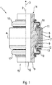
- Figure 1 shows a partially sectioned view of a first joint 1 according to the invention.
- the joint 1 is designed as a sleeve joint, namely a ball sleeve joint.
- the joint 1 is designed to be rotationally symmetrical to a joint axis or longitudinal center axis 2.
- the joint axis or longitudinal center axis 2 runs in the axial direction of the joint 1 according to arrow 3.
- the joint 1 is shown in a top view to the left of the longitudinal center axis 2, whereas a longitudinal section through the joint 1 is shown to the right of the longitudinal center axis 2.
- a transverse central axis 4 is arranged at right angles to the longitudinal central axis 2, the longitudinal central axis 2 and the transverse central axis 4 intersecting at a center point of the joint 1.
- An inner sleeve 6 is introduced into an outer sleeve 5.
- a joint socket 7 is arranged inside the inner sleeve 6.
- An inner joint part 8 is movably mounted in the joint socket 7.
- the joint socket 7 is designed as a ball socket and the inner joint part 8 as a ball sleeve.
- the inner joint part 8 has a joint ball 9 which is mounted rotatably and / or pivotably in relation to the joint socket 7.
- a through hole 10 extends through the inner joint part 8 in the axial direction 8.
- the through hole 10 is cylindrical here, for example.
- a locking ring 11 is pressed into the outer sleeve 5. The locking ring 11 rests axially on the joint socket 7 and the inner sleeve 6.
- the inner sleeve 6 has a material thickening or material reinforcement 12 extending radially inward.
- “radial” is to be understood as an alignment at right angles to the axial direction according to arrow 3 or the longitudinal center axis 2.
- the inner sleeve 6 has a contact surface 13. The contact surface 13 rests axially on the inside of the outer sleeve 5.
- the outer sleeve 5 engages around the inner sleeve 6 in the area of the material reinforcement 12.
- the inner joint part 8 extends axially out of the outer sleeve 5 on both sides and also axially through the locking ring 11 and the inner sleeve 6.
- Sealing bellows 16 and 17 are fastened to axial ends 14 and 15 of inner joint part 8 arranged outside of outer sleeve 5.
- the sealing bellows 16 extends from the axial end 14 to the locking ring 11 and is attached to it.
- the sealing bellows 17 extends from the axial end 15 to the inner sleeve 6 and is attached to it.
- axial ends 18, 19 of the outer sleeve 5 are each bent radially inward, so that the end 18 rests axially on the locking ring 11 and the end 19 rests axially on the contact surface 13.
- the axial ends 18, 19 can also fix the locking ring 11 and the inner sleeve 6 in a form-fitting manner in the outer sleeve 5.
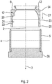
- Figure 2 shows a sectional view of the outer sleeve 5 and the inner sleeve 6 before they are assembled together.
- the inner sleeve 6 has a concave and / or spherical segment-shaped inner side area 20.
- the inner side area 20 of the outer sleeve 5 merges into an annular and / or cylindrical inner side area 21.
- a coaxially encircling recess 23 is made, which is delimited axially on both sides.
- the recess 23 is formed like a groove.
- the axially spaced apart edges of the inner sleeve 6 are designed as edge cylinders 24, 25 in this exemplary embodiment.
- the edge cylinders 24, 25 protrude radially outward beyond the recess 23.
- the inner sleeve 6 thus has a larger outer diameter in the area of the two edge cylinders 24, 25 than in the area of the recess 23.
- the outer diameter of the inner sleeve 6 in the area of the edge cylinders 24, 25 is greater than the inner diameter of the outer sleeve 5.
- Figure 2 and the one described in more detail below Figures 3 to 5 different steps for producing the joint 1 are shown.
- the outer sleeve 5 is placed on an assembly tool 26.
- the inner sleeve 6 is then pressed into the outer sleeve 5 in the direction of the arrow 3.
- the force required for pressing in is indicated by arrow 27.
- the outer diameter of the inner sleeve 6 is greater than the inner diameter of the outer sleeve 5, at least in the area of the edge cylinders 24, 25.
- Figure 3 shows a sectional view of the outer sleeve 5 with an installed inner sleeve 6.
- the inner sleeve 6 is arranged in the outer sleeve 5 with a press fit.
- the diameter of the inner sleeve 6 has been reduced and the diameter of the outer sleeve 5 has increased.
- These changes in diameter are indicated by arrows 28 and 29, respectively.
- the axial end 19 of the outer sleeve 5 has been reshaped radially inward, so that the axial end 19 rests against the contact surface 13 of the inner sleeve 6.
- the radial end 19 of the outer sleeve 5 extends at right angles to the longitudinal center axis 12.
- the contact surface 13 extends in the radial direction, namely at right angles to the longitudinal center axis 2 in this embodiment.
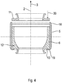
- Figure 4 shows a sectional view of the outer sleeve 5 with the mounted inner sleeve 6 according to FIG Figure 3 and before assembly of the locking ring 11.
- the outer sleeve 5 with the pressed-in inner sleeve 6 has been detached from the assembly tool 26 in order to then press the locking ring 11 into the outer sleeve 5 in the opposite direction of arrow 3 until the locking ring 11 rests axially on the inner sleeve 6 .
- the state before the locking ring 11 is pressed in can be seen, the force required for pressing in being indicated by arrow 30.
- the locking ring 11 is pressed into the outer sleeve 5 in a region of the axial end 18 facing away from the material reinforcement 12 or the axial end 19.
- the joint socket 7 and the inner joint part 8 are not shown in more detail for better clarity.
- the joint socket 7 and the inner joint part 8 are usually arranged in the inner sleeve 6. Only then is the locking ring 11 pressed into the outer sleeve 5.
- the joint socket 7 is pretensioned axially in the direction of the material reinforcement 12 of the inner sleeve 6 with the aid of the locking ring 11.
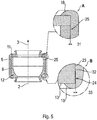
- FIG Figure 5 shows a sectional view of the outer sleeve 5 with the mounted inner sleeve 6 according to FIG Figure 3 and the assembled locking ring 11. Furthermore, FIG Figure 5 Two partial sections A and B. This shows the pressed-in state of the locking ring 11, whereby the outer diameter of the locking ring 11 was reduced due to the pressing-in of the locking ring 11 and the diameter of the outer sleeve 5 was increased at least in the area of the locking ring 11 and the edge cylinder 25.
- the enlargement of the diameter of the outer sleeve 5 brought about by the pressing in of the locking ring 11 can also be referred to as a radial expansion. This radial expansion is so large that the press fit of the inner sleeve 6 in the area of the edge cylinder 25 is released.
- a free space or gap 31 is thus created between the outer peripheral surface of the inner sleeve 6 in the area of the edge cylinder 25 and the inside of the outer sleeve 5 due to the pressing in of the locking ring 11.
- the axial end 18 of the outer sleeve 5 is reshaped radially inward.
- the locking ring 11 can be fixed in the axial direction according to arrow 3 between the axial end 18 and the inner sleeve 6.
- Partial section B shows a press-fit device 32.
- the press-fit device 32 is designed as an integral or one-piece component of the inner sleeve 6.
- the press-fit device 32 is designed as an annular web encircling the outer circumference of the inner sleeve 6.
- the press fit device 32 extends radially outward.
- the outer diameter of the press-fit device 32 is larger than the outer diameter of the inner sleeve 6 in the region of the edge cylinder 24, as a result of which the press-fit device projects radially outward beyond the edge cylinders 24, 25.
- the press-fit device 32 is arranged in the region of an edge of the edge cylinder 25.
- the press-fit device 32 is arranged in the area of an axially inwardly directed edge of the edge cylinder 24.
- the press-fit device 32 By means of the press-fit device 32, the inner sleeve 6 is pressed into the outer sleeve 5 in a fixed position, in particular in the radial direction, in the area of the edge cylinder 24. Compared to the edge cylinder 24, the press fit device 32 is designed to be comparatively narrow. Due to the press fit device 32, a free space or gap 33 is formed between the outer circumferential surface of the inner sleeve 6 in the area of the edge cylinder 24 and the inside of the outer sleeve 5.
- the press-fit device 32 has a barb contour. As a result, the risk of undesired loosening of the inner sleeve 6 in the axial direction can be further reduced.
- the gaps 31, 33 and the recess 23 form annular free spaces between the inner sleeve 6 and the outer sleeve 5.
- the locking ring 11 and the press-fit device 32 are matched to one another in such a way that the width of the gaps 31, 33 is identical or at least substantially the same are great.
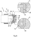
- FIG Figure 6 shows a partially sectioned view of the joint 1 according to the invention according to FIG Figure 1 after it has been pressed into a bearing eye 34.
- the joint shell 7 and the inner joint part 8 have been omitted.
- two partial sections C and D are shown.
- the bearing eye 34 is part of a chassis component 35.
- the chassis component 35 is designed as a link. To the left of the longitudinal center axis 2, part of the chassis component 35 is shown in plan view, with a part of the chassis component 35 being shown in section to the right of the longitudinal center axis 2.
- the bearing eye 34 is designed as a cylindrical through hole arranged in the chassis component 35. Due to the pressing of the joint 1 with the outer sleeve 5 into the bearing eye 34, the outer sleeve 5, the locking ring 11 and the inner sleeve 6 have been reduced in their diameters. Furthermore, the diameter of the bearing eye 34 was increased due to the press-fitting. The respective enlargements or reductions in diameter are indicated by means of arrows 36, 37 and 38.
- the gap 31 and the gap 33 have disappeared or the associated free space has been used up due to the diameter reduction of the outer sleeve 5.
- the recess 23 is still present between the two edge cylinders 24, 25.
- a reduction in the diameter of the inner sleeve 6 results in an increase in the radial prestressing of the joint socket 7, with the radial forces exerted by the joint socket 7 on the joint ball 9 being greatest, especially at the level of the edge cylinders 24, 25, when viewed in the axial direction 3.
- the joint 1 can absorb higher loads or forces in a preferred axial direction.
- the preferred axial direction for absorbing axial loads or forces is opposed to the axial direction according to arrow 3.
- the press-fit device 32 When the joint 1 is pressed into the bearing eye 34, due to the diameter reduction of the outer sleeve 5, the press-fit device 32 is deformed, reshaped and / or used up in such a way that the outer sleeve 5 lies in the area of the press-fit device 32 or the edge cylinder 24 on the outer circumferential surface of the inner sleeve 6 comes.
- the material of the press-fit device 32 can be pressed and / or reshaped into the outer sleeve 5 and / or in the direction of the recess 23.
- the material reinforcement 12 serves as a type of counter-bearing for the reshaping or deformation of the press-fit device 32 when the joint 1 or the outer sleeve 5 is pressed into the bearing eye 34.
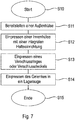
- FIG. 7 shows a schematic flow diagram for a method according to the invention.
- the outer sleeve 5 is provided according to step S11.
- the outer sleeve 5 is introduced into an assembly tool 26.
- the inner sleeve 6 is pressed into the outer sleeve 5.
- the inner sleeve 6 has a press-fit device 32 which is formed integrally or in one piece with the inner sleeve 6.
- the inner sleeve 6 in the area of the edge cylinders 24, 25 and the press-fit device 32 has an outer diameter that is larger than the inner diameter of the outer sleeve 5 Outer diameter of the two edge cylinders 24, 25.
- a press fit of the inner sleeve 6 is produced in the outer sleeve 5.
- the press fit device 32 and the edge cylinder 25, which is spaced apart from the press fit device 32 lie against the inside of the outer sleeve 5.
- the locking ring 11 is then pressed into the outer sleeve 5 in accordance with step S13.
- the locking ring 11 is pressed in immediately adjacent or adjacent to the edge cylinder 25. Before the locking ring 11 is pressed in, it has an outer diameter that is greater than the inner diameter of the outer sleeve 5.
- a gap 31 is formed by means of the locking ring 11 in the area of the edge cylinder 25 and a gap 33 is formed by means of the press-fit device 32 in the area of the edge cylinder 24.
- a closure cover can be used alternatively and instead of a locking ring 11 if the joint is designed as a ball and socket joint instead of a ball socket joint.
- step S14 the joint 1 is pressed into a bearing eye 34. Due to this press-in process, the diameter of the outer sleeve 5 is reduced and the free space due to the gaps 31, 33 is used up. Thus, the outer circumferential surfaces of the edge cylinders 24, 25 lie after the pressing of the joint 1 into the bearing eye 34 on the inside of the outer sleeve 5.
- the method according to the invention is then ended in accordance with step S15.
- the method according to the invention for producing the joint 1 can already be ended after step S13 has ended.
- the axial edge 19 of the outer sleeve 5 is reshaped radially inward after performing step S12 and before performing step S13.
- the axial end 18 of the outer sleeve 5 can be reshaped radially inward after the locking ring 11 has been pressed in according to step S13 and before step S14 or the end of the method. Due to the deformation of the axial ends 18, 19, the inner sleeve 6 and / or the joint socket 7 is fixed and / or pretensioned in the axial direction.
- Figure 8 4 shows a partially sectioned view of a further joint 39 according to the invention.
- the joint 39 is designed as a pivot joint, namely a ball pivot joint.
- the joint 39 is designed to be rotationally symmetrical to a joint axis or longitudinal center axis 2.
- the joint axis or longitudinal center axis 2 runs in the axial direction of the joint 39 according to arrow 3.
- the joint 39 is shown in a top view to the left of the longitudinal center axis 2, whereas a longitudinal section through the joint 39 is shown to the right of the longitudinal center axis 2.
- a transverse central axis 4 is arranged at right angles to the longitudinal central axis 2, the longitudinal central axis 2 and the transverse central axis 4 intersecting at a center point of the joint 1.
- An inner sleeve 6 is introduced into an outer sleeve 5.
- a joint socket 7 is arranged inside the inner sleeve 6.
- An inner joint part 40 is movably mounted in the joint socket 7.
- the joint socket 7 is embodied as a spherical socket and the inner joint part 40 is embodied as a ball pin.
- the inner joint part 40 has a joint ball 42 which is mounted rotatably and / or pivotably in relation to the joint socket 7.
- a closure cover 41 is pressed into the outer sleeve 5.
- the closure cover 41 rests axially on the joint socket 7 and the inner sleeve 6.
- the closure cap 41 is formed so as to be arched radially outward.
- the inner joint part 40 has a pin section 43.
- the pin section 43 is connected to the joint ball 42.
- the pin section 43 is essentially cylindrical.
- the pin portion 43 can be designed, for example, conical.
- the pin section 43 has a circumferential groove 44.
- the inner sleeve 6 In a region facing away from the closure cover 41 or at an end of the inner sleeve 6 facing away from the closure cover 41, the inner sleeve 6 has a material thickening or material reinforcement 12 extending radially inward. In the area of the material reinforcement 12 and on a side facing away from the closure cover 41, the inner sleeve 6 has a contact surface 13. The contact surface 13 rests axially on the inside of the outer sleeve 5. In this exemplary embodiment, the outer sleeve 5 engages around the inner sleeve 6 in the area of the material reinforcement 12.
- the inner joint part 40 extends axially out of the outer sleeve 5 by means of the pin section 43 and through the inner sleeve 6 on the side facing away from the closure cover 41.
- a sealing bellows 46 is attached to an axial end 45 of the outer sleeve 5 facing away from the closure cover 41.
- the sealing bellows 46 extends from an outer circumference of the pin section 43 to the inner sleeve 6 and is attached to it.
- axial ends 18, 19 of the outer sleeve 5 are each bent radially inward, so that the end 18 rests axially on the closure cover 41 and the end 19 rests axially on the contact surface 13.
- the axial ends 18, 19 can thus also fix the closure cover 41 and the inner sleeve 6 in a form-fitting manner in the outer sleeve 5.
- the manufacture or assembly of the joint 39 takes place analogously to the description of the joint 1 according to FIGS Figures 2 to 7 .
- the joint 39 thus also has a press fit device 32.
- a locking cover 41 is used instead of the locking ring 11 at the joint 39.
Landscapes
- Engineering & Computer Science (AREA)
- General Engineering & Computer Science (AREA)
- Mechanical Engineering (AREA)
- Pivots And Pivotal Connections (AREA)
- Vehicle Body Suspensions (AREA)
Claims (14)
- Articulation pour un véhicule comportant une douille extérieure (5), une cuvette d'articulation (7) destinée à recevoir une partie intérieure d'articulation (8, 40) montée mobile, une douille intérieure (6), qui est disposée au moins partiellement entre la cuvette d'articulation (7) et la douille extérieure (5), la douille intérieure (6) comprenant deux cylindres de bord (24, 25) espacés axialement l'un de l'autre, s'étendant au niveau de la périphérie extérieure de la douille intérieure (6) et faisant saillie radialement vers l'extérieur et les deux cylindres de bord (24, 25) définissant un évidement périphérique (23) sous la forme d'une rainure au niveau de la périphérie extérieure de la douille intérieure (6), caractérisée en ce qu'un dispositif d'ajustement serré (32) formé d'un seul tenant avec la douille intérieure (6) s'étend radialement vers l'extérieur au-delà du diamètre extérieur du cylindre de bord (24) dans la région d'au moins un cylindre de bord (24) de la douille intérieure (6).
- Articulation selon la revendication 1, caractérisée en ce que le dispositif d'ajustement serré (32) s'étend radialement vers l'extérieur à partir du cylindre de bord (24) de la douille intérieure (6), en particulier de la périphérie extérieure du cylindre de bord (24), et s'applique contre la douille extérieure (5).
- Articulation selon la revendication 1 ou 2, caractérisée en ce qu'une bague de fermeture (11) ou un couvercle de fermeture (41) est disposé(e) à l'intérieur de la douille extérieure (5), le dispositif d'ajustement serré (32) étant associé au cylindre de bord (24) opposé à la bague de fermeture (11) ou au couvercle de fermeture (41) .
- Articulation selon l'une des revendications précédentes, caractérisée en ce que le dispositif d'ajustement serré (32) est formé comme une arête, faisant saillie radialement vers l'extérieur, en particulier du cylindre de bord (24).
- Articulation selon l'une des revendications précédentes, caractérisée en ce que le dispositif d'ajustement serré (32) forme, en particulier dans un état assemblé de l'articulation (1, 39) et dans un état non monté par rapport à un composant de châssis (35), une fente (33) entre la douille extérieure (5) et le cylindre de bord (24) associé au dispositif d'ajustement serré (32) .
- Articulation selon l'une des revendications précédentes, caractérisée en ce que le dispositif d'ajustement serré (32) est formé pour réaliser une fonction de crochet et/ou pour retenir la douille intérieure (6) dans la douille extérieure (5) avant le montage de l'articulation (1, 39) dans un composant de châssis (35).
- Articulation selon l'une des revendications précédentes, caractérisée en ce que la douille intérieure (6) présente un épaississement de matériau et/ou un renforcement de matériau (12) orienté radialement vers l'intérieur dans la région du dispositif d'ajustement serré (32) et/ou du cylindre de bord (24) avec le dispositif d'ajustement serré (32) par comparaison avec le cylindre de bord (25) opposé au dispositif d'ajustement serré (32).
- Articulation selon l'une des revendications précédentes, caractérisée en ce qu'une bague de fermeture (11) ou un couvercle de fermeture (41) et la douille intérieure (6) avec le dispositif d'ajustement serré (32) d'un seul tenant sont pressés dans la douille extérieure (5) .
- Articulation selon l'une des revendications précédentes, caractérisée par une formation pour un composant de châssis (35) pour le montage sur un châssis d'un véhicule automobile, en particulier comme une articulation à tourillon sphérique ou comme une articulation à douille sphérique dotée d'un tourillon sphérique ou d'une douille sphérique comme partie intérieure d'articulation (8, 40) et d'une cuvette sphérique comme cuvette d'articulation (9).
- Procédé permettant de fabriquer une articulation (1, 39) selon l'une des revendications précédentes, dans lequel une douille intérieure (6) est introduite dans une douille extérieure (5), dans lequel une cuvette d'articulation (7) est disposée dans la douille intérieure (6), dans lequel une partie intérieure d'articulation (8, 40) est montée mobile dans la cuvette d'articulation (7), caractérisé en ce qu'un dispositif d'ajustement serré (32) disposé à l'intérieur de la douille extérieure (5) est pressé en tant qu'élément constitutif d'un seul tenant de la douille intérieure (6) dans la douille extérieure (5) pour élargir la douille extérieure (5) au moins partiellement radialement.
- Procédé selon la revendication 10, caractérisé en ce que le dispositif d'ajustement serré (32) s'étendant radialement dans la direction de la douille extérieure (5) est disposé dans la région d'un cylindre de bord (24) de la douille intérieure (6), seulement le dispositif d'ajustement serré (32) étant amené en contact avec un côté intérieur de la douille extérieure (5) dans la région du cylindre de bord (24) lors du pressage de la douille intérieure (6) dans la douille extérieure (5).
- Procédé selon la revendication 10 ou 11, caractérisé en ce que tout d'abord la douille intérieure (6) avec le dispositif d'ajustement serré (32) et ensuite une bague de fermeture (11) ou un couvercle de fermeture (41) sont pressés dans la douille extérieure (5), la douille extérieure (5) étant élargie radialement au moins partiellement au moyen de la bague de fermeture (11) ou du couvercle de fermeture (41).
- Procédé selon l'une des revendications 10 à 12, caractérisé en ce qu'en raison du pressage de la douille intérieure (6) et d'une bague de fermeture (11) ou d'un couvercle de fermeture (41), une fente (31, 33) est formée respectivement entre des cylindres de bord (24, 25) espacés dans la direction axiale de la douille intérieure (6) et la douille extérieure (5).
- Procédé selon la revendication 13, caractérisé en ce qu'après le pressage de la douille intérieure, et en particulier de la bague de fermeture (11) ou du couvercle de fermeture (41), la douille extérieure (5) est pressée dans un œil de palier (34) d'un composant de châssis (35), de sorte que les cylindres de bord (24, 25) de la douille intérieure (6) soient appliqués et/ou pressés contre le côté intérieur de la douille extérieure (5).
Applications Claiming Priority (2)
| Application Number | Priority Date | Filing Date | Title |
|---|---|---|---|
| DE102016225127.9A DE102016225127A1 (de) | 2016-12-15 | 2016-12-15 | Gelenk für ein Fahrzeug und Verfahren zum Herstellen eines solchen Gelenkes |
| PCT/EP2017/079259 WO2018108418A1 (fr) | 2016-12-15 | 2017-11-15 | Articulation pour un véhicule et procédé permettant de fabriquer une telle articulation |
Publications (2)
| Publication Number | Publication Date |
|---|---|
| EP3554867A1 EP3554867A1 (fr) | 2019-10-23 |
| EP3554867B1 true EP3554867B1 (fr) | 2021-06-09 |
Family
ID=60331607
Family Applications (1)
| Application Number | Title | Priority Date | Filing Date |
|---|---|---|---|
| EP17798193.3A Active EP3554867B1 (fr) | 2016-12-15 | 2017-11-15 | Articulation pour un véhicule et procédé permettant de fabriquer une telle articulation |
Country Status (7)
| Country | Link |
|---|---|
| US (1) | US11041522B2 (fr) |
| EP (1) | EP3554867B1 (fr) |
| JP (1) | JP2020502436A (fr) |
| KR (1) | KR20190097008A (fr) |
| CN (1) | CN110087916A (fr) |
| DE (1) | DE102016225127A1 (fr) |
| WO (1) | WO2018108418A1 (fr) |
Families Citing this family (1)
| Publication number | Priority date | Publication date | Assignee | Title |
|---|---|---|---|---|
| DE102015213687A1 (de) * | 2015-07-21 | 2017-01-26 | Zf Friedrichshafen Ag | Kugelzapfen mit einem aufgepressten Ringkörper und Kugelgelenk mit einem solchen Kugelzapfen |
Family Cites Families (10)
| Publication number | Priority date | Publication date | Assignee | Title |
|---|---|---|---|---|
| JPS6263414U (fr) * | 1985-10-11 | 1987-04-20 | ||
| DE4109697C1 (fr) * | 1991-03-23 | 1992-06-25 | Trw Ehrenreich Gmbh & Co Kg, 4000 Duesseldorf, De | |
| GB2418963B (en) | 2004-10-06 | 2007-04-04 | Minebea Co Ltd | A bearing assembly |
| DE102004056575B4 (de) * | 2004-11-23 | 2010-09-23 | Zf Friedrichshafen Ag | Gelenk- und/oder Lageranordnung |
| DE102006061974A1 (de) | 2006-12-21 | 2008-07-10 | Zf Friedrichshafen Ag | Kugelgelenk mit Verschlussring |
| US20110026862A1 (en) * | 2008-04-07 | 2011-02-03 | Sven Bjoerkgard | Reaction rod arrangement |
| DE102009016139A1 (de) * | 2009-04-03 | 2010-10-14 | Trw Automotive Gmbh | Elastomergelenk |
| DE102010041306A1 (de) * | 2010-09-24 | 2012-03-29 | Zf Friedrichshafen Ag | Verfahren zum Herstellen eines Kugelhülsengelenks |
| DE102012207527B4 (de) * | 2012-05-07 | 2022-12-29 | Zf Friedrichshafen Ag | Hülsengelenk für ein Fahrzeug |
| DE102014003324B4 (de) * | 2014-03-08 | 2015-11-26 | Audi Ag | Gummi-Metall-Hülsenlager |
-
2016
- 2016-12-15 DE DE102016225127.9A patent/DE102016225127A1/de not_active Withdrawn
-
2017
- 2017-11-15 JP JP2019528028A patent/JP2020502436A/ja active Pending
- 2017-11-15 WO PCT/EP2017/079259 patent/WO2018108418A1/fr not_active Ceased
- 2017-11-15 CN CN201780077167.XA patent/CN110087916A/zh active Pending
- 2017-11-15 KR KR1020197016812A patent/KR20190097008A/ko not_active Withdrawn
- 2017-11-15 EP EP17798193.3A patent/EP3554867B1/fr active Active
- 2017-11-15 US US16/348,646 patent/US11041522B2/en not_active Expired - Fee Related
Non-Patent Citations (1)
| Title |
|---|
| None * |
Also Published As
| Publication number | Publication date |
|---|---|
| CN110087916A (zh) | 2019-08-02 |
| JP2020502436A (ja) | 2020-01-23 |
| US20190293111A1 (en) | 2019-09-26 |
| US11041522B2 (en) | 2021-06-22 |
| EP3554867A1 (fr) | 2019-10-23 |
| KR20190097008A (ko) | 2019-08-20 |
| WO2018108418A1 (fr) | 2018-06-21 |
| DE102016225127A1 (de) | 2018-06-21 |
Similar Documents
| Publication | Publication Date | Title |
|---|---|---|
| DE69215290T2 (de) | Verstellbare Buchse | |
| DE102012207527B4 (de) | Hülsengelenk für ein Fahrzeug | |
| DE112014004355T9 (de) | Rohrförmige Schwingungsdämpfungsvorrichtung | |
| EP2414180B1 (fr) | Articulation elastomere | |
| EP1525406B1 (fr) | Moyeu montable par pression et arbre a cames | |
| EP1463891A1 (fr) | Joint a rotule | |
| DE60020754T2 (de) | Verfahren zu ihrer Herstellung einer wälzgelagerten Radlagereinheit | |
| DE102014013077B4 (de) | Elastomerlager als Buchsenlager | |
| DE102011052398B4 (de) | Lageranordnung | |
| EP1736681A1 (fr) | Manchon avec butée radiale et/ou axiale et procédé pour la réalisation d'une butée axiale d'un manchon | |
| WO2018202386A1 (fr) | Clapet d'amortissement pour amortisseur de vibrations | |
| WO2006128436A1 (fr) | Ensemble articulation et/ou palier | |
| DE102016123364B4 (de) | Klemmvorrichtung und Verfahren zur Herstellung von Klemmvorrichtungen | |
| EP1691104B1 (fr) | Support élastique | |
| EP3554867B1 (fr) | Articulation pour un véhicule et procédé permettant de fabriquer une telle articulation | |
| EP1815155A1 (fr) | Ensemble d'articulation et/ou de logement | |
| DE102007037704A1 (de) | Lageranordnung mit einer Lagerbuchse und Verfahren zur Herstellung einer Lagerbuchse einer Lageranordnung | |
| DE69700991T2 (de) | Federringe | |
| DE202006000285U1 (de) | Elastomer-Metall-Gelenklager, insbesondere als Zentralgelenklager eines Dreieckslenkers zur Verbindung eines Achskörpers mit einem Fahrzeugaufbau | |
| EP3608552B1 (fr) | Joint pivotant | |
| EP1820994B1 (fr) | Pendule, en particulier pour le train d'atterrissage d'un véhicule utilitaire | |
| DE19723739C2 (de) | Radführung für ein Kraftfahrzeug | |
| DE102018217994A1 (de) | Schlepprollenhohlachse, Schlepprollenmontageset, Fahrtreppenstufe umfassend eine Schlepprollenhohlachse sowie Verfahren zur Montage einer Schlepprolle unter Verwendung eines Schlepprollenmontagesets | |
| DE102007045807A1 (de) | Stabilisierungsbuchse | |
| DE102021201721A1 (de) | Mehrpunktlenker für ein Fahrwerk |
Legal Events
| Date | Code | Title | Description |
|---|---|---|---|
| STAA | Information on the status of an ep patent application or granted ep patent |
Free format text: STATUS: UNKNOWN |
|
| STAA | Information on the status of an ep patent application or granted ep patent |
Free format text: STATUS: THE INTERNATIONAL PUBLICATION HAS BEEN MADE |
|
| PUAI | Public reference made under article 153(3) epc to a published international application that has entered the european phase |
Free format text: ORIGINAL CODE: 0009012 |
|
| STAA | Information on the status of an ep patent application or granted ep patent |
Free format text: STATUS: REQUEST FOR EXAMINATION WAS MADE |
|
| 17P | Request for examination filed |
Effective date: 20190514 |
|
| AK | Designated contracting states |
Kind code of ref document: A1 Designated state(s): AL AT BE BG CH CY CZ DE DK EE ES FI FR GB GR HR HU IE IS IT LI LT LU LV MC MK MT NL NO PL PT RO RS SE SI SK SM TR |
|
| AX | Request for extension of the european patent |
Extension state: BA ME |
|
| DAV | Request for validation of the european patent (deleted) | ||
| DAX | Request for extension of the european patent (deleted) | ||
| REG | Reference to a national code |
Ref country code: DE Ref legal event code: R079 Ref document number: 502017010632 Country of ref document: DE Free format text: PREVIOUS MAIN CLASS: B60G0007000000 Ipc: F16C0011060000 |
|
| RIC1 | Information provided on ipc code assigned before grant |
Ipc: F16C 11/06 20060101AFI20201127BHEP Ipc: B60G 7/00 20060101ALI20201127BHEP |
|
| GRAP | Despatch of communication of intention to grant a patent |
Free format text: ORIGINAL CODE: EPIDOSNIGR1 |
|
| STAA | Information on the status of an ep patent application or granted ep patent |
Free format text: STATUS: GRANT OF PATENT IS INTENDED |
|
| INTG | Intention to grant announced |
Effective date: 20210122 |
|
| GRAS | Grant fee paid |
Free format text: ORIGINAL CODE: EPIDOSNIGR3 |
|
| GRAA | (expected) grant |
Free format text: ORIGINAL CODE: 0009210 |
|
| STAA | Information on the status of an ep patent application or granted ep patent |
Free format text: STATUS: THE PATENT HAS BEEN GRANTED |
|
| AK | Designated contracting states |
Kind code of ref document: B1 Designated state(s): AL AT BE BG CH CY CZ DE DK EE ES FI FR GB GR HR HU IE IS IT LI LT LU LV MC MK MT NL NO PL PT RO RS SE SI SK SM TR |
|
| REG | Reference to a national code |
Ref country code: GB Ref legal event code: FG4D Free format text: NOT ENGLISH |
|
| REG | Reference to a national code |
Ref country code: CH Ref legal event code: EP Ref country code: AT Ref legal event code: REF Ref document number: 1400748 Country of ref document: AT Kind code of ref document: T Effective date: 20210615 |
|
| REG | Reference to a national code |
Ref country code: DE Ref legal event code: R096 Ref document number: 502017010632 Country of ref document: DE |
|
| REG | Reference to a national code |
Ref country code: IE Ref legal event code: FG4D Free format text: LANGUAGE OF EP DOCUMENT: GERMAN |
|
| REG | Reference to a national code |
Ref country code: LT Ref legal event code: MG9D |
|
| PG25 | Lapsed in a contracting state [announced via postgrant information from national office to epo] |
Ref country code: FI Free format text: LAPSE BECAUSE OF FAILURE TO SUBMIT A TRANSLATION OF THE DESCRIPTION OR TO PAY THE FEE WITHIN THE PRESCRIBED TIME-LIMIT Effective date: 20210609 Ref country code: LT Free format text: LAPSE BECAUSE OF FAILURE TO SUBMIT A TRANSLATION OF THE DESCRIPTION OR TO PAY THE FEE WITHIN THE PRESCRIBED TIME-LIMIT Effective date: 20210609 Ref country code: BG Free format text: LAPSE BECAUSE OF FAILURE TO SUBMIT A TRANSLATION OF THE DESCRIPTION OR TO PAY THE FEE WITHIN THE PRESCRIBED TIME-LIMIT Effective date: 20210909 Ref country code: HR Free format text: LAPSE BECAUSE OF FAILURE TO SUBMIT A TRANSLATION OF THE DESCRIPTION OR TO PAY THE FEE WITHIN THE PRESCRIBED TIME-LIMIT Effective date: 20210609 |
|
| REG | Reference to a national code |
Ref country code: NL Ref legal event code: MP Effective date: 20210609 |
|
| PG25 | Lapsed in a contracting state [announced via postgrant information from national office to epo] |
Ref country code: GR Free format text: LAPSE BECAUSE OF FAILURE TO SUBMIT A TRANSLATION OF THE DESCRIPTION OR TO PAY THE FEE WITHIN THE PRESCRIBED TIME-LIMIT Effective date: 20210910 Ref country code: NO Free format text: LAPSE BECAUSE OF FAILURE TO SUBMIT A TRANSLATION OF THE DESCRIPTION OR TO PAY THE FEE WITHIN THE PRESCRIBED TIME-LIMIT Effective date: 20210909 Ref country code: LV Free format text: LAPSE BECAUSE OF FAILURE TO SUBMIT A TRANSLATION OF THE DESCRIPTION OR TO PAY THE FEE WITHIN THE PRESCRIBED TIME-LIMIT Effective date: 20210609 Ref country code: SE Free format text: LAPSE BECAUSE OF FAILURE TO SUBMIT A TRANSLATION OF THE DESCRIPTION OR TO PAY THE FEE WITHIN THE PRESCRIBED TIME-LIMIT Effective date: 20210609 Ref country code: RS Free format text: LAPSE BECAUSE OF FAILURE TO SUBMIT A TRANSLATION OF THE DESCRIPTION OR TO PAY THE FEE WITHIN THE PRESCRIBED TIME-LIMIT Effective date: 20210609 |
|
| PG25 | Lapsed in a contracting state [announced via postgrant information from national office to epo] |
Ref country code: SM Free format text: LAPSE BECAUSE OF FAILURE TO SUBMIT A TRANSLATION OF THE DESCRIPTION OR TO PAY THE FEE WITHIN THE PRESCRIBED TIME-LIMIT Effective date: 20210609 Ref country code: SK Free format text: LAPSE BECAUSE OF FAILURE TO SUBMIT A TRANSLATION OF THE DESCRIPTION OR TO PAY THE FEE WITHIN THE PRESCRIBED TIME-LIMIT Effective date: 20210609 Ref country code: ES Free format text: LAPSE BECAUSE OF FAILURE TO SUBMIT A TRANSLATION OF THE DESCRIPTION OR TO PAY THE FEE WITHIN THE PRESCRIBED TIME-LIMIT Effective date: 20210609 Ref country code: NL Free format text: LAPSE BECAUSE OF FAILURE TO SUBMIT A TRANSLATION OF THE DESCRIPTION OR TO PAY THE FEE WITHIN THE PRESCRIBED TIME-LIMIT Effective date: 20210609 Ref country code: RO Free format text: LAPSE BECAUSE OF FAILURE TO SUBMIT A TRANSLATION OF THE DESCRIPTION OR TO PAY THE FEE WITHIN THE PRESCRIBED TIME-LIMIT Effective date: 20210609 Ref country code: PT Free format text: LAPSE BECAUSE OF FAILURE TO SUBMIT A TRANSLATION OF THE DESCRIPTION OR TO PAY THE FEE WITHIN THE PRESCRIBED TIME-LIMIT Effective date: 20211011 Ref country code: EE Free format text: LAPSE BECAUSE OF FAILURE TO SUBMIT A TRANSLATION OF THE DESCRIPTION OR TO PAY THE FEE WITHIN THE PRESCRIBED TIME-LIMIT Effective date: 20210609 Ref country code: CZ Free format text: LAPSE BECAUSE OF FAILURE TO SUBMIT A TRANSLATION OF THE DESCRIPTION OR TO PAY THE FEE WITHIN THE PRESCRIBED TIME-LIMIT Effective date: 20210609 |
|
| PG25 | Lapsed in a contracting state [announced via postgrant information from national office to epo] |
Ref country code: PL Free format text: LAPSE BECAUSE OF FAILURE TO SUBMIT A TRANSLATION OF THE DESCRIPTION OR TO PAY THE FEE WITHIN THE PRESCRIBED TIME-LIMIT Effective date: 20210609 |
|
| REG | Reference to a national code |
Ref country code: DE Ref legal event code: R097 Ref document number: 502017010632 Country of ref document: DE |
|
| PLBE | No opposition filed within time limit |
Free format text: ORIGINAL CODE: 0009261 |
|
| STAA | Information on the status of an ep patent application or granted ep patent |
Free format text: STATUS: NO OPPOSITION FILED WITHIN TIME LIMIT |
|
| PG25 | Lapsed in a contracting state [announced via postgrant information from national office to epo] |
Ref country code: DK Free format text: LAPSE BECAUSE OF FAILURE TO SUBMIT A TRANSLATION OF THE DESCRIPTION OR TO PAY THE FEE WITHIN THE PRESCRIBED TIME-LIMIT Effective date: 20210609 |
|
| 26N | No opposition filed |
Effective date: 20220310 |
|
| PG25 | Lapsed in a contracting state [announced via postgrant information from national office to epo] |
Ref country code: AL Free format text: LAPSE BECAUSE OF FAILURE TO SUBMIT A TRANSLATION OF THE DESCRIPTION OR TO PAY THE FEE WITHIN THE PRESCRIBED TIME-LIMIT Effective date: 20210609 |
|
| PG25 | Lapsed in a contracting state [announced via postgrant information from national office to epo] |
Ref country code: MC Free format text: LAPSE BECAUSE OF FAILURE TO SUBMIT A TRANSLATION OF THE DESCRIPTION OR TO PAY THE FEE WITHIN THE PRESCRIBED TIME-LIMIT Effective date: 20210609 |
|
| REG | Reference to a national code |
Ref country code: CH Ref legal event code: PL |
|
| GBPC | Gb: european patent ceased through non-payment of renewal fee |
Effective date: 20211115 |
|
| PG25 | Lapsed in a contracting state [announced via postgrant information from national office to epo] |
Ref country code: LU Free format text: LAPSE BECAUSE OF NON-PAYMENT OF DUE FEES Effective date: 20211115 Ref country code: IT Free format text: LAPSE BECAUSE OF FAILURE TO SUBMIT A TRANSLATION OF THE DESCRIPTION OR TO PAY THE FEE WITHIN THE PRESCRIBED TIME-LIMIT Effective date: 20210609 Ref country code: BE Free format text: LAPSE BECAUSE OF NON-PAYMENT OF DUE FEES Effective date: 20211130 |
|
| REG | Reference to a national code |
Ref country code: BE Ref legal event code: MM Effective date: 20211130 |
|
| PG25 | Lapsed in a contracting state [announced via postgrant information from national office to epo] |
Ref country code: LI Free format text: LAPSE BECAUSE OF NON-PAYMENT OF DUE FEES Effective date: 20211130 Ref country code: CH Free format text: LAPSE BECAUSE OF NON-PAYMENT OF DUE FEES Effective date: 20211130 |
|
| PG25 | Lapsed in a contracting state [announced via postgrant information from national office to epo] |
Ref country code: IE Free format text: LAPSE BECAUSE OF NON-PAYMENT OF DUE FEES Effective date: 20211115 Ref country code: GB Free format text: LAPSE BECAUSE OF NON-PAYMENT OF DUE FEES Effective date: 20211115 |
|
| PG25 | Lapsed in a contracting state [announced via postgrant information from national office to epo] |
Ref country code: FR Free format text: LAPSE BECAUSE OF NON-PAYMENT OF DUE FEES Effective date: 20211130 |
|
| PG25 | Lapsed in a contracting state [announced via postgrant information from national office to epo] |
Ref country code: CY Free format text: LAPSE BECAUSE OF FAILURE TO SUBMIT A TRANSLATION OF THE DESCRIPTION OR TO PAY THE FEE WITHIN THE PRESCRIBED TIME-LIMIT Effective date: 20210609 |
|
| P01 | Opt-out of the competence of the unified patent court (upc) registered |
Effective date: 20230528 |
|
| PG25 | Lapsed in a contracting state [announced via postgrant information from national office to epo] |
Ref country code: HU Free format text: LAPSE BECAUSE OF FAILURE TO SUBMIT A TRANSLATION OF THE DESCRIPTION OR TO PAY THE FEE WITHIN THE PRESCRIBED TIME-LIMIT; INVALID AB INITIO Effective date: 20171115 |
|
| REG | Reference to a national code |
Ref country code: AT Ref legal event code: MM01 Ref document number: 1400748 Country of ref document: AT Kind code of ref document: T Effective date: 20221115 |
|
| PG25 | Lapsed in a contracting state [announced via postgrant information from national office to epo] |
Ref country code: AT Free format text: LAPSE BECAUSE OF NON-PAYMENT OF DUE FEES Effective date: 20221115 |
|
| PG25 | Lapsed in a contracting state [announced via postgrant information from national office to epo] |
Ref country code: MK Free format text: LAPSE BECAUSE OF FAILURE TO SUBMIT A TRANSLATION OF THE DESCRIPTION OR TO PAY THE FEE WITHIN THE PRESCRIBED TIME-LIMIT Effective date: 20210609 |
|
| PG25 | Lapsed in a contracting state [announced via postgrant information from national office to epo] |
Ref country code: MT Free format text: LAPSE BECAUSE OF FAILURE TO SUBMIT A TRANSLATION OF THE DESCRIPTION OR TO PAY THE FEE WITHIN THE PRESCRIBED TIME-LIMIT Effective date: 20210609 |
|
| PG25 | Lapsed in a contracting state [announced via postgrant information from national office to epo] |
Ref country code: TR Free format text: LAPSE BECAUSE OF FAILURE TO SUBMIT A TRANSLATION OF THE DESCRIPTION OR TO PAY THE FEE WITHIN THE PRESCRIBED TIME-LIMIT Effective date: 20210609 |
|
| PGFP | Annual fee paid to national office [announced via postgrant information from national office to epo] |
Ref country code: DE Payment date: 20250923 Year of fee payment: 9 |