EP3555689B1 - Dispositif de conversion de lumière - Google Patents
Dispositif de conversion de lumière Download PDFInfo
- Publication number
- EP3555689B1 EP3555689B1 EP17818476.8A EP17818476A EP3555689B1 EP 3555689 B1 EP3555689 B1 EP 3555689B1 EP 17818476 A EP17818476 A EP 17818476A EP 3555689 B1 EP3555689 B1 EP 3555689B1
- Authority
- EP
- European Patent Office
- Prior art keywords
- light
- cooling element
- laser
- converter
- converting device
- Prior art date
- Legal status (The legal status is an assumption and is not a legal conclusion. Google has not performed a legal analysis and makes no representation as to the accuracy of the status listed.)
- Active
Links
Images


Classifications
-
- F—MECHANICAL ENGINEERING; LIGHTING; HEATING; WEAPONS; BLASTING
- F21—LIGHTING
- F21S—NON-PORTABLE LIGHTING DEVICES; SYSTEMS THEREOF; VEHICLE LIGHTING DEVICES SPECIALLY ADAPTED FOR VEHICLE EXTERIORS
- F21S41/00—Illuminating devices specially adapted for vehicle exteriors, e.g. headlamps
- F21S41/10—Illuminating devices specially adapted for vehicle exteriors, e.g. headlamps characterised by the light source
- F21S41/14—Illuminating devices specially adapted for vehicle exteriors, e.g. headlamps characterised by the light source characterised by the type of light source
- F21S41/176—Light sources where the light is generated by photoluminescent material spaced from a primary light generating element
-
- G—PHYSICS
- G02—OPTICS
- G02B—OPTICAL ELEMENTS, SYSTEMS OR APPARATUS
- G02B19/00—Condensers, e.g. light collectors or similar non-imaging optics
- G02B19/0033—Condensers, e.g. light collectors or similar non-imaging optics characterised by the use
- G02B19/0047—Condensers, e.g. light collectors or similar non-imaging optics characterised by the use for use with a light source
- G02B19/0052—Condensers, e.g. light collectors or similar non-imaging optics characterised by the use for use with a light source the light source comprising a laser diode
-
- F—MECHANICAL ENGINEERING; LIGHTING; HEATING; WEAPONS; BLASTING
- F21—LIGHTING
- F21S—NON-PORTABLE LIGHTING DEVICES; SYSTEMS THEREOF; VEHICLE LIGHTING DEVICES SPECIALLY ADAPTED FOR VEHICLE EXTERIORS
- F21S41/00—Illuminating devices specially adapted for vehicle exteriors, e.g. headlamps
- F21S41/10—Illuminating devices specially adapted for vehicle exteriors, e.g. headlamps characterised by the light source
- F21S41/14—Illuminating devices specially adapted for vehicle exteriors, e.g. headlamps characterised by the light source characterised by the type of light source
- F21S41/16—Laser light sources
-
- F—MECHANICAL ENGINEERING; LIGHTING; HEATING; WEAPONS; BLASTING
- F21—LIGHTING
- F21S—NON-PORTABLE LIGHTING DEVICES; SYSTEMS THEREOF; VEHICLE LIGHTING DEVICES SPECIALLY ADAPTED FOR VEHICLE EXTERIORS
- F21S41/00—Illuminating devices specially adapted for vehicle exteriors, e.g. headlamps
- F21S41/30—Illuminating devices specially adapted for vehicle exteriors, e.g. headlamps characterised by reflectors
-
- F—MECHANICAL ENGINEERING; LIGHTING; HEATING; WEAPONS; BLASTING
- F21—LIGHTING
- F21S—NON-PORTABLE LIGHTING DEVICES; SYSTEMS THEREOF; VEHICLE LIGHTING DEVICES SPECIALLY ADAPTED FOR VEHICLE EXTERIORS
- F21S45/00—Arrangements within vehicle lighting devices specially adapted for vehicle exteriors, for purposes other than emission or distribution of light
- F21S45/40—Cooling of lighting devices
- F21S45/47—Passive cooling, e.g. using fins, thermal conductive elements or openings
-
- F—MECHANICAL ENGINEERING; LIGHTING; HEATING; WEAPONS; BLASTING
- F21—LIGHTING
- F21V—FUNCTIONAL FEATURES OR DETAILS OF LIGHTING DEVICES OR SYSTEMS THEREOF; STRUCTURAL COMBINATIONS OF LIGHTING DEVICES WITH OTHER ARTICLES, NOT OTHERWISE PROVIDED FOR
- F21V7/00—Reflectors for light sources
- F21V7/22—Reflectors for light sources characterised by materials, surface treatments or coatings, e.g. dichroic reflectors
Definitions
- the invention relates to a light converting device, a light emitting element, a laser-based light source comprising such a light converting device or such a light emitting device, and a vehicle headlight comprising such a laser-based light source.
- a light converting device In high luminance light sources often a light converting device is used that is excited by e.g. blue light emitted by a laser.
- a phosphor of the light converting device is coupled to a heatsink by means of a layer of glue or solder which is provided between the heatsink and the phosphor.
- the high intensity especially of blue laser light and the high temperature caused by the light conversion by means of the phosphor may cause reliability issues.
- WO2015121089A1 EP2822111A1 , US20130335989A1 and WO2009095662A1 proposed specific cooling structures for the phosphor.
- US20130335989A1 describes a headlamp that includes a semiconductor laser; a light-emitting element that emits light in response to laser light emitted from the semiconductor laser; a heat-conducting member that receives heat generated by the light-emitting element through a light-emitting-element facing surface; and a gap layer that is disposed between the light-emitting element and the light-emitting-element facing surface and that conducts the heat generated by the light-emitting element to the light-emitting-element facing surface.
- the gap layer contains at least an inorganic amorphous material.
- WO2009095662A1 describes a light emitting module with improved optical functionality and reduced thermal resistance, which comprises a light emitting device (LED), a wavelength converting (WC) element and an inorganic optically-transmissive thermally-conductive (OTTC) element.
- the WC element is capable of absorbing light generated from the LED at a specific wavelength and re-emitting light having a different wavelength. The re-emitted light and any unabsorbed light exits through at least one surface of the module.
- the OTTC is in physical contact with the WC element and at least partially located in the optical path of the light.
- the OTTC comprises one or more layers of inorganic material having a thermal conductivity greater than that of the WC element.
- a light converting device is provided, as further defined in claim 1.
- The, for example, blue laser light and the converted light are preferably diffusely reflected by means of the reflective structure or a combination of the reflective structure and corresponding scattering elements within, for example, the light converter.
- a part of the reflected light may hit the reflective side structure.
- a part of the light hitting the reflective side structure may be absorbed and may cause unwanted local heating of the reflective side structure. This local heating may damage the reflective side structure such that especially back reflection of the blue laser light in the light converter may be reduced. This may influence the intensity and/or color point of the light which can be emitted by means of the light converting device.
- the cooling element is in thermal contact with the reflective side structure and has preferably a thermal conductance of more than 10 W/K, more preferably of more than 20 W/K and most preferably of more than 30 W/K.
- the size and shape of the cooling element has to be adapted to the amount of heat generated at the reflective side structure.
- Sapphire has a thermal conductance of around 40W/K (thermal conductivity of around 40 W/(mK)).
- the cooling element may therefore remove or dissipate a substantial part of the heat generated in or at the reflective side structure such that damage of the reflective side structure is reduced. Aging of materials comprised by the reflective side structure may, thus, be delayed.
- the light converter may, for example, be a thin (e.g. 50 ⁇ m) rectangular or circular plate. The thin sides of the light converter may be covered with the reflective side structure.
- the light converting device comprises a decoupling structure.
- the decoupling structure is arranged between the light converter and the cooling element.
- the decoupling structure is arranged to avoid light guiding of the reflected laser light and the converted light in the cooling element.
- a refractive index of the decoupling structure may be the same or less than a refractive index of the material at a surface of the cooling element opposite a surface of the cooling element facing the light converter.
- Light guiding may, for example, be avoided by reducing or even avoiding a direct interface between the cooling element and the light converter.
- the cooling element and the light converter may be arranged such that only a minor part of the facing surfaces touch each other.
- Surface roughness of the surface of the light converter and/or the surface of the cooling element may, for example, be arranged such that less than 5%, preferably less than 3% and most preferably less than 1% of the surfaces of the light converter and the cooling element superimposed upon each other touch each other. There may be an air gap between the cooling element and the light converter in an alternative approach.
- the decoupling structure is preferably arranged such that essentially all light entering the cooling element in the direction from the light converter leaves the transparent cooling element at the opposite side.
- the cooling element may, for example, comprise a sheet of sapphire.
- the cooling element is preferably bonded to the substrate by means of the reflective side structure.
- the reflective side structure comprises a matrix material which is transparent in the wavelength range of the laser light and the wavelength range of the converted light.
- the matrix material comprises reflective particles dispersed in the matrix material, wherein the reflective particles are reflective in the wavelength range of the laser light and the wavelength range of the converted light.
- the matrix material comprising the reflective particles is disposed on the side surface of the light converter.
- the cooling element may be bonded to the substrate by means of the matrix material.
- the matrix material may be characterized by a means of a transmission of more than 99% in the wavelength ranges of the laser light and the converted light along the biggest extension of the reflective light structure. High transparency of the matrix material reduces absorption within the matrix material and thus corresponding heating.
- the matrix material may comprise silicone, glass or other suitable materials which can be used as side coating in order to provide a reflective side structure.
- the reflective particles may comprise, for example, metal oxide particles especially titanium oxide particles.
- the transparent cooling element may comprise an antireflective coating for reducing its reflectivity for laser light and converted light.
- the antireflective coating is especially in case of a flat, sheet like transparent cooling element preferably provided on both sheet surfaces of the transparent cooling element, i.e., on the surface facing the light converter as well as on the opposite surface.
- the transparent cooling element may alternatively comprise a curved surface for e.g. focusing the converted light and the reflected laser light.
- the transparent cooling element may in this case comprise only one antireflective coating.
- the antireflective coating is arranged to avoid reflection of e.g. blue laser light which is used to irradiate the light converter and such that essentially all light emitted by the light converter (or to be more precise irradiating the transparent cooling element from the direction of the light converter) can enter and subsequently leave the transparent cooling element.
- the cooling element may comprise a support structure.
- the support structure may be arranged to define a distance between the light entrance surface of the light converter and the cooling element perpendicular to the light entrance surface.
- the support structure may be an integrated part of the cooling element or a part which can be separated.
- the support structure may comprise a different material than the rest of the cooling element.
- the support structure may be glued or bonded to the substrate and/or to the rest of the cooling element.
- a light emitting element comprises the light converting device as described above.
- the light emitting element further comprises an optical element.
- the optical element is mechanically coupled or adhered to the cooling element by means of a bonding layer.
- the bonding layer has a refractive index which is the same or greater than the refractive index of the decoupling structure.
- the decoupling structure comprises an air gap as described above or a decoupling material (e.g. silicone) arranged between the light converter and the cooling element which has the same or a lower refractive index than the glue or adhesive used for bonding the optical element.
- the laser based light source comprises a light converting device or a light emitting device as described above and at least one laser which is adapted to emit the laser light.
- the laser-based light source may comprise two, three, four or more lasers (e.g. the form of an array) emitting, for example, blue laser light.
- a vehicle headlight comprises at least one laser-based light source as described above.
- the vehicle headlight may comprise two, three, four or more laser-based light sources as described above.
- the light converter may in this case comprise or consist of a yellow phosphor garnet (e.g. Y (3-0.4) Gd 0.4 ,Al 5 O 12 :Ce).
- a mixture of blue laser light and yellow converted light may be used to generate white light.
- Around 21% of the blue laser light may be reflected, and the remaining blue laser light may be converted to yellow light. This enables a ratio of 26% blue laser light and 74% yellow converted light in the mixed light emitted by the laser-based light source by taking into account, for example, Stokes losses in the phosphor.
- Fig. 1 shows a principal sketch of a first embodiment of a laser-based light source 100 comprising a light converting device 130.
- a transparent cooling element 139 which comprises a sapphire plate is glued by means of the reflective side structure 132 to the substrate 131 which acts as a heatsink.
- the reflective side structure 132 covers the side surface or surfaces of the light converter 134 and comprises silicone which acts as glue for the transparent cooling element 139.
- the glue is "filled” with scattering particles, e.g. TiO x , with a particle diameter ⁇ 100nm up to a few ⁇ m.
- the glue is dispensed around the light converter 134 (phosphor) and is cured in place such that there is a decoupling structure 138 between the light converter 134 and the transparent cooling element 139.
- the decoupling structure 138 is in this case a gap which avoids optical guiding of light emitted by the light converter 134 within the transparent cooling element 139.
- a laser 110 is arranged to emit blue laser light 10 which enters the light converter 134 (yellow phosphor garnet) via the sapphire plate 139 which comprises an anti-reflective coating 140 avoiding reflection of light in the wavelength range of the laser light 10 and the converted light 20. A part of the blue laser light 10 is converted to yellow converted light 20.
- a mixture of reflected blue laser light 11, which has been reflected at a reflective structure 137 being a polished surface of the substrate 131, and converted light 20 is emitted via the sapphire plate 139.
- the laser-based light source 100 is arranged to emit white light which comprises such mixture of reflected laser light 11 and converted light 20.
- the size of the sapphire plate 139 is arranged such that a substantial part of the heat generated in or at the reflective side structure 132 is dissipated such that damage or degradation of the reflective side structure 132 is avoided.
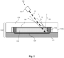
- Fig. 2 shows a principal sketch of a second embodiment of a laser-based light source 100 with a light converting device 130.
- the light converting device 130 comprises a substrate 131 which acts again as a heatsink.
- the substrate 131 further comprises a reflective structure 137 which is arranged between an e.g. heat conducting metal sheet comprised by the substrate 131 and the light converter 134.
- the reflective structure 137 is a combination of a multilayer dichroic filter being reflective in the wavelength range of the laser light 10 and the converted light 20 and a silver layer between the dichroic filter and the metal sheet.
- the light converter 134 is glued to the reflective structure 137.
- a reflective side structure 132 is deposited at the side surfaces of the light converter 134.
- the reflective side structure 132 bonds or adheres a transparent cooling element 139 either directly (direct bond between the cooling element 139 and the substrate 131) or indirectly (bonding via the light converter 134) to the substrate 131.
- the cooling element 139 comprises a support structure 139a.
- the support structure 139a is arranged to define a distance between the light entrance surface of the light converter 134 and the cooling element 139 perpendicular to the light entrance surface such that there is a decoupling structure 138 (air gap) between the light converter 134 and the cooling element 139.
- the laser 110 emits laser light 10 through the transparent cooling element 139 to the light converter 134. A part of the laser light 10 is converted by means of the light converter 134 to converted light 20 such that a mixture of reflected laser light 11 and converted light 20 is emitted through the transparent cooling element 139.
- Fig. 3 shows a principal sketch of a third embodiment of a laser-based light source 100 with a light converting device 130.
- the light converting device 130 differs from the light converting device 130 described with respect to Fig. 2 in that the support structure 139a is a separate structure.
- the light converting device 130 is further combined with an optical element 151 in order to build a light emitting element.
- the optical element 151 which is, for example a sapphire dome is bonded to the cooling element 139 by means of a bonding layer 150.
- the bonding layer 150 may be a layer of glue or adhesive which is arranged between the cooling element 139 and the optical element 151.
- the decoupling structure 138 comprises a silicone material with a refractive index which is the same or smaller than the refractive index of the material of the bonding layer 150 such that essentially all of the converted light 20 and reflected laser light 11 received by the transparent cooling element 139 leaves the transparent cooling element 139 via the bonding layer 150 in order to be collimated by means of the optical element 151.
- the optical element 151 (sapphire dome) has a bigger diameter than the light converter 134 (e.g. 5 or even 10 times more) such that essentially all reflected laser light 11 and converted laser light 20 passes the sapphire dome.
- the laser light 10 emitted by the laser 110 passes the optical element 151 (sapphire dome), the bonding layer 150, the cooling element 139 and the decoupling structure 138 before entering the light converter 134.
Landscapes
- Engineering & Computer Science (AREA)
- General Engineering & Computer Science (AREA)
- Physics & Mathematics (AREA)
- Optics & Photonics (AREA)
- General Physics & Mathematics (AREA)
- Semiconductor Lasers (AREA)
- Non-Portable Lighting Devices Or Systems Thereof (AREA)
- Optical Filters (AREA)
Claims (11)
- Dispositif de conversion de lumière (130) comprenant :- un convertisseur de lumière (134), dans lequel le convertisseur de lumière (134) est conçu pour convertir une lumière laser (10) en une lumière convertie (20), dans lequel une longueur d'onde d'émission de crête de la lumière convertie (20) se trouve dans une plage de longueur d'onde plus longue qu'une longueur d'onde d'émission de crête laser de la lumière laser (10), dans lequel le convertisseur de lumière (134) comprend une surface d'entrée de lumière, une surface de liaison opposée à la surface d'entrée de lumière et une surface latérale ;- un substrat (131) comprenant une structure réfléchissante (137), dans lequel le convertisseur de lumière (134) est agencé sur le substrat (131) pour réfléchir la lumière laser (10) et la lumière convertie (20) au moyen de la structure réfléchissante (137) ;- une structure latérale réfléchissante (132) qui est couplée optiquement à la surface latérale du convertisseur de lumière (134) pour réfléchir la lumière laser (10) et la lumière convertie (20) au moyen de la structure latérale réfléchissante (132), dans lequel la structure latérale réfléchissante (132) comprend un matériau matriciel qui est transparent dans la plage de longueur d'onde de la lumière laser (10) et la plage de longueur d'onde de la lumière convertie (20), dans laquelle le matériau matriciel comprend des particules réfléchissantes dispersées dans le matériau matriciel, dans lequel les particules réfléchissantes sont réfléchissantes dans la plage de longueur d'onde de la lumière laser (10) et la plage de longueur d'onde de la lumière convertie (20), dans lequel le matériau matriciel est disposé sur la surface latérale du convertisseur de lumière (134) ; et- un élément de refroidissement (139) fixé à la structure latérale réfléchissante (132) pour refroidir la structure latérale réfléchissante (132), dans lequel l'élément de refroidissement (139) comprend un matériau qui est transparent dans la plage de longueur d'onde de la lumière laser (10) et la plage de longueur d'onde de la lumière convertie (20), et dans lequel l'élément de refroidissement (139) est agencé dans un chemin optique de la lumière laser (10), un chemin optique de la lumière laser réfléchie (11) et un chemin optique de la lumière convertie (20), et- une structure de découplage (138), dans lequel la structure de découplage (138) est agencée entre le convertisseur de lumière (134) et l'élément de refroidissement (139), et dans lequel la structure de découplage (138) est conçue pour éviter un guidage lumineux de la lumière laser réfléchie (11) et de la lumière convertie (20) dans l'élément de refroidissement (139).
- Dispositif de conversion de lumière (130) selon la revendication 1, dans lequel la structure de découplage (138) comprend une rugosité de surface d'au moins une des surfaces du convertisseur de lumière (134) et de l'élément de refroidissement (139) se faisant face de telle sorte que moins de 5 % de ces surfaces se faisant face se touchent.
- Dispositif de conversion de lumière (130) selon la revendication 1, dans lequel la structure de découplage (138) comprend un espace d'air ou un matériau de découplage entre le convertisseur de lumière (134) et l'élément de refroidissement (139), et un indice de réfraction de l'espace d'air ou du matériau de découplage est identique ou inférieur à un indice de réfraction d'un matériau attenant à une surface de l'élément de refroidissement (139) à l'opposé d'une surface de l'élément de refroidissement (139) faisant face au convertisseur de lumière (134).
- Dispositif de conversion de lumière (130) selon l'une quelconque des revendications précédentes, dans lequel l'élément de refroidissement (139) est lié au substrat (131) au moyen du matériau matriciel.
- Dispositif de conversion de lumière (130) selon l'une quelconque des revendications précédentes dans lequel le matériau matriciel comprend un matériau de silicone et dans lequel les particules réfléchissantes comprennent de l'oxyde de titane.
- Dispositif de conversion de lumière (130) selon l'une quelconque des revendications précédentes, dans lequel l'élément de refroidissement (139) comprend une feuille de saphir.
- Dispositif de conversion de lumière (130) selon l'une quelconque des revendications précédentes, dans lequel l'élément de refroidissement (139) comprend un revêtement antireflet (140) pour réduire sa réflectivité pour la lumière laser (10) et la lumière convertie (20).
- Dispositif de conversion de lumière (130) selon l'une quelconque des revendications précédentes, dans lequel l'élément de refroidissement (139) comprend une structure de support (139a), dans lequel la structure de support (139a) est conçue pour définir une distance entre la surface d'entrée de lumière du convertisseur de lumière (134) et l'élément de refroidissement (139) perpendiculaire à la surface d'entrée de lumière.
- Élément électroluminescent comprenant le dispositif de conversion de lumière (130) selon la revendication 3, l'élément électroluminescent comprenant en outre un élément optique (151), dans lequel l'élément optique (151) est accouplé mécaniquement à l'élément de refroidissement (139) au moyen d'une couche de liaison (150), dans lequel la couche de liaison (150) a un indice de réfraction qui est identique ou supérieur à l'indice de réfraction de l'espace d'air ou de l'élément de découplage.
- Source de lumière à base de laser (100) comprenant :- le dispositif de conversion de lumière (130) selon l'une quelconque des revendications 1 à 8 ou l'élément électroluminescent selon la revendication 9, et- un laser (110), dans lequel le laser (110) est conçu pour émettre la lumière laser (10).
- Phare de véhicule comprenant au moins une source de lumière à base de laser (100) selon la revendication 10.
Applications Claiming Priority (2)
| Application Number | Priority Date | Filing Date | Title |
|---|---|---|---|
| EP16204034 | 2016-12-14 | ||
| PCT/EP2017/081910 WO2018108709A1 (fr) | 2016-12-14 | 2017-12-07 | Dispositif de conversion de lumière |
Publications (2)
| Publication Number | Publication Date |
|---|---|
| EP3555689A1 EP3555689A1 (fr) | 2019-10-23 |
| EP3555689B1 true EP3555689B1 (fr) | 2024-06-05 |
Family
ID=57749668
Family Applications (1)
| Application Number | Title | Priority Date | Filing Date |
|---|---|---|---|
| EP17818476.8A Active EP3555689B1 (fr) | 2016-12-14 | 2017-12-07 | Dispositif de conversion de lumière |
Country Status (5)
| Country | Link |
|---|---|
| US (1) | US10781987B2 (fr) |
| EP (1) | EP3555689B1 (fr) |
| JP (1) | JP6991216B2 (fr) |
| CN (1) | CN110050223B (fr) |
| WO (1) | WO2018108709A1 (fr) |
Families Citing this family (3)
| Publication number | Priority date | Publication date | Assignee | Title |
|---|---|---|---|---|
| DE102019121518A1 (de) * | 2019-08-09 | 2021-02-11 | Schott Ag | Lichtkonversions- und Beleuchtungseinrichtung |
| DE102019121508A1 (de) * | 2019-08-09 | 2021-02-11 | Schott Ag | Grundkörper für eine Lichtkonversions- oder Beleuchtungseinrichtung |
| KR102893130B1 (ko) * | 2020-12-28 | 2025-11-28 | 엘지디스플레이 주식회사 | 광변환필름 및 이를 구비한 전자장치 |
Family Cites Families (15)
| Publication number | Priority date | Publication date | Assignee | Title |
|---|---|---|---|---|
| GB0801509D0 (en) * | 2008-01-28 | 2008-03-05 | Photonstar Led Ltd | Light emitting system with optically transparent thermally conductive element |
| JP5226077B2 (ja) * | 2008-10-15 | 2013-07-03 | 株式会社小糸製作所 | 発光モジュール、発光モジュールの製造方法、および灯具ユニット |
| CN102034919A (zh) * | 2010-10-15 | 2011-04-27 | 陈林 | 高亮度大功率led及其制作方法 |
| JP5788194B2 (ja) * | 2011-03-03 | 2015-09-30 | シャープ株式会社 | 発光装置、照明装置、及び車両用前照灯 |
| JP5090549B2 (ja) * | 2011-03-08 | 2012-12-05 | シャープ株式会社 | 焼結発光体、発光装置、照明装置、車両用前照灯、及び焼結発光体の作製方法 |
| US9346395B2 (en) * | 2011-03-08 | 2016-05-24 | Sharp Kabushiki Kaisha | Light-emitting apparatus, illumination system, vehicle headlamp, projector, and method for manufacturing light-emitting apparatus |
| JP5589007B2 (ja) * | 2012-01-18 | 2014-09-10 | シャープ株式会社 | 発光装置、照明装置および車両用前照灯 |
| CN107193180B (zh) * | 2012-08-02 | 2020-07-28 | 日亚化学工业株式会社 | 波长转换装置 |
| EP3011608B1 (fr) * | 2013-06-20 | 2017-01-11 | Philips Lighting Holding B.V. | Dispositif électroluminescent |
| JP6331353B2 (ja) | 2013-07-03 | 2018-05-30 | 日亜化学工業株式会社 | 発光装置 |
| WO2015121089A1 (fr) | 2014-02-11 | 2015-08-20 | Koninklijke Philips N.V. | Élément convertisseur de longueur d'onde, module émetteur de lumière et luminaire |
| JP2015195098A (ja) * | 2014-03-31 | 2015-11-05 | ウシオ電機株式会社 | 蛍光光源装置 |
| DE102014207024A1 (de) * | 2014-04-11 | 2015-10-15 | Osram Gmbh | Leuchtvorrichtung mit Lichtquelle und beabstandetem Leuchtstoffkörper |
| JP6515716B2 (ja) * | 2014-07-18 | 2019-05-22 | 日亜化学工業株式会社 | 発光装置およびその製造方法 |
| US10260695B2 (en) * | 2015-12-23 | 2019-04-16 | Lumileds Holding B.V. | Light conversion module with improved contrast |
-
2017
- 2017-12-07 EP EP17818476.8A patent/EP3555689B1/fr active Active
- 2017-12-07 CN CN201780077641.9A patent/CN110050223B/zh active Active
- 2017-12-07 WO PCT/EP2017/081910 patent/WO2018108709A1/fr not_active Ceased
- 2017-12-07 JP JP2019531646A patent/JP6991216B2/ja active Active
- 2017-12-07 US US16/469,111 patent/US10781987B2/en active Active
Also Published As
| Publication number | Publication date |
|---|---|
| JP2020502569A (ja) | 2020-01-23 |
| JP6991216B2 (ja) | 2022-02-03 |
| US10781987B2 (en) | 2020-09-22 |
| WO2018108709A1 (fr) | 2018-06-21 |
| EP3555689A1 (fr) | 2019-10-23 |
| CN110050223B (zh) | 2022-05-24 |
| CN110050223A (zh) | 2019-07-23 |
| US20190383456A1 (en) | 2019-12-19 |
Similar Documents
| Publication | Publication Date | Title |
|---|---|---|
| US12018805B2 (en) | Light source device and lighting device | |
| JP6371201B2 (ja) | 発光モジュール及びそれを用いた発光装置 | |
| JP6056117B2 (ja) | 発光装置及び車両用灯具 | |
| JP6444837B2 (ja) | 光源装置 | |
| US10443800B2 (en) | Laser-based light source with heat conducting outcoupling dome | |
| JPWO2014203484A1 (ja) | 波長変換部材、光源、及び自動車用ヘッドランプ | |
| US11333806B2 (en) | Reliable light conversion device for laser-based light sources | |
| JP5425023B2 (ja) | 発光装置、照明装置および車両用前照灯 | |
| CN104136830A (zh) | 转换元件和发光装置 | |
| KR101917703B1 (ko) | 형광체 모듈 | |
| EP3555689B1 (fr) | Dispositif de conversion de lumière | |
| EP3309446A1 (fr) | Dispositif de conversion de lumière avec convertisseur de lumière encastré | |
| CN109751564B (zh) | 荧光体模块 | |
| US11067242B2 (en) | Phosphor module | |
| US10808903B2 (en) | Light converting device with ceramic protection layer | |
| WO2017043121A1 (fr) | Dispositif électroluminescent et dispositif d'éclairage | |
| US10969076B2 (en) | High luminance light converting device | |
| KR101917704B1 (ko) | 형광체 모듈 | |
| WO2013175752A1 (fr) | Élément de conversion de longueur d'onde, élément optique, dispositif d'émission de lumière et dispositif de projection | |
| TWM349553U (en) | Improved structure of light emitting diode |
Legal Events
| Date | Code | Title | Description |
|---|---|---|---|
| STAA | Information on the status of an ep patent application or granted ep patent |
Free format text: STATUS: UNKNOWN |
|
| STAA | Information on the status of an ep patent application or granted ep patent |
Free format text: STATUS: THE INTERNATIONAL PUBLICATION HAS BEEN MADE |
|
| PUAI | Public reference made under article 153(3) epc to a published international application that has entered the european phase |
Free format text: ORIGINAL CODE: 0009012 |
|
| STAA | Information on the status of an ep patent application or granted ep patent |
Free format text: STATUS: REQUEST FOR EXAMINATION WAS MADE |
|
| 17P | Request for examination filed |
Effective date: 20190715 |
|
| AK | Designated contracting states |
Kind code of ref document: A1 Designated state(s): AL AT BE BG CH CY CZ DE DK EE ES FI FR GB GR HR HU IE IS IT LI LT LU LV MC MK MT NL NO PL PT RO RS SE SI SK SM TR |
|
| AX | Request for extension of the european patent |
Extension state: BA ME |
|
| DAV | Request for validation of the european patent (deleted) | ||
| DAX | Request for extension of the european patent (deleted) | ||
| RAP1 | Party data changed (applicant data changed or rights of an application transferred) |
Owner name: LUMILEDS LLC |
|
| STAA | Information on the status of an ep patent application or granted ep patent |
Free format text: STATUS: EXAMINATION IS IN PROGRESS |
|
| 17Q | First examination report despatched |
Effective date: 20220303 |
|
| REG | Reference to a national code |
Ref country code: DE Ref legal event code: R079 Free format text: PREVIOUS MAIN CLASS: G02B0027090000 Ipc: F21S0045470000 Ref document number: 602017082437 Country of ref document: DE |
|
| GRAP | Despatch of communication of intention to grant a patent |
Free format text: ORIGINAL CODE: EPIDOSNIGR1 |
|
| STAA | Information on the status of an ep patent application or granted ep patent |
Free format text: STATUS: GRANT OF PATENT IS INTENDED |
|
| RIC1 | Information provided on ipc code assigned before grant |
Ipc: G02B 19/00 20060101ALI20231220BHEP Ipc: F21S 41/176 20180101ALI20231220BHEP Ipc: F21S 41/16 20180101ALI20231220BHEP Ipc: F21S 45/47 20180101AFI20231220BHEP |
|
| INTG | Intention to grant announced |
Effective date: 20240122 |
|
| GRAS | Grant fee paid |
Free format text: ORIGINAL CODE: EPIDOSNIGR3 |
|
| GRAA | (expected) grant |
Free format text: ORIGINAL CODE: 0009210 |
|
| STAA | Information on the status of an ep patent application or granted ep patent |
Free format text: STATUS: THE PATENT HAS BEEN GRANTED |
|
| AK | Designated contracting states |
Kind code of ref document: B1 Designated state(s): AL AT BE BG CH CY CZ DE DK EE ES FI FR GB GR HR HU IE IS IT LI LT LU LV MC MK MT NL NO PL PT RO RS SE SI SK SM TR |
|
| P01 | Opt-out of the competence of the unified patent court (upc) registered |
Effective date: 20240426 |
|
| REG | Reference to a national code |
Ref country code: GB Ref legal event code: FG4D |
|
| REG | Reference to a national code |
Ref country code: CH Ref legal event code: EP |
|
| REG | Reference to a national code |
Ref country code: DE Ref legal event code: R096 Ref document number: 602017082437 Country of ref document: DE |
|
| REG | Reference to a national code |
Ref country code: IE Ref legal event code: FG4D |
|
| REG | Reference to a national code |
Ref country code: LT Ref legal event code: MG9D |
|
| PG25 | Lapsed in a contracting state [announced via postgrant information from national office to epo] |
Ref country code: BG Free format text: LAPSE BECAUSE OF FAILURE TO SUBMIT A TRANSLATION OF THE DESCRIPTION OR TO PAY THE FEE WITHIN THE PRESCRIBED TIME-LIMIT Effective date: 20240605 |
|
| REG | Reference to a national code |
Ref country code: NL Ref legal event code: MP Effective date: 20240605 |
|
| PG25 | Lapsed in a contracting state [announced via postgrant information from national office to epo] |
Ref country code: FI Free format text: LAPSE BECAUSE OF FAILURE TO SUBMIT A TRANSLATION OF THE DESCRIPTION OR TO PAY THE FEE WITHIN THE PRESCRIBED TIME-LIMIT Effective date: 20240605 Ref country code: HR Free format text: LAPSE BECAUSE OF FAILURE TO SUBMIT A TRANSLATION OF THE DESCRIPTION OR TO PAY THE FEE WITHIN THE PRESCRIBED TIME-LIMIT Effective date: 20240605 |
|
| PG25 | Lapsed in a contracting state [announced via postgrant information from national office to epo] |
Ref country code: GR Free format text: LAPSE BECAUSE OF FAILURE TO SUBMIT A TRANSLATION OF THE DESCRIPTION OR TO PAY THE FEE WITHIN THE PRESCRIBED TIME-LIMIT Effective date: 20240906 |
|
| PG25 | Lapsed in a contracting state [announced via postgrant information from national office to epo] |
Ref country code: ES Free format text: LAPSE BECAUSE OF FAILURE TO SUBMIT A TRANSLATION OF THE DESCRIPTION OR TO PAY THE FEE WITHIN THE PRESCRIBED TIME-LIMIT Effective date: 20240605 |
|
| PG25 | Lapsed in a contracting state [announced via postgrant information from national office to epo] |
Ref country code: LV Free format text: LAPSE BECAUSE OF FAILURE TO SUBMIT A TRANSLATION OF THE DESCRIPTION OR TO PAY THE FEE WITHIN THE PRESCRIBED TIME-LIMIT Effective date: 20240605 |
|
| PG25 | Lapsed in a contracting state [announced via postgrant information from national office to epo] |
Ref country code: NO Free format text: LAPSE BECAUSE OF FAILURE TO SUBMIT A TRANSLATION OF THE DESCRIPTION OR TO PAY THE FEE WITHIN THE PRESCRIBED TIME-LIMIT Effective date: 20240905 Ref country code: LV Free format text: LAPSE BECAUSE OF FAILURE TO SUBMIT A TRANSLATION OF THE DESCRIPTION OR TO PAY THE FEE WITHIN THE PRESCRIBED TIME-LIMIT Effective date: 20240605 Ref country code: HR Free format text: LAPSE BECAUSE OF FAILURE TO SUBMIT A TRANSLATION OF THE DESCRIPTION OR TO PAY THE FEE WITHIN THE PRESCRIBED TIME-LIMIT Effective date: 20240605 Ref country code: GR Free format text: LAPSE BECAUSE OF FAILURE TO SUBMIT A TRANSLATION OF THE DESCRIPTION OR TO PAY THE FEE WITHIN THE PRESCRIBED TIME-LIMIT Effective date: 20240906 Ref country code: FI Free format text: LAPSE BECAUSE OF FAILURE TO SUBMIT A TRANSLATION OF THE DESCRIPTION OR TO PAY THE FEE WITHIN THE PRESCRIBED TIME-LIMIT Effective date: 20240605 Ref country code: ES Free format text: LAPSE BECAUSE OF FAILURE TO SUBMIT A TRANSLATION OF THE DESCRIPTION OR TO PAY THE FEE WITHIN THE PRESCRIBED TIME-LIMIT Effective date: 20240605 Ref country code: BG Free format text: LAPSE BECAUSE OF FAILURE TO SUBMIT A TRANSLATION OF THE DESCRIPTION OR TO PAY THE FEE WITHIN THE PRESCRIBED TIME-LIMIT Effective date: 20240605 Ref country code: RS Free format text: LAPSE BECAUSE OF FAILURE TO SUBMIT A TRANSLATION OF THE DESCRIPTION OR TO PAY THE FEE WITHIN THE PRESCRIBED TIME-LIMIT Effective date: 20240905 |
|
| PG25 | Lapsed in a contracting state [announced via postgrant information from national office to epo] |
Ref country code: NL Free format text: LAPSE BECAUSE OF FAILURE TO SUBMIT A TRANSLATION OF THE DESCRIPTION OR TO PAY THE FEE WITHIN THE PRESCRIBED TIME-LIMIT Effective date: 20240605 |
|
| REG | Reference to a national code |
Ref country code: AT Ref legal event code: MK05 Ref document number: 1692697 Country of ref document: AT Kind code of ref document: T Effective date: 20240605 |
|
| PG25 | Lapsed in a contracting state [announced via postgrant information from national office to epo] |
Ref country code: NL Free format text: LAPSE BECAUSE OF FAILURE TO SUBMIT A TRANSLATION OF THE DESCRIPTION OR TO PAY THE FEE WITHIN THE PRESCRIBED TIME-LIMIT Effective date: 20240605 |
|
| PG25 | Lapsed in a contracting state [announced via postgrant information from national office to epo] |
Ref country code: PT Free format text: LAPSE BECAUSE OF FAILURE TO SUBMIT A TRANSLATION OF THE DESCRIPTION OR TO PAY THE FEE WITHIN THE PRESCRIBED TIME-LIMIT Effective date: 20241007 |
|
| PG25 | Lapsed in a contracting state [announced via postgrant information from national office to epo] |
Ref country code: PT Free format text: LAPSE BECAUSE OF FAILURE TO SUBMIT A TRANSLATION OF THE DESCRIPTION OR TO PAY THE FEE WITHIN THE PRESCRIBED TIME-LIMIT Effective date: 20241007 |
|
| PG25 | Lapsed in a contracting state [announced via postgrant information from national office to epo] |
Ref country code: PL Free format text: LAPSE BECAUSE OF FAILURE TO SUBMIT A TRANSLATION OF THE DESCRIPTION OR TO PAY THE FEE WITHIN THE PRESCRIBED TIME-LIMIT Effective date: 20240605 |
|
| PG25 | Lapsed in a contracting state [announced via postgrant information from national office to epo] |
Ref country code: EE Free format text: LAPSE BECAUSE OF FAILURE TO SUBMIT A TRANSLATION OF THE DESCRIPTION OR TO PAY THE FEE WITHIN THE PRESCRIBED TIME-LIMIT Effective date: 20240605 |
|
| PG25 | Lapsed in a contracting state [announced via postgrant information from national office to epo] |
Ref country code: AT Free format text: LAPSE BECAUSE OF FAILURE TO SUBMIT A TRANSLATION OF THE DESCRIPTION OR TO PAY THE FEE WITHIN THE PRESCRIBED TIME-LIMIT Effective date: 20240605 Ref country code: IS Free format text: LAPSE BECAUSE OF FAILURE TO SUBMIT A TRANSLATION OF THE DESCRIPTION OR TO PAY THE FEE WITHIN THE PRESCRIBED TIME-LIMIT Effective date: 20241005 |
|
| PG25 | Lapsed in a contracting state [announced via postgrant information from national office to epo] |
Ref country code: CZ Free format text: LAPSE BECAUSE OF FAILURE TO SUBMIT A TRANSLATION OF THE DESCRIPTION OR TO PAY THE FEE WITHIN THE PRESCRIBED TIME-LIMIT Effective date: 20240605 |
|
| PG25 | Lapsed in a contracting state [announced via postgrant information from national office to epo] |
Ref country code: RO Free format text: LAPSE BECAUSE OF FAILURE TO SUBMIT A TRANSLATION OF THE DESCRIPTION OR TO PAY THE FEE WITHIN THE PRESCRIBED TIME-LIMIT Effective date: 20240605 Ref country code: SK Free format text: LAPSE BECAUSE OF FAILURE TO SUBMIT A TRANSLATION OF THE DESCRIPTION OR TO PAY THE FEE WITHIN THE PRESCRIBED TIME-LIMIT Effective date: 20240605 |
|
| PG25 | Lapsed in a contracting state [announced via postgrant information from national office to epo] |
Ref country code: SM Free format text: LAPSE BECAUSE OF FAILURE TO SUBMIT A TRANSLATION OF THE DESCRIPTION OR TO PAY THE FEE WITHIN THE PRESCRIBED TIME-LIMIT Effective date: 20240605 |
|
| PG25 | Lapsed in a contracting state [announced via postgrant information from national office to epo] |
Ref country code: SM Free format text: LAPSE BECAUSE OF FAILURE TO SUBMIT A TRANSLATION OF THE DESCRIPTION OR TO PAY THE FEE WITHIN THE PRESCRIBED TIME-LIMIT Effective date: 20240605 Ref country code: SK Free format text: LAPSE BECAUSE OF FAILURE TO SUBMIT A TRANSLATION OF THE DESCRIPTION OR TO PAY THE FEE WITHIN THE PRESCRIBED TIME-LIMIT Effective date: 20240605 Ref country code: RO Free format text: LAPSE BECAUSE OF FAILURE TO SUBMIT A TRANSLATION OF THE DESCRIPTION OR TO PAY THE FEE WITHIN THE PRESCRIBED TIME-LIMIT Effective date: 20240605 Ref country code: PL Free format text: LAPSE BECAUSE OF FAILURE TO SUBMIT A TRANSLATION OF THE DESCRIPTION OR TO PAY THE FEE WITHIN THE PRESCRIBED TIME-LIMIT Effective date: 20240605 Ref country code: IS Free format text: LAPSE BECAUSE OF FAILURE TO SUBMIT A TRANSLATION OF THE DESCRIPTION OR TO PAY THE FEE WITHIN THE PRESCRIBED TIME-LIMIT Effective date: 20241005 Ref country code: EE Free format text: LAPSE BECAUSE OF FAILURE TO SUBMIT A TRANSLATION OF THE DESCRIPTION OR TO PAY THE FEE WITHIN THE PRESCRIBED TIME-LIMIT Effective date: 20240605 Ref country code: CZ Free format text: LAPSE BECAUSE OF FAILURE TO SUBMIT A TRANSLATION OF THE DESCRIPTION OR TO PAY THE FEE WITHIN THE PRESCRIBED TIME-LIMIT Effective date: 20240605 Ref country code: AT Free format text: LAPSE BECAUSE OF FAILURE TO SUBMIT A TRANSLATION OF THE DESCRIPTION OR TO PAY THE FEE WITHIN THE PRESCRIBED TIME-LIMIT Effective date: 20240605 |
|
| PG25 | Lapsed in a contracting state [announced via postgrant information from national office to epo] |
Ref country code: IT Free format text: LAPSE BECAUSE OF FAILURE TO SUBMIT A TRANSLATION OF THE DESCRIPTION OR TO PAY THE FEE WITHIN THE PRESCRIBED TIME-LIMIT Effective date: 20240605 |
|
| REG | Reference to a national code |
Ref country code: DE Ref legal event code: R097 Ref document number: 602017082437 Country of ref document: DE |
|
| PLBE | No opposition filed within time limit |
Free format text: ORIGINAL CODE: 0009261 |
|
| STAA | Information on the status of an ep patent application or granted ep patent |
Free format text: STATUS: NO OPPOSITION FILED WITHIN TIME LIMIT |
|
| PG25 | Lapsed in a contracting state [announced via postgrant information from national office to epo] |
Ref country code: DK Free format text: LAPSE BECAUSE OF FAILURE TO SUBMIT A TRANSLATION OF THE DESCRIPTION OR TO PAY THE FEE WITHIN THE PRESCRIBED TIME-LIMIT Effective date: 20240605 |
|
| 26N | No opposition filed |
Effective date: 20250306 |
|
| PG25 | Lapsed in a contracting state [announced via postgrant information from national office to epo] |
Ref country code: MC Free format text: LAPSE BECAUSE OF FAILURE TO SUBMIT A TRANSLATION OF THE DESCRIPTION OR TO PAY THE FEE WITHIN THE PRESCRIBED TIME-LIMIT Effective date: 20240605 |
|
| REG | Reference to a national code |
Ref country code: CH Ref legal event code: PL |
|
| PG25 | Lapsed in a contracting state [announced via postgrant information from national office to epo] |
Ref country code: LU Free format text: LAPSE BECAUSE OF NON-PAYMENT OF DUE FEES Effective date: 20241207 |
|
| PG25 | Lapsed in a contracting state [announced via postgrant information from national office to epo] |
Ref country code: SE Free format text: LAPSE BECAUSE OF FAILURE TO SUBMIT A TRANSLATION OF THE DESCRIPTION OR TO PAY THE FEE WITHIN THE PRESCRIBED TIME-LIMIT Effective date: 20240605 |
|
| REG | Reference to a national code |
Ref country code: BE Ref legal event code: MM Effective date: 20241231 |
|
| PG25 | Lapsed in a contracting state [announced via postgrant information from national office to epo] |
Ref country code: BE Free format text: LAPSE BECAUSE OF NON-PAYMENT OF DUE FEES Effective date: 20241231 |
|
| PG25 | Lapsed in a contracting state [announced via postgrant information from national office to epo] |
Ref country code: CH Free format text: LAPSE BECAUSE OF NON-PAYMENT OF DUE FEES Effective date: 20241231 |
|
| PG25 | Lapsed in a contracting state [announced via postgrant information from national office to epo] |
Ref country code: IE Free format text: LAPSE BECAUSE OF NON-PAYMENT OF DUE FEES Effective date: 20241207 |
|
| PGFP | Annual fee paid to national office [announced via postgrant information from national office to epo] |
Ref country code: GB Payment date: 20251223 Year of fee payment: 9 |
|
| PGFP | Annual fee paid to national office [announced via postgrant information from national office to epo] |
Ref country code: FR Payment date: 20251230 Year of fee payment: 9 |
|
| PG25 | Lapsed in a contracting state [announced via postgrant information from national office to epo] |
Ref country code: CY Free format text: LAPSE BECAUSE OF FAILURE TO SUBMIT A TRANSLATION OF THE DESCRIPTION OR TO PAY THE FEE WITHIN THE PRESCRIBED TIME-LIMIT; INVALID AB INITIO Effective date: 20171207 |
|
| PGFP | Annual fee paid to national office [announced via postgrant information from national office to epo] |
Ref country code: DE Payment date: 20251229 Year of fee payment: 9 |