EP3556028B1 - Verfahren zur verarbeitung des dopplereffektes eines von einer sendevorrichtung an einen nicht-geosynchronen satelliten übertragenen signals - Google Patents
Verfahren zur verarbeitung des dopplereffektes eines von einer sendevorrichtung an einen nicht-geosynchronen satelliten übertragenen signals Download PDFInfo
- Publication number
- EP3556028B1 EP3556028B1 EP17825577.4A EP17825577A EP3556028B1 EP 3556028 B1 EP3556028 B1 EP 3556028B1 EP 17825577 A EP17825577 A EP 17825577A EP 3556028 B1 EP3556028 B1 EP 3556028B1
- Authority
- EP
- European Patent Office
- Prior art keywords
- signal
- frequency
- frequency shift
- satellite
- transmitted
- Prior art date
- Legal status (The legal status is an assumption and is not a legal conclusion. Google has not performed a legal analysis and makes no representation as to the accuracy of the status listed.)
- Active
Links
Images


Classifications
-
- H—ELECTRICITY
- H04—ELECTRIC COMMUNICATION TECHNIQUE
- H04B—TRANSMISSION
- H04B7/00—Radio transmission systems, i.e. using radiation field
- H04B7/14—Relay systems
- H04B7/15—Active relay systems
- H04B7/185—Space-based or airborne stations; Stations for satellite systems
- H04B7/1851—Systems using a satellite or space-based relay
- H04B7/18513—Transmission in a satellite or space-based system
-
- H—ELECTRICITY
- H04—ELECTRIC COMMUNICATION TECHNIQUE
- H04B—TRANSMISSION
- H04B7/00—Radio transmission systems, i.e. using radiation field
- H04B7/14—Relay systems
- H04B7/15—Active relay systems
- H04B7/185—Space-based or airborne stations; Stations for satellite systems
- H04B7/195—Non-synchronous stations
-
- H—ELECTRICITY
- H04—ELECTRIC COMMUNICATION TECHNIQUE
- H04L—TRANSMISSION OF DIGITAL INFORMATION, e.g. TELEGRAPHIC COMMUNICATION
- H04L7/00—Arrangements for synchronising receiver with transmitter
- H04L7/02—Speed or phase control by the received code signals, the signals containing no special synchronisation information
- H04L7/033—Speed or phase control by the received code signals, the signals containing no special synchronisation information using the transitions of the received signal to control the phase of the synchronising-signal-generating means, e.g. using a phase-locked loop
- H04L7/0331—Speed or phase control by the received code signals, the signals containing no special synchronisation information using the transitions of the received signal to control the phase of the synchronising-signal-generating means, e.g. using a phase-locked loop with a digital phase-locked loop [PLL] processing binary samples, e.g. add/subtract logic for correction of receiver clock
-
- H—ELECTRICITY
- H04—ELECTRIC COMMUNICATION TECHNIQUE
- H04W—WIRELESS COMMUNICATION NETWORKS
- H04W56/00—Synchronisation arrangements
- H04W56/0035—Synchronisation arrangements detecting errors in frequency or phase
Definitions
- the present invention belongs to the field of wireless telecommunications systems and relates more particularly to a method of transmitting a signal between at least one transmitter device and at least one satellite moving in orbit.
- the invention notably finds an application in the field of connected objects.
- ultra-narrow band wireless telecommunications systems finds a particularly advantageous application, although in no way limiting, in ultra-narrow band wireless telecommunications systems.
- ultra narrow band (“ Ultra Narrow Band ” or UNB in English literature) is meant that the instantaneous frequency spectrum of the radio signals transmitted by a transmitting device, intended for a satellite, is of lower frequency width at two kilohertz, or even less than one kilohertz.
- Such UNB wireless telecommunication systems are particularly suitable for applications of the M2M type (acronym for “ Machine-to-Machine ”) or of the “Internet of Things” type (“ Internet of Things ” or IoT in the literature. Anglo-Saxon).
- the Doppler effect which is a function of the speed of the moving object and of the angle between the speed vector of the moving object and the direction between the two objects, changes the frequency of the transmitted signals at each instant.
- the reception frequency of the signal at the start of reception is different from the reception frequency of the signal at the end of reception.
- the variation in the frequency of reception over time can also be important because, for M2M or IoT type applications, the data rate is generally low so that the duration of the signal can be long. This change in the reception frequency over time makes the detection of such signals complex at the satellite level.
- the object of the present invention is to remedy all or part of the limitations of the solutions of the prior art, in particular those described above, by proposing a solution allowing a satellite of a telecommunications system to more easily detect signals transmitted. by transmitting devices and / or reducing collisions between signals transmitted by such transmitting devices.
- the invention relates to a method of transmitting a signal by a transmitter device to a satellite moving in orbit around the Earth, said transmitter device and the satellite comprising wireless telecommunication means. wire.
- the term “transmitter device” is understood to mean any object provided with a means of telecommunication capable of transmitting a signal.
- the sending device can be for example a connected object.
- “Connected object” is understood to mean any device connected to an Internet-type data exchange computer network, which can be interrogated or controlled remotely.
- the connected object is of any type. It can be for example a weather station collecting indoor and outdoor temperature data of a home, a sensor for measuring the level of liquid or gas in a cistern or a tank, a detector of occupancy of a parking space. , a sensor for measuring the flow of people entering a building, etc.
- the connected object can also be a relay base between a connected device and a network. This relay base can act as a repeater or a buffer by storing data at transmit to the network in a computer memory of the relay base.
- the signal emitted by the transmitter device which can be precompensated during the major part of its transmission, or even preferably at each instant of its transmission, is received by the satellite without apparent Doppler effect.
- the signal is precompensated before or at the time of transmission so that the reception frequency of the carrier of the signal received by the satellite is constant.
- the time variation of the frequency shift induced by the Doppler effect can be measured by measuring the time variation of a main frequency of the heartbeat.
- the main frequency of the presence signal is representative for example of the frequency of a carrier of said presence signal, or else of the frequency a subcarrier of said presence signal, a central frequency of an instantaneous frequency spectrum of said presence signal, a minimum or maximum frequency of said instantaneous frequency spectrum, and so on.
- the temporal variation of the main frequency of the presence signal received is in principle similar to the temporal variation of the frequency shift, in particular when the presence signal is transmitted with a main frequency constant over time.
- the time variation of the main frequency can be measured directly by measuring the difference between the main frequency at two different respective times or indirectly by measuring the main frequency at at least two different respective times, and calculating the difference between the measured main frequencies.
- the analysis of the precompensated signal received by the satellite is easier to perform, since it does not require specific processing of the received signal in order to overcome the Doppler effect, de facto reducing the number of calculations required to detect and possibly demodulate the received signal.
- the precompensation takes into account only the temporal evolution of the frequency shift and not the absolute value of the frequency shift.
- the reception frequency of the carrier of the signal received is substantially constant if the carrier before precompensation is of constant frequency, but can nevertheless be offset with respect to the theoretical frequency of said carrier of said signal due to the frequency offset induced by Doppler Effect.
- the precompensation aims to obtain a frequency shift induced by the Doppler effect perceived at the satellite level as being invariant over time.
- the method of transmission may also include one or more of the following characteristics, taken in isolation or in any technically possible combination.
- the step of precompensating the subsequent temporal evolution of the frequency shift comprises a modulation of the signal to be transmitted with a frequency opposite to the subsequent temporal evolution.
- the subsequent change in time of the frequency shift is estimated by extrapolation of the time change in the frequency shift measured on the presence signal.
- the measured change over time of the frequency shift is represented by a curve whose parameters are calculated by a curve fitting method.
- the curve fitting methods are also known under the name of regression methods.
- the precompensation therefore aims to cancel not only the temporal variation of the frequency shift induced by the Doppler effect at the level of the satellite, but also to cancel the absolute value of said frequency shift at the level of said satellite.
- the precompensation also makes it possible to obtain that the frequency of the carrier of the signal received by the satellite is substantially equal to the theoretical frequency of the carrier of the signal emitted by the sending device.
- the analysis step implements a phase locked loop.
- the transmission of the presence signal is carried out continuously over a predetermined period.
- the present invention relates to a transmitter device of a wireless telecommunications system, implementing a transmission method according to any one of the embodiments of the invention.
- the sending device is a connected object.
- the present invention relates to a wireless telecommunications system comprising at least one transmitter device according to any one of the embodiments of the invention and at least one satellite moving in orbit around the Earth.
- the figure 1 schematically represents a wireless telecommunications system 100 comprising a plurality of transmitting devices 110 and a satellite 120 of a constellation of nanosatellites previously placed in orbit around the Earth.
- radio signal an electromagnetic wave propagating via wireless means, the frequencies of which are included in the traditional spectrum of radio waves (a few hertz to several hundred gigahertz).
- the transmitting devices 110 are connected objects comprising telecommunication means 111 capable of transmitting signals to the satellite 120. It should be noted that the transmitting devices 110, hereinafter referred to as objects connected 110, can also, in particular embodiments, exchange signals with each other.
- the connected objects 110 further include an electronic card 112 provided with a microprocessor capable of processing data, or even a computer memory capable of storing data before their transmission by means of signals.
- an electronic card 112 provided with a microprocessor capable of processing data, or even a computer memory capable of storing data before their transmission by means of signals.
- the signals transmitted by the connected objects 110, and / or the signals transmitted by the satellite 120 are for example ultra narrow band signals (UNB, acronym for “ Ultra Narrow Band ”).
- the UNB signals exchanged within the telecommunications system 100 comprise a carrier whose frequency is for example of the order of a hundred MHz, or even one GHz.
- the bandwidth of UNB signals is less than 2 kHz or even less than 1 kHz.
- the telecommunications means 111 connected to the electronic card 112 of said connected object 110 comprise in the present non-limiting example of the invention an antenna capable of transmitting and receiving UNB signals, a phase-locked loop and a super-feedback receiver.
- the satellite 120 is in the present example, a CubeSat type nanosatellite formed by a cubic structure ten centimeters apart. Two photovoltaic panels 121 deployed on either side of the cubic structure supply the satellite 120 with energy. The mass of the satellite 120 is approximately equal to five kilos. An antenna 122 directed towards the earth's surface makes it possible to transmit or receive UNB signals to or from connected objects 110. It should be noted that the satellite 120 is placed in an orbit of the order of five hundred kilometers around of the earth. The satellite 120 thus moves around the Earth at a speed of the order of seven kilometers per second, and performs a complete revolution around the planet in a duration of the order of ninety minutes. More generally, the satellite 120 is in non-geosynchronous orbit, for example in LEO (“ Low Earth Orbit ”) or MEO (“ Medium Earth Orbit ”) orbit.
- LEO Low Earth Orbit
- MEO Medium Earth Orbit
- the satellite 120 further comprises a beacon 125, also known by the English term “ beacon ”, transmitting a continuous UNB signal, hereinafter called a presence signal.
- the presence signal transmitted by the beacon 125 comprises for example a carrier whose frequency, at the time of transmission, is for example constant over time.
- the beacon 125 emits presence signals discontinuously, preferably at regular intervals.
- the presence signals emitted are for example of limited duration, for example of the order of a few hundred milliseconds, a few seconds, or even a few minutes.
- the connected object 110 is generally, but not limited to, in standby mode for most of the time and that it comes out of this standby mode at regular intervals to listen and / or transmit signals.
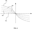
- the figure 2 represents an example of curves 150 of temporal evolution of the frequency shift undergone by the signals received by the object connected 110 from satellite 120, depending on the position of the satellite relative to the connected object.
- the figure 2 comprises five curves, each of which corresponds to a different maximum elevation angle of the satellite 120 seen by the connected object 110.
- the term maximum elevation angle also called by the English term of “ cross-track angle ”, is understood to mean the angle between the ground and the direction of the satellite 120, measured at the level of the object when the satellite 120 is as close as possible to the connected object 110.
- the abscissa of the curves 150 corresponds in the present example to the difference between the latitude of the satellite 110 and the latitude of the connected object 110.
- the satellite 120 When the maximum elevation angle is low, as in the case of the curve 150 1 , the satellite 120 is seen by the connected object 110 as being close to l 'horizon, while when the maximum angle of elevation is of the order of ninety degrees, as in the case of curve 150 2 , the connected object 110 is located substantially in line with the trajectory of satellite 120.
- the figure 3 represents in the form of a block diagram a method 200 for transmitting a signal between one of the connected objects 110 and the satellite 120 moving in orbit.
- the method 200 comprises a step 210 of reception by the connected object 110 of the presence signal transmitted by the satellite 120.
- the presence signal comprises a carrier of frequency f c_sat and at least one modulated subcarrier having a predetermined frequency deviation f S with respect to the frequency f c_sat in order to be able to differentiate the signals originating from the signals.
- beacons signals originating from connected objects 110, which do not have this particular shape or which otherwise have a predetermined frequency difference different from the frequency difference f S of the presence signal.
- the presence signal of the satellite 120 comprises information making it possible to identify the origin of the presence signal, that is to say in the present case of the beacon 125 of the satellite 120, via the presence of the modulated subcarrier exhibiting a predetermined frequency deviation f S with respect to the frequency f c_sat .
- the information identifying the presence signal can be coded in the presence signal emitted by the beacon 125 by any technique known to those skilled in the art.
- such a presence signal comprising a carrier and at least one subcarrier is of the self-synchronous type.
- the frequency shift varies over time because the angles ⁇ , E and ⁇ vary as a function of the displacement of the satellite 120 relative to the connected object 110.
- the recognition of presence signals thanks to the presence of a subcarrier exhibiting a predetermined frequency deviation with respect to the carrier is advantageously used in the case of a telecommunications network, called a hydride, comprising a plurality of connected objects and a plurality of satellites, in which a connected object can receive signals from both a satellite and another connected object.
- a telecommunications network called a hydride
- Step 210 comprises for example a sub-step 211 for detecting the signal from the beacon 125 from among a plurality of signals received.
- the super-feedback receiver included in the connected object 110 makes it possible to detect the presence signal emitted by the beacon 125 thanks to the presence of the sub-carrier in the presence signal, the frequency deviation of which from the carrier frequency of the presence signal is advantageously predetermined.
- the super-reaction receiver advantageously has very low energy consumption of the order of one hundred microwatts in active reception. Power consumption of the super-responsive receiver can be reduced by performing recurrent, non-contiguous detections through detection cycles. The increase in the latency between two consecutive detections makes it possible in particular to reduce the consumption of this receiver.
- the super-feedback receiver is advantageously insensitive to variations in frequency if the carrier and the sub-carriers vary in a similar manner, as is the case when the presence signal is subjected to the Doppler effect.
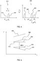
- FIG 4 An example of the result obtained by this detection mechanism is illustrated in figure 4 which comprises a curve 310 before detection and a curve 320 after detection.
- the curve 310 comprises a carrier 311 of frequency f ' c_sat and a modulated subcarrier 312 of frequency f 2 .
- the frequency difference between the carrier and the sub-carrier is equal to f S.
- the detection makes it possible to extract a signal 321 of frequency f S , a signal 322 of frequency 2f ' c_sat , a signal 323 of frequency f' c_sat + f 2 and a signal 324 of frequency 2f 2 .
- An analysis of at least one frequency shift induced by the Doppler effect on the presence signal received by the connected object 110 is carried out during a step 220 of the method 200.
- This measurement is for example carried out via the phase-locked loop included in the connected object 110 by measuring the main frequency of the presence signal received by the connected object 110 at at least two distinct instants, preferably at each instant of reception of the presence signal.
- the temporal evolution of the frequency shift ⁇ f is in fact equal to the temporal variation of the main frequency of the presence signal received.
- an estimate of a subsequent time change in the frequency shift is performed during a step 230 of the method 200.
- This subsequent time change in the frequency shift is calculated in particular in order to predict the frequency shift undergone by the signal to be transmitted by the connected object 110 during its transmission to the satellite 120.
- the subsequent temporal evolution of the frequency shift is thus estimated from a predetermined later instant. the start of transmission of the signal to be transmitted by the device 110, called the transmission time, and over a predetermined duration of this signal to be transmitted. This predetermined duration corresponds in particular to the duration of transmission of the signal.
- the subsequent temporal evolution of the shift is estimated by extrapolation of the temporal evolution of the frequency shift previously measured during step 220.
- the temporal evolution of the previously measured frequency shift can be represented by the intermediary of the theoretical curve ⁇ f (t) whose parameters are adjusted for example via curve regression methods, also called curve fitting methods (in English “Curve fitting ").
- a precompensation of the subsequent time evolution on the presence signal is performed during a step 240 of the method 200.
- the step of precompensating 240 for the subsequent change in time of the frequency shift comprises a modulation of the signal to be transmitted with a frequency opposite to the subsequent change in time.
- the precompensation can be carried out for example by means of an FM modulation (acronym for “ Frequency Modulation ”) whose modulated frequency is equal to the opposite of the variation to be precompensated.
- this FM modulation is applied over a conventional modulation for encoding the binary data contained in the signal transmitted by the connected object 110.
- the conventional modulation for encoding binary data is, in the present non-limiting example of the invention, a modulation of the DBPSK type (acronym for “ Digital Binary Phase-Shift Keying ”) comprising a rate of 100 bits per second.
- the precompensated signal is then emitted, from the time of transmission, during a step 250 of the method 200.
- the precompensation makes it possible in particular to obtain, at the time of reception by the satellite 120 of the signal emitted by the connected object 110, that the reception frequency of the signal carrier by the satellite 120 is substantially constant throughout. along the reception.
- the satellite 120 can consequently process the received signal without needing to apply to it a complex processing for correcting the temporal drift of the frequency due to the Doppler effect. It is thus possible to reuse the algorithms developed for communication between stationary objects. The computing power of the satellite is then used only to demodulate signals which apparently have not undergone a Doppler effect.
- the frequency of the carrier of the signal received by the satellite 120 is certainly constant but is generally different from the frequency of the carrier of the signal at the time of its transmission by the connected object 110.
- the analysis step further comprises a measurement of a main frequency of the presence signal and an estimate of a frequency shift induced by Doppler effect on the presence signal in function of the main frequency measured and as a function of a theoretical main frequency of the heartbeat signal.
- the theoretical frequency of the presence signal which corresponds to the frequency of the carrier when the presence signal is transmitted by the beacon 125, is in certain cases known in advance, in which case the beacon 125 transmits on a predetermined frequency corresponding for example to a previously established standard.
- the transmission frequency of the carrier is a priori unknown, the value of said transmission frequency can for example be encoded in the presence signal, and for example modulate the modulated subcarrier of said presence signal.
- the measurement of the main frequency can be carried out in particular thanks to the phase locked loop included in the connected object 110.
- the method 200 can also include a step 235 of estimating, as a function of the frequency shift estimated on the presence signal, of a frequency shift induced by the Doppler effect at the time of transmission of the signal to be transmitted, called shift subsequent frequency.
- a precompensation of the subsequent frequency shift can also be performed on the signal to be transmitted by the connected object 110, during a step 245 of the method 200, before or after the precompensation of the subsequent estimated time change of the frequency shift.
- the reception frequency of the signal carrier by the satellite 120 is substantially equal to the transmission frequency of the said signal carrier by the connected object 110, with the two precompensations by the connected object 110.
- the figure 5 illustrates the temporal evolution of the transmission frequency of a carrier of a signal 510 emitted by the connected object 110 without precompensation of the Doppler effect, of the same signal 520 transmitted with precompensation of the temporal evolution of the frequency shift and the same signal 525 transmitted with also the optional precompensation of the frequency shift.
- the transmission frequency of the carrier of the signal 510 without precompensation is constant during the transmission of the signal 510.
- the frequency of reception of the carrier of the signal 510 by the satellite 120 is shown on the diagram. figure 5 by the signal 530.
- the difference between the signal 510 and the signal 530 corresponds to the frequency shift induced by the Doppler effect on the frequency of the carrier of the signal 510 during its transmission.
- this frequency shift being a function of the speed and the relative position of the satellite 120 with respect to the connected object 110 changes over time.
- a precompensation of the temporal evolution of the frequency shift is carried out on the signal 510.
- the result obtained by this precompensation is the signal 520 which is seen by the satellite 120 at the time. of its reception as a signal 540 having a reception frequency of the constant carrier but generally different from the transmission frequency of the carrier of the signal 510.
- a pre-compensation of the frequency offset can be applied to the signal 520, so that the transmission frequency of the signal carrier corresponds to that illustrated by the signal 525.
- the signal 525 is transmitted by the connected object 110, it is received by the satellite as a signal 550 whose frequency of reception of the carrier by said satellite 120 is constant and identical to the transmission frequency of the carrier of the signal 510.
- the method 200 can also include a step of identifying the signals intended for the satellite 120 from among a plurality of signals received by the satellite 120. Since the signals intended for the satellite 120 are precompensated, they are easy to identify because they do not require prior treatment to correct the Doppler effect. This step is particularly useful in the case of a hybrid telecommunications system.
Landscapes
- Engineering & Computer Science (AREA)
- Computer Networks & Wireless Communication (AREA)
- Signal Processing (AREA)
- Physics & Mathematics (AREA)
- Astronomy & Astrophysics (AREA)
- Aviation & Aerospace Engineering (AREA)
- General Physics & Mathematics (AREA)
- Radio Relay Systems (AREA)
- Position Fixing By Use Of Radio Waves (AREA)
- Mobile Radio Communication Systems (AREA)
Claims (9)
- Verfahren (200) der Übertragung eines Signals durch eine Sendevorrichtung (110) zu einem sich im Orbit um die Erde bewegenden Satelliten (120), wobei die Sendevorrichtung (110) und der Satellit (120) Mittel zur drahtlosen Telekommunikation aufweisen,
dadurch gekennzeichnet, dass das Verfahren die folgenden Schritte umfasst:- Empfang (210) durch die Sendevorrichtung (110) eines von dem Satelliten (120) gesendeten Signals, Präsenzsignal genannt;- Analyse (220) einer durch Dopplereffekt auf das von der Sendevorrichtung empfangene Präsenzsignal (110) induzierten frequenziellen Verschiebung, wobei der Analyseschritt (220) eine Messung einer zeitlichen Entwicklung der von dem auf das Präsenzsignal ausgeübten Dopplereffekt induzierten frequenziellen Verschiebung umfasst;- Schätzung (230) in Abhängigkeit von der Analyse der von dem auf das Präsenzsignal ausgeübten Dopplereffekt induzierten frequenziellen Verschiebung einer späteren zeitlichen Entwicklung der frequenziellen Verschiebung ab einem vorher festgelegten späteren Moment des Anfangs der Sendung des von der Sendevorrichtung (110) zu sendenden Signals, genannt Sendemoment, und über eine vorher festgelegte Dauer des zu sendenden Signals;- Vorkompensierung (240) der geschätzten späteren zeitlichen Entwicklung der frequenziellen Verschiebung auf das zu sendende Signal;- Senden (250) des Signals durch die Sendevorrichtung (110) ab dem Sendemoment. - Verfahren (200) nach Anspruch 1, dadurch gekennzeichnet, dass der Schritt der Vorkompensierung (240) der späteren zeitlichen Entwicklung der frequenziellen Verschiebung eine Modulierung des zu sendenden Signals mit einer der späteren zeitlichen Entwicklung entgegengesetzten Frequenz umfasst.
- Verfahren (200) nach einem der Ansprüche 1 bis 2, dadurch gekennzeichnet, dass die spätere zeitliche Entwicklung der frequenziellen Verschiebung durch Extrapolation der zeitlichen Entwicklung der auf dem Präsenzsignal gemessenen frequenziellen Verschiebung geschätzt wird.
- Verfahren (200) nach einem der Ansprüche 1 bis 3, dadurch gekennzeichnet, dass die gemessene zeitliche Entwicklung der frequenziellen Verschiebung durch eine theoretische Kurve dargestellt wird, deren Parameter durch eine Methode zur Kurvenanpassung kalkuliert wurden.
- Verfahren (200) nach einem der Ansprüche 1 bis 4, dadurch gekennzeichnet, dass der Analyseschritt (230) eine Messung einer Hauptfrequenz des Präsenzsignals und eine Schätzung einer durch den Dopplereffekt auf das Präsenzsignal induzierten frequenziellen Verschiebung in Abhängigkeit von der gemessenen Hauptfrequenz und in Abhängigkeit von einer theoretischen Hauptfrequenz des Präsenzsignals umfasst, wobei das Verfahren gleichermaßen die folgenden Schritte umfasst:- Schätzung (235) in Abhängigkeit von der geschätzten frequenziellen Verschiebung auf dem Präsenzsignal einer durch den auf den Dopplereffekt induzierten späteren frequenziellen Verschiebung im Sendemoment des zu sendenden Signals,- Vorkompensierung (245) der späteren frequenziellen Verschiebung auf das zu sendende Signal.
- Verfahren (200) nach einem der Ansprüche 1 bis 5, dadurch gekennzeichnet, dass der Analyseschritt eine Phasenvierregelungsschleife in Gang setzt.
- Verfahren (200) nach einem der Ansprüche 1 bis 6, dadurch gekennzeichnet, dass die Sendung des Präsenzsignals für einen vorher festgelegten Zeitraum kontinuierlich ausgeführt wird.
- Sendevorrichtung (110) eines Systems (100) zur drahtlosen Telekommunikation, dadurch gekennzeichnet, dass sie ein Verfahren (200) der Übertragung nach einem der Ansprüche 1 bis 7 in Gang setzt.
- System (100) zur drahtlosen Kommunikation, dadurch gekennzeichnet, dass es wenigstens eine Sendevorrichtung (110) nach Anspruch 8 und wenigstens einen sich im Orbit um die Erde bewegenden Satelliten (120) umfasst.
Applications Claiming Priority (2)
| Application Number | Priority Date | Filing Date | Title |
|---|---|---|---|
| FR1662549A FR3060765B1 (fr) | 2016-12-15 | 2016-12-15 | Procede de traitement de l’effet doppler d’un signal transmis par un dispositif emetteur vers un satellite non geosynchrone |
| PCT/FR2017/053591 WO2018109411A1 (fr) | 2016-12-15 | 2017-12-14 | Procédé de traitement de l'effet doppler d'un signal transmis par un dispositif émetteur vers un satellite non géosynchrone |
Publications (2)
| Publication Number | Publication Date |
|---|---|
| EP3556028A1 EP3556028A1 (de) | 2019-10-23 |
| EP3556028B1 true EP3556028B1 (de) | 2020-09-02 |
Family
ID=58347581
Family Applications (1)
| Application Number | Title | Priority Date | Filing Date |
|---|---|---|---|
| EP17825577.4A Active EP3556028B1 (de) | 2016-12-15 | 2017-12-14 | Verfahren zur verarbeitung des dopplereffektes eines von einer sendevorrichtung an einen nicht-geosynchronen satelliten übertragenen signals |
Country Status (7)
| Country | Link |
|---|---|
| US (1) | US10505624B2 (de) |
| EP (1) | EP3556028B1 (de) |
| CN (1) | CN110226296B (de) |
| AU (1) | AU2017374685B2 (de) |
| FR (1) | FR3060765B1 (de) |
| RU (1) | RU2747850C2 (de) |
| WO (1) | WO2018109411A1 (de) |
Families Citing this family (7)
| Publication number | Priority date | Publication date | Assignee | Title |
|---|---|---|---|---|
| US10419063B2 (en) | 2016-12-30 | 2019-09-17 | Waviot Integrated Systems, Llc | Method and system for receiving telemetry messages over RF channel |
| CN112153732B (zh) | 2019-06-28 | 2021-12-10 | 大唐移动通信设备有限公司 | 一种多普勒频移补偿方法及设备 |
| CN113647187A (zh) | 2019-08-05 | 2021-11-12 | Oppo广东移动通信有限公司 | 通信方法和通信装置 |
| FR3105833B1 (fr) * | 2019-12-31 | 2022-06-24 | Thales Sa | Procede anti-geolocalisation d'un premier terminal de telecommunication par satellite, dispositif et programme d'ordinateur associes |
| DE102020202890B3 (de) * | 2020-03-06 | 2021-07-08 | Continental Automotive Gmbh | Verfahren und Kommunikationsvorrichtung zum Kompensieren von Doppler-Effekten in empfangenen drahtlosen Kommunikationssignalen |
| WO2021109466A1 (en) * | 2020-05-15 | 2021-06-10 | Zte Corporation | Method for synchronization |
| WO2022172658A1 (ja) | 2021-02-15 | 2022-08-18 | 古野電気株式会社 | 周波数ずれ推定装置、および、周波数ずれ推定方法 |
Family Cites Families (21)
| Publication number | Priority date | Publication date | Assignee | Title |
|---|---|---|---|---|
| FR2741159B1 (fr) * | 1995-11-14 | 1998-01-23 | Centre Nat Etd Spatiales | Systeme mondial de radiolocalisation et de radionavigation spatiale, balise, et recepteur mis en oeuvre dans un tel systeme |
| US6058306A (en) * | 1998-11-02 | 2000-05-02 | Hughes Electronics Corporation | Compensation of dynamic doppler frequency of large range in satellite communication systems |
| EP1006679A1 (de) * | 1998-12-04 | 2000-06-07 | ICO Services Ltd. | Verfahren zur Interferenzverminderung in Satelliten Kommunikation durch Verwendung Doppler Verschiebungen |
| US6308076B1 (en) * | 1999-03-23 | 2001-10-23 | Ericsson Inc. | Methods and systems for synchronization with multiple frequency offsets and known timing relationships |
| GB2368738A (en) * | 2000-07-03 | 2002-05-08 | Robert James Ely | System for space vehicle range-rate and integrated range-rate measurements |
| US6718174B2 (en) * | 2000-10-27 | 2004-04-06 | Qualcomm Incorporated | Method and apparatus for estimating velocity of a terminal in a wireless communication system |
| CA2440750C (en) * | 2001-03-15 | 2011-04-26 | Qualcomm Incorporated | Time acquisition in a wireless position determination system |
| FR2884617B1 (fr) * | 2005-04-15 | 2007-07-06 | Alstom Belgium Sa | Systeme et procede de determination de la vitesse instantanee d'un objet. |
| WO2007084682A1 (en) * | 2006-01-20 | 2007-07-26 | Atc Technologies, Llc | Systems and methods for forward link closed loop beamforming |
| IL181400A0 (en) * | 2007-02-18 | 2007-07-04 | Runcom Technologies Ltd | SATELLITE AND WiMAX COMMUNICATION SYSTEM AND METHOD |
| US8013786B2 (en) * | 2008-06-17 | 2011-09-06 | Trimble Navigation Limited | Method and communication system for limiting the functionality of an electronic device |
| CN101420253A (zh) * | 2008-12-05 | 2009-04-29 | 航天恒星科技有限公司 | 全弧段卫星遥控多普勒补偿方法 |
| SI2463682T1 (sl) * | 2010-12-07 | 2013-06-28 | Kapsch Trafficcom Ag | Postopek za ugotavljanje oddaljenosti vozila od radijskega svetilnika in ustrezen radijski svetilnik |
| JP5994773B2 (ja) * | 2011-03-25 | 2016-09-21 | 日本電気株式会社 | 送信器、受信器、送信方法、受信方法及び通信システム |
| US8451169B2 (en) * | 2011-06-10 | 2013-05-28 | Skytraq Technology, Inc. | Method and apparatus of correcting clock drift error |
| AU2013307021B2 (en) * | 2012-08-21 | 2015-11-05 | Mitsubishi Electric Corporation | Communication system, communication terminal, communication method, chip clock generation method, and orthogonal code generation method |
| GB2513302A (en) * | 2013-04-15 | 2014-10-29 | Inmarsat Global Ltd | Transmitter positioning for satellite communications |
| US9453903B2 (en) * | 2013-05-29 | 2016-09-27 | Raytheon Company | Satellite orbital determination (OD) using Doppler and Kepler orbital elements |
| US9057785B1 (en) * | 2014-05-29 | 2015-06-16 | Robert W. Lee | Radar operation with increased doppler capability |
| CN104852761B (zh) * | 2015-05-27 | 2018-08-03 | 清华大学 | 星地同步多址接入方法及利用该方法的系统 |
| CN105871495B (zh) * | 2015-12-29 | 2018-04-17 | 中国科学院国家天文台 | 一种时间同步方法、通信地面站和用户终端 |
-
2016
- 2016-12-15 FR FR1662549A patent/FR3060765B1/fr not_active Expired - Fee Related
-
2017
- 2017-12-14 RU RU2019121629A patent/RU2747850C2/ru active
- 2017-12-14 CN CN201780084696.2A patent/CN110226296B/zh not_active Expired - Fee Related
- 2017-12-14 EP EP17825577.4A patent/EP3556028B1/de active Active
- 2017-12-14 WO PCT/FR2017/053591 patent/WO2018109411A1/fr not_active Ceased
- 2017-12-14 AU AU2017374685A patent/AU2017374685B2/en not_active Ceased
- 2017-12-14 US US16/469,362 patent/US10505624B2/en active Active
Non-Patent Citations (1)
| Title |
|---|
| None * |
Also Published As
| Publication number | Publication date |
|---|---|
| EP3556028A1 (de) | 2019-10-23 |
| FR3060765B1 (fr) | 2019-01-25 |
| CN110226296A (zh) | 2019-09-10 |
| FR3060765A1 (fr) | 2018-06-22 |
| CN110226296B (zh) | 2021-10-29 |
| AU2017374685A1 (en) | 2019-07-25 |
| US20190312634A1 (en) | 2019-10-10 |
| US10505624B2 (en) | 2019-12-10 |
| RU2019121629A3 (de) | 2021-04-07 |
| AU2017374685B2 (en) | 2023-02-02 |
| WO2018109411A1 (fr) | 2018-06-21 |
| RU2019121629A (ru) | 2021-01-15 |
| RU2747850C2 (ru) | 2021-05-17 |
Similar Documents
| Publication | Publication Date | Title |
|---|---|---|
| EP3556028B1 (de) | Verfahren zur verarbeitung des dopplereffektes eines von einer sendevorrichtung an einen nicht-geosynchronen satelliten übertragenen signals | |
| EP3822653A1 (de) | Verfahren und system zur lokalisierung und satellitenkommunikation eines festen funkterminals am boden, das mindestens einen sich bewegenden satelliten verwendet | |
| FR2959571A1 (fr) | Systeme distribue de mesure de distance pour la localisation d'un satellite geostationnaire. | |
| EP2362555B1 (de) | Verfahren zur rückgewinnung eines signals aus mehreren durch einen satelliten empfangenen signalen | |
| EP3698173B1 (de) | Positionierungssystem mit gnss-signalerzeugungsvorrichtung und abstrahlendem kabel | |
| EP3026453A1 (de) | Verfahren zur erzeugung einer kartographie der sende- und empfangsabdeckung einer antenne einer bodenstation für satellitenverbindungen | |
| FR3046313A1 (fr) | Solution a repartition spatiale massive pour constellation telecom | |
| EP2587691A1 (de) | Koordiniertes Verarbeitungsverfahren von Signalen, die von Baken ausgesendet werden | |
| EP3345013B1 (de) | Nutzlast des messsatelliten eines positionierungssystems und positionierungsverfahren | |
| EP3560114B1 (de) | Optische übertragung von einem satelliten zu einem empfangsendgerät | |
| EP2715392A1 (de) | Verfahren zur ortung eines endgeräts auf der oberfläche eines reichweitengebiets mittels eines telekommunikationsnetzes mit einem mehrstrahlsatellit | |
| EP3790318B1 (de) | Interzelluläres handoververfahren | |
| EP3994804B1 (de) | Verfahren zur bestimmung mindestens eines ortes für den empfang eines rückgestreuten umgebungssignals | |
| WO2020120483A1 (fr) | Procédé de détermination de la distance entre un dispositif d'authentification et un véhicule | |
| EP3538912B1 (de) | Verfahren zur übertragung eines signals von einer sendevorrichtung an einen nicht-geosynchronen satelliten | |
| EP2392940A2 (de) | Positioniersystem eines geostationären Satelliten | |
| EP2629439B1 (de) | Verfahren zur Erzeugung eines Sende- oder Empfangsdiagramms einer Satellitenantenne | |
| EP3797313A1 (de) | Verfahren und systeme zur positions- und funkführung in nicht-kooperativen umgebungen | |
| FR3084547A1 (fr) | Methodes et systemes de radioguidage en environnements non cooperatifs | |
| EP2724179B1 (de) | Optimierung eines ortungssystems mit terrestrischen sendebasisstationen | |
| FR3027175A1 (fr) | Procede pour fournir des donnees de paquets de donnees ais recus, dispositif et programme d'ordinateur a cet effet | |
| WO2004027449A1 (fr) | Procede et dispositif de mesure de courtes distances par analyse de modulation d'une onde |
Legal Events
| Date | Code | Title | Description |
|---|---|---|---|
| STAA | Information on the status of an ep patent application or granted ep patent |
Free format text: STATUS: UNKNOWN |
|
| STAA | Information on the status of an ep patent application or granted ep patent |
Free format text: STATUS: THE INTERNATIONAL PUBLICATION HAS BEEN MADE |
|
| PUAI | Public reference made under article 153(3) epc to a published international application that has entered the european phase |
Free format text: ORIGINAL CODE: 0009012 |
|
| STAA | Information on the status of an ep patent application or granted ep patent |
Free format text: STATUS: REQUEST FOR EXAMINATION WAS MADE |
|
| 17P | Request for examination filed |
Effective date: 20190625 |
|
| AK | Designated contracting states |
Kind code of ref document: A1 Designated state(s): AL AT BE BG CH CY CZ DE DK EE ES FI FR GB GR HR HU IE IS IT LI LT LU LV MC MK MT NL NO PL PT RO RS SE SI SK SM TR |
|
| AX | Request for extension of the european patent |
Extension state: BA ME |
|
| DAV | Request for validation of the european patent (deleted) | ||
| DAX | Request for extension of the european patent (deleted) | ||
| GRAP | Despatch of communication of intention to grant a patent |
Free format text: ORIGINAL CODE: EPIDOSNIGR1 |
|
| STAA | Information on the status of an ep patent application or granted ep patent |
Free format text: STATUS: GRANT OF PATENT IS INTENDED |
|
| INTG | Intention to grant announced |
Effective date: 20200429 |
|
| GRAS | Grant fee paid |
Free format text: ORIGINAL CODE: EPIDOSNIGR3 |
|
| GRAA | (expected) grant |
Free format text: ORIGINAL CODE: 0009210 |
|
| STAA | Information on the status of an ep patent application or granted ep patent |
Free format text: STATUS: THE PATENT HAS BEEN GRANTED |
|
| AK | Designated contracting states |
Kind code of ref document: B1 Designated state(s): AL AT BE BG CH CY CZ DE DK EE ES FI FR GB GR HR HU IE IS IT LI LT LU LV MC MK MT NL NO PL PT RO RS SE SI SK SM TR |
|
| REG | Reference to a national code |
Ref country code: GB Ref legal event code: FG4D Free format text: NOT ENGLISH |
|
| REG | Reference to a national code |
Ref country code: AT Ref legal event code: REF Ref document number: 1310013 Country of ref document: AT Kind code of ref document: T Effective date: 20200915 Ref country code: CH Ref legal event code: EP |
|
| REG | Reference to a national code |
Ref country code: DE Ref legal event code: R096 Ref document number: 602017023017 Country of ref document: DE |
|
| REG | Reference to a national code |
Ref country code: IE Ref legal event code: FG4D Free format text: LANGUAGE OF EP DOCUMENT: FRENCH |
|
| REG | Reference to a national code |
Ref country code: LT Ref legal event code: MG4D |
|
| PG25 | Lapsed in a contracting state [announced via postgrant information from national office to epo] |
Ref country code: FI Free format text: LAPSE BECAUSE OF FAILURE TO SUBMIT A TRANSLATION OF THE DESCRIPTION OR TO PAY THE FEE WITHIN THE PRESCRIBED TIME-LIMIT Effective date: 20200902 Ref country code: NO Free format text: LAPSE BECAUSE OF FAILURE TO SUBMIT A TRANSLATION OF THE DESCRIPTION OR TO PAY THE FEE WITHIN THE PRESCRIBED TIME-LIMIT Effective date: 20201202 Ref country code: GR Free format text: LAPSE BECAUSE OF FAILURE TO SUBMIT A TRANSLATION OF THE DESCRIPTION OR TO PAY THE FEE WITHIN THE PRESCRIBED TIME-LIMIT Effective date: 20201203 Ref country code: SE Free format text: LAPSE BECAUSE OF FAILURE TO SUBMIT A TRANSLATION OF THE DESCRIPTION OR TO PAY THE FEE WITHIN THE PRESCRIBED TIME-LIMIT Effective date: 20200902 Ref country code: HR Free format text: LAPSE BECAUSE OF FAILURE TO SUBMIT A TRANSLATION OF THE DESCRIPTION OR TO PAY THE FEE WITHIN THE PRESCRIBED TIME-LIMIT Effective date: 20200902 Ref country code: LT Free format text: LAPSE BECAUSE OF FAILURE TO SUBMIT A TRANSLATION OF THE DESCRIPTION OR TO PAY THE FEE WITHIN THE PRESCRIBED TIME-LIMIT Effective date: 20200902 Ref country code: BG Free format text: LAPSE BECAUSE OF FAILURE TO SUBMIT A TRANSLATION OF THE DESCRIPTION OR TO PAY THE FEE WITHIN THE PRESCRIBED TIME-LIMIT Effective date: 20201202 |
|
| REG | Reference to a national code |
Ref country code: NL Ref legal event code: MP Effective date: 20200902 |
|
| REG | Reference to a national code |
Ref country code: AT Ref legal event code: MK05 Ref document number: 1310013 Country of ref document: AT Kind code of ref document: T Effective date: 20200902 |
|
| PG25 | Lapsed in a contracting state [announced via postgrant information from national office to epo] |
Ref country code: LV Free format text: LAPSE BECAUSE OF FAILURE TO SUBMIT A TRANSLATION OF THE DESCRIPTION OR TO PAY THE FEE WITHIN THE PRESCRIBED TIME-LIMIT Effective date: 20200902 Ref country code: PL Free format text: LAPSE BECAUSE OF FAILURE TO SUBMIT A TRANSLATION OF THE DESCRIPTION OR TO PAY THE FEE WITHIN THE PRESCRIBED TIME-LIMIT Effective date: 20200902 Ref country code: RS Free format text: LAPSE BECAUSE OF FAILURE TO SUBMIT A TRANSLATION OF THE DESCRIPTION OR TO PAY THE FEE WITHIN THE PRESCRIBED TIME-LIMIT Effective date: 20200902 |
|
| PG25 | Lapsed in a contracting state [announced via postgrant information from national office to epo] |
Ref country code: CZ Free format text: LAPSE BECAUSE OF FAILURE TO SUBMIT A TRANSLATION OF THE DESCRIPTION OR TO PAY THE FEE WITHIN THE PRESCRIBED TIME-LIMIT Effective date: 20200902 Ref country code: RO Free format text: LAPSE BECAUSE OF FAILURE TO SUBMIT A TRANSLATION OF THE DESCRIPTION OR TO PAY THE FEE WITHIN THE PRESCRIBED TIME-LIMIT Effective date: 20200902 Ref country code: PT Free format text: LAPSE BECAUSE OF FAILURE TO SUBMIT A TRANSLATION OF THE DESCRIPTION OR TO PAY THE FEE WITHIN THE PRESCRIBED TIME-LIMIT Effective date: 20210104 Ref country code: EE Free format text: LAPSE BECAUSE OF FAILURE TO SUBMIT A TRANSLATION OF THE DESCRIPTION OR TO PAY THE FEE WITHIN THE PRESCRIBED TIME-LIMIT Effective date: 20200902 Ref country code: SM Free format text: LAPSE BECAUSE OF FAILURE TO SUBMIT A TRANSLATION OF THE DESCRIPTION OR TO PAY THE FEE WITHIN THE PRESCRIBED TIME-LIMIT Effective date: 20200902 |
|
| PG25 | Lapsed in a contracting state [announced via postgrant information from national office to epo] |
Ref country code: ES Free format text: LAPSE BECAUSE OF FAILURE TO SUBMIT A TRANSLATION OF THE DESCRIPTION OR TO PAY THE FEE WITHIN THE PRESCRIBED TIME-LIMIT Effective date: 20200902 Ref country code: AT Free format text: LAPSE BECAUSE OF FAILURE TO SUBMIT A TRANSLATION OF THE DESCRIPTION OR TO PAY THE FEE WITHIN THE PRESCRIBED TIME-LIMIT Effective date: 20200902 Ref country code: AL Free format text: LAPSE BECAUSE OF FAILURE TO SUBMIT A TRANSLATION OF THE DESCRIPTION OR TO PAY THE FEE WITHIN THE PRESCRIBED TIME-LIMIT Effective date: 20200902 Ref country code: IS Free format text: LAPSE BECAUSE OF FAILURE TO SUBMIT A TRANSLATION OF THE DESCRIPTION OR TO PAY THE FEE WITHIN THE PRESCRIBED TIME-LIMIT Effective date: 20210102 |
|
| REG | Reference to a national code |
Ref country code: DE Ref legal event code: R097 Ref document number: 602017023017 Country of ref document: DE |
|
| PG25 | Lapsed in a contracting state [announced via postgrant information from national office to epo] |
Ref country code: SK Free format text: LAPSE BECAUSE OF FAILURE TO SUBMIT A TRANSLATION OF THE DESCRIPTION OR TO PAY THE FEE WITHIN THE PRESCRIBED TIME-LIMIT Effective date: 20200902 |
|
| PLBE | No opposition filed within time limit |
Free format text: ORIGINAL CODE: 0009261 |
|
| STAA | Information on the status of an ep patent application or granted ep patent |
Free format text: STATUS: NO OPPOSITION FILED WITHIN TIME LIMIT |
|
| REG | Reference to a national code |
Ref country code: CH Ref legal event code: PL |
|
| 26N | No opposition filed |
Effective date: 20210603 |
|
| PG25 | Lapsed in a contracting state [announced via postgrant information from national office to epo] |
Ref country code: SI Free format text: LAPSE BECAUSE OF FAILURE TO SUBMIT A TRANSLATION OF THE DESCRIPTION OR TO PAY THE FEE WITHIN THE PRESCRIBED TIME-LIMIT Effective date: 20200902 Ref country code: DK Free format text: LAPSE BECAUSE OF FAILURE TO SUBMIT A TRANSLATION OF THE DESCRIPTION OR TO PAY THE FEE WITHIN THE PRESCRIBED TIME-LIMIT Effective date: 20200902 Ref country code: MC Free format text: LAPSE BECAUSE OF FAILURE TO SUBMIT A TRANSLATION OF THE DESCRIPTION OR TO PAY THE FEE WITHIN THE PRESCRIBED TIME-LIMIT Effective date: 20200902 |
|
| REG | Reference to a national code |
Ref country code: BE Ref legal event code: MM Effective date: 20201231 |
|
| PG25 | Lapsed in a contracting state [announced via postgrant information from national office to epo] |
Ref country code: IE Free format text: LAPSE BECAUSE OF NON-PAYMENT OF DUE FEES Effective date: 20201214 Ref country code: LU Free format text: LAPSE BECAUSE OF NON-PAYMENT OF DUE FEES Effective date: 20201214 Ref country code: IT Free format text: LAPSE BECAUSE OF FAILURE TO SUBMIT A TRANSLATION OF THE DESCRIPTION OR TO PAY THE FEE WITHIN THE PRESCRIBED TIME-LIMIT Effective date: 20200902 |
|
| PG25 | Lapsed in a contracting state [announced via postgrant information from national office to epo] |
Ref country code: LI Free format text: LAPSE BECAUSE OF NON-PAYMENT OF DUE FEES Effective date: 20201231 Ref country code: CH Free format text: LAPSE BECAUSE OF NON-PAYMENT OF DUE FEES Effective date: 20201231 |
|
| PG25 | Lapsed in a contracting state [announced via postgrant information from national office to epo] |
Ref country code: TR Free format text: LAPSE BECAUSE OF FAILURE TO SUBMIT A TRANSLATION OF THE DESCRIPTION OR TO PAY THE FEE WITHIN THE PRESCRIBED TIME-LIMIT Effective date: 20200902 Ref country code: MT Free format text: LAPSE BECAUSE OF FAILURE TO SUBMIT A TRANSLATION OF THE DESCRIPTION OR TO PAY THE FEE WITHIN THE PRESCRIBED TIME-LIMIT Effective date: 20200902 Ref country code: CY Free format text: LAPSE BECAUSE OF FAILURE TO SUBMIT A TRANSLATION OF THE DESCRIPTION OR TO PAY THE FEE WITHIN THE PRESCRIBED TIME-LIMIT Effective date: 20200902 |
|
| PG25 | Lapsed in a contracting state [announced via postgrant information from national office to epo] |
Ref country code: MK Free format text: LAPSE BECAUSE OF FAILURE TO SUBMIT A TRANSLATION OF THE DESCRIPTION OR TO PAY THE FEE WITHIN THE PRESCRIBED TIME-LIMIT Effective date: 20200902 |
|
| PG25 | Lapsed in a contracting state [announced via postgrant information from national office to epo] |
Ref country code: BE Free format text: LAPSE BECAUSE OF NON-PAYMENT OF DUE FEES Effective date: 20201231 |
|
| PGFP | Annual fee paid to national office [announced via postgrant information from national office to epo] |
Ref country code: GB Payment date: 20221219 Year of fee payment: 6 Ref country code: FR Payment date: 20221223 Year of fee payment: 6 Ref country code: DE Payment date: 20221215 Year of fee payment: 6 |
|
| PG25 | Lapsed in a contracting state [announced via postgrant information from national office to epo] |
Ref country code: NL Free format text: LAPSE BECAUSE OF NON-PAYMENT OF DUE FEES Effective date: 20200923 |
|
| REG | Reference to a national code |
Ref country code: GB Ref legal event code: 732E Free format text: REGISTERED BETWEEN 20240125 AND 20240131 |
|
| REG | Reference to a national code |
Ref country code: DE Ref legal event code: R081 Ref document number: 602017023017 Country of ref document: DE Owner name: UNABIZ SAS, FR Free format text: FORMER OWNER: SIGFOX, LABEGE, FR |
|
| REG | Reference to a national code |
Ref country code: DE Ref legal event code: R119 Ref document number: 602017023017 Country of ref document: DE |
|
| GBPC | Gb: european patent ceased through non-payment of renewal fee |
Effective date: 20231214 |
|
| PG25 | Lapsed in a contracting state [announced via postgrant information from national office to epo] |
Ref country code: DE Free format text: LAPSE BECAUSE OF NON-PAYMENT OF DUE FEES Effective date: 20240702 |
|
| PG25 | Lapsed in a contracting state [announced via postgrant information from national office to epo] |
Ref country code: GB Free format text: LAPSE BECAUSE OF NON-PAYMENT OF DUE FEES Effective date: 20231214 |
|
| PG25 | Lapsed in a contracting state [announced via postgrant information from national office to epo] |
Ref country code: FR Free format text: LAPSE BECAUSE OF NON-PAYMENT OF DUE FEES Effective date: 20231231 |
|
| PG25 | Lapsed in a contracting state [announced via postgrant information from national office to epo] |
Ref country code: GB Free format text: LAPSE BECAUSE OF NON-PAYMENT OF DUE FEES Effective date: 20231214 Ref country code: FR Free format text: LAPSE BECAUSE OF NON-PAYMENT OF DUE FEES Effective date: 20231231 Ref country code: DE Free format text: LAPSE BECAUSE OF NON-PAYMENT OF DUE FEES Effective date: 20240702 |