EP3556111B1 - Mehrfachtreiberlautsprecher mit kreuzgekoppelten doppelwellensäulen - Google Patents
Mehrfachtreiberlautsprecher mit kreuzgekoppelten doppelwellensäulen Download PDFInfo
- Publication number
- EP3556111B1 EP3556111B1 EP17840464.6A EP17840464A EP3556111B1 EP 3556111 B1 EP3556111 B1 EP 3556111B1 EP 17840464 A EP17840464 A EP 17840464A EP 3556111 B1 EP3556111 B1 EP 3556111B1
- Authority
- EP
- European Patent Office
- Prior art keywords
- wave
- driver
- column
- enclosure
- exit
- Prior art date
- Legal status (The legal status is an assumption and is not a legal conclusion. Google has not performed a legal analysis and makes no representation as to the accuracy of the status listed.)
- Active
Links
Images








Classifications
-
- H—ELECTRICITY
- H04—ELECTRIC COMMUNICATION TECHNIQUE
- H04R—LOUDSPEAKERS, MICROPHONES, GRAMOPHONE PICK-UPS OR LIKE ACOUSTIC ELECTROMECHANICAL TRANSDUCERS; ELECTRIC HEARING AIDS; PUBLIC ADDRESS SYSTEMS
- H04R1/00—Details of transducers, loudspeakers or microphones
- H04R1/20—Arrangements for obtaining desired frequency or directional characteristics
- H04R1/22—Arrangements for obtaining desired frequency or directional characteristics for obtaining desired frequency characteristic only
- H04R1/28—Transducer mountings or enclosures modified by provision of mechanical or acoustic impedances, e.g. resonator, damping means
- H04R1/2807—Enclosures comprising vibrating or resonating arrangements
- H04R1/2811—Enclosures comprising vibrating or resonating arrangements for loudspeaker transducers
-
- H—ELECTRICITY
- H04—ELECTRIC COMMUNICATION TECHNIQUE
- H04R—LOUDSPEAKERS, MICROPHONES, GRAMOPHONE PICK-UPS OR LIKE ACOUSTIC ELECTROMECHANICAL TRANSDUCERS; ELECTRIC HEARING AIDS; PUBLIC ADDRESS SYSTEMS
- H04R1/00—Details of transducers, loudspeakers or microphones
- H04R1/20—Arrangements for obtaining desired frequency or directional characteristics
- H04R1/22—Arrangements for obtaining desired frequency or directional characteristics for obtaining desired frequency characteristic only
- H04R1/28—Transducer mountings or enclosures modified by provision of mechanical or acoustic impedances, e.g. resonator, damping means
- H04R1/2807—Enclosures comprising vibrating or resonating arrangements
- H04R1/2815—Enclosures comprising vibrating or resonating arrangements of the bass reflex type
- H04R1/2819—Enclosures comprising vibrating or resonating arrangements of the bass reflex type for loudspeaker transducers
-
- H—ELECTRICITY
- H04—ELECTRIC COMMUNICATION TECHNIQUE
- H04R—LOUDSPEAKERS, MICROPHONES, GRAMOPHONE PICK-UPS OR LIKE ACOUSTIC ELECTROMECHANICAL TRANSDUCERS; ELECTRIC HEARING AIDS; PUBLIC ADDRESS SYSTEMS
- H04R1/00—Details of transducers, loudspeakers or microphones
- H04R1/20—Arrangements for obtaining desired frequency or directional characteristics
- H04R1/22—Arrangements for obtaining desired frequency or directional characteristics for obtaining desired frequency characteristic only
- H04R1/28—Transducer mountings or enclosures modified by provision of mechanical or acoustic impedances, e.g. resonator, damping means
- H04R1/2807—Enclosures comprising vibrating or resonating arrangements
- H04R1/2838—Enclosures comprising vibrating or resonating arrangements of the bandpass type
- H04R1/2842—Enclosures comprising vibrating or resonating arrangements of the bandpass type for loudspeaker transducers
-
- H—ELECTRICITY
- H04—ELECTRIC COMMUNICATION TECHNIQUE
- H04R—LOUDSPEAKERS, MICROPHONES, GRAMOPHONE PICK-UPS OR LIKE ACOUSTIC ELECTROMECHANICAL TRANSDUCERS; ELECTRIC HEARING AIDS; PUBLIC ADDRESS SYSTEMS
- H04R1/00—Details of transducers, loudspeakers or microphones
- H04R1/20—Arrangements for obtaining desired frequency or directional characteristics
- H04R1/22—Arrangements for obtaining desired frequency or directional characteristics for obtaining desired frequency characteristic only
- H04R1/28—Transducer mountings or enclosures modified by provision of mechanical or acoustic impedances, e.g. resonator, damping means
- H04R1/2807—Enclosures comprising vibrating or resonating arrangements
- H04R1/2853—Enclosures comprising vibrating or resonating arrangements using an acoustic labyrinth or a transmission line
- H04R1/2857—Enclosures comprising vibrating or resonating arrangements using an acoustic labyrinth or a transmission line for loudspeaker transducers
-
- H—ELECTRICITY
- H04—ELECTRIC COMMUNICATION TECHNIQUE
- H04R—LOUDSPEAKERS, MICROPHONES, GRAMOPHONE PICK-UPS OR LIKE ACOUSTIC ELECTROMECHANICAL TRANSDUCERS; ELECTRIC HEARING AIDS; PUBLIC ADDRESS SYSTEMS
- H04R1/00—Details of transducers, loudspeakers or microphones
- H04R1/20—Arrangements for obtaining desired frequency or directional characteristics
- H04R1/22—Arrangements for obtaining desired frequency or directional characteristics for obtaining desired frequency characteristic only
- H04R1/28—Transducer mountings or enclosures modified by provision of mechanical or acoustic impedances, e.g. resonator, damping means
- H04R1/2869—Reduction of undesired resonances, i.e. standing waves within enclosure, or of undesired vibrations, i.e. of the enclosure itself
- H04R1/2892—Mountings or supports for transducers
- H04R1/2896—Mountings or supports for transducers for loudspeaker transducers
-
- H—ELECTRICITY
- H04—ELECTRIC COMMUNICATION TECHNIQUE
- H04R—LOUDSPEAKERS, MICROPHONES, GRAMOPHONE PICK-UPS OR LIKE ACOUSTIC ELECTROMECHANICAL TRANSDUCERS; ELECTRIC HEARING AIDS; PUBLIC ADDRESS SYSTEMS
- H04R2201/00—Details of transducers, loudspeakers or microphones covered by H04R1/00 but not provided for in any of its subgroups
- H04R2201/02—Details casings, cabinets or mounting therein for transducers covered by H04R1/02 but not provided for in any of its subgroups
- H04R2201/029—Manufacturing aspects of enclosures transducers
Definitions
- Bass speakers such as subwoofers or low-frequency effect (LFE) speakers typically feature acoustic suspension (sealed) enclosures or bass reflex (ported or vented) enclosures.
- LFE low-frequency effect
- enclosures These different enclosure types provide different bass-response characteristics, and basic speaker theory dictates that a bass reflex configuration will provide more extended bass response down to the -3 dB cut-off frequency (known as Fc or F 3 ) than an acoustic suspension system for a given efficiency and enclosure volume.
- Fc or F 3 the -3 dB cut-off frequency
- the diaphragm displacement required for the same acoustic output is also different for these types of enclosures.
- Embodiments may also be envisaged in which the drivers are differently oriented, such that the rear surface of the first driver radiates into the throat of the first wave-column, past the front surface of the second driver and exits out of the first wave-column mouth, and such that the rear surface of the second driver radiates into the throat of the second wave-column, past the front surface of the first driver and exits out of the second wave-column mouth.
- the wave-columns are unfolded so the waveguides operate without standing wave resonances and fold losses, providing an increase output of a certain amount (e.g., about 1.5 dB).
- the enclosure including the wave-columns and drivers can be configured into various different shapes and orientations with respect to driver location, wave-column shapes, lengths, and layouts, and the addition of external circuitry to provide additional filtering and amplification functions.
- the example enclosure design of FIG. 2 produces free flowing, lossless regenerative wave-columns.
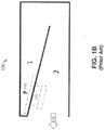
- the linear wave-column is produced without folds and may eliminate the need to use lossy absorption material in the loudspeaker that may be required in folded systems to minimize standing waves that can be formed between reflective column ends in a folded column, as in column "1" in the prior art device of FIG. 1B . It provides independent placement of primary and regenerative driver diaphragm LS1 and LS2 surfaces.
- the enclosure design 200 also provides a range of flexible configurations and parameter sets for performance enhancements, and can be packaged in small and flexible height and depth dimensions, depending on system requirements and constraints. Thus, the flexibility of enclosure containing the wave-columns and two cross-coupled drivers can be used to provide a wide variety of advantageous configurations and newly adaptive parameters.
- Example embodiments may also be envisaged in which the orientation of both drivers LS1 and LS2 are reversed compared to FIG. 2 such that instead the front sides of the drivers LS1 and LS2 radiate into the throats of the first and second chambers respectively.
- both drivers LS1 and LS2 may for example be provided with the same phase electrical connections.
- the DWC enclosure utilizes the acoustic output of all four sides of two driver (e.g., woofer driver) diaphragms in a synchronized manner to drive a pair of internal wave-columns.
- driver e.g., woofer driver
- a new type of linear transitional air-column is realized that significantly increases acoustic output capability by reducing the required diaphragm displacement of the drivers for a given sound pressure level over the passband.
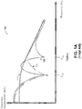
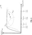
- an example DWC subwoofer using enclosure 200 with example column lengths of 3.44 meters, is explored over the most excursion critical portion of the operating range of 25 Hz to 75 Hz, as shown in the graph of FIG. 3 .
- the first side of the diaphragm of the first and second drivers, LS1 and LS2, drive the length of the wave-columns 1 and A respectively, in a manner that each wave-column operates as quarter wave tuned wave-column, with the energy within the wave-columns being magnified by the resonant loading of the enclosure to provide a more efficient acoustic impedance match to the external environment at the exit of each wave-column.
- the output of the second side of the diaphragm of driver LS 1 arrives at wave-column A beginning and is reflected back down wave-column A in phase with the first diaphragm side driver LS2 output.
- the total acoustic output is the sum of six acoustic sources from each wave-column.
- the six acoustic sources are as follows:
- FIG. 3 is a graph that illustrates the different interactive modes of the DWC enclosure, under some embodiments.
- FIG. 3 illustrates the acoustic output of the loudspeaker versus frequency for each operational mode relative to example frequencies of 25Hz, 33Hz, 50Hz, and 75Hz for the example embodiment described above.
- curve 302 represents the output after a full summation of the outputs from each driver;
- curve 304 represents the output for the odd 1 ⁇ 4-wave wave-column resonance/driver anti-resonance mode corresponding to the effective length of the wave-column;
- curve 306 represents the mutual coupling gain band mode;
- curve 308 represents the 1 ⁇ 2 wave regeneration and summation mode under an example embodiment.
- the back (+) of LS2 radiates resonant energy at every odd 1 ⁇ 4 wavelength frequency down wave-column A, past the back of LS1 and exits wave-column A as shown by line 502-A.
- the back (-) of LS 1 radiates directly out the mouth of wave-column A as shown by line 504-A. It also radiates back to down wave-column A to the throat of wave-column A, as shown by dashed line 506-A to reflect and regenerate as in phase summation with the front side of LS2 and the backside of LS1 at every odd 1 ⁇ 2 wavelength frequency.
- FIG. 7A and 7B illustrate a DWC enclosure under an embodiment in which the wave-columns are flared.
- FIG. 7A is a side view of enclosure 700 in which the wave-column 1 is shown having an increasing cross-sectional size (flared-out) from driver LS1, and wave-column A is flared out in the opposite direction.
- FIG. 7B shows an end view of the enclosure 700 as seen looking in through the exit of wave-column 1.
- line 702 represents the direct output at all frequencies enhanced at each odd 1 ⁇ 4 wavelength
- line 704 represents the direct output at all frequencies with enhanced summation at 1 ⁇ 2 wavelength
- line 706 represents the enhanced summation at each odd 1 ⁇ 2 wavelength.
- FIG. 8A and 8B illustrate a DWC enclosure under an embodiment in which the wave-columns are flared and circular in cross-section.
- FIG. 8A illustrates an end view of DWC enclosure 800 in which the enclosure is effectively fashioned into a circular tube so that the shape looking in to wave-column 1 presents a circular cross-section.
- FIG. 8B is a side view of the DWC enclosure 800 looking into end 801 showing the positive flaring configuration of the two wave-columns 1 and A.
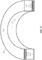
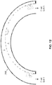
- the embodiments described so far have included loudspeaker enclosures that are straight along an axis between the throats and exits of the wave-columns.
- the enclosures may be curved, such as curved tubes or curved box section channels. The use of curved enclosures allows the sound from both wave-columns to be projected in the same or roughly the same direction. It also reduces the space requirements for the loudspeaker and allows it to be used in different environments, such as home theatre or projection room applications.
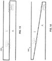
- FIG. 13 illustrates an asymmetric DWC enclosure 1300 for a uniform dual wave-column, under some embodiments; and FIG. 14 illustrates an asymmetric DWC enclosure 1400 for a flared dual wave-column, under some embodiments.
- driver LS1 is located further away from the open end of column A and from the closed end of column 1 to the inside of the enclosure so that it is a different distance to the wave-column closed end and exit than the other driver LS2.
- the embodiment shown illustrates an asymmetrical arrangement wherein LS1 may, in one example, be placed approximately 1/5 to 1 ⁇ 4 the length of the column from the closed end and/or exit of wave-column 1.
- FIG. 15 illustrates a symmetric DWC enclosure 1500 for a uniform dual wave-column, under some embodiments
- FIG. 16 illustrates a symmetric DWC enclosure 1600 for a flared dual wave-column, under some embodiments.
- the drivers LS1 and LS2 in FIGS. 15 and 16 have been equally moved toward the inside of the enclosure.
- additional drivers can be used to supplement the dual LS1 and LS2 drivers.
- FIG. 17 illustrates a uniform DWC enclosure 1700 having additional drivers denoted FR3 and FR4, under some embodiments; and
- FIG. 18 illustrates a flared DWC enclosure 1800 having the additional FR3 and FR4 drivers, under some embodiments.
- the additional drivers FR3 and FR4 are placed approximately in the middle of each wave-column, though they may be moved individually or together to different positions along their respective wave-columns.
- the flared wave-column embodiments illustrated so far, such as in FIG. 7A have shown both wave-columns positively flared such that the exit is of a larger cross-sectional area than the throat of the wave-column.
- the positive flare shortens the effective wave-column length and may enhance the output at frequencies above F B1 and may extend the bandwidth of the loudspeaker.
- the wave-columns may be negatively flared so that the exits are of a smaller cross-sectional area than the throat.
- FIG. 19 illustrates a negatively flared DWC enclosure 1900, under some embodiments. As can be seen in FIG.
- the exit area for wave-column 1 is smaller than the area of the end closes LS2 and likewise for wave-column A.
- the negative flare lengthens the effective wave-column length and may apply a soft low-pass filter to upper range frequencies. It may be desirable to include a small positive curved flare at the exit opening to minimize acoustic turbulence and audible "chuffing" at high output levels.
- the wave-columns may also be asymmetrical with respect to their lengths so that one wave-column is made longer or shorter than the other wave-column.
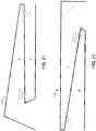
- FIG. 21 illustrates an asymmetric DWC enclosure in which the wave-column lengths are different.
- wave-column 1 is extended by adding an extender element that projects past the exit of the wave-column. This may extends the transmission length of the wave-column 1 and produces a differential wave-column length relative to the other wave-column A. This differential configuration can diversify tuning and resonances and minimize 1 wavelength cancellation and extend bandwidth.
- FIG. 21 illustrates an asymmetric DWC enclosure in which the wave-column lengths are different.
- wave-column 1 is extended by adding an extender element that projects past the exit of the wave-column. This may extends the transmission length of the wave-column 1 and produces a differential wave-column length relative to the other wave-column A. This differential configuration can diversify tuning
- FIG. 21 shows wave-column 1 extended by attaching and folding an extender element to the enclosure 2100, though any other practical means to extend the wave-column may also be used, such as in FIG. 22 , which shows an extender element attached to the enclosure 2200 and bent downward at a 90 degree angle.
- FIG. 23 illustrates a DWC enclosure 2300 in which one or more amplifiers are coupled to the drivers to alter the operating characteristics of the enclosure.
- amplifier 2302 (AMP1) is coupled to driver LS1
- amplifier 2304 (AMP2) is coupled to driver LS2.
- the amplifiers can drive their respective drivers at different levels and phases so that any phase/amplitude drive difference between the two amps can be used to optimize the summation for extended bandwidth and/or greater output over the operating range of the system.
- Other circuitry such as filters, crossovers, and the like may also be used.
- FIGS. 24 and 25 illustrate embodiments in which the DWC enclosures incorporate rear Helmholtz chambers.
- the Helmholtz chambers may be vented in front of the drivers.
- FIG. 26 illustrates a DWC enclosure 2600 having vented Helmholtz-tuned front chambers under this embodiment.
- driver LS1 is placed in a chamber 262 that is formed with a baffle or wall that has a vent 263 that vents the chamber to the wave-column 1.
- driver LS2 is placed in a chamber 264 that is formed with a baffle that has a vent 265 that vents the chamber to wave-column A.
- FIG. 30 illustrates a multi-driver DWC or driver array DWC enclosure 3000 under one embodiment.
- two loudspeaker transducer assemblies with each active loudspeaker transducer assembly including at least one transducer are located in each end portion of a wave-column.
- speakers LS1a and LS1b project sound from a front surface into wave-column A
- speakers LS2a and LS2b project sound from a front surface into wave-column 1.
- FIG. 30 illustrates a multi-driver DWC or driver array DWC enclosure 3000 under one embodiment.
- two loudspeaker transducer assemblies with each active loudspeaker transducer assembly including at least one transducer are located in each end portion of a wave-column.
- speakers LS1a and LS1b project sound from a front surface into wave-column A
- speakers LS2a and LS2b project sound from a front surface into wave-column 1.
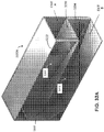
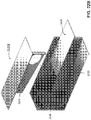
- a driver is installed in cutout 3204 close to a closed far end of a wave-column such that sound projected out of a front side of the driver is routed up in the enclosure to project out of Exit A, which is placed close to the back side of driver at cutout 3202.
- a driver in installed at cutout 3202 close to a closed far end of a wave-column such that sound projected out of a front side of the driver is routed up in the enclosure to project out of Exit B, which is placed close to the back side of driver at cutout 3204.
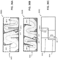
- Embodiments of the multiple fold DWC enclosure are directed to having the exit holes located at an end of the enclosure.
- the folds may be configured to allow the exit holes to be located at any surface of the enclosure, such as out of the sides or top/bottom of the enclosure.
- FIG. 36A illustrates a top view cross-section 3600A of a multiple fold DWC enclosure with a side exit for an upper section 3602, under an embodiment
- FIG. 36B illustrates a top view cross-section 3600B of a multiple fold DWC enclosure with a side exit for a lower section 3604, under an embodiment
- FIG. 36C shows a side view 3600C of the enclosure of FIGS. 36A and 36B , under an embodiment. Cutaways or holes, 3610 and 3611, provide an acoustic path between the upper and lower sections for sound transmission from drivers 3610 and 3611.
- the DWC enclosure is highly versatile with respect to configuration options. Although specific configuration parameters and characteristics are dependent on actual implementation and deployment considerations (e.g., venue size/shape, audio content, power, etc.), certain system configurations are provided as follows to give some example of possible system configurations.
- the advantages of the DWC enclosure system are increased system efficiency, increased large signal output over the operating range of the system, decreased diaphragm excursion over the operating range of the system, decreased distortion over the operating range of the system, low group delay/smooth phase response relative to other resonant systems, driver acoustical cross coupling for increased diaphragm control, optimum driver parameters allow higher moving mass and longer X-max (maximum linear excursion) construction of the dual drivers further increasing output capability by approximately 6 dB, mutual coupling coordinated to increase output and reduce diaphragm displacement at the most critical diaphragm displacement frequency range, and low profile form factor for underscreen mounting.
Landscapes
- Health & Medical Sciences (AREA)
- Otolaryngology (AREA)
- Physics & Mathematics (AREA)
- Engineering & Computer Science (AREA)
- Acoustics & Sound (AREA)
- Signal Processing (AREA)
- Audible-Bandwidth Dynamoelectric Transducers Other Than Pickups (AREA)
- Circuit For Audible Band Transducer (AREA)
Claims (16)
- Audio-Lautsprecher, umfassend:eine längliche, halbgeschlossene Struktur (200, 400, 500, 700, 800, 1000, 1100, 1200, 1300, 1400, 1500, 1600, 1700, 1800, 1900, 2000, 2100, 2200, 2300, 2400, 2500, 2600, 2700, 2800, 3000, 3100), die eine innere Schallführung (1002, 1102, 1202) aufweist, welche eine erste Wellensäule (1), die ein erstes geschlossenes Ende und einen ersten Auslass (202, 403, 801, 282) aufweist, und eine zweite Wellensäule (A) erzeugt, die ein zweites geschlossenes Ende und einen zweiten Auslass (204, 284) aufweist;einen ersten Treiber (LS1), der an einem ersten Ende der Schallführung angebracht und so ausgelegt ist, dass er resonante akustische Energie auf jeder effektiven ungeraden Viertelwellenlängen-Frequenz aus einer ersten Polaritätsseite des ersten Treibers die erste Wellensäule hinab, und aus einer zweiten Polaritätsseite des ersten Treibers direkt aus dem zweiten Auslass der zweiten Wellensäule hinaus projiziert; undeinen zweiten Treiber (LS2), der an einem zweiten Ende der Schallführung angebracht und so ausgelegt ist, dass er resonante akustische Energie auf jeder effektiven ungeraden Viertelwellenlängen-Frequenz aus einer ersten Polaritätsseite des zweiten Treibers die zweite Wellensäule hinab, und aus einer zweiten Polaritätsseite des zweiten Treibers direkt aus dem ersten Auslass der ersten Wellensäule hinaus projiziert,wobei:es sich bei den ersten Polaritätsseiten des ersten und des zweiten Treibers um Vorderseiten des ersten bzw. zweiten Treibers handelt, und beide Treiber mit gleichphasigen elektrischen Anschlüssen versehen sind; oderes sich bei den ersten Polaritätsseiten des ersten und des zweiten Treibers um Rückseiten des ersten bzw. zweiten Treibers handelt, und beide Treiber mit gleichphasigen elektrischen Anschlüssen versehen sind; oderes sich bei der ersten Polaritätsseite von einem aus dem ersten und dem zweiten Treiber um eine Vorderseite dieses Treibers handelt, während es sich bei der ersten Polaritätsseite des anderen Treibers um eine Rückseite dieses anderen Treibers handelt, und der erste und der zweite Treiber phasenverschoben zueinander verdrahtet sind.
- Lautsprecher nach Anspruch 1, wobei:der erste Treiber so ausgelegt ist, dass er resonante akustische Energie aus der ersten Polaritätsseite des ersten Treibers in das erste geschlossene Ende der ersten Wellensäule, an der zweiten Polaritätsseite des zweiten Treibers vorbei und aus dem ersten Auslass der ersten Wellensäule hinaus projiziert; undder zweite Treiber so ausgelegt ist, dass er resonante akustische Energie aus der ersten Polaritätsseite des zweiten Treibers in das zweite geschlossene Ende der zweiten Wellensäule, an der zweiten Polaritätsseite des ersten Treibers vorbei und aus dem zweiten Auslass der zweiten Wellensäule hinaus projiziert.
- Lautsprecher nach einem vorstehenden Anspruch, wobei:die zweite Polaritätsseite des zweiten Treibers akustische Energie auf einer Frequenz, die ungefähr halber Wellenlänge entspricht, die erste Wellensäule hinab projiziert, die vom ersten geschlossenen Ende der ersten Wellensäule so reflektiert wird, dass sie phasengleich mit der aus der ersten Polaritätsseite des ersten Treibers projizierten akustischen Energie regeneriert, um aus dem ersten Auslass auszutreten; unddie zweite Polaritätsseite des ersten Treibers akustische Energie die zweite Wellensäule hinab projiziert, die vom zweiten geschlossenen Ende der zweiten Wellensäule so reflektiert wird, dass sie phasengleich mit der aus der ersten Polaritätsseite des zweiten Treibers projizierten akustischen Energie regeneriert, um aus dem zweiten Auslass auszutreten.
- Lautsprecher nach einem vorstehenden Anspruch, wobei die erste und die zweite Wellensäule eines sind aus: von entlang der Längsachse gleicher und einheitlicher Querschnittsgröße, oder entlang der Längsachse aufgeweitet, indem jede Wellensäule derart aufgeweitet wird, dass sich eine Querschnittsfläche der Wellensäule am Auslass von einer Querschnittsfläche des jeweiligen geschlossenen Endes unterscheidet.
- Lautsprecher nach Anspruch 4, wobei die Aufweitung eines ist aus: nach außen aufgeweitet, um eine positive Aufweitung entlang der Längsachse zu erzeugen, derart, dass eine Querschnittsfläche am Auslass größer ist als eine Querschnittsfläche des jeweiligen geschlossenen Endes, oder nach innen aufgeweitet, um eine negative Aufweitung entlang der Längsachse zu erzeugen, derart, dass eine Querschnittsfläche am Auslass kleiner ist als eine Querschnittsfläche des jeweiligen geschlossenen Endes, oder unterschiedlich aufgeweitet, derart, dass sich ein Aufweitungsbetrag der ersten Wellensäule von einem Aufweitungsbetrag der zweiten Wellensäule unterscheidet.
- Lautsprecher nach einem vorstehenden Anspruch, wobei eine Querschnittsform der Struktur entlang der Längsachse eines ist aus einem Quadrat, einem Rechteck, einem Kreis und einem Oval, und wobei jeder aus dem ersten Treiber und dem zweiten Treiber ein Treiber-Array umfassen kann, die je zwei oder mehr Treiber aufweisen.
- Lautsprecher nach Anspruch 6, wobei die Struktur entlang einer zur Längsachse senkrecht stehenden Achse gekrümmt ist, und wobei der erste Auslass und der zweite Auslass die resonante Energie, auf die senkrechte Achse bezogen, in im Wesentlichen die gleiche Richtung projizieren.
- Lautsprecher nach einem vorstehenden Anspruch, wobei ein erstes Ende der Schallführung dem ersten geschlossenen Ende wesentlich näher liegt als dem ersten Auslass, und ein zweites Ende der Schallführung dem zweiten geschlossenen Ende wesentlich näher liegt als dem zweiten Auslass, und wobei ein Abstand vom ersten geschlossenen Ende zum ersten Ende der Schallführung eines ist aus: der gleiche wie ein Abstand zum zweiten Ende der Schallführung, und vom Abstand zum zweiten Ende der Schallführung verschieden.
- Lautsprecher nach einem vorstehenden Anspruch, wobei der Lautsprecher weiter mindestens eines umfasst aus: einem oder mehreren Verstärkerelementen, die mit jedem aus dem ersten und dem zweiten Treiber gekoppelt sind, um einen Summationseffekt der akustischen Energie zu optimieren und größeren Ausgang und erweiterte Bandbreite des Lautsprechers bereitzustellen, oder einem Paar zusätzlicher Treiber, die an jeweiligen Wänden der Struktur an einer Stelle nahe einer Mitte der Schallführung angebracht sind, wobei jeder Treiber des Paares eine jeweilige Wellensäule antreibt, um eine Niederfrequenz-Bandbreite der jeweiligen Wellensäule zu erweitern, und einer belüfteten Helmholtz-getunten Kammer in jeder Wellensäule, die durch Anordnen eines jeweiligen Treibers an einer Position gebildet wird, der einen Abschnitt der Wellensäule abdichtet, um Luftresonanzeffekte innerhalb der Kammer zu erzeugen, und wobei jede Kammer getunt werden kann, um Auslöschungseffekte zu beseitigen oder Filtereffekte der Wellensäulen bereitzustellen.
- Lautsprecher nach einem vorstehenden Anspruch, wobei mindestens eine aus der ersten und der zweiten Wellensäule eine oder mehrere Faltungen aufweist, die so ausgelegt sind, dass sie Schall innerhalb des Gehäuses so führen, dass er durch jeweilige Auslasslöcher, die sich an einem aus einem Ende des Gehäuses oder einer Seitenfläche des Gehäuses befinden, ausgeleitet wird, wobei die Auslasslöcher so ausgelegt sind, dass sie in einer vertikalen oder horizontalen Ausrichtung aneinandergrenzen oder, auf Seiten des Gehäuses bezogen, einander gegenüberliegen, und wobei eine Ausweitungsrate einer der ersten und zweiten Wellensäule uneinheitlich sein kann.
- Verfahren zum Reduzieren der Membranauslenkung und Erhöhen des Ausgangs von Treibern in einem Lautsprecher, umfassend:Übertragen von resonanter akustischer Energie aus einer ersten Polaritätsseite eines ersten Treibers (LS1) einen Hals einer ersten Wellensäule (1) hinab, an einer zweiten Polaritätsseite eines zweiten Treibers (LS2) vorbei und aus einem Auslass (202, 403, 801, 282) der ersten Wellensäule hinaus;Übertragen von resonanter akustischer Energie aus einer ersten Polaritätsseite des zweiten Treibers einen Hals einer zweiten Wellensäule (A) hinab, an einer zweiten Polaritätsseite des ersten Treibers vorbei und aus einem Auslass (204, 284) der zweiten Wellensäule hinaus; undAuslegen der ersten und der zweiten Wellensäule so, dass der erste und der zweite Treiber derart kreuzgekoppelt sind, dass bei einer effektiven Viertelwellenlängen-Frequenz eine maximale Konusauslenkung jedes Treibers minimiert und akustischer Ausgang, auf definierte Referenzwerte bezogen, maximiert wird,wobei:es sich bei den ersten Polaritätsseiten des ersten und des zweiten Treibers um Vorderseiten des ersten bzw. zweiten Treibers handelt, und beide Treiber mit gleichphasigen elektrischen Anschlüssen versehen sind; oderes sich bei den ersten Polaritätsseiten des ersten und des zweiten Treibers um Rückseiten des ersten bzw. zweiten Treibers handelt, und beide Treiber mit gleichphasigen elektrischen Anschlüssen versehen sind; oderes sich bei der ersten Polaritätsseite von einem aus dem ersten und dem zweiten Treiber um eine Vorderseite dieses Treibers handelt, während es sich bei der ersten Polaritätsseite des anderen Treibers um eine Rückseite dieses anderen Treibers handelt, und der erste und der zweite Treiber phasenverschoben zueinander verdrahtet sind.
- Verfahren nach Anspruch 11, das weiter das Auslegen der ersten und der zweiten Wellensäule derart umfasst, dass:auf ungefähr einer Halbwellenlängen-Frequenz eine Welle einer ersten Polarität des ersten Treibers mit einer Welle einer zweiten Polarität des zweiten Treibers kreuzgekoppelt wird und mit dieser gleichphasig ist, sodass der akustische Ausgang auf der ungefähr Halbwellenlängen-Frequenz erhöht, verstärkt und geglättet wird; undauf Frequenzen unterhalb einer Halbwellenlängen-Frequenz, die dem Abstand zwischen dem ersten und dem zweiten Auslass entspricht, der akustische Ausgang am ersten und dem zweiten Auslass einen Effekt wechselseitiger akustischer Kopplung erzielt, der den akustischen Ausgang intensiviert.
- Verfahren nach einem der Ansprüche 11-12, wobei die erste und die zweite Wellensäule eines sind aus: von entlang einer Längsachse gleicher und einheitlicher Querschnittsgröße zwischen einem Auslass und einem Hals der Wellensäule, oder entlang der Längsachse aufgeweitet, indem jede Wellensäule derart aufgeweitet wird, dass sich eine Querschnittsfläche des Wellensäulenauslasses von einer Querschnittsfläche eines entsprechenden Wellensäulenhalses unterscheidet.
- Verfahren nach Anspruch 13, wobei die Aufweitung eines ist aus: nach außen aufgeweitet, um eine positive Aufweitung entlang der Längsachse zu erzeugen, derart, dass eine Querschnittsfläche des Auslasses größer ist als eine Querschnittsfläche des entsprechenden Halses, oder nach innen aufgeweitet, um eine negative Aufweitung entlang der Längsachse zu erzeugen, derart, dass eine Querschnittsfläche des Auslasses kleiner ist als eine Querschnittsfläche des entsprechenden Halses, oder unterschiedlich aufgeweitet, derart, dass sich ein Aufweitungsbetrag der ersten Wellensäule von einem Aufweitungsbetrag der zweiten Wellensäule unterscheidet.
- Verfahren nach einem der Ansprüche 11 bis 14, wobei eine Querschnittsform der Struktur entlang der Längsachse eines aus einem Quadrat, einem Rechteck, einem Kreis und einem Oval ist.
- Verfahren nach Anspruch 15, wobei die Struktur entlang einer zur Längsachse senkrecht stehenden Achse gekrümmt ist, und wobei der erste Auslass und der zweite Auslass die akustische Energie, auf die senkrechte Achse bezogen, in im Wesentlichen die gleiche Richtung projizieren.
Applications Claiming Priority (3)
| Application Number | Priority Date | Filing Date | Title |
|---|---|---|---|
| US201662433917P | 2016-12-14 | 2016-12-14 | |
| EP16204050 | 2016-12-14 | ||
| PCT/US2017/066473 WO2018112231A1 (en) | 2016-12-14 | 2017-12-14 | Multi-driver loudspeaker with cross-coupled dual wave-columns |
Publications (2)
| Publication Number | Publication Date |
|---|---|
| EP3556111A1 EP3556111A1 (de) | 2019-10-23 |
| EP3556111B1 true EP3556111B1 (de) | 2021-10-06 |
Family
ID=61187803
Family Applications (1)
| Application Number | Title | Priority Date | Filing Date |
|---|---|---|---|
| EP17840464.6A Active EP3556111B1 (de) | 2016-12-14 | 2017-12-14 | Mehrfachtreiberlautsprecher mit kreuzgekoppelten doppelwellensäulen |
Country Status (3)
| Country | Link |
|---|---|
| US (1) | US10812895B2 (de) |
| EP (1) | EP3556111B1 (de) |
| CN (1) | CN110089128B (de) |
Families Citing this family (3)
| Publication number | Priority date | Publication date | Assignee | Title |
|---|---|---|---|---|
| US11606633B2 (en) * | 2019-12-10 | 2023-03-14 | Apple Inc. | Speaker assembly |
| US11917361B2 (en) * | 2020-08-12 | 2024-02-27 | Michael Levy | Loudspeaker |
| US12439201B2 (en) | 2021-04-14 | 2025-10-07 | Dolby Laboratories Licensing Corporation | Narrow aperture waveguide loudspeaker for use with flat panel display devices |
Family Cites Families (25)
| Publication number | Priority date | Publication date | Assignee | Title |
|---|---|---|---|---|
| US3022377A (en) | 1956-10-29 | 1962-02-20 | Philco Corp | Sound reproducing system |
| US3136383A (en) | 1963-03-15 | 1964-06-09 | Herbert J Hopkins | Duplex loud speaker sound box system |
| US3608665A (en) | 1969-09-16 | 1971-09-28 | Mohamed B A Drisi | Sound-reproducing structure |
| US4875546A (en) | 1988-06-02 | 1989-10-24 | Teledyne Industries, Inc. | Loudspeaker with acoustic band-pass filter |
| US5109416A (en) | 1990-09-28 | 1992-04-28 | Croft James J | Dipole speaker for producing ambience sound |
| JP3063214B2 (ja) | 1991-05-02 | 2000-07-12 | 松下電器産業株式会社 | スピーカ装置およびそれを用いたテレビジョン受像機 |
| JP3410206B2 (ja) | 1994-04-18 | 2003-05-26 | パイオニア株式会社 | スピーカ装置 |
| US6411721B1 (en) * | 1997-12-19 | 2002-06-25 | William E. Spindler | Audio speaker with harmonic enclosure |
| US6389146B1 (en) * | 2000-02-17 | 2002-05-14 | American Technology Corporation | Acoustically asymmetric bandpass loudspeaker with multiple acoustic filters |
| JP3742963B2 (ja) | 1999-07-02 | 2006-02-08 | 株式会社ケンウッド | スピーカ装置、および音響再生方法 |
| CN1153505C (zh) | 2000-04-15 | 2004-06-09 | 王天资 | 腔式频率下限低失真小的交叉互补音箱 |
| US7426280B2 (en) * | 2001-01-02 | 2008-09-16 | Bose Corporation | Electroacoustic waveguide transducing |
| JP2002330486A (ja) | 2001-04-27 | 2002-11-15 | Sanyo Electric Co Ltd | スピーカ装置 |
| US7392880B2 (en) | 2002-04-02 | 2008-07-01 | Gibson Guitar Corp. | Dual range horn with acoustic crossover |
| US7551749B2 (en) * | 2002-08-23 | 2009-06-23 | Bose Corporation | Baffle vibration reducing |
| US7184098B2 (en) * | 2004-02-19 | 2007-02-27 | Spatialight, Inc. | Cyclic data signal averaging system and method for use in video display systems |
| EP1571873A1 (de) | 2004-03-01 | 2005-09-07 | Thomson Licensing S.A. | Akustisches System |
| US7277552B2 (en) | 2004-08-09 | 2007-10-02 | Graber Curtis E | Increased LF spectrum power density loudspeaker system |
| US8014545B2 (en) * | 2006-12-18 | 2011-09-06 | Dei Headquarters, Inc. | Ceiling or wall-mounted loudspeaker system with anti-diffraction wave launch device |
| US8351629B2 (en) | 2008-02-21 | 2013-01-08 | Robert Preston Parker | Waveguide electroacoustical transducing |
| US20110176701A1 (en) | 2010-01-16 | 2011-07-21 | Collins William E | Autoaugmented Speaker Port |
| CN201904889U (zh) | 2010-11-24 | 2011-07-20 | 东莞市达硕科技有限公司 | 一种音箱结构 |
| EP2974356B1 (de) | 2013-03-13 | 2020-05-06 | THX Ltd | Flacher lautsprecher |
| US9247342B2 (en) * | 2013-05-14 | 2016-01-26 | James J. Croft, III | Loudspeaker enclosure system with signal processor for enhanced perception of low frequency output |
| CN203734819U (zh) | 2014-03-11 | 2014-07-23 | 韦幸召 | 球对称推挽式超高保真音箱 |
-
2017
- 2017-12-14 US US16/465,820 patent/US10812895B2/en active Active
- 2017-12-14 EP EP17840464.6A patent/EP3556111B1/de active Active
- 2017-12-14 CN CN201780077093.XA patent/CN110089128B/zh active Active
Non-Patent Citations (1)
| Title |
|---|
| None * |
Also Published As
| Publication number | Publication date |
|---|---|
| US10812895B2 (en) | 2020-10-20 |
| CN110089128B (zh) | 2020-08-25 |
| US20200029150A1 (en) | 2020-01-23 |
| CN110089128A (zh) | 2019-08-02 |
| EP3556111A1 (de) | 2019-10-23 |
Similar Documents
| Publication | Publication Date | Title |
|---|---|---|
| JP5405598B2 (ja) | スピーカ | |
| CA1226820A (en) | Pressure wave transducing | |
| JP4125291B2 (ja) | 音源からの音の品質を向上させるための装置 | |
| US5875255A (en) | High power electroacoustic speaker system having wide band frequency response | |
| US7207413B2 (en) | Closed loop embedded audio transmission line technology for loudspeaker enclosures and systems | |
| JPH02260899A (ja) | スピーカシステム | |
| US4593784A (en) | Loudspeaker enclosure | |
| JPH0514988A (ja) | ラウドスピーカ・システム | |
| US20050087392A1 (en) | Loudspeaker enclosure | |
| US20150003657A1 (en) | Inverse horn loudspeakers | |
| CN105407431A (zh) | 具有改良的指向行为和降低的声干涉的扬声器 | |
| EP1188353A1 (de) | Bandpasslautsprecher | |
| US7506721B2 (en) | Convertible folded horn enclosure | |
| EP3556111B1 (de) | Mehrfachtreiberlautsprecher mit kreuzgekoppelten doppelwellensäulen | |
| US7668331B2 (en) | Fidelity speaker | |
| US20060078136A1 (en) | Chamber-loaded augmented passive radiator | |
| WO2022102360A1 (ja) | 音響装置 | |
| CN103858443B (zh) | 扬声器 | |
| WO2018112231A1 (en) | Multi-driver loudspeaker with cross-coupled dual wave-columns | |
| US8085968B2 (en) | Resonating cone transducer | |
| US20050175206A1 (en) | Loudspeaker assembly having a folded bifurcated vent tube | |
| CN112544087B (zh) | 具有多平面、嵌套、折叠喇叭的扬声器系统 | |
| US20200068293A1 (en) | Bass Loud Speaker for Corner Placement | |
| US8259981B2 (en) | Horn-loaded acoustic line source | |
| JP2010193228A (ja) | スピーカーシステム |
Legal Events
| Date | Code | Title | Description |
|---|---|---|---|
| STAA | Information on the status of an ep patent application or granted ep patent |
Free format text: STATUS: UNKNOWN |
|
| STAA | Information on the status of an ep patent application or granted ep patent |
Free format text: STATUS: THE INTERNATIONAL PUBLICATION HAS BEEN MADE |
|
| PUAI | Public reference made under article 153(3) epc to a published international application that has entered the european phase |
Free format text: ORIGINAL CODE: 0009012 |
|
| STAA | Information on the status of an ep patent application or granted ep patent |
Free format text: STATUS: REQUEST FOR EXAMINATION WAS MADE |
|
| 17P | Request for examination filed |
Effective date: 20190715 |
|
| AK | Designated contracting states |
Kind code of ref document: A1 Designated state(s): AL AT BE BG CH CY CZ DE DK EE ES FI FR GB GR HR HU IE IS IT LI LT LU LV MC MK MT NL NO PL PT RO RS SE SI SK SM TR |
|
| AX | Request for extension of the european patent |
Extension state: BA ME |
|
| DAV | Request for validation of the european patent (deleted) | ||
| DAX | Request for extension of the european patent (deleted) | ||
| GRAP | Despatch of communication of intention to grant a patent |
Free format text: ORIGINAL CODE: EPIDOSNIGR1 |
|
| STAA | Information on the status of an ep patent application or granted ep patent |
Free format text: STATUS: GRANT OF PATENT IS INTENDED |
|
| INTG | Intention to grant announced |
Effective date: 20201119 |
|
| GRAJ | Information related to disapproval of communication of intention to grant by the applicant or resumption of examination proceedings by the epo deleted |
Free format text: ORIGINAL CODE: EPIDOSDIGR1 |
|
| STAA | Information on the status of an ep patent application or granted ep patent |
Free format text: STATUS: REQUEST FOR EXAMINATION WAS MADE |
|
| INTC | Intention to grant announced (deleted) | ||
| GRAP | Despatch of communication of intention to grant a patent |
Free format text: ORIGINAL CODE: EPIDOSNIGR1 |
|
| STAA | Information on the status of an ep patent application or granted ep patent |
Free format text: STATUS: GRANT OF PATENT IS INTENDED |
|
| INTG | Intention to grant announced |
Effective date: 20210504 |
|
| GRAS | Grant fee paid |
Free format text: ORIGINAL CODE: EPIDOSNIGR3 |
|
| GRAA | (expected) grant |
Free format text: ORIGINAL CODE: 0009210 |
|
| STAA | Information on the status of an ep patent application or granted ep patent |
Free format text: STATUS: THE PATENT HAS BEEN GRANTED |
|
| AK | Designated contracting states |
Kind code of ref document: B1 Designated state(s): AL AT BE BG CH CY CZ DE DK EE ES FI FR GB GR HR HU IE IS IT LI LT LU LV MC MK MT NL NO PL PT RO RS SE SI SK SM TR |
|
| REG | Reference to a national code |
Ref country code: GB Ref legal event code: FG4D |
|
| REG | Reference to a national code |
Ref country code: CH Ref legal event code: EP Ref country code: AT Ref legal event code: REF Ref document number: 1437272 Country of ref document: AT Kind code of ref document: T Effective date: 20211015 |
|
| REG | Reference to a national code |
Ref country code: DE Ref legal event code: R096 Ref document number: 602017047303 Country of ref document: DE |
|
| REG | Reference to a national code |
Ref country code: IE Ref legal event code: FG4D |
|
| REG | Reference to a national code |
Ref country code: LT Ref legal event code: MG9D |
|
| REG | Reference to a national code |
Ref country code: NL Ref legal event code: MP Effective date: 20211006 |
|
| REG | Reference to a national code |
Ref country code: AT Ref legal event code: MK05 Ref document number: 1437272 Country of ref document: AT Kind code of ref document: T Effective date: 20211006 |
|
| PG25 | Lapsed in a contracting state [announced via postgrant information from national office to epo] |
Ref country code: RS Free format text: LAPSE BECAUSE OF FAILURE TO SUBMIT A TRANSLATION OF THE DESCRIPTION OR TO PAY THE FEE WITHIN THE PRESCRIBED TIME-LIMIT Effective date: 20211006 Ref country code: LT Free format text: LAPSE BECAUSE OF FAILURE TO SUBMIT A TRANSLATION OF THE DESCRIPTION OR TO PAY THE FEE WITHIN THE PRESCRIBED TIME-LIMIT Effective date: 20211006 Ref country code: FI Free format text: LAPSE BECAUSE OF FAILURE TO SUBMIT A TRANSLATION OF THE DESCRIPTION OR TO PAY THE FEE WITHIN THE PRESCRIBED TIME-LIMIT Effective date: 20211006 Ref country code: BG Free format text: LAPSE BECAUSE OF FAILURE TO SUBMIT A TRANSLATION OF THE DESCRIPTION OR TO PAY THE FEE WITHIN THE PRESCRIBED TIME-LIMIT Effective date: 20220106 Ref country code: AT Free format text: LAPSE BECAUSE OF FAILURE TO SUBMIT A TRANSLATION OF THE DESCRIPTION OR TO PAY THE FEE WITHIN THE PRESCRIBED TIME-LIMIT Effective date: 20211006 |
|
| PG25 | Lapsed in a contracting state [announced via postgrant information from national office to epo] |
Ref country code: IS Free format text: LAPSE BECAUSE OF FAILURE TO SUBMIT A TRANSLATION OF THE DESCRIPTION OR TO PAY THE FEE WITHIN THE PRESCRIBED TIME-LIMIT Effective date: 20220206 Ref country code: SE Free format text: LAPSE BECAUSE OF FAILURE TO SUBMIT A TRANSLATION OF THE DESCRIPTION OR TO PAY THE FEE WITHIN THE PRESCRIBED TIME-LIMIT Effective date: 20211006 Ref country code: PT Free format text: LAPSE BECAUSE OF FAILURE TO SUBMIT A TRANSLATION OF THE DESCRIPTION OR TO PAY THE FEE WITHIN THE PRESCRIBED TIME-LIMIT Effective date: 20220207 Ref country code: PL Free format text: LAPSE BECAUSE OF FAILURE TO SUBMIT A TRANSLATION OF THE DESCRIPTION OR TO PAY THE FEE WITHIN THE PRESCRIBED TIME-LIMIT Effective date: 20211006 Ref country code: NO Free format text: LAPSE BECAUSE OF FAILURE TO SUBMIT A TRANSLATION OF THE DESCRIPTION OR TO PAY THE FEE WITHIN THE PRESCRIBED TIME-LIMIT Effective date: 20220106 Ref country code: NL Free format text: LAPSE BECAUSE OF FAILURE TO SUBMIT A TRANSLATION OF THE DESCRIPTION OR TO PAY THE FEE WITHIN THE PRESCRIBED TIME-LIMIT Effective date: 20211006 Ref country code: LV Free format text: LAPSE BECAUSE OF FAILURE TO SUBMIT A TRANSLATION OF THE DESCRIPTION OR TO PAY THE FEE WITHIN THE PRESCRIBED TIME-LIMIT Effective date: 20211006 Ref country code: HR Free format text: LAPSE BECAUSE OF FAILURE TO SUBMIT A TRANSLATION OF THE DESCRIPTION OR TO PAY THE FEE WITHIN THE PRESCRIBED TIME-LIMIT Effective date: 20211006 Ref country code: GR Free format text: LAPSE BECAUSE OF FAILURE TO SUBMIT A TRANSLATION OF THE DESCRIPTION OR TO PAY THE FEE WITHIN THE PRESCRIBED TIME-LIMIT Effective date: 20220107 Ref country code: ES Free format text: LAPSE BECAUSE OF FAILURE TO SUBMIT A TRANSLATION OF THE DESCRIPTION OR TO PAY THE FEE WITHIN THE PRESCRIBED TIME-LIMIT Effective date: 20211006 |
|
| REG | Reference to a national code |
Ref country code: DE Ref legal event code: R097 Ref document number: 602017047303 Country of ref document: DE |
|
| PG25 | Lapsed in a contracting state [announced via postgrant information from national office to epo] |
Ref country code: SM Free format text: LAPSE BECAUSE OF FAILURE TO SUBMIT A TRANSLATION OF THE DESCRIPTION OR TO PAY THE FEE WITHIN THE PRESCRIBED TIME-LIMIT Effective date: 20211006 Ref country code: SK Free format text: LAPSE BECAUSE OF FAILURE TO SUBMIT A TRANSLATION OF THE DESCRIPTION OR TO PAY THE FEE WITHIN THE PRESCRIBED TIME-LIMIT Effective date: 20211006 Ref country code: RO Free format text: LAPSE BECAUSE OF FAILURE TO SUBMIT A TRANSLATION OF THE DESCRIPTION OR TO PAY THE FEE WITHIN THE PRESCRIBED TIME-LIMIT Effective date: 20211006 Ref country code: MC Free format text: LAPSE BECAUSE OF FAILURE TO SUBMIT A TRANSLATION OF THE DESCRIPTION OR TO PAY THE FEE WITHIN THE PRESCRIBED TIME-LIMIT Effective date: 20211006 Ref country code: EE Free format text: LAPSE BECAUSE OF FAILURE TO SUBMIT A TRANSLATION OF THE DESCRIPTION OR TO PAY THE FEE WITHIN THE PRESCRIBED TIME-LIMIT Effective date: 20211006 Ref country code: DK Free format text: LAPSE BECAUSE OF FAILURE TO SUBMIT A TRANSLATION OF THE DESCRIPTION OR TO PAY THE FEE WITHIN THE PRESCRIBED TIME-LIMIT Effective date: 20211006 Ref country code: CZ Free format text: LAPSE BECAUSE OF FAILURE TO SUBMIT A TRANSLATION OF THE DESCRIPTION OR TO PAY THE FEE WITHIN THE PRESCRIBED TIME-LIMIT Effective date: 20211006 |
|
| REG | Reference to a national code |
Ref country code: CH Ref legal event code: PL |
|
| PLBE | No opposition filed within time limit |
Free format text: ORIGINAL CODE: 0009261 |
|
| STAA | Information on the status of an ep patent application or granted ep patent |
Free format text: STATUS: NO OPPOSITION FILED WITHIN TIME LIMIT |
|
| 26N | No opposition filed |
Effective date: 20220707 |
|
| REG | Reference to a national code |
Ref country code: BE Ref legal event code: MM Effective date: 20211231 |
|
| PG25 | Lapsed in a contracting state [announced via postgrant information from national office to epo] |
Ref country code: LU Free format text: LAPSE BECAUSE OF NON-PAYMENT OF DUE FEES Effective date: 20211214 Ref country code: IE Free format text: LAPSE BECAUSE OF NON-PAYMENT OF DUE FEES Effective date: 20211214 Ref country code: AL Free format text: LAPSE BECAUSE OF FAILURE TO SUBMIT A TRANSLATION OF THE DESCRIPTION OR TO PAY THE FEE WITHIN THE PRESCRIBED TIME-LIMIT Effective date: 20211006 |
|
| PG25 | Lapsed in a contracting state [announced via postgrant information from national office to epo] |
Ref country code: SI Free format text: LAPSE BECAUSE OF FAILURE TO SUBMIT A TRANSLATION OF THE DESCRIPTION OR TO PAY THE FEE WITHIN THE PRESCRIBED TIME-LIMIT Effective date: 20211006 Ref country code: BE Free format text: LAPSE BECAUSE OF NON-PAYMENT OF DUE FEES Effective date: 20211231 |
|
| PG25 | Lapsed in a contracting state [announced via postgrant information from national office to epo] |
Ref country code: LI Free format text: LAPSE BECAUSE OF NON-PAYMENT OF DUE FEES Effective date: 20211231 Ref country code: CH Free format text: LAPSE BECAUSE OF NON-PAYMENT OF DUE FEES Effective date: 20211231 |
|
| PG25 | Lapsed in a contracting state [announced via postgrant information from national office to epo] |
Ref country code: IT Free format text: LAPSE BECAUSE OF FAILURE TO SUBMIT A TRANSLATION OF THE DESCRIPTION OR TO PAY THE FEE WITHIN THE PRESCRIBED TIME-LIMIT Effective date: 20211006 |
|
| P01 | Opt-out of the competence of the unified patent court (upc) registered |
Effective date: 20230513 |
|
| PG25 | Lapsed in a contracting state [announced via postgrant information from national office to epo] |
Ref country code: CY Free format text: LAPSE BECAUSE OF FAILURE TO SUBMIT A TRANSLATION OF THE DESCRIPTION OR TO PAY THE FEE WITHIN THE PRESCRIBED TIME-LIMIT Effective date: 20211006 |
|
| PG25 | Lapsed in a contracting state [announced via postgrant information from national office to epo] |
Ref country code: HU Free format text: LAPSE BECAUSE OF FAILURE TO SUBMIT A TRANSLATION OF THE DESCRIPTION OR TO PAY THE FEE WITHIN THE PRESCRIBED TIME-LIMIT; INVALID AB INITIO Effective date: 20171214 |
|
| PG25 | Lapsed in a contracting state [announced via postgrant information from national office to epo] |
Ref country code: MK Free format text: LAPSE BECAUSE OF FAILURE TO SUBMIT A TRANSLATION OF THE DESCRIPTION OR TO PAY THE FEE WITHIN THE PRESCRIBED TIME-LIMIT Effective date: 20211006 |
|
| PG25 | Lapsed in a contracting state [announced via postgrant information from national office to epo] |
Ref country code: MT Free format text: LAPSE BECAUSE OF FAILURE TO SUBMIT A TRANSLATION OF THE DESCRIPTION OR TO PAY THE FEE WITHIN THE PRESCRIBED TIME-LIMIT Effective date: 20211006 |
|
| PG25 | Lapsed in a contracting state [announced via postgrant information from national office to epo] |
Ref country code: TR Free format text: LAPSE BECAUSE OF FAILURE TO SUBMIT A TRANSLATION OF THE DESCRIPTION OR TO PAY THE FEE WITHIN THE PRESCRIBED TIME-LIMIT Effective date: 20211006 |
|
| PGFP | Annual fee paid to national office [announced via postgrant information from national office to epo] |
Ref country code: DE Payment date: 20251126 Year of fee payment: 9 |
|
| PGFP | Annual fee paid to national office [announced via postgrant information from national office to epo] |
Ref country code: GB Payment date: 20251119 Year of fee payment: 9 |
|
| PGFP | Annual fee paid to national office [announced via postgrant information from national office to epo] |
Ref country code: FR Payment date: 20251120 Year of fee payment: 9 |