EP3556233A1 - Dispositif d'atomisation et cigarette électronique en étant équipée - Google Patents
Dispositif d'atomisation et cigarette électronique en étant équipée Download PDFInfo
- Publication number
- EP3556233A1 EP3556233A1 EP18191921.8A EP18191921A EP3556233A1 EP 3556233 A1 EP3556233 A1 EP 3556233A1 EP 18191921 A EP18191921 A EP 18191921A EP 3556233 A1 EP3556233 A1 EP 3556233A1
- Authority
- EP
- European Patent Office
- Prior art keywords
- liquid storage
- storage cavity
- injection tube
- injection
- liquid
- Prior art date
- Legal status (The legal status is an assumption and is not a legal conclusion. Google has not performed a legal analysis and makes no representation as to the accuracy of the status listed.)
- Granted
Links
Images


Classifications
-
- F—MECHANICAL ENGINEERING; LIGHTING; HEATING; WEAPONS; BLASTING
- F16—ENGINEERING ELEMENTS AND UNITS; GENERAL MEASURES FOR PRODUCING AND MAINTAINING EFFECTIVE FUNCTIONING OF MACHINES OR INSTALLATIONS; THERMAL INSULATION IN GENERAL
- F16K—VALVES; TAPS; COCKS; ACTUATING-FLOATS; DEVICES FOR VENTING OR AERATING
- F16K3/00—Gate valves or sliding valves, i.e. cut-off apparatus with closing members having a sliding movement along the seat for opening and closing
- F16K3/22—Gate valves or sliding valves, i.e. cut-off apparatus with closing members having a sliding movement along the seat for opening and closing with sealing faces shaped as surfaces of solids of revolution
- F16K3/24—Gate valves or sliding valves, i.e. cut-off apparatus with closing members having a sliding movement along the seat for opening and closing with sealing faces shaped as surfaces of solids of revolution with cylindrical valve members
- F16K3/26—Gate valves or sliding valves, i.e. cut-off apparatus with closing members having a sliding movement along the seat for opening and closing with sealing faces shaped as surfaces of solids of revolution with cylindrical valve members with fluid passages in the valve member
- F16K3/262—Gate valves or sliding valves, i.e. cut-off apparatus with closing members having a sliding movement along the seat for opening and closing with sealing faces shaped as surfaces of solids of revolution with cylindrical valve members with fluid passages in the valve member with a transverse bore in the valve member
-
- A—HUMAN NECESSITIES
- A24—TOBACCO; CIGARS; CIGARETTES; SIMULATED SMOKING DEVICES; SMOKERS' REQUISITES
- A24F—SMOKERS' REQUISITES; MATCH BOXES; SIMULATED SMOKING DEVICES
- A24F40/00—Electrically operated smoking devices; Component parts thereof; Manufacture thereof; Maintenance or testing thereof; Charging means specially adapted therefor
- A24F40/40—Constructional details, e.g. connection of cartridges and battery parts
-
- A—HUMAN NECESSITIES
- A24—TOBACCO; CIGARS; CIGARETTES; SIMULATED SMOKING DEVICES; SMOKERS' REQUISITES
- A24F—SMOKERS' REQUISITES; MATCH BOXES; SIMULATED SMOKING DEVICES
- A24F40/00—Electrically operated smoking devices; Component parts thereof; Manufacture thereof; Maintenance or testing thereof; Charging means specially adapted therefor
- A24F40/40—Constructional details, e.g. connection of cartridges and battery parts
- A24F40/42—Cartridges or containers for inhalable precursors
-
- A—HUMAN NECESSITIES
- A24—TOBACCO; CIGARS; CIGARETTES; SIMULATED SMOKING DEVICES; SMOKERS' REQUISITES
- A24F—SMOKERS' REQUISITES; MATCH BOXES; SIMULATED SMOKING DEVICES
- A24F40/00—Electrically operated smoking devices; Component parts thereof; Manufacture thereof; Maintenance or testing thereof; Charging means specially adapted therefor
- A24F40/40—Constructional details, e.g. connection of cartridges and battery parts
- A24F40/48—Fluid transfer means, e.g. pumps
- A24F40/485—Valves; Apertures
-
- F—MECHANICAL ENGINEERING; LIGHTING; HEATING; WEAPONS; BLASTING
- F16—ENGINEERING ELEMENTS AND UNITS; GENERAL MEASURES FOR PRODUCING AND MAINTAINING EFFECTIVE FUNCTIONING OF MACHINES OR INSTALLATIONS; THERMAL INSULATION IN GENERAL
- F16K—VALVES; TAPS; COCKS; ACTUATING-FLOATS; DEVICES FOR VENTING OR AERATING
- F16K3/00—Gate valves or sliding valves, i.e. cut-off apparatus with closing members having a sliding movement along the seat for opening and closing
- F16K3/22—Gate valves or sliding valves, i.e. cut-off apparatus with closing members having a sliding movement along the seat for opening and closing with sealing faces shaped as surfaces of solids of revolution
- F16K3/24—Gate valves or sliding valves, i.e. cut-off apparatus with closing members having a sliding movement along the seat for opening and closing with sealing faces shaped as surfaces of solids of revolution with cylindrical valve members
- F16K3/26—Gate valves or sliding valves, i.e. cut-off apparatus with closing members having a sliding movement along the seat for opening and closing with sealing faces shaped as surfaces of solids of revolution with cylindrical valve members with fluid passages in the valve member
- F16K3/267—Combination of a sliding valve and a lift valve
-
- A—HUMAN NECESSITIES
- A24—TOBACCO; CIGARS; CIGARETTES; SIMULATED SMOKING DEVICES; SMOKERS' REQUISITES
- A24F—SMOKERS' REQUISITES; MATCH BOXES; SIMULATED SMOKING DEVICES
- A24F15/00—Receptacles or boxes specially adapted for cigars, cigarettes, simulated smoking devices or cigarettes therefor
- A24F15/01—Receptacles or boxes specially adapted for cigars, cigarettes, simulated smoking devices or cigarettes therefor specially adapted for simulated smoking devices or cigarettes therefor
- A24F15/015—Receptacles or boxes specially adapted for cigars, cigarettes, simulated smoking devices or cigarettes therefor specially adapted for simulated smoking devices or cigarettes therefor with means for refilling of liquid inhalable precursors
-
- A—HUMAN NECESSITIES
- A24—TOBACCO; CIGARS; CIGARETTES; SIMULATED SMOKING DEVICES; SMOKERS' REQUISITES
- A24F—SMOKERS' REQUISITES; MATCH BOXES; SIMULATED SMOKING DEVICES
- A24F40/00—Electrically operated smoking devices; Component parts thereof; Manufacture thereof; Maintenance or testing thereof; Charging means specially adapted therefor
- A24F40/10—Devices using liquid inhalable precursors
Definitions
- the present disclosure generally relates to substitutes for tobacco cigarettes, and more particularly, to an atomization device and an electronic cigarette with the same.
- Electronic cigarettes are also known as virtual cigarettes or electronic atomizers. As substitutes for tobacco cigarettes, the electronic cigarettes are often used for quitting smoking. With similar appearance and flavor to tobacco cigarettes, the electronic cigarettes are generally free of harmful chemicals like tar in the cigarettes or aerosol.
- the electronic cigarette includes a liquid storage cavity, an atomizer arranged on one side of the liquid storage cavity, and a cigarette holder arranged on the other side of the liquid storage cavity.
- the cigarette holder will be removed when the smoke oil in the liquid storage cavity is used up, then smoke oil will be injected into the liquid storage cavity. Since the cigarette holder can be opened, children may easily open the cigarette holder and touch the smoke oil inside the cigarette holder, even eat the smoke oil by mistake. Besides, leakage of the smoke oil may be caused due to air pressure in the process of injection.
- the present disclosure aims to provide an atomization device and an electronic cigarette with the same.
- the atomization device includes a liquid storage cavity, a liquid injection opening, and an injection structure;
- the injection structure includes an injection tube and a sealing member;
- the injection tube runs through the liquid injection opening and extends into the liquid storage cavity, and a liquid inlet is formed in a side wall of the injection tube;
- the sealing member is arranged on one end of the injection tube in the liquid storage cavity, the sealing member is sealed from an inner wall of the liquid storage cavity, and separates the liquid inlet from the liquid storage cavity; when the injection tube is pushed into the liquid storage cavity, the injection tube moves into the liquid storage cavity, the sealing member is separated from the liquid injection opening, and the liquid inlet moves into the liquid injection opening to communicate with the liquid storage cavity; an exhaust gap is defined between an outer surface of the injection tube and an inner ring of the liquid injection opening; and when the injection tube is not pushed, the injection tube moves outwards to its original place to separate the liquid inlet from the liquid storage cavity.
- the atomization device also includes a sleeve which communicates a space inside the liquid storage cavity and a space outside the liquid storage cavity;
- the sleeve includes a pipe and an annular holder arranged on an inner ring of on one end of the pipe; the end of the sleeve where the annular holder is arranged corresponds to the liquid storage cavity, and an inner hole of the annular holder forms the liquid injection opening; and the sealing member is on an inner surface of the annular holder corresponding to the liquid storage cavity; and the sealing member is sealed from the inner surface of the annular holder.
- the injection structure further includes a reset member, and the reset member abuts the injection tube and the sleeve respectively; the reset member provides elastic force to drive the sleeve to move outwards such that the sealing member is sealed from the annular holder.
- the reset member is sleeved on the injection tube; a positioning stage abutting against the reset member is provided outside the injection tube; and one end of the reset member abuts the positioning stage, and the other end of the reset member abuts the annular holder.
- the atomization device includes a liquid storage device, and the liquid storage cavity is formed in the liquid storage device; the liquid storage device includes a mounting hole; and the sleeve is inserted into the mounting hole, and one end of the sleeve where the annular holder is located is in the liquid storage cavity.
- an inner end of the injection tube is enclosed; and the sealing member includes a mounting base and a sealing ring, the mounting base is mounted in the injection tube, and the sealing ring is sleeved on an outer ring of the mounting base.
- At least one annular convex is arranged along a circumference of one side of the sealing ring adjacent to the liquid injection opening.
- a sleeving tube is arranged on an outer end of the injection tube , a size of an inner hole of the sleeving tube is larger than that of an inner hole in the injection tube; a trumpet-shaped guiding portion is formed between the sleeving tube and the injection tube, and one end of the guiding portion is bigger than the other end; the bigger end of the guiding portion is connected to the sleeving tube, and the smaller end of the guiding portion is connected to the injection tube; and a size of the bigger end of the guiding portion is larger than that of an inner ring of the sleeve.
- an exhaust cavity is formed between an inner surface of the sleeve and an outer surface of the injection tube; an outer end of the sleeve includes an opening hole; the exhaust gap, the exhaust cavity, and the opening hole forms an exhaust channel communicating the liquid storage cavity with the external environment.
- the present disclosure further provides an electronic cigarette having the above electronic cigarette device.
- an exhaust gap is defined between an outer surface of the injection tube and an inner ring of the liquid injection opening; when the injection mouth and the injection pipe on the smoke oil bottle push the injection tube and inject smoke oil into the injection tube, the air in the liquid storage cavity can run out from the electronic cigarette through the exhaust gap , thus, it can balance the air pressure inside and outside the liquid storage cavity, and the smoke oil will not overflow from the injection tube because the air pressure will not block up the smoke oil from the liquid storage cavity .
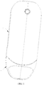
- an electronic cigarette includes an atomization device 1 and a power supply device 2 in some embodiments of the present disclosure.
- the power supply device 2 supplies electricity to the atomization device 1 such that the atomization device 1 can heat and atomize smoke oil for smoker.
- the atomization device 1 includes a liquid storage device 11 and an injection structure 12.
- a liquid storage cavity 13 is formed in the liquid storage device 11.
- the liquid storage device 11 includes a liquid injection opening 111 such that liquid can be injected into the liquid storage cavity 13 through the liquid injection opening 111.
- the injection structure 12 includes an injection tube 121 and a sealing member 122.
- the injection tube 121 runs through the liquid injection opening 111 and extends into the liquid storage cavity 13.
- a liquid inlet 1211 is formed in a sidewall of the injection tube 121.
- the sealing member 122 is arranged on one end of the injection tube 121 in the liquid storage cavity 13, the sealing member 122 is sealed from an inner wall of the liquid storage cavity 13 to separate the liquid inlet 1211 from the liquid storage cavity 13.
- the injection tube 121 When the injection tube 121 is pushed into the liquid storage cavity 13, the injection tube 121 moves into the liquid storage cavity 13, the sealing member 122 is separated from the liquid injection opening 111, and the liquid inlet 1211 moves into the liquid injection opening 111 to communicate with the liquid storage cavity 13, thus, it is convenient to inject smoke oil into the liquid storage cavity 13 through the liquid inlet 1211 of the injection tube 121.
- An exhaust gap A is defined between an outer surface of the injection tube 121 and an inner ring of the liquid injection opening 111.
- the injection mouth of the smoke oil bottle will suffer a counterforce and move into the smoke oil bottle to open the oil outlet in the injection mouth, thus, the smoke oil can flow out through the injection mouth.
- the smoke oil is injected to the atomization device 1 by flowing through the injection mouth, the injection tube 121, and the liquid inlet 1211 to the liquid storage cavity 13.
- the injection tube 121 when the injection tube 121 is not pushed, the injection tube 121 moves outwards to the original place to separate the liquid inlet 1211 from the liquid storage cavity 13, thus, the leakage of the smoke oil injected into the liquid storage cavity 13 can be avoided.
- the atomization device 1 also includes a sleeve 14 which communicates a space inside the liquid storage cavity 13 with a space outside the liquid storage cavity 13.
- the sleeve 14 includes a pipe 141 and an annular holder 142 arranged on an inner ring of on one end of the pipe 141.
- the liquid storage device 11 defines a mounting hole 112, and the sleeve 14 is inserted into the mounting hole 112.
- One end of the sleeve 14 where the annular holder 142 is located is in the liquid storage cavity 13, and an inner hole of the annular holder 142 forms the liquid injection opening 111.
- the sealing member 122 is on an inner surface of the annular holder 142 corresponding to the liquid storage cavity 13, and the sealing member 122 is sealed from the inner surface of the annular holder 142, thus, the leakage of the smoke oil injected into the liquid storage cavity 13 can be avoided.
- the location of the inside end of the sleeve 14 is not limited to this embodiment, it can be in the liquid storage cavity 13, or it can flush with the inner wall of the liquid storage cavity 13, or be embedded in an inner wall of the liquid storage device 11.
- the location of the annular holder 142 also can be adjusted correspondingly to allow the smoke oil to be injected into the liquid storage cavity 13 through the liquid injection opening 111.
- the sleeve 14 can also be integrated with the liquid storage device 11.
- an inner end of the injection tube 121 is enclosed, and the sealing member 122 is sleeved on one end of the injection tube 121.
- the sealing member 122 includes a mounting base 1221 and a sealing ring 1222; the mounting base 1221 is mounted on the inner end of the injection tube 121, and the sealing ring 1222 is sleeved on an outer ring of the mounting base 1221.
- the sealing ring 1222 can be made of flexible material.
- One end of the annular convex 1223 is arranged along a circumference of one side of the sealing ring 1222 adjacent to the liquid injection opening 111.
- the circular convex 1223 can be compressed and deformed easily, thus, the circular convex 1223 can help to seal the sealing ring 1222 from the annular holder 142 more effectively.
- the inner end of the injection tube 121 can be unclosed, and the sealing member 122 can be sealed from the inner end of the injection tube 121 after the installation of the sealing member 122.
- the injection structure 12 further includes a reset member 15.
- the reset member 15 abuts the injection tube 121 and the sleeve 14 respectively and provides elastic force to drive the sleeve 14 to move outwards such that the sealing member 122 is sealed from the annular holder 142.
- the reset member 15 is sleeved on the injection tube 121, and a positioning stage 1212 abutting against the reset member 15 is provided outside the injection tube 121.
- One end of the reset member 15 abuts the positioning stage 1212, and the other end of the reset member 15 abuts the annular holder 142.
- the injection structure 12 can further include a plurality of reset members 15 arranged around the circumference of the injection tube 121. Two ends of the reset member 15 are clamped to the positioning stage 1212 and the annular holder 142 to be positioned, thus, the reset member 15 can provide resetting elastic force.
- a sleeving tube 1213 is arranged on an outer end of the injection tube 121.
- a size of an inner hole of the sleeving tube 1213 is greater than that of an inner hole in the injection tube 121, thus, when the smoke oil is injected, it is convenient to insert the injection mouth firstly into the sleeving tube 1213, and it is convenient to push the injection tube 121 with the size difference between the injection tube 121 and the sleeving tube 1213.
- a trumpet-shaped guiding portion 1214 is formed between the sleeving tube 1213 and the injection tube 121, and one end of the guiding portion is bigger than the other end; the bigger end of the guiding portion 1214 is connected to the sleeving tube 1213, and the smaller end of the guiding portion 1214 is connected to the injection tube 121.
- the injection mouth of the smoke oil bottle can be close to the outer end of the injection tube 121 through the guiding portion 1214, and can push the injection tube 121 into the liquid storage cavity 13 with the guiding portion 1214, thus, the smoke oil can flow to the injection tube 121 through an inclined surface of the guiding portion 1214.
- a size of the bigger end of the guiding portion 1214 is larger than that of an inner ring of the sleeve 14.
- An exhaust cavity is formed between an inner surface of the sleeve 14 and the outer surface of the injection tube 121, and an outer end of the sleeve 14 defines an opening hole 143.
- the exhaust gap A, the exhaust cavity, and the opening hole 143 forms an exhaust channel communicating the liquid storage cavity 13 with the external environment; when the guiding portion 1214 abuts the outer end of the sleeve 14, the exhaust cavity can still be connected with the external environment by the opening hole 143 and exhaust normally.
Landscapes
- Engineering & Computer Science (AREA)
- General Engineering & Computer Science (AREA)
- Mechanical Engineering (AREA)
- Containers And Packaging Bodies Having A Special Means To Remove Contents (AREA)
- Catching Or Destruction (AREA)
- Special Spraying Apparatus (AREA)
- Disinfection, Sterilisation Or Deodorisation Of Air (AREA)
- Nozzles (AREA)
Applications Claiming Priority (1)
| Application Number | Priority Date | Filing Date | Title |
|---|---|---|---|
| CN201810341985.2A CN108354231B (zh) | 2018-04-17 | 2018-04-17 | 雾化装置和电子烟 |
Publications (2)
| Publication Number | Publication Date |
|---|---|
| EP3556233A1 true EP3556233A1 (fr) | 2019-10-23 |
| EP3556233B1 EP3556233B1 (fr) | 2021-08-18 |
Family
ID=63008350
Family Applications (1)
| Application Number | Title | Priority Date | Filing Date |
|---|---|---|---|
| EP18191921.8A Active EP3556233B1 (fr) | 2018-04-17 | 2018-08-31 | Dispositif d'atomisation et cigarette électronique en étant équipée |
Country Status (3)
| Country | Link |
|---|---|
| US (1) | US10893706B2 (fr) |
| EP (1) | EP3556233B1 (fr) |
| CN (1) | CN108354231B (fr) |
Cited By (2)
| Publication number | Priority date | Publication date | Assignee | Title |
|---|---|---|---|---|
| EP4118987A1 (fr) * | 2021-07-15 | 2023-01-18 | Shenzhen Eigate Technology Co., Ltd. | Atomiseur |
| WO2025067381A3 (fr) * | 2023-09-27 | 2025-05-01 | Shenzhen GT Grand Technology Co.,Ltd. | Appareil d'atomisation et dispositif d'atomisation |
Families Citing this family (24)
| Publication number | Priority date | Publication date | Assignee | Title |
|---|---|---|---|---|
| USD927772S1 (en) * | 2018-09-30 | 2021-08-10 | Shenzhen Smoore Technology Limited | Electronic cigarette |
| USD943146S1 (en) * | 2018-10-19 | 2022-02-08 | Shenzhen Smoore Technology Limited | Electronic atomizing device assembly |
| US11730201B2 (en) | 2019-04-15 | 2023-08-22 | Vaporous Technologies, Inc. | Personal vaporizer having a heating element with multiple surfaces |
| US11839238B2 (en) | 2019-05-15 | 2023-12-12 | Vaporous Technologies, Inc. | Personal vaporizer and method for filling same |
| USD943811S1 (en) * | 2019-07-19 | 2022-02-15 | Tuanfang Liu | Electronic cigarette |
| USD930235S1 (en) * | 2019-08-24 | 2021-09-07 | Tuanfang Liu | Electronic cigarette |
| WO2021056358A1 (fr) * | 2019-09-26 | 2021-04-01 | 深圳雾芯科技有限公司 | Dispositif de vaporisation |
| CN112568496B (zh) * | 2019-09-27 | 2024-09-27 | 深圳市吉迩科技有限公司 | 气道调节机构、气道调节方法及电子烟 |
| USD949462S1 (en) * | 2019-10-31 | 2022-04-19 | Shenzhen Verdewell Technology Limited | Electronic atomizing device |
| CN111406978A (zh) * | 2019-11-06 | 2020-07-14 | 深圳市艾维普思科技有限公司 | 电子烟的雾化器及电子烟 |
| US11330841B2 (en) | 2020-01-16 | 2022-05-17 | Vaporous Technologies, Inc. | Personal vaporizer for use with vial |
| WO2021158758A1 (fr) | 2020-02-04 | 2021-08-12 | Juul Labs, Inc. | Dispositif de distribution d'aérosol doté de récipient jetable |
| USD936279S1 (en) * | 2020-03-11 | 2021-11-16 | Joshua Israel | Vaporizing apparatus |
| CN111544713B (zh) * | 2020-04-28 | 2022-05-17 | 郝敏 | 一种封闭式雾化器 |
| CN113712443B (zh) * | 2020-05-26 | 2023-04-18 | 浙江天喜厨电股份有限公司 | 一种定量下液装置 |
| CN112189897B (zh) * | 2020-10-23 | 2025-07-18 | 深圳麦克韦尔科技有限公司 | 一种雾化器及其电子雾化装置 |
| CN113303513A (zh) * | 2021-06-20 | 2021-08-27 | 张鹏程 | 一种电子烟的雾化装置 |
| CN113455717A (zh) * | 2021-07-15 | 2021-10-01 | 深圳易佳特科技有限公司 | 一种注油方便的雾化器 |
| US20240049799A1 (en) * | 2021-10-20 | 2024-02-15 | Shenzhen Zun Yi Pin Technology Co., Ltd. | Liquid injection device and method |
| WO2023122948A1 (fr) * | 2021-12-28 | 2023-07-06 | 深圳麦克韦尔科技有限公司 | Dispositif d'atomisation électronique et atomiseur |
| CN218219157U (zh) * | 2022-01-21 | 2023-01-06 | 深圳易佳特科技有限公司 | 雾化器及电子烟 |
| US11533950B1 (en) | 2022-02-09 | 2022-12-27 | Clear IP Corporation | Atomizer cartridge with integrally formed internal fluid reservoir and mouthpiece portion |
| CN115316715A (zh) * | 2022-08-04 | 2022-11-11 | 深圳市新埃法科技有限公司 | 一种带储油棉的一次性电子烟防漏油结构 |
| CN220236041U (zh) * | 2023-04-12 | 2023-12-26 | 深圳麦克韦尔科技有限公司 | 雾化器及电子雾化装置 |
Citations (3)
| Publication number | Priority date | Publication date | Assignee | Title |
|---|---|---|---|---|
| US5249611A (en) * | 1987-03-16 | 1993-10-05 | Vemco, Inc. | Pour spout |
| CN105192896A (zh) * | 2015-10-28 | 2015-12-30 | 深圳麦克韦尔股份有限公司 | 烟油瓶及电子烟 |
| WO2018046530A1 (fr) * | 2016-09-06 | 2018-03-15 | Fontem Holdings 1 B.V. | Dispositif électronique pour fumer avec réservoir de liquide remplissable |
Family Cites Families (3)
| Publication number | Priority date | Publication date | Assignee | Title |
|---|---|---|---|---|
| CN205358217U (zh) * | 2015-10-28 | 2016-07-06 | 深圳麦克韦尔股份有限公司 | 烟油瓶及电子烟 |
| CN206866632U (zh) * | 2017-05-25 | 2018-01-12 | 深圳麦克韦尔股份有限公司 | 雾化装置及电子烟 |
| CN208338874U (zh) * | 2018-04-17 | 2019-01-08 | 深圳麦克韦尔股份有限公司 | 雾化装置和电子烟 |
-
2018
- 2018-04-17 CN CN201810341985.2A patent/CN108354231B/zh active Active
- 2018-08-31 EP EP18191921.8A patent/EP3556233B1/fr active Active
- 2018-09-03 US US16/120,389 patent/US10893706B2/en active Active
Patent Citations (4)
| Publication number | Priority date | Publication date | Assignee | Title |
|---|---|---|---|---|
| US5249611A (en) * | 1987-03-16 | 1993-10-05 | Vemco, Inc. | Pour spout |
| CN105192896A (zh) * | 2015-10-28 | 2015-12-30 | 深圳麦克韦尔股份有限公司 | 烟油瓶及电子烟 |
| EP3348155A1 (fr) * | 2015-10-28 | 2018-07-18 | Shenzhen Smoore Technology Limited | Flacon de liquide à vapoter et cigarette électronique |
| WO2018046530A1 (fr) * | 2016-09-06 | 2018-03-15 | Fontem Holdings 1 B.V. | Dispositif électronique pour fumer avec réservoir de liquide remplissable |
Cited By (2)
| Publication number | Priority date | Publication date | Assignee | Title |
|---|---|---|---|---|
| EP4118987A1 (fr) * | 2021-07-15 | 2023-01-18 | Shenzhen Eigate Technology Co., Ltd. | Atomiseur |
| WO2025067381A3 (fr) * | 2023-09-27 | 2025-05-01 | Shenzhen GT Grand Technology Co.,Ltd. | Appareil d'atomisation et dispositif d'atomisation |
Also Published As
| Publication number | Publication date |
|---|---|
| US10893706B2 (en) | 2021-01-19 |
| EP3556233B1 (fr) | 2021-08-18 |
| CN108354231A (zh) | 2018-08-03 |
| US20190313693A1 (en) | 2019-10-17 |
| CN108354231B (zh) | 2023-10-27 |
Similar Documents
| Publication | Publication Date | Title |
|---|---|---|
| US10893706B2 (en) | Atomization device and electronic cigarette with the same | |
| US11882881B2 (en) | Atomization device and electronic cigarette with the same | |
| CN108208935B (zh) | 雾化器及其电子烟 | |
| EP3135140B1 (fr) | Alimentation en liquide, dispositif d'atomisation et cigarette électronique comportant ceux-ci | |
| CN111109660B (zh) | 电源组件、雾化器及电子雾化装置 | |
| CN107205475B (zh) | 一种电子烟及其防烟油泄露的方法 | |
| CN211048395U (zh) | 雾化器及电子烟 | |
| US9968135B2 (en) | Electronic cigarette with oil observation strip | |
| CN203467677U (zh) | 电子烟透明雾化器 | |
| CN111329109B (zh) | 一种防漏油和防重复注油的气溶胶雾化器及包含其的电子烟 | |
| EP3289897A1 (fr) | Dispositif d'atomisation et cigarette électronique le comportant | |
| WO2016202303A1 (fr) | Atomiseur et appareil de génération d'aérosol | |
| WO2018214122A1 (fr) | Dispositif d'atomisation et cigarette électronique | |
| WO2018133267A1 (fr) | Dispositif de stockage de liquide, atomiseur et cigarette électronique | |
| CN217743169U (zh) | 具有防漏液结构的雾化器及雾化装置 | |
| CN105192892A (zh) | 敞口注液电子烟雾化器 | |
| CN111109667B (zh) | 一种防漏油的气溶胶雾化器及包含其的电子烟 | |
| CN209073562U (zh) | 一种侧面注油的免拆卸旋转雾化器 | |
| CN215775558U (zh) | 电子雾化装置及其雾化器 | |
| CN211910514U (zh) | 雾化器及电子烟 | |
| CN205143487U (zh) | 顶部加油雾化器 | |
| CN216165151U (zh) | 一种油芯分离防漏油的雾化器 | |
| CN105982359A (zh) | 顶部注液防盗电子烟装置 | |
| CN208113975U (zh) | 雾化装置及电子烟 | |
| CN217184845U (zh) | 雾化弹及雾化设备 |
Legal Events
| Date | Code | Title | Description |
|---|---|---|---|
| PUAI | Public reference made under article 153(3) epc to a published international application that has entered the european phase |
Free format text: ORIGINAL CODE: 0009012 |
|
| STAA | Information on the status of an ep patent application or granted ep patent |
Free format text: STATUS: REQUEST FOR EXAMINATION WAS MADE |
|
| 17P | Request for examination filed |
Effective date: 20190904 |
|
| AK | Designated contracting states |
Kind code of ref document: A1 Designated state(s): AL AT BE BG CH CY CZ DE DK EE ES FI FR GB GR HR HU IE IS IT LI LT LU LV MC MK MT NL NO PL PT RO RS SE SI SK SM TR |
|
| AX | Request for extension of the european patent |
Extension state: BA ME |
|
| REG | Reference to a national code |
Ref country code: DE Ref legal event code: R079 Ref document number: 602018021926 Country of ref document: DE Free format text: PREVIOUS MAIN CLASS: A24F0047000000 Ipc: A24F0040485000 |
|
| GRAP | Despatch of communication of intention to grant a patent |
Free format text: ORIGINAL CODE: EPIDOSNIGR1 |
|
| STAA | Information on the status of an ep patent application or granted ep patent |
Free format text: STATUS: GRANT OF PATENT IS INTENDED |
|
| RIC1 | Information provided on ipc code assigned before grant |
Ipc: A24F 15/015 20200101ALN20210413BHEP Ipc: A24F 40/10 20200101ALN20210413BHEP Ipc: F16K 3/26 20060101ALI20210413BHEP Ipc: A24F 40/485 20200101AFI20210413BHEP |
|
| INTG | Intention to grant announced |
Effective date: 20210512 |
|
| GRAS | Grant fee paid |
Free format text: ORIGINAL CODE: EPIDOSNIGR3 |
|
| GRAA | (expected) grant |
Free format text: ORIGINAL CODE: 0009210 |
|
| STAA | Information on the status of an ep patent application or granted ep patent |
Free format text: STATUS: THE PATENT HAS BEEN GRANTED |
|
| AK | Designated contracting states |
Kind code of ref document: B1 Designated state(s): AL AT BE BG CH CY CZ DE DK EE ES FI FR GB GR HR HU IE IS IT LI LT LU LV MC MK MT NL NO PL PT RO RS SE SI SK SM TR |
|
| REG | Reference to a national code |
Ref country code: GB Ref legal event code: FG4D |
|
| REG | Reference to a national code |
Ref country code: CH Ref legal event code: EP |
|
| REG | Reference to a national code |
Ref country code: DE Ref legal event code: R096 Ref document number: 602018021926 Country of ref document: DE |
|
| REG | Reference to a national code |
Ref country code: IE Ref legal event code: FG4D Ref country code: AT Ref legal event code: REF Ref document number: 1420814 Country of ref document: AT Kind code of ref document: T Effective date: 20210915 |
|
| REG | Reference to a national code |
Ref country code: LT Ref legal event code: MG9D |
|
| REG | Reference to a national code |
Ref country code: NL Ref legal event code: MP Effective date: 20210818 |
|
| REG | Reference to a national code |
Ref country code: AT Ref legal event code: MK05 Ref document number: 1420814 Country of ref document: AT Kind code of ref document: T Effective date: 20210818 |
|
| PG25 | Lapsed in a contracting state [announced via postgrant information from national office to epo] |
Ref country code: ES Free format text: LAPSE BECAUSE OF FAILURE TO SUBMIT A TRANSLATION OF THE DESCRIPTION OR TO PAY THE FEE WITHIN THE PRESCRIBED TIME-LIMIT Effective date: 20210818 Ref country code: FI Free format text: LAPSE BECAUSE OF FAILURE TO SUBMIT A TRANSLATION OF THE DESCRIPTION OR TO PAY THE FEE WITHIN THE PRESCRIBED TIME-LIMIT Effective date: 20210818 Ref country code: HR Free format text: LAPSE BECAUSE OF FAILURE TO SUBMIT A TRANSLATION OF THE DESCRIPTION OR TO PAY THE FEE WITHIN THE PRESCRIBED TIME-LIMIT Effective date: 20210818 Ref country code: SE Free format text: LAPSE BECAUSE OF FAILURE TO SUBMIT A TRANSLATION OF THE DESCRIPTION OR TO PAY THE FEE WITHIN THE PRESCRIBED TIME-LIMIT Effective date: 20210818 Ref country code: RS Free format text: LAPSE BECAUSE OF FAILURE TO SUBMIT A TRANSLATION OF THE DESCRIPTION OR TO PAY THE FEE WITHIN THE PRESCRIBED TIME-LIMIT Effective date: 20210818 Ref country code: LT Free format text: LAPSE BECAUSE OF FAILURE TO SUBMIT A TRANSLATION OF THE DESCRIPTION OR TO PAY THE FEE WITHIN THE PRESCRIBED TIME-LIMIT Effective date: 20210818 Ref country code: AT Free format text: LAPSE BECAUSE OF FAILURE TO SUBMIT A TRANSLATION OF THE DESCRIPTION OR TO PAY THE FEE WITHIN THE PRESCRIBED TIME-LIMIT Effective date: 20210818 Ref country code: BG Free format text: LAPSE BECAUSE OF FAILURE TO SUBMIT A TRANSLATION OF THE DESCRIPTION OR TO PAY THE FEE WITHIN THE PRESCRIBED TIME-LIMIT Effective date: 20211118 Ref country code: PT Free format text: LAPSE BECAUSE OF FAILURE TO SUBMIT A TRANSLATION OF THE DESCRIPTION OR TO PAY THE FEE WITHIN THE PRESCRIBED TIME-LIMIT Effective date: 20211220 Ref country code: NO Free format text: LAPSE BECAUSE OF FAILURE TO SUBMIT A TRANSLATION OF THE DESCRIPTION OR TO PAY THE FEE WITHIN THE PRESCRIBED TIME-LIMIT Effective date: 20211118 |
|
| PG25 | Lapsed in a contracting state [announced via postgrant information from national office to epo] |
Ref country code: PL Free format text: LAPSE BECAUSE OF FAILURE TO SUBMIT A TRANSLATION OF THE DESCRIPTION OR TO PAY THE FEE WITHIN THE PRESCRIBED TIME-LIMIT Effective date: 20210818 Ref country code: LV Free format text: LAPSE BECAUSE OF FAILURE TO SUBMIT A TRANSLATION OF THE DESCRIPTION OR TO PAY THE FEE WITHIN THE PRESCRIBED TIME-LIMIT Effective date: 20210818 Ref country code: GR Free format text: LAPSE BECAUSE OF FAILURE TO SUBMIT A TRANSLATION OF THE DESCRIPTION OR TO PAY THE FEE WITHIN THE PRESCRIBED TIME-LIMIT Effective date: 20211119 |
|
| REG | Reference to a national code |
Ref country code: CH Ref legal event code: PL |
|
| PG25 | Lapsed in a contracting state [announced via postgrant information from national office to epo] |
Ref country code: NL Free format text: LAPSE BECAUSE OF FAILURE TO SUBMIT A TRANSLATION OF THE DESCRIPTION OR TO PAY THE FEE WITHIN THE PRESCRIBED TIME-LIMIT Effective date: 20210818 |
|
| REG | Reference to a national code |
Ref country code: BE Ref legal event code: MM Effective date: 20210831 |
|
| PG25 | Lapsed in a contracting state [announced via postgrant information from national office to epo] |
Ref country code: LI Free format text: LAPSE BECAUSE OF NON-PAYMENT OF DUE FEES Effective date: 20210831 Ref country code: DK Free format text: LAPSE BECAUSE OF FAILURE TO SUBMIT A TRANSLATION OF THE DESCRIPTION OR TO PAY THE FEE WITHIN THE PRESCRIBED TIME-LIMIT Effective date: 20210818 Ref country code: CH Free format text: LAPSE BECAUSE OF NON-PAYMENT OF DUE FEES Effective date: 20210831 |
|
| REG | Reference to a national code |
Ref country code: DE Ref legal event code: R097 Ref document number: 602018021926 Country of ref document: DE |
|
| PG25 | Lapsed in a contracting state [announced via postgrant information from national office to epo] |
Ref country code: SM Free format text: LAPSE BECAUSE OF FAILURE TO SUBMIT A TRANSLATION OF THE DESCRIPTION OR TO PAY THE FEE WITHIN THE PRESCRIBED TIME-LIMIT Effective date: 20210818 Ref country code: SK Free format text: LAPSE BECAUSE OF FAILURE TO SUBMIT A TRANSLATION OF THE DESCRIPTION OR TO PAY THE FEE WITHIN THE PRESCRIBED TIME-LIMIT Effective date: 20210818 Ref country code: RO Free format text: LAPSE BECAUSE OF FAILURE TO SUBMIT A TRANSLATION OF THE DESCRIPTION OR TO PAY THE FEE WITHIN THE PRESCRIBED TIME-LIMIT Effective date: 20210818 Ref country code: MC Free format text: LAPSE BECAUSE OF FAILURE TO SUBMIT A TRANSLATION OF THE DESCRIPTION OR TO PAY THE FEE WITHIN THE PRESCRIBED TIME-LIMIT Effective date: 20210818 Ref country code: LU Free format text: LAPSE BECAUSE OF NON-PAYMENT OF DUE FEES Effective date: 20210831 Ref country code: EE Free format text: LAPSE BECAUSE OF FAILURE TO SUBMIT A TRANSLATION OF THE DESCRIPTION OR TO PAY THE FEE WITHIN THE PRESCRIBED TIME-LIMIT Effective date: 20210818 Ref country code: CZ Free format text: LAPSE BECAUSE OF FAILURE TO SUBMIT A TRANSLATION OF THE DESCRIPTION OR TO PAY THE FEE WITHIN THE PRESCRIBED TIME-LIMIT Effective date: 20210818 Ref country code: AL Free format text: LAPSE BECAUSE OF FAILURE TO SUBMIT A TRANSLATION OF THE DESCRIPTION OR TO PAY THE FEE WITHIN THE PRESCRIBED TIME-LIMIT Effective date: 20210818 |
|
| PLBE | No opposition filed within time limit |
Free format text: ORIGINAL CODE: 0009261 |
|
| STAA | Information on the status of an ep patent application or granted ep patent |
Free format text: STATUS: NO OPPOSITION FILED WITHIN TIME LIMIT |
|
| 26N | No opposition filed |
Effective date: 20220519 |
|
| PG25 | Lapsed in a contracting state [announced via postgrant information from national office to epo] |
Ref country code: IT Free format text: LAPSE BECAUSE OF FAILURE TO SUBMIT A TRANSLATION OF THE DESCRIPTION OR TO PAY THE FEE WITHIN THE PRESCRIBED TIME-LIMIT Effective date: 20210818 Ref country code: IE Free format text: LAPSE BECAUSE OF NON-PAYMENT OF DUE FEES Effective date: 20210831 Ref country code: BE Free format text: LAPSE BECAUSE OF NON-PAYMENT OF DUE FEES Effective date: 20210831 |
|
| PG25 | Lapsed in a contracting state [announced via postgrant information from national office to epo] |
Ref country code: SI Free format text: LAPSE BECAUSE OF FAILURE TO SUBMIT A TRANSLATION OF THE DESCRIPTION OR TO PAY THE FEE WITHIN THE PRESCRIBED TIME-LIMIT Effective date: 20210818 |
|
| P01 | Opt-out of the competence of the unified patent court (upc) registered |
Effective date: 20230428 |
|
| PG25 | Lapsed in a contracting state [announced via postgrant information from national office to epo] |
Ref country code: CY Free format text: LAPSE BECAUSE OF FAILURE TO SUBMIT A TRANSLATION OF THE DESCRIPTION OR TO PAY THE FEE WITHIN THE PRESCRIBED TIME-LIMIT Effective date: 20210818 |
|
| PG25 | Lapsed in a contracting state [announced via postgrant information from national office to epo] |
Ref country code: HU Free format text: LAPSE BECAUSE OF FAILURE TO SUBMIT A TRANSLATION OF THE DESCRIPTION OR TO PAY THE FEE WITHIN THE PRESCRIBED TIME-LIMIT; INVALID AB INITIO Effective date: 20180831 |
|
| PG25 | Lapsed in a contracting state [announced via postgrant information from national office to epo] |
Ref country code: MK Free format text: LAPSE BECAUSE OF FAILURE TO SUBMIT A TRANSLATION OF THE DESCRIPTION OR TO PAY THE FEE WITHIN THE PRESCRIBED TIME-LIMIT Effective date: 20210818 |
|
| PG25 | Lapsed in a contracting state [announced via postgrant information from national office to epo] |
Ref country code: MT Free format text: LAPSE BECAUSE OF FAILURE TO SUBMIT A TRANSLATION OF THE DESCRIPTION OR TO PAY THE FEE WITHIN THE PRESCRIBED TIME-LIMIT Effective date: 20210818 |
|
| PGFP | Annual fee paid to national office [announced via postgrant information from national office to epo] |
Ref country code: DE Payment date: 20250812 Year of fee payment: 8 |
|
| PGFP | Annual fee paid to national office [announced via postgrant information from national office to epo] |
Ref country code: GB Payment date: 20250826 Year of fee payment: 8 |
|
| PGFP | Annual fee paid to national office [announced via postgrant information from national office to epo] |
Ref country code: FR Payment date: 20250828 Year of fee payment: 8 |
|
| PG25 | Lapsed in a contracting state [announced via postgrant information from national office to epo] |
Ref country code: TR Free format text: LAPSE BECAUSE OF FAILURE TO SUBMIT A TRANSLATION OF THE DESCRIPTION OR TO PAY THE FEE WITHIN THE PRESCRIBED TIME-LIMIT Effective date: 20210818 |