EP3556442B1 - Ensemble de retour de balle de bowling - Google Patents
Ensemble de retour de balle de bowling Download PDFInfo
- Publication number
- EP3556442B1 EP3556442B1 EP19170543.3A EP19170543A EP3556442B1 EP 3556442 B1 EP3556442 B1 EP 3556442B1 EP 19170543 A EP19170543 A EP 19170543A EP 3556442 B1 EP3556442 B1 EP 3556442B1
- Authority
- EP
- European Patent Office
- Prior art keywords
- customizable
- bowling
- housing
- housing body
- modular
- Prior art date
- Legal status (The legal status is an assumption and is not a legal conclusion. Google has not performed a legal analysis and makes no representation as to the accuracy of the status listed.)
- Active
Links
Images






Classifications
-
- A—HUMAN NECESSITIES
- A63—SPORTS; GAMES; AMUSEMENTS
- A63D—BOWLING GAMES, e.g. SKITTLES, BOCCE OR BOWLS; INSTALLATIONS THEREFOR; BAGATELLE OR SIMILAR GAMES; BILLIARDS
- A63D5/00—Accessories for bowling-alleys or table alleys
- A63D5/02—Apparatus for trapping or lifting the balls; Separate devices for returning the balls
-
- A—HUMAN NECESSITIES
- A63—SPORTS; GAMES; AMUSEMENTS
- A63D—BOWLING GAMES, e.g. SKITTLES, BOCCE OR BOWLS; INSTALLATIONS THEREFOR; BAGATELLE OR SIMILAR GAMES; BILLIARDS
- A63D5/00—Accessories for bowling-alleys or table alleys
- A63D5/02—Apparatus for trapping or lifting the balls; Separate devices for returning the balls
- A63D5/023—Separate devices for returning the balls
Definitions
- the present disclosure relates to bowling, and in particular, mechanisms, systems, or assemblies for returning bowling balls to bowlers.
- Bowling ball returns are generally among the most highly visible parts of a bowling center's interior design. Existing bowling ball returns, however, traditionally have been offered only in a limited number of configurations, colors, designs, etc. Manufacturers typically standardize the manufactured design and color options for ball returns to minimize manufacturing inconsistencies, setup and inventory costs, etc. In addition, the housing and/or other components of typical bowling ball returns often are formed by injection molding techniques, with the manufacturer's signature color generally injected during the molding process or by painting the formed housing/components before assembly.
- the manufacturer usually must paint the housing or other components of the bowling ball return and/or pass any further costs of such customization to the customer.
- Such a process also generally does not allow for specific images, textures, finishes, etc. to be customizably incorporated within the housing or other components of the bowling ball return, particularly after installation of the bowling ball return.
- US 2014/087891 A1 teaches that an adhesive sheet material can be placed over a ball return to correspond to mural images on a bowling lane.
- the present disclosure provides a customizable bowling ball return assembly.
- the customizable bowling ball return assembly can include a housing or housing portion that is positioned adjacent to a retrieval area that receives bowling balls for retrieval by bowlers at a lane or lanes.
- the housing can include a passage or discharge defined therein that is sized, dimensioned, or configured to allow for passage of the one or more bowling balls to the retrieval area.
- the bowling ball return assembly further can comprise one or more customizable, modular, or interchangeable portions of a selected size, dimension, shape, or configuration that are configured to be selectively coupled to the housing.
- the one or more customizable, modular, or interchangeable portions can include a surface or face with one or more selected colors, images, depictions, graphics, themes, finishes, textures, or combinations thereof provided on the surface or face.
- the bowling ball return assembly can include an automated return mechanism that is operable to direct bowling balls to a retrieval area.
- the housing can at least partially enclose or surround the return mechanism.
- the return mechanism can include a plurality of belts, rotating wheels, or other drive mechanisms that move and/or guide the returned bowling balls along at least one set of guide rails towards and through a passage/throat in the housing for discharge of the balls onto the one or more supports and/or rails of the retrieval area.
- the bowling ball return assembly can include a surface return assembly
- the housing can include a passage with a track or path defined therethrough that allows for passage of bowling balls from a track or guide area provided along the bowling lanes through the housing and to the retrieval area.
- the retrieval area can include an elongated body configured to receive and support a plurality of bowling balls, and in some embodiments, can have one or more supports and/or rails that at least partially support the returned bowling balls for retrieval by a bowler(s).
- the elongated body of the retrieval area can have a track/guide surface that receives/supports the bowling balls.
- the one or more customizable, modular, and/or interchangeable sections or portions that can have various sizes, dimensions, shapes, configurations, etc. and can be selectively configurable and selectively coupled to the housing of the bowling ball return assembly.
- the customizable sections/portions also can include one or more colors, images, depictions, graphics, themes, finishes, textures, etc., or combinations thereof.
- each of the sections or portions can include one or more selected colors, graphics, textures, finishes, etc. that can be selected by a customer, for example, to correspond to a theme or otherwise match the interior design of the customer's bowling center.
- the customizable sections/portions further can be formed from a high-pressure laminate material.
- the customizable sections/portions can include a substrate layer, e.g., formed from a plywood, a fiberboard material, etc. or other composite materials that is formed into the customizable section shape, and a design or décor layer, including a laminate sheet material, plastic material, or paper material received/applied over the substrate layer.
- the design layer can include one or more colors, graphics, pictures, images, textures, finishes, etc., e.g., which can be selected by a customer/user to customize the bowling ball return assembly.
- the bowling ball return assembly further can include one or more connecting mechanisms, such as fasteners, adhesives, snap-fitted connections, etc., that are configured to releasably couple the customizable sections/portions together and/or to at least part of the housing.
- the sections/portions of the bowling ball return assembly thus can be made to be interchangeable to enable further customization as needed or desired.
- one or more adhesives such as double-sided adhesive tape or other suitable adhesives, can be applied to the customizable sections/portions and/or the housing of the bowling ball return assembly to couple the customizable sections/portions together and/or to the housing.
- the bowling ball return assembly further can include one or more connecting members or portions that releasably couple to the customizable sections/portions together and/or to at least a portion of the housing.
- the connecting members can have an elongated body with one or more grooves or slots defined therein that receive at least a portion, e.g., an end portion, of the customizable sections/portions to secure the customizable portions thereto, e.g., in slidable frictional engagement.
- one or more fasteners can be used to secure at least a portion of the customizable sections/portions to the connecting members and/or to the housing.
- the customizable bowling ball return assembly further can include one or more light sources, LEDs, etc., arranged therealong.
- the one or more light sources can be positioned along the connecting members to illuminate portions of the bowling ball return assembly or an area adjacent thereto.
- the light sources can be positioned along any suitable portion of the bowling ball return assembly, however, without departing from the scope of the present disclosure.
- the housing and/or one or more of the plurality of customizable, interchangeable sections/portions also can have one or more translucent portions or areas. These translucent portions or areas can be used to provide additional visual effects. For example, such translucent portions or areas further can be illuminated by one or more light sources.
- Figs. 1A-10 generally illustrate various example embodiments of a customizable bowling ball return assembly 10, 200 according to the principles of the present disclosure. It should be understood that while the customizable bowling ball return assembly 10, 200 has been illustrated in the various figures with various colors, themes or other decorative aspects, and various configurations with customizable sections 12, 212 thereof being illustrated with varying or different shapes, configurations, sizes, etc., such decorative depictions and sizes, configurations, designs, etc. are shown merely for illustrative purposes and should not be viewed as limiting the present customizable bowling ball return assembly.
- various sections 12, 212 of the customizable bowling ball return assembly 10, 200 can be formed and releasably connected together to form a variety of different, customized designs to meet user/customer specifications or preferences for the bowling ball return assembly, without departing from the spirit and scope of the present disclosure.
- Figs. 1A - 1E show perspective views of a customizable bowling ball return assembly 10 according to principles of the present disclosure.
- the customizable bowling ball return assembly 10 generally can include a housing or housing portion 14 having a throat or discharge 16; and a bowling ball retrieval area 18 including at least one rail 20 and/or other suitable supports 48 for supporting a series of bowling balls 22 within the defined retrieval area 18.
- the bowling ball return assembly 10 can include a return mechanism 24 for returning bowling balls to the retrieval area 18.
- the bowling ball return assembly 10 also can include at least one control interface 26 operable to allow for control of operations at one or more bowling lanes of the bowling center 50 also can be provided, as indicated in Fig. 1C .
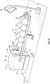
- Fig. 2 shows an exemplary ball return mechanism 24 according to one example of the present disclosure.
- the return mechanism 24 can include any suitable device that is operable to return bowling balls 22 to the retrieval area 18 for retrieval by a bowler without departing from the scope of the present disclosure.
- the return mechanism 24 can be recessed into the bowling alley floor 28, with a base plate 30 supporting the bottom portion 32 of the return mechanism 24 below the floor 28 of the bowling center, and a lane plate 34 generally supporting a middle portion 36 of the return mechanism 24 on or above the alley floor 28.
- Bowling balls 22 generally will enter at the bottom 32 of the return mechanism 24, which will lift the bowling balls 22 towards and through the throat/discharge 16 of the housing 14 whereupon the bowling balls 22 can be received and collected along the retrieval area 18.
- the return mechanism 24 also can include a first set of guide rails 38 and an oppositely-oriented second set of guide rails 40 that guide the bowling ball 22 along an upward path 42 through the return mechanism 24.
- the return mechanism 24 further can include rotating wheels 44 or other driving mechanism(s) that can engage and move the bowling balls 22 along the path 42 defined by the guide rails 38/40.
- the wheels 44 can be driven by a drive motor 46, though other suitable drive mechanisms or actuators can be used, without departing from the scope of the present disclosure.
- the operation of the drive motor or other components of the return mechanism may be in continuous operation or non-continuous operation, i.e ., the motor or other components of the return mechanism are only operated when a bowling ball enters the bottom of the return mechanism and is moved therethrough, such that once the bowling ball has moved through and released from the return mechanism, the drive motor or other components of the return mechanism can be shut off.
- Example return mechanisms are shown and described in U.S. Patent Application No. 14/684,736 .
- the bowling ball return assembly of the present disclosure further can include a surface ball return assembly 200 as illustrated in the embodiments shown in Figs. 4A-5B (discussed below).
- the bowling balls 22 exit the return mechanism 24 through the throat 16 in the housing 14.
- the throat 16 generally will be sized to be larger than a standard bowling ball; however, the size of the throat 16 may be varied, including being significantly larger than the size of a standard bowling ball, which may be differently defined by private bowling organizations of leagues. For example, the Professional Bowlers Association in United States indicates that the standard size of a bowling ball has a circumference of no more than 27 inches and a weight in the range of 10 to 16 pounds. It will be recognized, however, that other organizations, leagues, etc. may establish other standard bowling ball sizes.
- the throat 16 further can be dimensioned, sized, or otherwise configured to accommodate duckpin, fire-pin, candlepin, etc., or other suitable bowling balls, without departing from the scope of the present disclosure.
- Figs. 1A-1E additionally show that the retrieval area 18 generally includes a rail 20 and at least one center support 48 that at least partially defines a track or racking area 50 that can receive and retain a series of bowling balls 22 after they have been returned by the return mechanism 24 for retrieval by a bowler.
- the rail 20 can define a substantially arcuate, U-shaped, or otherwise shaped member having end portions 20A and 20B that are coupled to the housing 14 and/or customizable sections/portions 12. While the rail 20 is shown as generally U-shaped, the rail 20 can include any suitable shape and/or configuration, without departing from the scope of the present disclosure.
- At least a portion of the rail 20 further can be connected to the center support 48 of the retrieval area, on which the bowling balls are received.
- at least one post, column or other suitable support 52 can be provided to at least partially support the center support 48, and the rail 20 coupled thereto above the alley floor 28, as indicated in Figs. 1A-1D .
- the post 52 can be coupled to a lower surface 48A of the center support 48, and to the floor 28 of the bowling center, e.g., by one or more fasteners or other suitable fixing or attachment mechanisms.
- Figs. 3A, 3B show example housings 14 for the customizable bowling ball return assembly 10.
- the housing 14 can have a body 60 that can be engaged with the plate 34 and/or the bowling center floor 28.
- the housing body 60 can have a front 62, rear 64, side 66 and 68, top 70, and/or a bottom 72 parts that together at least partially surround and protect the internal components of the return mechanism 24 from damage, or from being accessed by bowlers.
- the configuration of the housing body 60 also can be structured to restrict access internally thereto, to try to minimize physical injuries to bowlers, for example, bowlers that intentionally or unintentionally reach into the moving components of the return mechanism.
- the housing 14 can include front and rear portions or plates with at least one of the customizable portion/sections 12 provided therebetween.
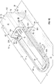
- Figs. 4A and 4B show a customizable bowling ball assembly 200 according to alternative/additional principles of the present disclosure.
- the bowling ball return assembly 200 is constructed/configured as a surface ball return assembly.
- the bowling ball assembly 200 generally includes a housing 214 with a body 260 that rests on or otherwise engages the bowling center floor 28.
- the housing 214 further has a passage or opening 202 defined therethrough that allows for the passage of bowling balls 22 to a retrieval area 218.
- the bowling ball return assembly 200 has a track or path 204 that extends/guides bowling balls 22 through /along the housing 214 (e.g., through the passage/opening 202) and to the retrieval area 218.
- the track or path 204 can have a first portion/area 206 having a ramped or sloped shape/construction/configuration to guide the bowling balls up towards and through the housing 212, and a second portion/area 208 with a generally straight shape/construction/configuration that guides the bowling balls 22 through the housing 214 (e.g., through passage 202) and then the retrieval area 218.
- the track/path 204 can have one or more guide surfaces 204A with a curved or arcuate shape that is generally complementary to the outer surface of the bowling balls 22 and further is configured to engage/contact the bowling balls 22 as they move therealong.
- the track/path 204 further can include guides, rails or other protruding/extending portions 204B provided therealong.
- the guides 204B are configured to contact/engage the bowling balls 22 as they move along the track 204, e.g., to substantially reduce, prevent, or inhibit the bowling balls 22 from being displaced/dislodged from, such as by bouncing out of, etc. the track as they move therealong.
- the track 204 can be in communication with a similarly constructed track 250 that extends/travels along the bowling lane(s).
- the track 250 can have a slope or grade variant that causes the balls to move therealong, e.g., by force/acceleration of gravity, towards the bowling ball assembly 200.
- bowling balls 22 that are rolled down the lane can be loaded onto the track 250 by one or more lifting mechanisms (e.g., including a lift(s), rotating wheel(s), etc.) so that the balls then will travel down the track 250 towards the bowling ball return assembly 200 on to track 204 to be directed through the housing 214 and onto the retrieval area 218.
- the bowling ball return assembly 200, track 204, track 250, etc. can generally be sized, dimensioned, or configured for return of bowling balls of any size, type, etc., such as ten-pin balls, duckpin balls, five-pin balls, candlepin balls, etc.
- Fig. 4A further shows that the housing 214 can have an upper portion 252 that covers/extends over at least a portion of the track 204 (e.g., at least part of the second portion/area 208).
- the upper portion 252 can at least partially define an opening/discharge 254 that allows for passage of the bowling balls 22 onto the retrieval area 218.
- the upper portion 252 can be omitted, however, as shown in Fig. 4A , and the housing 214 can have an opening or aperture 256 or otherwise can be open along an upper or top portion thereof.
- the second portion 208 of the track 204 and bowling balls 22 moving therealong are generally visible to the bowlers/customers at the lane.
- the retrieval area 218 can have an elongated body, rail, support, etc. 258 with a track 262 defined therealong to support/hold the bowling balls 22, e.g., until they are retrieved by bowlers at the lane.
- the track 262 is in communication with track 204 for receiving the bowling balls 22 therefrom.
- the elongated body 258 can have a stop portion 264 at an end 250A thereof that is configured to engage/stop the bowling balls along the track 262 for holding in the retrieval area 218.
- the retrieval area 218 further can include a post, support, etc. 266 that supports the elongated body 258 on the floor 28.
- Figs. 1A-1E , 3A-3B and 4A-4B further show that the housing 14, 214 can include one or more customizable, interchangeable sections or portions 12, 212 that can be selectively coupled to and/or can form or define the various parts of the housing body 60, 260 (e.g., between rear and forward portions of the housing body 60).
- the customizable, interchangeable sections or portions 12, 212 generally will include at least one surface or face 80, 280 with one or more colors, designs, graphics, textures, etc., for example, that can be selected by a user.
- Table 1 provides example colors or designs for the at least one surface or face 80, 280.
- the customizable, interchangeable sections or portions 12, 212 further can be readily attached to and detached from the housing body 60, 260 to allow the housing body 60, 260 to be customized, for example, to match one or more themes, designs, etc. of the bowling center.
- TABLE 1 Color Name SKU Evo Shell 537906 Shantung Amber 537540 Weathered Shingle Grey 537923 Horizon Mist 537916 Baha Oasis 537981 Cerused Graphite 537798 Warehouse Painted Plank 538022 Warehouse Worn Plank 538119 Horizon Cloud 537917
- Figs. 3A, 3B , 4A and 4B further show that the one or more customizable, interchangeable sections or portions 12, 212 can be sized, shaped, or otherwise configured to make up, conform, or be complementary to and at least partially cover or be apart of the exterior surface 60A, 260A of the housing body 60, 260.
- the customizable, interchangeable sections/portions 12 can include at least one top section/portion 82 that is complementary to the top part 70 and at least one of the side parts 66/68 of the housing body 60.
- top section or portion 82 can be generally U-shaped or have a generally saddle-like shape, with an upper part 84 that at least partially covers an exterior surface 70A of the top part 70 of the housing body 60, and a pair of opposing side parts 86/88 that are generally perpendicular or otherwise transverse to the upper part 84 and at least partially cover the exterior surfaces 66A and 68A of the side parts 66/68 of the housing body 60.
- the customizable, interchangeable sections or portions 12 additionally can include one or more sections or portions 90 that have a generally rectangular or other shape, and which are configured to cover at least some of the exterior surface(s) 66A/66B of side portions 66/68, for example, at, near, or substantially adjacent to a bottom end 66B/68B thereof.
- the one or more customizable portions 12 can include a single, unitary section/portion 13 sized, shaped, or otherwise configured to conform or be complementary to and at least partially cover the exterior surface 60A of the housing body 60.
- the unitary section/portion 13 can be generally U-shaped or have a generally saddle-like shape, with an upper portion or section 85 that extends along and substantially covers an exterior surface 70A of the top part 70 of the housing body 60, and a pair of opposing side parts 87/89 extending from the upper portion 85 generally perpendicular or otherwise transverse thereto and substantially covering the exterior surfaces 66A and 68A of the side parts 66/68 of the housing body 60.
- the unitary section/portion 13 can include additional customizable portions 12 attached thereto (e.g., disposed on an outer surface thereof) to provide further customization opportunities.
- the customizable, interchangeable, modular sections or portions 212 can include a pair of sections or portions 212 positioned on/along opposing sides of the housing body 60.
- the sections or portions 212 are shown as being generally parallel to each other, though the sections/portions 212 can be transverse in relation to one another, e.g., can be slanted, angled, etc., without departing from the scope of the present disclosure.
- the sections/portions 212 can have a generally flat shape or construction, further can comprise various shapes, such as rectangles, triangles, arcuate shapes/portions etc., though other shapes, such as circles, ovals, polygons, etc., are possible without departing from the scope of the present disclosure.
- the sections/portions 212 can include a first, upper portion 212A extending along the second portion 208 of the track 204, and a second, lower portion 212B extending from the first, upper portion 212A to a bottom portion 260B of the housing body 260, e.g., extending to a position substantially abutting or substantially adjacent to the floor 28.
- the customizable, interchangeable, modular sections or portions 212 can include additional customizable portions 12 attached thereto (e.g., disposed on an outer surface thereof) to provide further customization opportunities.
- any suitable number of customizable, interchangeable, modular sections/portions 12, 212, with any suitable shapes, e.g., circular, oval, square, triangular, polygonal, etc. or combinations thereof, and any suitable configurations or arrangements, can be provided/employed without departing from the scope of the present disclosure.
- the customizable, interchangeable sections/portions 12, 212 generally can be formed from a laminate material, such as a high-pressure laminate.
- the customizable, interchangeable sections 12, 212 can include at least one substrate or base layer 150 that can be formed of plywood, fiber board, or other composite or layered/paneled materials, with a décor or design layer 152 disposed/received thereon ( Fig. 3B , 4A , 4B , 5 ).
- the design or decor layer 152 can include a laminate sheet material, such as a plastic material, a paper material or other similar material layer (or series of stacked layers) having one or more colors, images, textures, finishes, etc. that can be selected by a customer to provide a customizable look/aesthetic to the housing body.
- the decor layer 152 also can include photo luminescent inks, reactive inks, etc., without departing from the scope of the present disclosure, and in some constructions, the décor layer 152 can include inks, dyes, etc. that are configured to provide the appearance of one or more three-dimensional images.
- the substrate layer 150 can be formed and selectively shaped, e.g., bent, cut, trimmed, etc., to generally conform to at least one selected part of the housing body 60. Thereafter, the décor layer 152 can be applied/laminated to the substrate layer to provide the customer selected appearance texture, finish, etc. thereto, and likewise the portion of the housing to which it is connected. However, the décor layer 152 can be applied over the substrate layer 150 prior to its shaping without departing from the scope of the present disclosure.
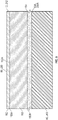
- Fig. 5 shows a cross sectional view of the customizable sections/portions 12, 212 coupled to the housing body 60, 260 according to one example of the present disclosure.
- the décor layer 152 e.g., including a laminate sheet material
- the substrate layer 150 e.g., including plywood, fiber board, or other composite or layered/paneled materials.
- the décor layer 152 includes the selected/customized colors, images, finishes, textures, etc. provided on its outward facing surface 152A.
- the décor layer 152 and the substrate layer 150 further can be coupled together by a reliable attachment, such as an adhesive, glue, etc.
- the substrate layer 150 also can be coupled/attached to the outer surface 60A, 260A of the housing body 60, 260 (e.g., including polymeric materials, such as plastics, elastomers, etc., or other suitable materials, such as metals or other composite or synthetic materials) by one or more adhesive layers 154, such as adhesive tape, glue, epoxy, etc. Additionally, or in alternative constructions, there will be no adhesive layer 154 and the surface 150B can be in face to face contact with or otherwise abut the surface 60A, 260A of the housing body 60, 260, with the customizable portions/sections 12, 212 being secured in place with fasteners, such as bolts, screws, etc., such as in connection assembly 300 shown in Fig.
- a latch, or pinned connection, etc. that facilitate relatively quick or easy removal of the substrate layer 150 from the housing 60, 260, and further can enable multiple attachments and removals, without substantial damage to the substrate layer and/or the housing, while also providing a substantially tight, secure connection/attachment between the substrate layer 150 and the housing body 60, 260, e.g., substantially preventing, reducing, or inhibiting displacement, dislodging, disconnection, dislocation, etc. of the customizable sections/portions from the housing during use of the return mechanism, such as due to vibrations, impacts, etc. at the bowling lane.
- FIG. 5 Although only one customizable portions/sections 12, 212 is shown in Fig. 5 , multiple (e.g., two or more) customizable portions/sections 12, 212 can be provided, such as two or more customizable portions/sections 12, 212 superposed over each other to provide for additional customization options, without departing from the scope of the present disclosure.
- the customizable, interchangeable sections or portions 12, 212 can be releasably coupled or otherwise fixed to the housing body 60 using any suitable mechanism or means, such as adhesives, snap-fit and/or other mechanical connections, etc., without departing from the scope of the present disclosure.
- the customizable, interchangeable sections or portions 12 can be at least partially received within one or more complementary grooves, cavities, or recessed portions 92/94 defined in/along the housing body 60, with one or more of such customizable, interchangeable portions ( i.e ., portion 82 as shown in Fig. 1B ) slidably or snap-fitted within a groove 92 defined along the top and/or side parts 66/68 of the housing body.
- customizable, interchangeable portions i.e ., part 90
- portions 82 and 90 can be substantially easily and relatively quickly attached and detached to the housing body 60.
- the customizable sections or portions 12 further can be coupled to each other and/or the housing body 60 using one or more fastening mechanism, connecting members, fasteners, adhesives, etc., without departing from the scope of the present disclosure.
- the return assembly 10 can include connecting or accent members 98 for coupling the sections/portions 12 together and/or to the housing body 60.
- the connections members 98 can include an elongated body 100 having slots or grooves 102/104 defined therealong, that are sized and/or configured to receive an end portion 106/108 of at least one of the customizable, interchangeable portions/sections 12.
- the body 100 can be formed from a metallic material, such as stainless steel, aluminum, etc., or other suitable material, such as plastic, rubber, wood, etc.
- the connecting members 98 can be positioned about the side parts of the housing body 60 and can connect the ends of sections 82 and 90.
- the ends 106/108 of the sections 82 and 90 can be slidably fit and frictionally engage within the grooves 102/104 to couple sections 82/90 together.
- the connecting member(s) 98 further can have one or more fasteners 110, such as screws, bolts, rivets, etc., for attaching the sections 12 thereto as shown in Fig. 7B .
- Fig. 8 further shows that the connecting or accent member(s) 98 can be configured to be adhered or bonded to at least one of the customizable sections 12.
- the connecting members 98 can have a bonding surface 112 that at least partially receives adhesive 114 to secure the connecting member 98 to at least a portion of the customizable/interchangeable sections 12.
- the adhesive 114 can include a double sided adhesive tape that can be attached or affixed to the bonding surface 114.
- the double sided adhesive tape can include double sided adhesive acrylic tapes, vinyl tapes, etc.
- the customizable bowling ball return mechanism 10 also can include a series of light sources 120, such as LEDs, light bulbs, etc. disposed therealong ( Figs. 7A and 7B ).
- Such light sources 120 can be arranged along the connecting members 98 or a portion of the customizable sections 12 or housing body 60 substantially adjacent the connecting members 98.
- the connecting members 98 can have a flange 122 or other projecting portion that can at least partially cover the light sources 120 ( Figs. 7A and 7B ), and the light sources 120 further can be positioned to illuminate at least a portion of the housing body 60, the customizable section 12, and/or an area adjacent the assembly 10.
- the light sources 120 can be positioned to at least partially reflect light off the flange 122 such that a portion 124 of the floor 28 substantially adjacent the housing 14 is illuminated.
- the light sources can be arranged along any portion of the assembly 10, e.g., the rails, support, inside the throat, etc., without departing from the scope of the present disclosure.
- the customizable sections 12 or housing body 60 additionally can have one or more translucent sections 126 that can be selectively illuminated by various ones of the light source(s) to provide various other visual effects.
- Figs. 6 , 9A and 9B show that the assembly 10 generally will have one or more end caps 130 that at least partially cover an end portion 132 of the connecting member 98, for example, to prevent injury to a bowler that may touch or bump into the connecting member 98.
- the end caps 130 can have an opening 134 that receives the end portions 132 of the connecting member 98 ( Fig. 9B ).
- the end caps 130 also can have a groove or slot 136 that receives at least a portion of the customizable sections 12.
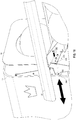
- Fig. 10 shows a connection assembly 300 for attachment of the customizable sections/portions 12 to the housing/housing portion(s) 14 according to one example of the present disclosure.
- the connection assembly 300 can include a plurality of brackets 302, 304 including one or more brackets 302 connected to the customizable portion/section 12 and one or more brackets 304 connected to the housing portion 14 and/or portions of the rail 20.
- the brackets 302, 304 further may have one or more holes, aperatures, etc.
- brackets 304/306 can include a space series of holes/apertures to facilitate adjustment of the connection assembly 300.
- Embodiments of the present disclosure also can provide a method or process for customer/user design or customization of a bowling ball return assembly. For example, in some variations, prior to purchasing the return assembly, customers can access a website, mobile application, etc., and design and customize colors, images, finishes, textures, etc. for each of the plurality of customizable, interchangeable sections 12, 212, e.g., design data or information can be received from customers and used to develop custom designs.
- the selected colors, finishes, images, textures, etc. can be provided (e.g., printed, painted, etc.) on the décor layer 152.
- the décor layer 152 then can be applied to/over the substrate layer 150 of the customizable, interchangeable section 12, 212.
- the entire customizable, interchangeable section 12, 212, including the substrate 150 and décor layer 152, can be formed, shaped, etc. to correspond to or at least partially cover at least a portion of the housing 60, 260 of the bowling ball return assembly, though the substrate layer 150 can be formed, shaped, etc. to at least partially cover/correspond to selected portion or portions of the housing 60, 260 prior to the application of the décor layer 152 thereto.
- the customizable, interchangeable sections 12, 212, with the customized design provide thereon, can be attached, coupled, etc. to the housing 14, 214 of the return assembly.
- a fasteners, brackets, and/or or other suitable connections mechanisms can be to couple to the sections 12, 212 the body 60, 260 of the housing 14, 214, although other reliable connector, such as adhesives, latching mechanisms, etc. can be used without departing from the scope of the present disclosure.
- a customer wants to later change/modify the design, e.g., to match updates to a bowling center, the customer can access the website, mobile application, etc. and design new customizable, interchangeable sections to replace the existing section 12, 212 to alter the design and look of the housing.
- a customer could purchase a kit with differently designed sections 12, 212 that can be easily interchangeable, for example, to correspond to specific themes, seasons, holidays, etc.
Landscapes
- Casings For Electric Apparatus (AREA)
- Toys (AREA)
Claims (15)
- Ensemble de retour de balle de bowling personnalisable (10, 200) pour une piste de bowling, comportant :une zone de récupération (18, 218), configurée pour recevoir une ou plusieurs balle(s) de bowling (22) pour la récupération par des joueurs de bowling à la piste de bowling ; etun boîtier (14, 214), agencé adjacent à la zone de récupération (18, 218), le boîtier (14, 214) comportant :un corps de boîtier (60, 260), ayant une partie supérieure (70, 256) et des parties latérales (66, 68) ; etun passage ou une décharge (16, 254), défini dans le corps de boîtier (60, 260), qui est calculé, dimensionné ou configuré pour permettre le passage d'une ou plusieurs balle(s) de bowling (22) à la zone de récupération (18, 218), dans lequel l'ensemble de retour de balle de bowling personnalisable (10, 200) est caractérisé par :
une pluralité de parties personnalisables, modulaires ou interchangeables (12, 212) d'une taille, dimension, forme ou configuration choisie, qui peuvent être couplées sélectivement au corps de boîtier (60, 260), et qui comportent une partie de face (80, 280) avec une ou plusieurs couleurs, images, représentations, graphiques, thèmes, finitions, textures choisis ou leurs combinaisons, prévus sur ceux-ci, dans lequel la pluralité de parties personnalisables, modulaires ou interchangeables (12, 212) comporte une paire des parties latérales opposées (86, 88), qui couvrent sensiblement les parties latérales (66, 68) du corps de boîtier (60, 260), et dans lequel la pluralité de parties personnalisables, modulaires ou interchangeables (12, 212) comporte en outre au moins un mécanisme de liaison (300), configuré pour coupler ensemble et / ou au corps de boîtier (60, 260) de manière amovible la pluralité de parties personnalisables, modulaires ou interchangeables (12, 212). - Ensemble de retour de balle de bowling personnalisable (10, 200) selon la revendication 1, dans lequel la pluralité de parties personnalisables, modulaires ou interchangeables (12, 212) comporte un matériau stratifié haute pression (152).
- Ensemble de retour de balle de bowling personnalisable (10, 200) selon la revendication 1, dans lequel la pluralité de parties personnalisables, modulaires ou interchangeables (12, 212) comporte une couche de substrat (150), qui est formée dans la taille, dimension, forme ou configuration choisie, et une couche décorative (152), qui comporte l'un ou plusieurs couleurs, images, représentations, graphiques, thèmes, finitions, textures choisis ou des combinaisons de ceux-ci, et est au moins partiellement reçue sur la couche de substrat (150).
- Ensemble de retour de balle de bowling personnalisable (10, 122) selon la revendication 3, dans lequel la couche de substrat (150) comporte au moins un parmi le contreplaqué, la plaque de fibre, les matériaux composites, les matériaux multicouches, ou des combinaison de ceux-ci, et dans lequel la couche décorative (152) comporte en outre au moins un parmi une feuille laminée (152), un matériau de papier, une matière plastique ou des combinaison de ceux-ci, appliqués sur la couche de substrat (150).
- Ensemble de retour de balle de bowling personnalisable (10, 200) selon la revendication 1, dans lequel la pluralité de parties personnalisables, modulaires ou interchangeables (12, 212) comporte une section supérieure (84), configurée pour s'étendre le long de et sensiblement couvrir la partie supérieure (70) du corps de boîtier (60).
- Ensemble de retour de balle de bowling personnalisable (10, 200) selon la revendication 1, dans lequel les parties latérales opposées (212) comportent une partie haute (212A) et une partie basse (212B) s'étendant de la partie haute (212A) vers une partie inférieure (260B) du corps de boîtier (260).
- Ensemble de retour de balle de bowling personnalisable (10, 200) selon la revendication 1, dans lequel la zone de récupération (18, 218) comporte un rail (20), configuré pour recevoir et supporter une pluralité de balles de bowling (22) retournées pour la récupération par les joueurs de bowling à la piste de bowling.
- Ensemble de retour de balle de bowling personnalisable (10, 200) selon la revendication 1, comportant en outre un mécanisme automatique de retour (24), au moins partiellement entouré par le corps de boîtier (60), dans lequel le mécanisme de retour (24) comporte des roues rotatives (44), configurées pour déplacer ou diriger des balles de bowling (22) retournées vers et à travers la décharge (16) dans le boîtier (14) pour décharger les balles de bowling (22) dans la zone de récupération (18).
- Ensemble de retour de balle de bowling personnalisable (10, 200) selon la revendication 1, comportant en outre une ou plusieurs voies (204) avec des surfaces de guidage (204A) pour diriger des balles de bowling (22) retournées à la zone de récupération (218).
- Boîtier (14, 214) personnalisable pour un retour de balles de bowling (10, 200) à une piste de bowling, comportant :un corps de boîtier (60, 260), ayant des parties latérales (66, 68) ; etun passage ou une décharge (16, 254), défini dans ou à travers le corps de boîtier (60, 260), qui est calculé, dimensionné ou configuré pour permettre le passage d'une ou plusieurs balle(s) de bowling (22) à une zone de récupération (18, 218), dans lequel le boîtier personnalisable est caractérisé par :
une pluralité de parties personnalisables, modulaires ou interchangeables (12, 212) d'une taille, dimension, forme ou configuration choisie, qui sont configurées pour être couplées sélectivement au corps de boîtier (60, 260), et qui comportent une surface ou face (80, 280) avec un ou plusieurs couleurs, images, représentations, graphiques, thèmes, finitions, textures choisis ou des combinaisons de ceux-ci, pourvus sur la surface ou la face (80, 280), dans lequel la pluralité de parties personnalisables, modulaires ou interchangeables (12, 212) est couplée de manière amovible au corps de boîtier (60, 260) en utilisant un ou plusieurs mécanisme(s) de fixation, des éléments de liaison, des moyens de fixation ou des adhésifs ou des combinaisons de ceux-ci, dans lequel la pluralité de parties personnalisables, modulaires ou interchangeables (12, 212) comporte une partie latérale (86, 88) couvrant sensiblement une partie latérale (66, 68) correspondante du corps de boîtier (60, 260). - Boîtier (14, 214) personnalisable selon la revendication 10, dans lequel la pluralité de parties personnalisables, modulaires ou interchangeables (12, 212) comporte un matériau stratifié haute pression (152) ; ou
dans lequel la pluralité de parties personnalisables, modulaires ou interchangeables (12, 212) comporte un matériau stratifié haute pression (152), et dans lequel la pluralité de parties personnalisables, modulaires ou interchangeables (12, 212) comporte une couche de substrat (150), qui comporte au moins un parmi un contreplaqué, une plaque de fibre, des matériaux composites, des matériaux multicouches ou des combinaisons de ceux-ci, et est formée dans la taille, dimension, forme ou configuration choisie, et une couche décorative (152), qui comporte au moins un parmi une feuille laminée, un matériau de papier, une matière plastique ou des combinaisons de ceux-ci, avec un ou plusieurs couleurs, images, représentations, graphiques, thèmes, finitions, textures choisis ou des combinaisons de ceux-ci prévus le long d'une surface (80, 280) de ceux-ci, et est au moins partiellement reçu sur la couche de substrat (150). - Boîtier (14, 214) personnalisable selon la revendication 10, dans lequel la pluralité de parties personnalisables, modulaires ou interchangeables (12, 212) comporte au moins une section supérieure (82) remplaçable comportant une part supérieure (84), configurée pour s'étendre le long de et couvrir sensiblement une partie supérieure (70) du corps de boîtier (60), et une paire des parties latérales opposées (86, 88, 212) s'étendant vers le bas à partir de la part supérieure (84), et sensiblement couvrant des parties latérales (66, 68) du corps de boîtier (60).
- Boîtier (14, 214) personnalisable selon la revendication 10, dans lequel la zone de récupération (18, 218) comporte un rail (20), configuré pour recevoir et supporter une pluralité de balles de bowling (22) retournées pour la récupération par les joueurs de bowling à la piste de bowling.
- Boîtier (14, 214) personnalisable selon la revendication 10, comportant en outre un ou plusieurs éléments de liaison (90), qui sont configurés pour coupler ensemble ou et / ou au moins à une partie du corps de boîtier (60, 260) de manière amovible la pluralité de parties personnalisables, modulaires ou interchangeables.
- Boîtier (14, 214) personnalisable selon la revendication 10, dans lequel l'une ou plusieurs balle(s) de bowling (22) comporte(nt) des balles à dix broches, des balles plus petites (duckpin), des balles à cinq broches, ou des balles aux chandelles (candlepin).
Applications Claiming Priority (1)
| Application Number | Priority Date | Filing Date | Title |
|---|---|---|---|
| US201862660483P | 2018-04-20 | 2018-04-20 |
Publications (2)
| Publication Number | Publication Date |
|---|---|
| EP3556442A1 EP3556442A1 (fr) | 2019-10-23 |
| EP3556442B1 true EP3556442B1 (fr) | 2021-03-24 |
Family
ID=66248587
Family Applications (1)
| Application Number | Title | Priority Date | Filing Date |
|---|---|---|---|
| EP19170543.3A Active EP3556442B1 (fr) | 2018-04-20 | 2019-04-23 | Ensemble de retour de balle de bowling |
Country Status (3)
| Country | Link |
|---|---|
| US (1) | US20190321714A1 (fr) |
| EP (1) | EP3556442B1 (fr) |
| JP (1) | JP2019188145A (fr) |
Families Citing this family (6)
| Publication number | Priority date | Publication date | Assignee | Title |
|---|---|---|---|---|
| USD891550S1 (en) * | 2018-04-20 | 2020-07-28 | Brunswick Bowling Products Llc | Bowling ball return assembly |
| US10888765B2 (en) * | 2018-09-19 | 2021-01-12 | Bradley N. Duke | Bowling ball ramp including embedded lighting and/or sound |
| USD891551S1 (en) * | 2019-04-19 | 2020-07-28 | Brunswick Bowling Products Llc | Bowling ball return assembly |
| USD891552S1 (en) * | 2019-04-19 | 2020-07-28 | Brunswick Bowling Products Llc | Bowling ball return assembly |
| WO2023249948A1 (fr) * | 2022-06-22 | 2023-12-28 | Dig Holding & Trust Iv, Llc | Dispositif de lancement de boules de bowling |
| USD1004025S1 (en) * | 2023-06-13 | 2023-11-07 | Lifelong Worldwide Bowling, Inc. | Ball lift accessory for a bowling alley ball return |
Family Cites Families (5)
| Publication number | Priority date | Publication date | Assignee | Title |
|---|---|---|---|---|
| US4406456A (en) * | 1979-05-01 | 1983-09-27 | Brunswick Corporation | Method of resurfacing a bowling lane and product of said method |
| US5624322A (en) * | 1996-04-23 | 1997-04-29 | Amf Bowling, Inc. | Bowling alley return and storage rack |
| CN1168293A (zh) * | 1996-06-13 | 1997-12-24 | 董国良 | 保龄球成套设备 |
| US20050020368A1 (en) * | 1998-04-15 | 2005-01-27 | Burkholder Roy A. | Bowling lane advertising and method |
| US8435128B2 (en) * | 2009-02-03 | 2013-05-07 | Brunswick Bowling & Billards Corporation | Bowling lane with mural image |
-
2019
- 2019-04-19 JP JP2019080220A patent/JP2019188145A/ja active Pending
- 2019-04-19 US US16/389,350 patent/US20190321714A1/en not_active Abandoned
- 2019-04-23 EP EP19170543.3A patent/EP3556442B1/fr active Active
Non-Patent Citations (1)
| Title |
|---|
| None * |
Also Published As
| Publication number | Publication date |
|---|---|
| US20190321714A1 (en) | 2019-10-24 |
| EP3556442A1 (fr) | 2019-10-23 |
| JP2019188145A (ja) | 2019-10-31 |
Similar Documents
| Publication | Publication Date | Title |
|---|---|---|
| EP3556442B1 (fr) | Ensemble de retour de balle de bowling | |
| US5529541A (en) | Ultraviolet light illuminated bowling lane | |
| US8419140B2 (en) | Chambered cremation URN memorial with attached or integrated electronic imaging device | |
| BRPI0519338A2 (pt) | painel de piso e mÉtodo para fabricar um painel de piso | |
| US20130095273A1 (en) | Decorative and removable bannister, railing and spindle covers | |
| CA2105247C (fr) | Monument funeraire en pierre et bronze | |
| US20070278468A1 (en) | Novel modular molded frame with interchangeable design panels for vinyl fencing and its method of fabrication | |
| US10568420B1 (en) | Game table | |
| US6840868B2 (en) | Glow-in-the-dark film for bowling lanes | |
| EP1586724B1 (fr) | Mur de piscine | |
| US20050086844A1 (en) | Three-dimensional frame | |
| Miles | Contemporary Retail Design: A Store Planner's Handbook | |
| CN204541518U (zh) | 收银台 | |
| Schittich | Interior spaces: space, light, materials | |
| Avery | The house of Alessandro Vittoria reconstructed | |
| FR2584443A1 (fr) | Element commemoratif pour tombe | |
| GB2088222A (en) | Trim for a games table | |
| NL2017724B1 (nl) | Werkwijze voor het vervaardigen van een trap alsmede een trap verkregen met de werkwijze | |
| BUILDING | SHS inside, is an unusual feature | |
| Desmas et al. | 2. Pair of cabinets | |
| WO2019041295A1 (fr) | Abattant de toilettes en pierre et siège | |
| Iljadica | Classifying art in diverse legal regimes: the function-aesthetic divide and the public interest | |
| KR200428351Y1 (ko) | 현관바닥 장식필름 판 장치. | |
| Desmas et al. | 6. Commode | |
| Sturgis | A Review of the Work of George B. Post... |
Legal Events
| Date | Code | Title | Description |
|---|---|---|---|
| PUAI | Public reference made under article 153(3) epc to a published international application that has entered the european phase |
Free format text: ORIGINAL CODE: 0009012 |
|
| STAA | Information on the status of an ep patent application or granted ep patent |
Free format text: STATUS: THE APPLICATION HAS BEEN PUBLISHED |
|
| AK | Designated contracting states |
Kind code of ref document: A1 Designated state(s): AL AT BE BG CH CY CZ DE DK EE ES FI FR GB GR HR HU IE IS IT LI LT LU LV MC MK MT NL NO PL PT RO RS SE SI SK SM TR |
|
| AX | Request for extension of the european patent |
Extension state: BA ME |
|
| STAA | Information on the status of an ep patent application or granted ep patent |
Free format text: STATUS: REQUEST FOR EXAMINATION WAS MADE |
|
| 17P | Request for examination filed |
Effective date: 20200421 |
|
| RBV | Designated contracting states (corrected) |
Designated state(s): AL AT BE BG CH CY CZ DE DK EE ES FI FR GB GR HR HU IE IS IT LI LT LU LV MC MK MT NL NO PL PT RO RS SE SI SK SM TR |
|
| GRAP | Despatch of communication of intention to grant a patent |
Free format text: ORIGINAL CODE: EPIDOSNIGR1 |
|
| STAA | Information on the status of an ep patent application or granted ep patent |
Free format text: STATUS: GRANT OF PATENT IS INTENDED |
|
| INTG | Intention to grant announced |
Effective date: 20201013 |
|
| GRAS | Grant fee paid |
Free format text: ORIGINAL CODE: EPIDOSNIGR3 |
|
| GRAA | (expected) grant |
Free format text: ORIGINAL CODE: 0009210 |
|
| STAA | Information on the status of an ep patent application or granted ep patent |
Free format text: STATUS: THE PATENT HAS BEEN GRANTED |
|
| AK | Designated contracting states |
Kind code of ref document: B1 Designated state(s): AL AT BE BG CH CY CZ DE DK EE ES FI FR GB GR HR HU IE IS IT LI LT LU LV MC MK MT NL NO PL PT RO RS SE SI SK SM TR |
|
| REG | Reference to a national code |
Ref country code: GB Ref legal event code: FG4D |
|
| REG | Reference to a national code |
Ref country code: CH Ref legal event code: EP |
|
| REG | Reference to a national code |
Ref country code: IE Ref legal event code: FG4D |
|
| REG | Reference to a national code |
Ref country code: DE Ref legal event code: R096 Ref document number: 602019003335 Country of ref document: DE Ref country code: AT Ref legal event code: REF Ref document number: 1373902 Country of ref document: AT Kind code of ref document: T Effective date: 20210415 |
|
| REG | Reference to a national code |
Ref country code: NL Ref legal event code: FP |
|
| REG | Reference to a national code |
Ref country code: SE Ref legal event code: TRGR |
|
| REG | Reference to a national code |
Ref country code: LT Ref legal event code: MG9D |
|
| PG25 | Lapsed in a contracting state [announced via postgrant information from national office to epo] |
Ref country code: BG Free format text: LAPSE BECAUSE OF FAILURE TO SUBMIT A TRANSLATION OF THE DESCRIPTION OR TO PAY THE FEE WITHIN THE PRESCRIBED TIME-LIMIT Effective date: 20210624 Ref country code: HR Free format text: LAPSE BECAUSE OF FAILURE TO SUBMIT A TRANSLATION OF THE DESCRIPTION OR TO PAY THE FEE WITHIN THE PRESCRIBED TIME-LIMIT Effective date: 20210324 Ref country code: GR Free format text: LAPSE BECAUSE OF FAILURE TO SUBMIT A TRANSLATION OF THE DESCRIPTION OR TO PAY THE FEE WITHIN THE PRESCRIBED TIME-LIMIT Effective date: 20210625 Ref country code: FI Free format text: LAPSE BECAUSE OF FAILURE TO SUBMIT A TRANSLATION OF THE DESCRIPTION OR TO PAY THE FEE WITHIN THE PRESCRIBED TIME-LIMIT Effective date: 20210324 Ref country code: NO Free format text: LAPSE BECAUSE OF FAILURE TO SUBMIT A TRANSLATION OF THE DESCRIPTION OR TO PAY THE FEE WITHIN THE PRESCRIBED TIME-LIMIT Effective date: 20210624 |
|
| PG25 | Lapsed in a contracting state [announced via postgrant information from national office to epo] |
Ref country code: RS Free format text: LAPSE BECAUSE OF FAILURE TO SUBMIT A TRANSLATION OF THE DESCRIPTION OR TO PAY THE FEE WITHIN THE PRESCRIBED TIME-LIMIT Effective date: 20210324 Ref country code: LV Free format text: LAPSE BECAUSE OF FAILURE TO SUBMIT A TRANSLATION OF THE DESCRIPTION OR TO PAY THE FEE WITHIN THE PRESCRIBED TIME-LIMIT Effective date: 20210324 |
|
| REG | Reference to a national code |
Ref country code: AT Ref legal event code: MK05 Ref document number: 1373902 Country of ref document: AT Kind code of ref document: T Effective date: 20210324 |
|
| PG25 | Lapsed in a contracting state [announced via postgrant information from national office to epo] |
Ref country code: LT Free format text: LAPSE BECAUSE OF FAILURE TO SUBMIT A TRANSLATION OF THE DESCRIPTION OR TO PAY THE FEE WITHIN THE PRESCRIBED TIME-LIMIT Effective date: 20210324 Ref country code: CZ Free format text: LAPSE BECAUSE OF FAILURE TO SUBMIT A TRANSLATION OF THE DESCRIPTION OR TO PAY THE FEE WITHIN THE PRESCRIBED TIME-LIMIT Effective date: 20210324 Ref country code: EE Free format text: LAPSE BECAUSE OF FAILURE TO SUBMIT A TRANSLATION OF THE DESCRIPTION OR TO PAY THE FEE WITHIN THE PRESCRIBED TIME-LIMIT Effective date: 20210324 Ref country code: AT Free format text: LAPSE BECAUSE OF FAILURE TO SUBMIT A TRANSLATION OF THE DESCRIPTION OR TO PAY THE FEE WITHIN THE PRESCRIBED TIME-LIMIT Effective date: 20210324 Ref country code: SM Free format text: LAPSE BECAUSE OF FAILURE TO SUBMIT A TRANSLATION OF THE DESCRIPTION OR TO PAY THE FEE WITHIN THE PRESCRIBED TIME-LIMIT Effective date: 20210324 |
|
| PG25 | Lapsed in a contracting state [announced via postgrant information from national office to epo] |
Ref country code: IS Free format text: LAPSE BECAUSE OF FAILURE TO SUBMIT A TRANSLATION OF THE DESCRIPTION OR TO PAY THE FEE WITHIN THE PRESCRIBED TIME-LIMIT Effective date: 20210724 Ref country code: PT Free format text: LAPSE BECAUSE OF FAILURE TO SUBMIT A TRANSLATION OF THE DESCRIPTION OR TO PAY THE FEE WITHIN THE PRESCRIBED TIME-LIMIT Effective date: 20210726 Ref country code: RO Free format text: LAPSE BECAUSE OF FAILURE TO SUBMIT A TRANSLATION OF THE DESCRIPTION OR TO PAY THE FEE WITHIN THE PRESCRIBED TIME-LIMIT Effective date: 20210324 Ref country code: SK Free format text: LAPSE BECAUSE OF FAILURE TO SUBMIT A TRANSLATION OF THE DESCRIPTION OR TO PAY THE FEE WITHIN THE PRESCRIBED TIME-LIMIT Effective date: 20210324 Ref country code: PL Free format text: LAPSE BECAUSE OF FAILURE TO SUBMIT A TRANSLATION OF THE DESCRIPTION OR TO PAY THE FEE WITHIN THE PRESCRIBED TIME-LIMIT Effective date: 20210324 |
|
| PG25 | Lapsed in a contracting state [announced via postgrant information from national office to epo] |
Ref country code: LU Free format text: LAPSE BECAUSE OF NON-PAYMENT OF DUE FEES Effective date: 20210423 |
|
| REG | Reference to a national code |
Ref country code: DE Ref legal event code: R097 Ref document number: 602019003335 Country of ref document: DE |
|
| REG | Reference to a national code |
Ref country code: BE Ref legal event code: MM Effective date: 20210430 |
|
| PG25 | Lapsed in a contracting state [announced via postgrant information from national office to epo] |
Ref country code: MC Free format text: LAPSE BECAUSE OF FAILURE TO SUBMIT A TRANSLATION OF THE DESCRIPTION OR TO PAY THE FEE WITHIN THE PRESCRIBED TIME-LIMIT Effective date: 20210324 Ref country code: AL Free format text: LAPSE BECAUSE OF FAILURE TO SUBMIT A TRANSLATION OF THE DESCRIPTION OR TO PAY THE FEE WITHIN THE PRESCRIBED TIME-LIMIT Effective date: 20210324 Ref country code: DK Free format text: LAPSE BECAUSE OF FAILURE TO SUBMIT A TRANSLATION OF THE DESCRIPTION OR TO PAY THE FEE WITHIN THE PRESCRIBED TIME-LIMIT Effective date: 20210324 Ref country code: ES Free format text: LAPSE BECAUSE OF FAILURE TO SUBMIT A TRANSLATION OF THE DESCRIPTION OR TO PAY THE FEE WITHIN THE PRESCRIBED TIME-LIMIT Effective date: 20210324 |
|
| PLBE | No opposition filed within time limit |
Free format text: ORIGINAL CODE: 0009261 |
|
| STAA | Information on the status of an ep patent application or granted ep patent |
Free format text: STATUS: NO OPPOSITION FILED WITHIN TIME LIMIT |
|
| PG25 | Lapsed in a contracting state [announced via postgrant information from national office to epo] |
Ref country code: SI Free format text: LAPSE BECAUSE OF FAILURE TO SUBMIT A TRANSLATION OF THE DESCRIPTION OR TO PAY THE FEE WITHIN THE PRESCRIBED TIME-LIMIT Effective date: 20210324 |
|
| 26N | No opposition filed |
Effective date: 20220104 |
|
| PG25 | Lapsed in a contracting state [announced via postgrant information from national office to epo] |
Ref country code: IE Free format text: LAPSE BECAUSE OF NON-PAYMENT OF DUE FEES Effective date: 20210423 |
|
| PG25 | Lapsed in a contracting state [announced via postgrant information from national office to epo] |
Ref country code: IS Free format text: LAPSE BECAUSE OF FAILURE TO SUBMIT A TRANSLATION OF THE DESCRIPTION OR TO PAY THE FEE WITHIN THE PRESCRIBED TIME-LIMIT Effective date: 20210724 |
|
| PG25 | Lapsed in a contracting state [announced via postgrant information from national office to epo] |
Ref country code: BE Free format text: LAPSE BECAUSE OF NON-PAYMENT OF DUE FEES Effective date: 20210430 |
|
| REG | Reference to a national code |
Ref country code: CH Ref legal event code: PL |
|
| PG25 | Lapsed in a contracting state [announced via postgrant information from national office to epo] |
Ref country code: LI Free format text: LAPSE BECAUSE OF NON-PAYMENT OF DUE FEES Effective date: 20220430 Ref country code: CH Free format text: LAPSE BECAUSE OF NON-PAYMENT OF DUE FEES Effective date: 20220430 |
|
| P01 | Opt-out of the competence of the unified patent court (upc) registered |
Effective date: 20230523 |
|
| PG25 | Lapsed in a contracting state [announced via postgrant information from national office to epo] |
Ref country code: CY Free format text: LAPSE BECAUSE OF FAILURE TO SUBMIT A TRANSLATION OF THE DESCRIPTION OR TO PAY THE FEE WITHIN THE PRESCRIBED TIME-LIMIT Effective date: 20210324 |
|
| PG25 | Lapsed in a contracting state [announced via postgrant information from national office to epo] |
Ref country code: HU Free format text: LAPSE BECAUSE OF FAILURE TO SUBMIT A TRANSLATION OF THE DESCRIPTION OR TO PAY THE FEE WITHIN THE PRESCRIBED TIME-LIMIT; INVALID AB INITIO Effective date: 20190423 |
|
| PG25 | Lapsed in a contracting state [announced via postgrant information from national office to epo] |
Ref country code: MK Free format text: LAPSE BECAUSE OF FAILURE TO SUBMIT A TRANSLATION OF THE DESCRIPTION OR TO PAY THE FEE WITHIN THE PRESCRIBED TIME-LIMIT Effective date: 20210324 |
|
| PGFP | Annual fee paid to national office [announced via postgrant information from national office to epo] |
Ref country code: GB Payment date: 20240429 Year of fee payment: 6 |
|
| PGFP | Annual fee paid to national office [announced via postgrant information from national office to epo] |
Ref country code: FR Payment date: 20240425 Year of fee payment: 6 |
|
| PGFP | Annual fee paid to national office [announced via postgrant information from national office to epo] |
Ref country code: SE Payment date: 20240427 Year of fee payment: 6 |
|
| PG25 | Lapsed in a contracting state [announced via postgrant information from national office to epo] |
Ref country code: MT Free format text: LAPSE BECAUSE OF FAILURE TO SUBMIT A TRANSLATION OF THE DESCRIPTION OR TO PAY THE FEE WITHIN THE PRESCRIBED TIME-LIMIT Effective date: 20210324 |
|
| PGFP | Annual fee paid to national office [announced via postgrant information from national office to epo] |
Ref country code: NL Payment date: 20250427 Year of fee payment: 7 |
|
| PGFP | Annual fee paid to national office [announced via postgrant information from national office to epo] |
Ref country code: DE Payment date: 20250429 Year of fee payment: 7 |
|
| PGFP | Annual fee paid to national office [announced via postgrant information from national office to epo] |
Ref country code: IT Payment date: 20250422 Year of fee payment: 7 |
|
| REG | Reference to a national code |
Ref country code: SE Ref legal event code: EUG |
|
| PG25 | Lapsed in a contracting state [announced via postgrant information from national office to epo] |
Ref country code: TR Free format text: LAPSE BECAUSE OF FAILURE TO SUBMIT A TRANSLATION OF THE DESCRIPTION OR TO PAY THE FEE WITHIN THE PRESCRIBED TIME-LIMIT Effective date: 20210324 |
|
| GBPC | Gb: european patent ceased through non-payment of renewal fee |
Effective date: 20250423 |
|
| PG25 | Lapsed in a contracting state [announced via postgrant information from national office to epo] |
Ref country code: GB Free format text: LAPSE BECAUSE OF NON-PAYMENT OF DUE FEES Effective date: 20250423 |
|
| PG25 | Lapsed in a contracting state [announced via postgrant information from national office to epo] |
Ref country code: FR Free format text: LAPSE BECAUSE OF NON-PAYMENT OF DUE FEES Effective date: 20250430 |
|
| PG25 | Lapsed in a contracting state [announced via postgrant information from national office to epo] |
Ref country code: SE Free format text: LAPSE BECAUSE OF NON-PAYMENT OF DUE FEES Effective date: 20250424 |