EP3556449A1 - Élément filtrant, séparateur à coalescence et son procédé de fabrication ainsi que son utilisation - Google Patents
Élément filtrant, séparateur à coalescence et son procédé de fabrication ainsi que son utilisation Download PDFInfo
- Publication number
- EP3556449A1 EP3556449A1 EP19169400.9A EP19169400A EP3556449A1 EP 3556449 A1 EP3556449 A1 EP 3556449A1 EP 19169400 A EP19169400 A EP 19169400A EP 3556449 A1 EP3556449 A1 EP 3556449A1
- Authority
- EP
- European Patent Office
- Prior art keywords
- filter
- filter element
- filter layer
- layer
- support body
- Prior art date
- Legal status (The legal status is an assumption and is not a legal conclusion. Google has not performed a legal analysis and makes no representation as to the accuracy of the status listed.)
- Granted
Links
Images


Classifications
-
- B—PERFORMING OPERATIONS; TRANSPORTING
- B01—PHYSICAL OR CHEMICAL PROCESSES OR APPARATUS IN GENERAL
- B01D—SEPARATION
- B01D29/00—Filters with filtering elements stationary during filtration, e.g. pressure or suction filters, not covered by groups B01D24/00 - B01D27/00; Filtering elements therefor
- B01D29/11—Filters with filtering elements stationary during filtration, e.g. pressure or suction filters, not covered by groups B01D24/00 - B01D27/00; Filtering elements therefor with bag, cage, hose, tube, sleeve or like filtering elements
- B01D29/13—Supported filter elements
- B01D29/23—Supported filter elements arranged for outward flow filtration
- B01D29/27—Filter bags
-
- B—PERFORMING OPERATIONS; TRANSPORTING
- B01—PHYSICAL OR CHEMICAL PROCESSES OR APPARATUS IN GENERAL
- B01D—SEPARATION
- B01D29/00—Filters with filtering elements stationary during filtration, e.g. pressure or suction filters, not covered by groups B01D24/00 - B01D27/00; Filtering elements therefor
- B01D29/11—Filters with filtering elements stationary during filtration, e.g. pressure or suction filters, not covered by groups B01D24/00 - B01D27/00; Filtering elements therefor with bag, cage, hose, tube, sleeve or like filtering elements
- B01D29/117—Filters with filtering elements stationary during filtration, e.g. pressure or suction filters, not covered by groups B01D24/00 - B01D27/00; Filtering elements therefor with bag, cage, hose, tube, sleeve or like filtering elements arranged for outward flow filtration
- B01D29/118—Filters with filtering elements stationary during filtration, e.g. pressure or suction filters, not covered by groups B01D24/00 - B01D27/00; Filtering elements therefor with bag, cage, hose, tube, sleeve or like filtering elements arranged for outward flow filtration open-ended
-
- B—PERFORMING OPERATIONS; TRANSPORTING
- B01—PHYSICAL OR CHEMICAL PROCESSES OR APPARATUS IN GENERAL
- B01D—SEPARATION
- B01D29/00—Filters with filtering elements stationary during filtration, e.g. pressure or suction filters, not covered by groups B01D24/00 - B01D27/00; Filtering elements therefor
- B01D29/11—Filters with filtering elements stationary during filtration, e.g. pressure or suction filters, not covered by groups B01D24/00 - B01D27/00; Filtering elements therefor with bag, cage, hose, tube, sleeve or like filtering elements
- B01D29/13—Supported filter elements
- B01D29/23—Supported filter elements arranged for outward flow filtration
- B01D29/25—Supported filter elements arranged for outward flow filtration open-ended the arrival of the mixture to be filtered and the discharge of the concentrated mixture are situated on both opposite sides of the filtering element
-
- B—PERFORMING OPERATIONS; TRANSPORTING
- B01—PHYSICAL OR CHEMICAL PROCESSES OR APPARATUS IN GENERAL
- B01D—SEPARATION
- B01D29/00—Filters with filtering elements stationary during filtration, e.g. pressure or suction filters, not covered by groups B01D24/00 - B01D27/00; Filtering elements therefor
- B01D29/50—Filters with filtering elements stationary during filtration, e.g. pressure or suction filters, not covered by groups B01D24/00 - B01D27/00; Filtering elements therefor with multiple filtering elements, characterised by their mutual disposition
- B01D29/56—Filters with filtering elements stationary during filtration, e.g. pressure or suction filters, not covered by groups B01D24/00 - B01D27/00; Filtering elements therefor with multiple filtering elements, characterised by their mutual disposition in series connection
- B01D29/58—Filters with filtering elements stationary during filtration, e.g. pressure or suction filters, not covered by groups B01D24/00 - B01D27/00; Filtering elements therefor with multiple filtering elements, characterised by their mutual disposition in series connection arranged concentrically or coaxially
-
- B—PERFORMING OPERATIONS; TRANSPORTING
- B01—PHYSICAL OR CHEMICAL PROCESSES OR APPARATUS IN GENERAL
- B01D—SEPARATION
- B01D36/00—Filter circuits or combinations of filters with other separating devices
- B01D36/003—Filters in combination with devices for the removal of liquids
-
- C—CHEMISTRY; METALLURGY
- C10—PETROLEUM, GAS OR COKE INDUSTRIES; TECHNICAL GASES CONTAINING CARBON MONOXIDE; FUELS; LUBRICANTS; PEAT
- C10G—CRACKING HYDROCARBON OILS; PRODUCTION OF LIQUID HYDROCARBON MIXTURES, e.g. BY DESTRUCTIVE HYDROGENATION, OLIGOMERISATION, POLYMERISATION; RECOVERY OF HYDROCARBON OILS FROM OIL-SHALE, OIL-SAND, OR GASES; REFINING MIXTURES MAINLY CONSISTING OF HYDROCARBONS; REFORMING OF NAPHTHA; MINERAL WAXES
- C10G33/00—Dewatering or demulsification of hydrocarbon oils
- C10G33/06—Dewatering or demulsification of hydrocarbon oils with mechanical means, e.g. by filtration
-
- B—PERFORMING OPERATIONS; TRANSPORTING
- B01—PHYSICAL OR CHEMICAL PROCESSES OR APPARATUS IN GENERAL
- B01D—SEPARATION
- B01D2201/00—Details relating to filtering apparatus
- B01D2201/18—Filters characterised by the openings or pores
- B01D2201/188—Multiple filtering elements having filtering areas of different size
Definitions
- the invention relates to a filter element for a coalescer according to the preamble of claim 1, a coalescer according to claim 10, a method for producing a filter element according to claim 12, and a manufacturing device for carrying out the method according to claim 13.
- Coalescence separators serve to separate a medium from a medium to be purified. For this purpose, they have as a filter element to a material that is difficult to penetrate for the deposited medium than for the medium to be cleaned. In this way, growing within the filter element growing droplets of the deposited medium, which reach as soon as they reach the outlet side of the filter element due to their size and a density difference to be cleaned medium or ascend and collectable in a designated plenum. This collection space can then be emptied.
- a coalescence separator can be produced in that a perforated support tube or perforated support body forms a winding core for glass fiber mats of different porosity or glass fiber reinforced polyamide mats, so that the mats wound on the perforated support tube in multiple layers forms a filter element.
- the support tube is then closed at its ends with a first end plate, which forms an inlet and a sealing second end plate.
- the Koaleszenzabscheider is now used to introduce free water containing hydrocarbon through the inlet into the support tube and to convey from the inside to the outside through the filter element. In this case, the free water is retained and forms drops which, as soon as they reach the outer surface of the filter element, run downwards.
- a similar wrapping of a support core with a mat-shaped glass fiber material to form a filter element or Koaleszenzabscheiders is also in DE 21 26 080 C3 and DE 11 13 783 B described.
- a disadvantage of these embodiments is that the winding process requires expensive machines, because the porosity of the filter element depends on the compression of the winding. Also, the production quantities on the winding machines are low, because the winding is time-consuming. This makes the coalescer expensive to manufacture. Finally, the filter element made by winding can not be replaced by a user. Not even a simple separation of the materials for the purpose of recycling succeeds. The latter partly because the wound mats are treated with environmentally harmful phenolic resins to make them hydrophilic.
- the object of the invention is therefore to overcome the disadvantages of the prior art and to provide a solution that leads to a cost-effective, easy to produce and environmentally friendly Koaleszenzabscheider that also can be well maintained and disposed of.
- the invention relates to a filter element for a coalescence separator, with or consisting of a filter layer system comprising at least a first filter layer layer of a nonwoven material wherein the filter layer system is designed as a filter sock, which has the shape of an elongate hollow body.
- the filter elements can be manufactured and stored separately from supporting bodies.
- the filter sock-like filter element is optionally interchangeable, preferably non-destructive by mounting on and pulling off a support body. This opens up a spare part and service market for filter elements and coalescence separators.
- the filter part is easily recyclable.
- the filter sock-like filter element can also be firmly sealed sitting on the support body. As a result, no fluid in the edge region can pass through the filter element, without being filtered.
- the filter sock has two longitudinal ends that are open.
- the filter sock can be pushed onto a support body at one end, while a mounting core protrudes from the direction of the other end into the filter element. This allows easy installation by the filter sock from the mounting core on the support tube is pushed.
- a hollow mounting core can be used, which is first pushed over the support body with the filter sock. By pulling out the mounting core, the filter sock is then placed on the support body.
- the filter sock preferably has a length which corresponds to at least three times, more preferably at least four times and particularly preferably at least five times the diameter of the filter sock. This results in a slim design.
- the filter sock should have a hollow cylindrical shape. This allows it to be positively mounted on a cylindrical outer wall of a support body.
- the filter sock should have an elasticity, in particular elasticity of expansion, in particular in the circumferential direction. This facilitates mounting on a support body. In conjunction with the optional support body described later, it makes sense if the filter sock in the unloaded state has an inner diameter which is less than or equal to the outer diameter of the support body, and in the elastically stretched state can reach an inner diameter which is greater than the outer diameter of the support body is.
- the filter sock sits positively on the support body. At the same time it can be mounted on the support body by stretching as part of its elasticity.
- the filter sock is shapeless. This somewhat resembles a garment stocking and has the advantage that during assembly and storage no damage such as wrinkles can occur. In contrast to a shapely filter sock, wrinkle elements have a structural inherent stability that is sensitive to kinking and wrinkles.
- the filter element of the filter sock is made seamless.
- the separation effect of the filter element over the entire circumference is the same. This can be implemented according to the method, for example by blowing nonwoven fibers through an annular mask according to an extrusion process.
- the filter sock is formed with a longitudinal seam which connects at least the first filter layer layer, and preferably the filter layer system in the circumferential direction.
- the longitudinal seam is a weld.
- the filter element contains no foreign substances such as phenolic resins and is easily recyclable.
- the longitudinal seam facing outward, this in particular by the fact that the filter layer system has two circumferential ends, which are connected to each other facing outward. This allows a simple and precise connection with simply folded non-woven mat.
- a linear longitudinal seam, in particular parallel to the axis of the filter sock, is to be preferred. This is particularly easy to produce.
- the fleece is spirally wound around the support body and welded together at the joints.
- the filter layer system has at least one second filter layer layer of a nonwoven material, wherein the second filter layer layer is arranged adjacent to the first filter layer layer. Due to the multi-stage structure of the filter layer system, the coalescence effect can be increased.
- the second filter layer layer should have a porosity that deviates from a porosity of the first filter layer layer.
- the optional longitudinal seam connects all the filter layer layers of the filter layer system together. This is only a compound to produce, and the nonwoven materials can initially stacked, then turned over and then connected.
- the filter layer layers should at least substantially or completely loose on each other. Thus, no joining techniques are necessary, especially no phenolic resins or the filter area reducing compounds.
- a cost-effective production and stock keeping succeeds in a variant in which at least one of the filter layer layers is produced endlessly, and preferably all of the filter layer layers are produced endlessly.
- At least one of the filter layer layers should be hydrophobic.
- the deposition of water can also be supported by the fact that at least one of the filter layer layers is hydrophilic.
- the filter layer layers each have a porosity, wherein the porosity of the filter layer layers decreases from the inside to the outside. This supports coalescence.
- the invention also relates to a coalescer with a filter element, as described above and below, and with an inlet, which opens into a support body with outlet openings, wherein the filter element is mounted on the support body, in particular such that it downstream of the Outlet openings is arranged.
- the advantage of such a Koaleszenzabscheiders is that the production is simple because no winding machine for the production of the filter element is required.
- the filter element may optionally be designed to be exchangeable by being pulled on and off from the support body. This opens up a spare part and service market. This makes the coalescence separator also easy to recycle.
- the filter sock-like filter element can also be firmly sealed sitting on the support body. As a result, no fluid in the edge region can pass through the filter element, without being filtered.
- the seal may be formed, for example, in the range of the optional end plates specified below.
- the support body should be tubular, wherein the inlet is arranged at a first end and / or a second end of the tubular support body, and wherein the outlet openings are formed in a lateral surface of the tubular support body.
- the support body may be a perforated, perforated or porous tubular body.
- the support body is hollow cylindrical.
- the support body preferably has a length which corresponds to at least three times, more preferably at least four times and more preferably at least five times the diameter of the support body. This results in a slim design. It can be arranged adjacent to each other in a small space correspondingly numerous Koaleszensabscheider. This results in a high filter surface in a small space.
- Inexpensive and environmentally friendly is a closer embodiment, according to which the first filter layer layer sits at least substantially or completely loose on the support body.
- the filter layer system designed as a filter sock should be sealed in the region of the first and second end in a fluid-tight manner relative to the tubular support body. As a result, all the fluid must pass through the filter element to leave the Koaleszenzabscheider.
- At least two of the filter layer layers are simultaneously applied to the support body.
- the final assembly effort of the Auf ists is low.
- the inlet is formed in a first end plate which closes the tubular support body at the first end (in particular with the exception of the inlet).
- the first end plate can be manufactured separately and attached to the support body after mounting the filter element.
- the tubular support body should be closed at the second end with a second end plate.
- This second end plate may have an inlet or be designed to be fluid-tight.
- a prefilter element can optionally be arranged in the support body, e.g. a folding part or a folded filter.
- a folding part forms a particularly large surface for the prefiltration.
- the pre-filter element can positively influence the droplet spectrum, so that the coalescence of the filter element is increased.
- the filter element has an outer diameter ranging from 1 inch to 8 inches, and more particularly 2 inches, 4 inches or 6 inches.
- the coalescer may optionally include a protective sleeve surrounding the filter element.
- the protective cover is preferably a hydrophilic textile, and more preferably a hydrophilic cotton stocking. The hydrophilicity promotes drainage of large drops of the fluid to be deposited. A cotton stocking is particularly cost-effective.
- the protective cover should have a hollow cylindrical shape. This allows it to be positively mounted on a cylindrical outer wall of a filter element.
- the protective cover should have an elasticity, in particular elasticity of expansion, in particular in the circumferential direction. This facilitates mounting on a support body. Furthermore, the protective sheath in the unloaded state should have an inner diameter which is less than or equal to the outer diameter of the filter element, and in the elastically stretched state can reach an inner diameter which is greater than that Outer diameter of the filter element is. Thus, the protective sleeve sits positively on the support body. At the same time, it can be mounted on the filter element by stretching as part of its elasticity.
- the protective sleeve is dimensionally slack. This somewhat resembles a garment stocking and has the advantage that during assembly and storage no damage such as wrinkles can occur.
- the invention relates to a separator with a Koaleszenzabscheider, as described above and below, with a filter housing in which the Koaleszenzabscheider is arranged, wherein a housing inlet (in particular of the filter housing) opens into the inlet of Koaleszenzabscheiders, wherein a collection volume below the Koaleszenzabscheider is formed in the filter housing, and wherein a housing outlet (in particular of the filter housing) opens above the collecting volume of the filter housing.
- a housing inlet in particular of the filter housing
- a collection volume below the Koaleszenzabscheider is formed in the filter housing
- a housing outlet in particular of the filter housing
- At least one second coalescence separator is arranged in the filter housing, wherein the housing inlet opens into the inlets of the coalescence separator, and wherein the collection volume is formed below the coalescence separators in the filter housing. Due to the increased number of coalescence separators, a large separation area can be achieved in a compact filter housing.
- the collecting volume is formed in a collecting sump of the filter housing. This is arranged either at the bottom or at the top, in particular depending on whether the separated fluid has a higher or a lower density than the other fluid.
- a high liquid column of the separated fluid can namely be evacuated easier.
- an evacuation outlet preferably with an evacuation valve, for discharging collected fluid is preferably arranged in the area of the lowest point of the collecting volume.
- the invention relates to a method for producing a filter element, as described above and below, wherein the filter layer system is produced in dependence on a requested filter specification of the filter element in that at least a first and a second filter layer layer from a magazine with different individual Filter layer layers are selected and arranged one above the other in a defined order, preferably so that the filter layer system is formed as a filter sock, which has the shape of an elongated hollow body.
- An advantage of this method is that no high storage for filter elements is necessary, but the filter element can be assembled in the short term from a pool of vorfilen filter layer layers in the magazine.
- the magazine preferably has at least three different materials for the individual filter layer layers.
- a particularly efficient production of the filter element succeeds when the different materials for the individual filter layer layers are stored as roll material in the magazine.
- the different materials are then unwound from several roles at the same time and continuously stacked in the desired order or - pulled.
- it is possible to continuously produce a longitudinal seam connecting all the filter layers e.g. by welding.
- the invention relates to a manufacturing apparatus for carrying out this method, which has a control device, a magazine with at least three different individual filter layer layers, a removal device and an arrangement device, wherein the removal device is driven by the control device such that depending on a requested filter specification of a manufactured Filter element at least a first and a second filter layer layer can be removed from the magazine, and the arrangement device is driven with the control device such that the removed filter layer layers in a defined order one above the other and can be arranged to a filter layer system in the form of a filter sock.
- the manufacturing device With the manufacturing device
- filter elements with different specifications can be produced quickly and automatically.
- the removal device may be an unwinding system which pulls the individual layers of filter layers from rolls of the magazine and places them continuously on top of each other.
- the production device has a connection device with which a seam can be produced on the individual or the superimposed filter layers. This succeeds in a connection without additional machine change.
- the production device behind the arrangement device can have a transfer device with which the filter layers are turned over so that the longitudinal edges point in the same direction.
- a transfer device with which the filter layers are turned over so that the longitudinal edges point in the same direction.
- the handling device can be switched in such a way that the filter layers are turned over either inwards or outwards. This leaves the side of the removal device free, whether the layer structure in normal order or in the reverse order.
- the magazine is more flexible, especially in the use of roll material.
- the invention relates to a method for producing a coalescence separator as described above and below, wherein the filter layer system comprises at least a second filter layer layer of a nonwoven material, wherein the second filter layer layer is disposed adjacent to the first filter layer layer, wherein at least two of the filter layer layers be raised simultaneously on the support body.
- the mounting is particularly fast and with appropriate inner diameter also manually feasible.
- the individual filter layer layers can be easier to stack and stack one above the other.
- the invention also relates to a method for producing a coalescence separator as described above and below, wherein the filter layer system comprises at least a second filter layer layer of a nonwoven material, wherein the second filter layer layer is disposed adjacent to the first filter layer layer, wherein at least two the filter layer layers are successively mounted on the support body.
- This procedure is particularly suitable when a on the support body Filter element is to be formed with a thicker filter layer system, because such a hardly stretch for the purpose of winding compared to the individual layers.
- the filter-sock-shaped filter element is pushed at one end onto a support body, while a mounting core projects from the direction of the other end into the filter element. This allows for easy installation by the filter element from the mounting core on the support tube is pushed.
- a hollow mounting core can be used, which is first pushed over the support body with the filter sock. By pulling out the mounting core, the filter sock is then placed on the support body.
- the mounting core has a variable diameter. As a result, the filter element can first be easily pulled onto the mounting core and extend only subsequent diameter of the mounting core so that it can be pushed over the support body.
- the invention relates to the use of a filter element, as described above and below, in the flow through with a fluid based on a hydrocarbon, wherein the filter element free water is separated from the fluid.
- the invention relates to a use of a Koaleszenzabscheiders, as described above and below, in the flow through with a fluid based on a hydrocarbon, wherein the filter element free water is separated from the fluid.
- Due to the cost-effective and easily separable structure can be a safe refueling operation, achieve low cost and high environmental impact both through the use of the filter element and the coalescence.
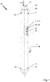
- a coalescence separator 50 is shown in each case.
- the Koaleszenzabscheider 50 of Fig. 4 and 5 is identical, whereby Fig. 4 resulting from an electronic derivative of a color image, whereas Fig. 5 a tracing of the color image is.
- the coalescence separator 50 of the Fig. 4 and 5 technically substantially by its vertical length from the Koaleszenzabscheider 50 after Fig. 1 ,
- a tubular support body 52 This has in its perforated lateral surface 55 via outlet openings (see reference numeral 56 in Fig. 2 ).
- a filter element 1 is mounted, which sits substantially loosely on the support body 52.
- the filter element 1 is in turn surrounded by a protective sock 64.
- the tubular support body 52 extends from a first end 53 to a second end 54. Over the same length, the filter element 1 and the protective sock 64 extend on the support body 52.
- the formed as a filter sock 3 filter layer system 2 of the filter element 1 is with its open ends 4, 5 each in the region of the first and second end 53, 54 of the support body 52 fluid-tight relative to the tubular support body 52 sealed.
- the first end 53 of the support body 52 is closed with a first end plate 60, in which an inlet 51 is formed, which opens into the interior of the support body 52.
- On a connecting piece of the first end plate 60 sits a sealing ring 63, so that the Koaleszenzabscheider 50 is sealingly connected to this connection piece with a supply line.
- a pre-filter element 62 is also arranged, which is designed as a folding part.
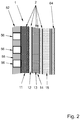
- FIG. 1 A potential for the embodiments according to the Fig. 1 . 4 and 5 usable filter element 1 is closer in connection with Fig. 2 described.
- a longitudinal section through a section of a support body 52, a filter element 1 and a protective sock 64 is shown.
- the filter element 1 consists of a filter layer system 2, which has a first filter layer layer 11 of a nonwoven material and four further filter layer layers 12, 13, 14, 15 of different nonwoven materials. It has the shape of a filter sock, in particular in the form of an elongated, and in particular hollow cylindrical and flaccid hollow body.
- the further filter layer layers 12, 13, 14, 15 are arranged in layers on the first filter layer layer 11 from the inside to the outside.
- the filter layer layers 11, 12, 13, 14, 15 are at least substantially or completely loose on each other. At least one of the filter layer layers 11, 12, 13, 14, 15 is hydrophobic, and at least one of the filter layer layers 11, 12, 13, 14, 15 is hydrophilic.
- the production of the filter elements 1 also takes place phenolharzok.
- the filter layer layers 11, 12, 13, 14, 15 can each be made endless.
- a seamless production of the filter sock 3 is possible, for example by hose-like extrusion of nonwoven material.
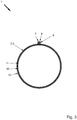
- a cross section through a filter element 1 in which a cross section through a filter element 1 is shown, all the filter layer layers 11, 12, 13, 14, 15 of the filter layer system 2 are connected in the circumferential direction with a common longitudinal seam 6.
- the longitudinal seam 6 is an outwardly facing weld. This is produced in that the filter layer system 2 has two circumferential ends 7, 8, which are welded together facing outwards.
Landscapes
- Chemical & Material Sciences (AREA)
- Chemical Kinetics & Catalysis (AREA)
- Engineering & Computer Science (AREA)
- Oil, Petroleum & Natural Gas (AREA)
- Mechanical Engineering (AREA)
- General Chemical & Material Sciences (AREA)
- Organic Chemistry (AREA)
- Filtering Materials (AREA)
Applications Claiming Priority (1)
| Application Number | Priority Date | Filing Date | Title |
|---|---|---|---|
| DE102018108986.4A DE102018108986A1 (de) | 2018-04-16 | 2018-04-16 | Filterelement, Koaleszenzabscheider und Verfahren zu deren Herstellung sowie deren Verwendung |
Publications (2)
| Publication Number | Publication Date |
|---|---|
| EP3556449A1 true EP3556449A1 (fr) | 2019-10-23 |
| EP3556449B1 EP3556449B1 (fr) | 2021-03-17 |
Family
ID=66217728
Family Applications (1)
| Application Number | Title | Priority Date | Filing Date |
|---|---|---|---|
| EP19169400.9A Active EP3556449B1 (fr) | 2018-04-16 | 2019-04-16 | Élément filtrant, séparateur à coalescence et son procédé de fabrication ainsi que son utilisation |
Country Status (2)
| Country | Link |
|---|---|
| EP (1) | EP3556449B1 (fr) |
| DE (1) | DE102018108986A1 (fr) |
Families Citing this family (1)
| Publication number | Priority date | Publication date | Assignee | Title |
|---|---|---|---|---|
| EP3984616B1 (fr) * | 2020-10-13 | 2025-09-17 | FAUDI Aviation GmbH | Dispositif de filtre et dispositif de séparation |
Citations (7)
| Publication number | Priority date | Publication date | Assignee | Title |
|---|---|---|---|---|
| DE1113783B (de) * | 1957-08-08 | 1961-09-14 | Bendix Corp | Koaleszer zum Trennen von Wasser und fluessigen Kohlenwasserstoffen |
| US4058463A (en) * | 1974-09-03 | 1977-11-15 | Keene Corporation | Element for filtering and separating fluid mixtures |
| EP0308098A1 (fr) * | 1987-08-31 | 1989-03-22 | Minnesota Mining And Manufacturing Company | Sac filtrant flexible et méthode de fabrication |
| US5015376A (en) * | 1990-01-22 | 1991-05-14 | Picek Charles R | Semi-rigid enhanced area filter element |
| US5755962A (en) * | 1996-11-26 | 1998-05-26 | Isp Investments Inc. | Filter bag and process of manufacture |
| US5938921A (en) * | 1997-07-30 | 1999-08-17 | Stanadyne Automotive Corp. | Water baffle for filter cartridge |
| US20140311963A1 (en) * | 2013-03-12 | 2014-10-23 | Schroeder Industries, Llc | Coalescing filter element and filter assembly therefore |
Family Cites Families (4)
| Publication number | Priority date | Publication date | Assignee | Title |
|---|---|---|---|---|
| DE2126080C3 (de) | 1971-05-26 | 1980-08-07 | Faudi-Feinbau Gmbh, 6370 Oberursel | Rohrförmiges Trennelement zum Filtern und Abscheiden von Wasser und Feststoffen aus Kraftstoff |
| DE3818595A1 (de) | 1988-06-01 | 1989-12-07 | Faudi Feinbau | Filterelement fuer filter/wasserabscheider |
| DE102011120653B4 (de) * | 2011-12-09 | 2024-08-01 | Mann+Hummel Gmbh | Kraftstofffilter einer Brennkraftmaschine und Filterelement eines Kraftstofffilters |
| DE102014000903B4 (de) * | 2014-01-21 | 2021-08-12 | Hydac Filtertechnik Gmbh | Filterelement und Filtervorrichtung |
-
2018
- 2018-04-16 DE DE102018108986.4A patent/DE102018108986A1/de not_active Ceased
-
2019
- 2019-04-16 EP EP19169400.9A patent/EP3556449B1/fr active Active
Patent Citations (7)
| Publication number | Priority date | Publication date | Assignee | Title |
|---|---|---|---|---|
| DE1113783B (de) * | 1957-08-08 | 1961-09-14 | Bendix Corp | Koaleszer zum Trennen von Wasser und fluessigen Kohlenwasserstoffen |
| US4058463A (en) * | 1974-09-03 | 1977-11-15 | Keene Corporation | Element for filtering and separating fluid mixtures |
| EP0308098A1 (fr) * | 1987-08-31 | 1989-03-22 | Minnesota Mining And Manufacturing Company | Sac filtrant flexible et méthode de fabrication |
| US5015376A (en) * | 1990-01-22 | 1991-05-14 | Picek Charles R | Semi-rigid enhanced area filter element |
| US5755962A (en) * | 1996-11-26 | 1998-05-26 | Isp Investments Inc. | Filter bag and process of manufacture |
| US5938921A (en) * | 1997-07-30 | 1999-08-17 | Stanadyne Automotive Corp. | Water baffle for filter cartridge |
| US20140311963A1 (en) * | 2013-03-12 | 2014-10-23 | Schroeder Industries, Llc | Coalescing filter element and filter assembly therefore |
Also Published As
| Publication number | Publication date |
|---|---|
| DE102018108986A1 (de) | 2019-10-17 |
| EP3556449B1 (fr) | 2021-03-17 |
Similar Documents
| Publication | Publication Date | Title |
|---|---|---|
| DE3729955C3 (de) | Filterelement sowie Verfahren zu seiner Herstellung | |
| DE69815345T2 (de) | Rückspülluftfilteranordnung | |
| DE2457289C3 (de) | Trennanordnung für ein öl-Wasser-Gemisch | |
| DE69334045T2 (de) | Faltenfilter | |
| EP2044874B1 (fr) | Sac filtrant pour aspirateur | |
| DE60200569T2 (de) | Gefaltetes Filterelement und Verfahren zu seiner Herstellung | |
| DE60222287T2 (de) | Filterpatrone mit strukturell und mit klebstoff befestigter umhüllung und verfahren zu dessen zusammenbau | |
| DE2005051A1 (de) | Röhrenförmiges Filter für die Filterung von Flüssigkeiten | |
| DE102008012521A1 (de) | Filtervorrichtung sowie Filterelement für eine dahingehende Filtervorrichtung | |
| DE102016013166A1 (de) | Filterelement | |
| EP2315624B1 (fr) | Système de filtration à raccords fluidiques | |
| WO2009106593A1 (fr) | Filtre à air doté d'un élément de sécurité | |
| DE102014000903A1 (de) | Filter- und Koaleszenzelement sowie zugehörige Medienlage und Filtervorrichtung | |
| EP2665539A1 (fr) | Elément de filtration comportant au moins une bande de filtration en mats ou en couches | |
| DE3337517C2 (de) | Filterelement und Verfahren zu seiner Herstellung | |
| DE2900081C2 (de) | Filter für ein fliessendes Medium | |
| WO2015018779A1 (fr) | Crible séparateur d'eau pour un élément filtrant dans un filtre de liquide | |
| DE1645749B2 (de) | Vorrichtung zur Abscheidung von Wasser und Ausfilterung von Verunreinigungen aus flüssigen Kohlenwasserstoffen | |
| EP3556449B1 (fr) | Élément filtrant, séparateur à coalescence et son procédé de fabrication ainsi que son utilisation | |
| DE102016008007B4 (de) | Abscheideelement eines Flüssigkeitsabscheiders, Flüssigkeitsabscheider und Verfahren zur Herstellung eines Abscheideelements | |
| DE3332324A1 (de) | Abscheide-filterelement, verfahren zur herstellung eines solchen filterelementes und filtereinrichtung unter verwendung eines solchen filterelementes | |
| DE9318673U1 (de) | Hohlzylindrisches Filterelement und damit hergestellte Filtereinheit | |
| DE102016102309A1 (de) | Abscheidemediumkörper zur Verwendung in einem Abscheider | |
| DE102017119926A1 (de) | Koaleszerstufe eines Filtereinsatzes eines Kraftstofffilters, Filtereinsatz und Kraftstofffilter | |
| EP1698387B1 (fr) | Dispositif de filtration avec poche filtrante |
Legal Events
| Date | Code | Title | Description |
|---|---|---|---|
| PUAI | Public reference made under article 153(3) epc to a published international application that has entered the european phase |
Free format text: ORIGINAL CODE: 0009012 |
|
| STAA | Information on the status of an ep patent application or granted ep patent |
Free format text: STATUS: THE APPLICATION HAS BEEN PUBLISHED |
|
| AK | Designated contracting states |
Kind code of ref document: A1 Designated state(s): AL AT BE BG CH CY CZ DE DK EE ES FI FR GB GR HR HU IE IS IT LI LT LU LV MC MK MT NL NO PL PT RO RS SE SI SK SM TR |
|
| AX | Request for extension of the european patent |
Extension state: BA ME |
|
| STAA | Information on the status of an ep patent application or granted ep patent |
Free format text: STATUS: REQUEST FOR EXAMINATION WAS MADE |
|
| 17P | Request for examination filed |
Effective date: 20200422 |
|
| RBV | Designated contracting states (corrected) |
Designated state(s): AL AT BE BG CH CY CZ DE DK EE ES FI FR GB GR HR HU IE IS IT LI LT LU LV MC MK MT NL NO PL PT RO RS SE SI SK SM TR |
|
| GRAP | Despatch of communication of intention to grant a patent |
Free format text: ORIGINAL CODE: EPIDOSNIGR1 |
|
| STAA | Information on the status of an ep patent application or granted ep patent |
Free format text: STATUS: GRANT OF PATENT IS INTENDED |
|
| INTG | Intention to grant announced |
Effective date: 20201008 |
|
| GRAS | Grant fee paid |
Free format text: ORIGINAL CODE: EPIDOSNIGR3 |
|
| GRAA | (expected) grant |
Free format text: ORIGINAL CODE: 0009210 |
|
| STAA | Information on the status of an ep patent application or granted ep patent |
Free format text: STATUS: THE PATENT HAS BEEN GRANTED |
|
| AK | Designated contracting states |
Kind code of ref document: B1 Designated state(s): AL AT BE BG CH CY CZ DE DK EE ES FI FR GB GR HR HU IE IS IT LI LT LU LV MC MK MT NL NO PL PT RO RS SE SI SK SM TR |
|
| REG | Reference to a national code |
Ref country code: GB Ref legal event code: FG4D Free format text: NOT ENGLISH |
|
| REG | Reference to a national code |
Ref country code: CH Ref legal event code: EP |
|
| REG | Reference to a national code |
Ref country code: DE Ref legal event code: R096 Ref document number: 502019000992 Country of ref document: DE |
|
| REG | Reference to a national code |
Ref country code: IE Ref legal event code: FG4D Free format text: LANGUAGE OF EP DOCUMENT: GERMAN |
|
| REG | Reference to a national code |
Ref country code: AT Ref legal event code: REF Ref document number: 1371713 Country of ref document: AT Kind code of ref document: T Effective date: 20210415 |
|
| REG | Reference to a national code |
Ref country code: LT Ref legal event code: MG9D |
|
| PG25 | Lapsed in a contracting state [announced via postgrant information from national office to epo] |
Ref country code: BG Free format text: LAPSE BECAUSE OF FAILURE TO SUBMIT A TRANSLATION OF THE DESCRIPTION OR TO PAY THE FEE WITHIN THE PRESCRIBED TIME-LIMIT Effective date: 20210617 Ref country code: HR Free format text: LAPSE BECAUSE OF FAILURE TO SUBMIT A TRANSLATION OF THE DESCRIPTION OR TO PAY THE FEE WITHIN THE PRESCRIBED TIME-LIMIT Effective date: 20210317 Ref country code: GR Free format text: LAPSE BECAUSE OF FAILURE TO SUBMIT A TRANSLATION OF THE DESCRIPTION OR TO PAY THE FEE WITHIN THE PRESCRIBED TIME-LIMIT Effective date: 20210618 Ref country code: FI Free format text: LAPSE BECAUSE OF FAILURE TO SUBMIT A TRANSLATION OF THE DESCRIPTION OR TO PAY THE FEE WITHIN THE PRESCRIBED TIME-LIMIT Effective date: 20210317 Ref country code: NO Free format text: LAPSE BECAUSE OF FAILURE TO SUBMIT A TRANSLATION OF THE DESCRIPTION OR TO PAY THE FEE WITHIN THE PRESCRIBED TIME-LIMIT Effective date: 20210617 |
|
| REG | Reference to a national code |
Ref country code: NL Ref legal event code: MP Effective date: 20210317 |
|
| PG25 | Lapsed in a contracting state [announced via postgrant information from national office to epo] |
Ref country code: LV Free format text: LAPSE BECAUSE OF FAILURE TO SUBMIT A TRANSLATION OF THE DESCRIPTION OR TO PAY THE FEE WITHIN THE PRESCRIBED TIME-LIMIT Effective date: 20210317 Ref country code: RS Free format text: LAPSE BECAUSE OF FAILURE TO SUBMIT A TRANSLATION OF THE DESCRIPTION OR TO PAY THE FEE WITHIN THE PRESCRIBED TIME-LIMIT Effective date: 20210317 Ref country code: SE Free format text: LAPSE BECAUSE OF FAILURE TO SUBMIT A TRANSLATION OF THE DESCRIPTION OR TO PAY THE FEE WITHIN THE PRESCRIBED TIME-LIMIT Effective date: 20210317 |
|
| PG25 | Lapsed in a contracting state [announced via postgrant information from national office to epo] |
Ref country code: NL Free format text: LAPSE BECAUSE OF FAILURE TO SUBMIT A TRANSLATION OF THE DESCRIPTION OR TO PAY THE FEE WITHIN THE PRESCRIBED TIME-LIMIT Effective date: 20210317 |
|
| PG25 | Lapsed in a contracting state [announced via postgrant information from national office to epo] |
Ref country code: CZ Free format text: LAPSE BECAUSE OF FAILURE TO SUBMIT A TRANSLATION OF THE DESCRIPTION OR TO PAY THE FEE WITHIN THE PRESCRIBED TIME-LIMIT Effective date: 20210317 Ref country code: EE Free format text: LAPSE BECAUSE OF FAILURE TO SUBMIT A TRANSLATION OF THE DESCRIPTION OR TO PAY THE FEE WITHIN THE PRESCRIBED TIME-LIMIT Effective date: 20210317 Ref country code: LT Free format text: LAPSE BECAUSE OF FAILURE TO SUBMIT A TRANSLATION OF THE DESCRIPTION OR TO PAY THE FEE WITHIN THE PRESCRIBED TIME-LIMIT Effective date: 20210317 Ref country code: SM Free format text: LAPSE BECAUSE OF FAILURE TO SUBMIT A TRANSLATION OF THE DESCRIPTION OR TO PAY THE FEE WITHIN THE PRESCRIBED TIME-LIMIT Effective date: 20210317 |
|
| PG25 | Lapsed in a contracting state [announced via postgrant information from national office to epo] |
Ref country code: PL Free format text: LAPSE BECAUSE OF FAILURE TO SUBMIT A TRANSLATION OF THE DESCRIPTION OR TO PAY THE FEE WITHIN THE PRESCRIBED TIME-LIMIT Effective date: 20210317 Ref country code: SK Free format text: LAPSE BECAUSE OF FAILURE TO SUBMIT A TRANSLATION OF THE DESCRIPTION OR TO PAY THE FEE WITHIN THE PRESCRIBED TIME-LIMIT Effective date: 20210317 Ref country code: PT Free format text: LAPSE BECAUSE OF FAILURE TO SUBMIT A TRANSLATION OF THE DESCRIPTION OR TO PAY THE FEE WITHIN THE PRESCRIBED TIME-LIMIT Effective date: 20210719 Ref country code: RO Free format text: LAPSE BECAUSE OF FAILURE TO SUBMIT A TRANSLATION OF THE DESCRIPTION OR TO PAY THE FEE WITHIN THE PRESCRIBED TIME-LIMIT Effective date: 20210317 Ref country code: IS Free format text: LAPSE BECAUSE OF FAILURE TO SUBMIT A TRANSLATION OF THE DESCRIPTION OR TO PAY THE FEE WITHIN THE PRESCRIBED TIME-LIMIT Effective date: 20210717 |
|
| REG | Reference to a national code |
Ref country code: DE Ref legal event code: R097 Ref document number: 502019000992 Country of ref document: DE |
|
| PG25 | Lapsed in a contracting state [announced via postgrant information from national office to epo] |
Ref country code: LU Free format text: LAPSE BECAUSE OF NON-PAYMENT OF DUE FEES Effective date: 20210416 |
|
| REG | Reference to a national code |
Ref country code: BE Ref legal event code: MM Effective date: 20210430 |
|
| PLBE | No opposition filed within time limit |
Free format text: ORIGINAL CODE: 0009261 |
|
| STAA | Information on the status of an ep patent application or granted ep patent |
Free format text: STATUS: NO OPPOSITION FILED WITHIN TIME LIMIT |
|
| PG25 | Lapsed in a contracting state [announced via postgrant information from national office to epo] |
Ref country code: AL Free format text: LAPSE BECAUSE OF FAILURE TO SUBMIT A TRANSLATION OF THE DESCRIPTION OR TO PAY THE FEE WITHIN THE PRESCRIBED TIME-LIMIT Effective date: 20210317 Ref country code: DK Free format text: LAPSE BECAUSE OF FAILURE TO SUBMIT A TRANSLATION OF THE DESCRIPTION OR TO PAY THE FEE WITHIN THE PRESCRIBED TIME-LIMIT Effective date: 20210317 Ref country code: MC Free format text: LAPSE BECAUSE OF FAILURE TO SUBMIT A TRANSLATION OF THE DESCRIPTION OR TO PAY THE FEE WITHIN THE PRESCRIBED TIME-LIMIT Effective date: 20210317 Ref country code: ES Free format text: LAPSE BECAUSE OF FAILURE TO SUBMIT A TRANSLATION OF THE DESCRIPTION OR TO PAY THE FEE WITHIN THE PRESCRIBED TIME-LIMIT Effective date: 20210317 |
|
| 26N | No opposition filed |
Effective date: 20211220 |
|
| PG25 | Lapsed in a contracting state [announced via postgrant information from national office to epo] |
Ref country code: SI Free format text: LAPSE BECAUSE OF FAILURE TO SUBMIT A TRANSLATION OF THE DESCRIPTION OR TO PAY THE FEE WITHIN THE PRESCRIBED TIME-LIMIT Effective date: 20210317 |
|
| PG25 | Lapsed in a contracting state [announced via postgrant information from national office to epo] |
Ref country code: IT Free format text: LAPSE BECAUSE OF FAILURE TO SUBMIT A TRANSLATION OF THE DESCRIPTION OR TO PAY THE FEE WITHIN THE PRESCRIBED TIME-LIMIT Effective date: 20210317 Ref country code: IE Free format text: LAPSE BECAUSE OF NON-PAYMENT OF DUE FEES Effective date: 20210416 |
|
| PG25 | Lapsed in a contracting state [announced via postgrant information from national office to epo] |
Ref country code: IS Free format text: LAPSE BECAUSE OF FAILURE TO SUBMIT A TRANSLATION OF THE DESCRIPTION OR TO PAY THE FEE WITHIN THE PRESCRIBED TIME-LIMIT Effective date: 20210717 |
|
| PG25 | Lapsed in a contracting state [announced via postgrant information from national office to epo] |
Ref country code: BE Free format text: LAPSE BECAUSE OF NON-PAYMENT OF DUE FEES Effective date: 20210430 |
|
| REG | Reference to a national code |
Ref country code: CH Ref legal event code: PL |
|
| PG25 | Lapsed in a contracting state [announced via postgrant information from national office to epo] |
Ref country code: LI Free format text: LAPSE BECAUSE OF NON-PAYMENT OF DUE FEES Effective date: 20220430 Ref country code: CH Free format text: LAPSE BECAUSE OF NON-PAYMENT OF DUE FEES Effective date: 20220430 |
|
| PG25 | Lapsed in a contracting state [announced via postgrant information from national office to epo] |
Ref country code: CY Free format text: LAPSE BECAUSE OF FAILURE TO SUBMIT A TRANSLATION OF THE DESCRIPTION OR TO PAY THE FEE WITHIN THE PRESCRIBED TIME-LIMIT Effective date: 20210317 |
|
| PG25 | Lapsed in a contracting state [announced via postgrant information from national office to epo] |
Ref country code: HU Free format text: LAPSE BECAUSE OF FAILURE TO SUBMIT A TRANSLATION OF THE DESCRIPTION OR TO PAY THE FEE WITHIN THE PRESCRIBED TIME-LIMIT; INVALID AB INITIO Effective date: 20190416 |
|
| PG25 | Lapsed in a contracting state [announced via postgrant information from national office to epo] |
Ref country code: MK Free format text: LAPSE BECAUSE OF FAILURE TO SUBMIT A TRANSLATION OF THE DESCRIPTION OR TO PAY THE FEE WITHIN THE PRESCRIBED TIME-LIMIT Effective date: 20210317 |
|
| PG25 | Lapsed in a contracting state [announced via postgrant information from national office to epo] |
Ref country code: MT Free format text: LAPSE BECAUSE OF FAILURE TO SUBMIT A TRANSLATION OF THE DESCRIPTION OR TO PAY THE FEE WITHIN THE PRESCRIBED TIME-LIMIT Effective date: 20210317 |
|
| REG | Reference to a national code |
Ref country code: AT Ref legal event code: MM01 Ref document number: 1371713 Country of ref document: AT Kind code of ref document: T Effective date: 20240416 |
|
| PGFP | Annual fee paid to national office [announced via postgrant information from national office to epo] |
Ref country code: DE Payment date: 20250430 Year of fee payment: 7 |
|
| PGFP | Annual fee paid to national office [announced via postgrant information from national office to epo] |
Ref country code: GB Payment date: 20250429 Year of fee payment: 7 |
|
| PGFP | Annual fee paid to national office [announced via postgrant information from national office to epo] |
Ref country code: FR Payment date: 20250429 Year of fee payment: 7 |
|
| PG25 | Lapsed in a contracting state [announced via postgrant information from national office to epo] |
Ref country code: AT Free format text: LAPSE BECAUSE OF NON-PAYMENT OF DUE FEES Effective date: 20240416 |
|
| PG25 | Lapsed in a contracting state [announced via postgrant information from national office to epo] |
Ref country code: TR Free format text: LAPSE BECAUSE OF FAILURE TO SUBMIT A TRANSLATION OF THE DESCRIPTION OR TO PAY THE FEE WITHIN THE PRESCRIBED TIME-LIMIT Effective date: 20210317 |
|
| PGFP | Annual fee paid to national office [announced via postgrant information from national office to epo] |
Ref country code: AT Payment date: 20260410 Year of fee payment: 5 |