EP3556517A1 - Dispositif de rangement d'outil multicouche - Google Patents
Dispositif de rangement d'outil multicouche Download PDFInfo
- Publication number
- EP3556517A1 EP3556517A1 EP18167722.0A EP18167722A EP3556517A1 EP 3556517 A1 EP3556517 A1 EP 3556517A1 EP 18167722 A EP18167722 A EP 18167722A EP 3556517 A1 EP3556517 A1 EP 3556517A1
- Authority
- EP
- European Patent Office
- Prior art keywords
- tube
- block
- shelf
- position hole
- disposed
- Prior art date
- Legal status (The legal status is an assumption and is not a legal conclusion. Google has not performed a legal analysis and makes no representation as to the accuracy of the status listed.)
- Withdrawn
Links
Images




Classifications
-
- B—PERFORMING OPERATIONS; TRANSPORTING
- B25—HAND TOOLS; PORTABLE POWER-DRIVEN TOOLS; MANIPULATORS
- B25H—WORKSHOP EQUIPMENT, e.g. FOR MARKING-OUT WORK; STORAGE MEANS FOR WORKSHOPS
- B25H3/00—Storage means or arrangements for workshops facilitating access to, or handling of, work tools or instruments
- B25H3/02—Boxes
- B25H3/021—Boxes comprising a number of connected storage elements
- B25H3/023—Boxes comprising a number of connected storage elements movable relative to one another for access to their interiors
- B25H3/026—Boxes comprising a number of connected storage elements movable relative to one another for access to their interiors by displacement in a direction substantially perpendicated to th base
Definitions
- the present invention relates to a tool storage device and, in particular, to a multi-layer tool storage device.
- China Utility Model Patent No. CN206393596U discloses a storage device with fold up and lock function, including at least one slide bar, a tool rack, and a locking mechanism.
- the slide bar is provided with a first recess and a second recess.
- the tool rack is connected in this slide bar.
- the tool rack is provided with a first space along a plumb direction and at least one second space along a horizontal direction.
- the locking mechanism is mounted to the tool rack and is movable between a lock position and a release position.
- the locking mechanism includes a first sliding member disposed in the first space, and at least one second sliding member disposed in the second space.
- the second sliding member is inserted into the first recess or the second recess when the locking mechanism is in the lock position.
- the second sliding member is detached from the first recess or the second recess when the locking mechanism is in the release position.
- the storage device with the above structure when folded, it must be pushed down one-layer by one-layer, and then the slide bar is folded back to form a final folded state.
- the above structure is relatively complex and requires many actions in operation. Thus, the storage device cannot be quickly folded or unfolded.
- a tool storage device includes a first shelf and a second shelf.
- the first shelf includes a first tube and a first slide seat mounted at an end of the first tube.
- the first slide seat has first and second slots in communication with each other, a first block slidably mounted in the first slot, a first slider slidably mounted in the second slot, a first abut portion disposed between two opposite ends of the first block, and a second abut portion disposed at an end of the first slider adjacent to the first block and abutted the first abut portion.
- the second shelf includes a second tube.
- the second tube has a first position hole disposed at a side wall thereof. The end of the first tube is movably inserted into the second shelf.
- the first shelf is switchable between a lock state and an unlock state and is movable relative to the second shelf between an unfolded position and a folded position.
- the first block is aligned to the first position hole.
- the first block is inserted into the first position hole.
- the first slider is moved toward the first block and abuts the first block to cause the first block detached from the first position hole to permit the first shelf movable relative to the second shelf.
- the first shelf includes a third tube parallel to the first tube, and a second slide seat mounted at an end of the third tube.
- the second slide seat has third and fourth slots in communication with each other, a second block slidably mounted in the third slot, a second slider slidably mounted in the fourth slot, a third abut portion disposed between two opposite ends of the second block, and a fourth abut portion disposed at an end of the second slider adjacent to the second block and abutted the third abut portion.
- the second shelf includes a fourth tube parallel to the third tube.
- the fourth tube has a second position hole disposed at a side wall thereof. The end of the third tube is movably inserted into the fourth tube.
- the second block When the first shelf is in the unfolded position, the second block is aligned to the second position hole. When the first shelf is in the unfolded position and is switched to the lock state, the second block is inserted into the second position hole. When the first shelf is switched to the unlock state, the second slider is moved toward the second block and abuts the second block to cause the second block detached from the second position hole.
- the first shelf includes a first handle fixed to an end of the first tube opposite to the first slide seat and an end of the third tube opposite to the second slide seat.
- the first tube includes a first push rod movably mounted therein and abutted the first slider.
- the third tube includes second push rod movably mounted therein and abutted the second slider.
- the first handle has a button movably mounted thereon and abutted an end of the first push rod opposite to the first slider and an end of the second push rod opposite to the second slider.
- the first handle has a cover mounted on an outer periphery of the button.
- first and second abut portions are bevel faces not parallel and not perpendicular to extend directions of the first and second slots
- third and fourth abut portions are bevel faces not parallel and not perpendicular to extend directions of the third and fourth slots.
- a first elastic member is disposed in the first slot and abuts between the first slot and the first block
- a second elastic member is disposed in the third slot and abuts between the third slot and the second block.
- the second tube has a third position hole disposed at the side wall thereof and spaced from the first position hole
- the fourth tube has a fourth position hole disposed at the side wall thereof and spaced from the second position hole.
- the second shelf includes a third slide seat mounted at an end of the second tube opposite to the first tube and a fourth slide seat mounted at an end of the fourth tube opposite to the third tube.
- the third slide seat has fifth and sixth slots in communication with each other, a third block slidably mounted in the fifth slot, a third slider slidably mounted in the sixth slot, a fifth abut portion disposed between two opposite ends of the third block, and a sixth abut portion disposed at an end of the third slider adjacent to the third block and abutted the fifth abut portion.
- the fourth slide seat has seventh and eighth slots in communication with each other, a fourth block slidably mounted in the seventh slot, a fourth slider slidably mounted in the eighth slot, a seventh abut portion disposed between two opposite ends of the fourth block, and an eighth abut portion disposed at an end of the fourth slider adjacent to the fourth block and abutted the seventh abut portion.
- the tool storage device further includes a third shelf including a fifth tube and a sixth tube parallel to each other.
- the fifth tube has a fifth position hole disposed at a side wall thereof.
- the end of the second tube opposite to the first tube is movably inserted into the fifth tube.
- the sixth tube has a sixth position hole disposed at a side wall thereof.
- the end of the fourth tube opposite to the third tube is movably inserted into the sixth tube.
- the second shelf is switchable between a lock state and an unlock state and is movable relative to the third shelf between an unfolded position and a folded position.
- the third block is aligned to the fifth position hole
- the fourth block is aligned to the sixth position hole.
- the third block is inserted into the fifth position hole
- the fourth block is inserted into the sixth position hole.
- the third slider is moved toward the third block and abuts the third block to cause the third block detached from the fifth position hole
- the fourth slider is moved toward the fourth block and abuts the fourth block to cause the fourth block detached from the sixth position hole.
- the fifth tube has a first lock hole disposed at the side wall thereof.
- the sixth tube has a second lock hole disposed at the side wall thereof.
- the first slide seat abuts the third slider, and the second slide seat abuts the fourth slider to cause the second shelf switched to the unlock state and moved to the folded position.
- the fifth and sixth abut portions are bevel faces not parallel and not perpendicular to extend directions of the fifth and sixth slots
- the seventh and eighth abut portions are bevel faces not parallel and not perpendicular to extend directions of the seventh and eighth slots.
- a third elastic member is disposed in the fifth slot and abuts between the fifth slot and the third block
- a fourth elastic member is disposed in the seventh slot and abuts between the seventh slot and the fourth block.
- the first shelf includes a first platform fixed between the first and third tubes
- the second shelf includes a second platform fixed between the second and fourth tubes
- the third shelf includes a third platform fixed between the fifth and sixth tubes.
- the first shelf includes a seventh tube, an eighth tube, and a second handle fixed to the seventh and eighth tubes.
- the seventh tube has a structure the same as that of the first tube
- the eighth tube has a structure the same as that of the third tube
- the second handle has a structure the same as that of the first handle.
- the first platform is fixed to the seventh and eighth tubes.
- the first and seventh tubes are arranged at two opposite corners of the first platform, and the third and eighth tubes are arranged at two opposite corners of the first platform.
- the second shelf includes a ninth tube and a tenth tube.
- the ninth tube has a structure the same as that of the second tube
- the tenth tube has a structure the same as that of the fourth tube.
- the second platform is fixed to the ninth and tenth tubes.
- the ninth and tenth tubes are arranged at an end of the second platform opposite to the second and fourth tubes.
- the third shelf includes an eleventh tube and a twelfth tube.
- the eleventh tube has a structure the same as that of the fifth tube
- the twelfth tube has a structure the same as that of the sixth tube.
- the third platform is fixed to the eleventh and twelfth tubes.
- the eleventh and twelfth tubes are arranged at an end of the third platform opposite to the fifth and sixth tubes.
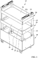
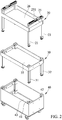
- FIGS. 1-11 show a tool storage device 10 according to the present invention.
- the tool storage device 10 includes a first shelf 20, a second shelf 30, and a third shelf 40.
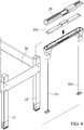
- the first shelf 20 includes a first tube 21 and a first slide seat 22 mounted at an end of the first tube 21.
- the first slide seat 22 has first and second slots 221 and 222 in communication with each other, a first block 223 slidably mounted in the first slot 221, a first slider 224 slidably mounted in the second slot 222, a first abut portion 225 disposed between two opposite ends of the first block 223, and a second abut portion 226 disposed at an end of the first slider 224 adjacent to the first block 223 and abutted the first abut portion 225.
- the first and second abut portions 225 and 226 are bevel faces not parallel and not perpendicular to extend directions of the first and second slots 221 and 222.
- a first elastic member 227 is disposed in the first slot 221 and abuts between the first slot 221 and the first block 223.
- the second shelf 30 includes a second tube 31.
- the second tube 31 has a first position hole 311 disposed at a side wall thereof. The end of the first tube 21 is movably inserted into the second shelf 30.
- the first shelf 20 includes a third tube 23 parallel to the first tube 21, and a second slide seat 24 mounted at an end of the third tube 23.
- the second slide seat 24 has third and fourth slots 241 and 242 in communication with each other, a second block 243 slidably mounted in the third slot 241, a second slider 244 slidably mounted in the fourth slot 242, a third abut portion 245 disposed between two opposite ends of the second block 243, and a fourth abut portion 246 disposed at an end of the second slider 244 adjacent to the second block 243 and abutted the third abut portion 245.
- the third and fourth abut portions 245 and 246 are bevel faces not parallel and not perpendicular to extend directions of the third and fourth slots 241 and 242.
- a second elastic member 247 is disposed in the third slot 241 and abuts between the third slot 241 and the second block 243.
- the second shelf 30 includes a fourth tube 32 parallel to the third tube 23.
- the fourth tube 32 has a second position hole 321 disposed at a side wall thereof. The end of the third tube 23 is movably inserted into the fourth tube 32.
- the second tube 31 has a third position hole 312 disposed at the side wall thereof and spaced from the first position hole 311.
- the fourth tube 32 has a fourth position hole 322 disposed at the side wall thereof and spaced from the second position hole 321.
- the first shelf 20 includes a first handle 25 and a first platform 26.
- the first handle 25 is fixed to an end of the first tube 21 opposite to the first slide seat 22 and an end of the third tube 23 opposite to the second slide seat 24.
- the first platform 26 is fixed between the first and third tubes 21 and 23.
- the first tube 21 includes a first push rod 211 movably mounted therein and abutted the first slider 224.
- the third tube 23 includes second push rod 231 movably mounted therein and abutted the second slider 244.
- the first handle 25 has a button 251 movably mounted thereon and abutted an end of the first push rod 211 opposite to the first slider 224 and an end of the second push rod 231 opposite to the second slider 244.
- the first shelf 20 is switchable between a lock state and an unlock state and is movable relative to the second shelf 30 between an unfolded position and a folded position.
- the first block 223 is aligned to the first position hole 311, and the second block 243 is aligned to the second position hole 321.
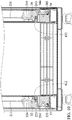
- the first elastic member 227 is located at a side of the first block 223 opposite to the first position hole 311 and pushes the first block 223 to cause the first block 223 inserted into the first position hole 311, and the second elastic member 247 is located at a side of the second block 243 opposite to the second position hole 321 and pushes the second block 243 to cause the second block 243 inserted into the second position hole 321. Therefore, the first shelf 20 cannot be movable relative to the second shelf 30 in the lock state of the first shelf 20.
- the first slider 224 is moved toward the first block 223 and abuts the first block 223 to cause the first block 223 detached from the first position hole 311, and the second slider 244 is moved toward the second block 243 and abuts the second block 243 to cause the second block 243 detached from the second position hole 321, to permit the first shelf 20 movable relative to the second shelf 30 ( FIG. 7 ).
- the first block 223 is aligned to the third position hole 312, and the second block 243 is aligned to the fourth position hole 322 ( FIG. 8 ).
- the second shelf 30 includes a third slide seat 33 mounted at an end of the second tube 31 opposite to the first tube 21 and a fourth slide seat 34 mounted at an end of the fourth tube 32 opposite to the third tube 23.
- the third slide seat 33 has fifth and sixth slots 331 and 332 in communication with each other, a third block 333 slidably mounted in the fifth slot 331, a third slider 334 slidably mounted in the sixth slot 332, a fifth abut portion 335 disposed between two opposite ends of the third block 333, and a sixth abut portion 336 disposed at an end of the third slider 334 adjacent to the third block 333 and abutted the fifth abut portion 335.
- the fifth and sixth abut portions 335 and 336 are bevel faces not parallel and not perpendicular to extend directions of the fifth and sixth slots 331 and 332.
- a third elastic member 337 is disposed in the fifth slot 331 and abuts between the fifth slot 331 and the third block 333.
- the fourth slide seat 34 has seventh and eighth slots 341, 342 in communication with each other, a fourth block 343 slidably mounted in the seventh slot 341, a fourth slider 344 slidably mounted in the eighth slot 342, a seventh abut portion 345 disposed between two opposite ends of the fourth block 343, and an eighth abut portion 346 disposed at an end of the fourth slider 344 adjacent to the fourth block 343 and abutted the seventh abut portion 345.
- the seventh and eighth abut portions 345 and 346 are bevel faces not parallel and not perpendicular to extend directions of the seventh and eighth slots 341 and 342.
- a fourth elastic member 347 is disposed in the seventh slot 341 and abuts between the seventh slot 341 and the fourth block 343.
- the second shelf 30 includes a second platform 35 fixed between the second and fourth tubes 31 and 32.
- the third shelf 40 includes a fifth tube 41 and a sixth tube 42 parallel to each other.
- the fifth tube 41 has a fifth position hole 411 disposed at a side wall thereof.
- the end of the second tube 31 opposite to the first tube 21 is movably inserted into the fifth tube 41.
- the sixth tube 42 has a sixth position hole 421 disposed at a side wall thereof.
- the end of the fourth tube 32 opposite to the third tube 23 is movably inserted into the sixth tube 42.
- the fifth tube 41 has a first lock hole 412 disposed at the side wall thereof.
- the sixth tube 42 has a second lock hole 422 disposed at the side wall thereof.
- the third shelf 40 includes a third platform 43 fixed between the fifth and sixth tubes 41 and 42.
- the second shelf 30 is switchable between a lock state and an unlock state and is movable relative to the third shelf 40 between an unfolded position and a folded position.
- the third block 333 is aligned to the fifth position hole 411
- the fourth block 343 is aligned to the sixth position hole 421.
- the third elastic member 337 is located at a side of the third block 333 opposite to the fifth position hole 411 and pushes the third block 333 to cause the third block 333 inserted into the fifth position hole 411
- the fourth elastic member 347 is located at a side of the fourth block 343 opposite to the sixth position hole 421 and pushes the fourth block 343 to cause the fourth block 343 inserted into the sixth position hole 421. Therefore, the second shelf 30 cannot be movable relative to the third shelf 40 in the lock state of the second shelf 30.
- the third slider 334 is moved toward the third block 333 and abuts the third block 333 to cause the third block 333 detached from the fifth position hole 411
- the fourth slider 344 is moved toward the fourth block 343 and abuts the fourth block 343 to cause the fourth block 343 detached from the sixth position hole 421. Therefore, the second shelf 30 can be movable relative to the third shelf 40 in the unlock state of the second shelf 30.
- the first slide seat 22 abuts the third slider 334, and the second slide seat 24 abuts the fourth slider 344 to cause the second shelf 30 switched to the unlock state and is moved to the folded position.
- the first block 223 is aligned to the third position hole 312 and the first lock hole 412
- the second block 243 is aligned to the fourth position hole 322 and the second lock hole 422.
- the first handle 25 has a cover 252 mounted on an outer periphery of the button 251 to provide the function of preventing mistakenly touching.
- the first shelf 20 includes a seventh tube 27, an eighth tube 28, and a second handle 29 fixed to the seventh and eighth tubes 27 and 28.
- the seventh tube 27 has a structure the same as that of the first tube 21, the eighth tube 28 has a structure the same as that of the third tube 23, and the second handle 29 has a structure the same as that of the first handle 25.
- the first platform 26 is fixed to the seventh and eighth tubes 27 and 28.
- the first and seventh tubes 21 and 27 are arranged at two opposite corners of the first platform 26, and the third and eighth tubes 23 and 28 are arranged at another two opposite corners of the first platform 26.
- the second shelf 30 includes a ninth tube 36 and a tenth tube 37.
- the ninth tube 36 has a structure the same as that of the second tube 31, and the tenth tube 37 has a structure the same as that of the fourth tube 32.
- the second platform 35 is fixed to the ninth and tenth tubes 36 and 37.
- the ninth and tenth tubes 36 and 37 are arranged at an end of the second platform 35 opposite to the second and fourth tubes 31 and 32.
- the third shelf 40 includes an eleventh tube 44 and a twelfth tube 45.
- the eleventh tube 44 has a structure the same as that of the fifth tube 41, and the twelfth tube 45 has a structure the same as that of the sixth tube 42.
- the third platform 43 is fixed to the eleventh and twelfth tubes 44 and 45.
- the eleventh and twelfth tubes 44 and 45 are arranged at an end of the third platform 43 opposite to the fifth and sixth tubes 41 and 42.
- the tool storage device 10 can provide a very quick and simple folding manner through the above-mentioned structure.
- the first shelf 20 can naturally fall after pressing the button 251, and the first shelf 20 can be gently lowered to move to the folded position, and the second shelf 30 is also drived simultaneously to move to the folded position.
Landscapes
- Engineering & Computer Science (AREA)
- Mechanical Engineering (AREA)
- Handcart (AREA)
Priority Applications (1)
| Application Number | Priority Date | Filing Date | Title |
|---|---|---|---|
| EP18167722.0A EP3556517A1 (fr) | 2018-04-17 | 2018-04-17 | Dispositif de rangement d'outil multicouche |
Applications Claiming Priority (1)
| Application Number | Priority Date | Filing Date | Title |
|---|---|---|---|
| EP18167722.0A EP3556517A1 (fr) | 2018-04-17 | 2018-04-17 | Dispositif de rangement d'outil multicouche |
Publications (1)
| Publication Number | Publication Date |
|---|---|
| EP3556517A1 true EP3556517A1 (fr) | 2019-10-23 |
Family
ID=62046661
Family Applications (1)
| Application Number | Title | Priority Date | Filing Date |
|---|---|---|---|
| EP18167722.0A Withdrawn EP3556517A1 (fr) | 2018-04-17 | 2018-04-17 | Dispositif de rangement d'outil multicouche |
Country Status (1)
| Country | Link |
|---|---|
| EP (1) | EP3556517A1 (fr) |
Cited By (6)
| Publication number | Priority date | Publication date | Assignee | Title |
|---|---|---|---|---|
| CN111203845A (zh) * | 2020-03-13 | 2020-05-29 | 成都四方建设工程项目管理有限公司 | 监理造价预算使用的工具箱 |
| CN112077806A (zh) * | 2020-08-31 | 2020-12-15 | 赣州毫厘测绘信息技术有限公司 | 一种工程测量用的便携式测量工具 |
| CN112440263A (zh) * | 2020-11-19 | 2021-03-05 | 深圳供电局有限公司 | 一种oms系统用检修工具箱 |
| CN112894744A (zh) * | 2021-01-27 | 2021-06-04 | 王少瑾 | 一种用于防盗门窗加工工具的带锁工具支架 |
| WO2021137205A1 (fr) * | 2020-01-05 | 2021-07-08 | Keter Plastic Ltd. | Ensemble poignée pliable |
| CN113843762A (zh) * | 2021-10-09 | 2021-12-28 | 杭州金韩压缩机有限公司 | 一种用于涡旋空压机生产的运输装置 |
Citations (4)
| Publication number | Priority date | Publication date | Assignee | Title |
|---|---|---|---|---|
| DE2810401A1 (de) * | 1978-03-10 | 1979-09-13 | Wuerth Adolf Schrauben | Werkzeugwagen, insbesondere fuer reparaturwerkstaetten o.dgl. |
| US6047750A (en) * | 1998-03-17 | 2000-04-11 | Jensen; Steven M. | Modular utility stand storage apparatus and method |
| EP3199306A1 (fr) * | 2016-02-01 | 2017-08-02 | Macc | Dispositif de rangement pour outils |
| CN206393596U (zh) | 2016-11-16 | 2017-08-11 | 张庭瑜 | 具有收折及锁定功能的工具收纳装置 |
-
2018
- 2018-04-17 EP EP18167722.0A patent/EP3556517A1/fr not_active Withdrawn
Patent Citations (4)
| Publication number | Priority date | Publication date | Assignee | Title |
|---|---|---|---|---|
| DE2810401A1 (de) * | 1978-03-10 | 1979-09-13 | Wuerth Adolf Schrauben | Werkzeugwagen, insbesondere fuer reparaturwerkstaetten o.dgl. |
| US6047750A (en) * | 1998-03-17 | 2000-04-11 | Jensen; Steven M. | Modular utility stand storage apparatus and method |
| EP3199306A1 (fr) * | 2016-02-01 | 2017-08-02 | Macc | Dispositif de rangement pour outils |
| CN206393596U (zh) | 2016-11-16 | 2017-08-11 | 张庭瑜 | 具有收折及锁定功能的工具收纳装置 |
Cited By (7)
| Publication number | Priority date | Publication date | Assignee | Title |
|---|---|---|---|---|
| WO2021137205A1 (fr) * | 2020-01-05 | 2021-07-08 | Keter Plastic Ltd. | Ensemble poignée pliable |
| CN111203845A (zh) * | 2020-03-13 | 2020-05-29 | 成都四方建设工程项目管理有限公司 | 监理造价预算使用的工具箱 |
| CN111203845B (zh) * | 2020-03-13 | 2021-01-22 | 成都四方建设工程项目管理有限公司 | 监理造价预算使用的工具箱 |
| CN112077806A (zh) * | 2020-08-31 | 2020-12-15 | 赣州毫厘测绘信息技术有限公司 | 一种工程测量用的便携式测量工具 |
| CN112440263A (zh) * | 2020-11-19 | 2021-03-05 | 深圳供电局有限公司 | 一种oms系统用检修工具箱 |
| CN112894744A (zh) * | 2021-01-27 | 2021-06-04 | 王少瑾 | 一种用于防盗门窗加工工具的带锁工具支架 |
| CN113843762A (zh) * | 2021-10-09 | 2021-12-28 | 杭州金韩压缩机有限公司 | 一种用于涡旋空压机生产的运输装置 |
Similar Documents
| Publication | Publication Date | Title |
|---|---|---|
| EP3556517A1 (fr) | Dispositif de rangement d'outil multicouche | |
| US10220527B1 (en) | Switchblade | |
| AU2024200155B2 (en) | Unlock device and stroller | |
| US6357080B1 (en) | Multi-sections retractable handle | |
| US6339862B1 (en) | Single-handed folding device (II) | |
| EP2927090B1 (fr) | Châssis de poussette pliable | |
| WO2012037153A2 (fr) | Verrou de sûreté pour chaise pliante | |
| US20170297599A1 (en) | Collapsible seat assembly and a stroller with the same | |
| US10058187B2 (en) | Folding step stool | |
| EP3345816A1 (fr) | Véhicule pliable | |
| US9717335B2 (en) | Drawer stop mechanism for sliding drawer | |
| US20230220699A1 (en) | Collapsible canopy | |
| US10017099B2 (en) | Tonneau cover with two sets of folding legs | |
| CN106364544A (zh) | 带有一体化键盘组件的方向盘 | |
| US9609946B2 (en) | Table arrangement | |
| US20170332647A1 (en) | Cake leveler | |
| KR20220058539A (ko) | 접이식 높이 조절 테이블 | |
| US10004350B1 (en) | Knife holder | |
| CN101830289B (zh) | 一种锁紧装置 | |
| GB2511207A (en) | Backrest for a vehicle seat and vehicle seat | |
| EP1997709A2 (fr) | Dispositif pour le verrouillage et le déverrouillage des positions pliée et dépliée d'une poussette | |
| CN206968743U (zh) | 一种可折叠童车车架 | |
| US20230373077A1 (en) | Foldable Workbench | |
| EP1929897B1 (fr) | Poignée pliable pour chariot de supermarché | |
| CN206654086U (zh) | 婴儿推车推把锁定解锁机构 |
Legal Events
| Date | Code | Title | Description |
|---|---|---|---|
| PUAI | Public reference made under article 153(3) epc to a published international application that has entered the european phase |
Free format text: ORIGINAL CODE: 0009012 |
|
| STAA | Information on the status of an ep patent application or granted ep patent |
Free format text: STATUS: THE APPLICATION HAS BEEN PUBLISHED |
|
| AK | Designated contracting states |
Kind code of ref document: A1 Designated state(s): AL AT BE BG CH CY CZ DE DK EE ES FI FR GB GR HR HU IE IS IT LI LT LU LV MC MK MT NL NO PL PT RO RS SE SI SK SM TR |
|
| AX | Request for extension of the european patent |
Extension state: BA ME |
|
| STAA | Information on the status of an ep patent application or granted ep patent |
Free format text: STATUS: THE APPLICATION IS DEEMED TO BE WITHDRAWN |
|
| 18D | Application deemed to be withdrawn |
Effective date: 20200603 |