EP3556593A1 - Véhicule de travail doté du dispositif déflecteur d'air de refroidissement côté sortie - Google Patents
Véhicule de travail doté du dispositif déflecteur d'air de refroidissement côté sortie Download PDFInfo
- Publication number
- EP3556593A1 EP3556593A1 EP18168563.7A EP18168563A EP3556593A1 EP 3556593 A1 EP3556593 A1 EP 3556593A1 EP 18168563 A EP18168563 A EP 18168563A EP 3556593 A1 EP3556593 A1 EP 3556593A1
- Authority
- EP
- European Patent Office
- Prior art keywords
- cooling air
- work vehicle
- engine compartment
- air outlet
- vehicle according
- Prior art date
- Legal status (The legal status is an assumption and is not a legal conclusion. Google has not performed a legal analysis and makes no representation as to the accuracy of the status listed.)
- Granted
Links
Images
Classifications
-
- F—MECHANICAL ENGINEERING; LIGHTING; HEATING; WEAPONS; BLASTING
- F01—MACHINES OR ENGINES IN GENERAL; ENGINE PLANTS IN GENERAL; STEAM ENGINES
- F01P—COOLING OF MACHINES OR ENGINES IN GENERAL; COOLING OF INTERNAL-COMBUSTION ENGINES
- F01P5/00—Pumping cooling-air or liquid coolants
- F01P5/02—Pumping cooling-air; Arrangements of cooling-air pumps, e.g. fans or blowers
- F01P5/06—Guiding or ducting air to, or from, ducted fans
-
- B—PERFORMING OPERATIONS; TRANSPORTING
- B60—VEHICLES IN GENERAL
- B60K—ARRANGEMENT OR MOUNTING OF PROPULSION UNITS OR OF TRANSMISSIONS IN VEHICLES; ARRANGEMENT OR MOUNTING OF PLURAL DIVERSE PRIME-MOVERS IN VEHICLES; AUXILIARY DRIVES FOR VEHICLES; INSTRUMENTATION OR DASHBOARDS FOR VEHICLES; ARRANGEMENTS IN CONNECTION WITH COOLING, AIR INTAKE, GAS EXHAUST OR FUEL SUPPLY OF PROPULSION UNITS IN VEHICLES
- B60K11/00—Arrangement in connection with cooling of propulsion units
- B60K11/06—Arrangement in connection with cooling of propulsion units with air cooling
-
- B—PERFORMING OPERATIONS; TRANSPORTING
- B60—VEHICLES IN GENERAL
- B60K—ARRANGEMENT OR MOUNTING OF PROPULSION UNITS OR OF TRANSMISSIONS IN VEHICLES; ARRANGEMENT OR MOUNTING OF PLURAL DIVERSE PRIME-MOVERS IN VEHICLES; AUXILIARY DRIVES FOR VEHICLES; INSTRUMENTATION OR DASHBOARDS FOR VEHICLES; ARRANGEMENTS IN CONNECTION WITH COOLING, AIR INTAKE, GAS EXHAUST OR FUEL SUPPLY OF PROPULSION UNITS IN VEHICLES
- B60K11/00—Arrangement in connection with cooling of propulsion units
- B60K11/08—Air inlets for cooling; Shutters or blinds therefor
-
- F—MECHANICAL ENGINEERING; LIGHTING; HEATING; WEAPONS; BLASTING
- F01—MACHINES OR ENGINES IN GENERAL; ENGINE PLANTS IN GENERAL; STEAM ENGINES
- F01P—COOLING OF MACHINES OR ENGINES IN GENERAL; COOLING OF INTERNAL-COMBUSTION ENGINES
- F01P11/00—Component parts, details, or accessories not provided for in, or of interest apart from, groups F01P1/00 - F01P9/00
- F01P11/10—Guiding or ducting cooling-air, to, or from, liquid-to-air heat exchangers
-
- F—MECHANICAL ENGINEERING; LIGHTING; HEATING; WEAPONS; BLASTING
- F01—MACHINES OR ENGINES IN GENERAL; ENGINE PLANTS IN GENERAL; STEAM ENGINES
- F01P—COOLING OF MACHINES OR ENGINES IN GENERAL; COOLING OF INTERNAL-COMBUSTION ENGINES
- F01P7/00—Controlling of coolant flow
- F01P7/02—Controlling of coolant flow the coolant being cooling-air
-
- B—PERFORMING OPERATIONS; TRANSPORTING
- B60—VEHICLES IN GENERAL
- B60R—VEHICLES, VEHICLE FITTINGS, OR VEHICLE PARTS, NOT OTHERWISE PROVIDED FOR
- B60R19/00—Wheel guards; Radiator guards, e.g. grilles; Obstruction removers; Fittings damping bouncing force in collisions
- B60R19/52—Radiator or grille guards ; Radiator grilles
-
- B—PERFORMING OPERATIONS; TRANSPORTING
- B60—VEHICLES IN GENERAL
- B60Y—INDEXING SCHEME RELATING TO ASPECTS CROSS-CUTTING VEHICLE TECHNOLOGY
- B60Y2200/00—Type of vehicle
- B60Y2200/10—Road Vehicles
- B60Y2200/14—Trucks; Load vehicles, Busses
- B60Y2200/142—Heavy duty trucks
-
- B—PERFORMING OPERATIONS; TRANSPORTING
- B60—VEHICLES IN GENERAL
- B60Y—INDEXING SCHEME RELATING TO ASPECTS CROSS-CUTTING VEHICLE TECHNOLOGY
- B60Y2200/00—Type of vehicle
- B60Y2200/20—Off-Road Vehicles
-
- B—PERFORMING OPERATIONS; TRANSPORTING
- B60—VEHICLES IN GENERAL
- B60Y—INDEXING SCHEME RELATING TO ASPECTS CROSS-CUTTING VEHICLE TECHNOLOGY
- B60Y2200/00—Type of vehicle
- B60Y2200/40—Special vehicles
- B60Y2200/41—Construction vehicles, e.g. graders, excavators
Definitions
- the invention relates to a work vehicle with an internal combustion engine arranged in an engine compartment and an operating station arranged above the engine compartment.
- cooling air for the engine compartment by means of a cooling air blower is sucked through a radiator.
- the cooling air blower then conveys the cooling air through the engine compartment, with the cooling air leaving the engine compartment at a cooling air outlet.
- cooling air device With such a construction of a cooling air device, sucked cooling air is very strongly heated by the radiator. The already highly heated cooling air then flows into the engine compartment below the operator station or a driver's cab, so that there is a noticeable warming of the operator station or the driver's cab. Furthermore, the engine compartment is also heated. In such cooling air devices, depending on the direction of travel, the effect may occur that strongly heated cooling air discharged from the engine compartment is sucked in again. Thus, insufficient cold air is available for thermal regulation, which can lead to overheating.
- the object underlying the invention is seen to provide a working vehicle in which an improved cooling of the engine compartment is made possible.
- a work vehicle is proposed with an internal combustion engine arranged in an engine compartment, an operator station above the engine compartment, and a cooling air device with a cooling air inlet, a cooling air outlet, a cooling air fan, and a cooler arranged in the flow path of the cooling air through the engine compartment between the cooling air inlet and the cooling air outlet ,
- the cooling air inlet of the engine compartment is provided on a first (side) vehicle side and / or vehicle underside and the cooling air outlet of the engine compartment is provided on a vehicle front side, the cooling air outlet adeluftablenk observed which is designed so that exiting cooling air is guided in the direction of a second (side) vehicle side.
- the cooling air flow exits at an oblique angle to the main traveling direction (in a plan view), so that it is guided to one side of the vehicle.
- exiting cooling air is already deflected during movement of the working vehicle in the main direction in the cooling air outlet so that it is almost completely displaced by the flowing against the cooling air outlet wind to the second (side) side of the vehicle.
- heated cooling air escaping from the engine compartment is not sucked back because the cooling air intake is on the other side of the vehicle (first side of the vehicle) and / or on the underside of the vehicle.
- fresh, cooler ambient air is always sucked in through the cooling air inlet.
- the cooling air blower may be located upstream of the radiator and downstream of the internal combustion engine relative to the cooling air flow.
- air in the engine compartment which has been slightly heated in the engine compartment, is conveyed through the radiator.
- it is prevented that for the purpose of engine compartment cooling inflowing air is first heated in the radiator. Accordingly, a thermal overload can be excluded.
- the radiator may be located upstream of the cooling air outlet and downstream of the cooling air blower with respect to the cooling air flow. This ensures that cooling air which has passed through the radiator can leave the engine compartment via the cooling outlet over a short distance.
- cooling air inlet is arranged upstream of the cooling air blower, wherein the internal combustion engine is arranged in the flow path of the cooling air between the cooling air inlet and the cooling air blower.
- the cooling air deflection device may have a plurality of air baffles arranged in the cooling air outlet, which are arranged inclined with respect to a flow cross-sectional plane through the cooling air outlet.
- the inclined air baffles allow a targeted deflection of exiting cooling air.
- the air baffles in the cooling air outlet can be arranged substantially vertically and parallel to each other.
- the baffles form vertical standing about a vertical axis rotated or inclined flow obstacles, which deflect the cooling air flow to one side.
- the air baffles can form an acute angle with an imaginary straight line lying in the flow cross-sectional plane, which extends substantially horizontally, parallel to a vehicle front axis, which lies on the air baffle side facing away from the first vehicle side.
- the acute angle may be about 25 ° to 60 °, preferably about 35 ° to 50 °. This ensures that the outflowing cooling air is deflected sufficiently to the desired side, without an outflow opening existing between two adjacent air deflectors having too small a flow cross-section which severely impedes the escape of cooling air.
- the internal combustion engine can be installed with its drive axle in the longitudinal direction of the working vehicle. This allows a laterally offset with respect to the longitudinal axis of the vehicle installation.
- the internal combustion engine for example, be arranged closer to the first side of the vehicle, where the cooling air inlet is arranged so that inflowing ambient air, equal to the internal combustion engine flows around.
- the operator station can be accommodated in a cabin.
- the cabin may have a cabin access arranged on the second vehicle side.
- the car access can for example be a hinged door. This ensures that the cooling air inlet on the first side of the vehicle is permanently free. This is also the case when the cooling air inlet is on the underside of the vehicle.
- the work vehicle may be a dump truck with a dump body arranged behind the service station with respect to a main travel direction. This ensures that, especially during long journeys with the dumper, the unclear, material-filled dump body does not restrict the driver's field of vision.
- the operator station can be rotated by 180 °, such that the operator station can be aligned and locked either in the main direction of travel or counter to the main direction of travel.
- the operator station can be aligned according to the needs to be carried out depending on the work or route to be performed.
- the operator station can be rotatable relative to the cabin. That is, the cabin remains firmly connected to the work vehicle or its body, while the operator station can be rotated together with appropriate controls such as steering wheel, foot pedals and other controls.
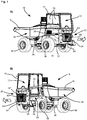
- FIG. 1 is shown in the sub-figures A) and B) schematically and simplified a working vehicle 10 in a respective perspective view.
- the working vehicle 10 is here for example a so-called dumper.
- An operator station 12 of the work vehicle 10 is arranged in a cabin 14 in the present example.
- the cab 14 is optional and the work vehicle 10 may also be implemented with an operator station 12 without a cab 14.
- the operator station 12 is located in front of a dump body 16 of the work vehicle 10 relative to a main direction of travel HR.
- a cooling air inlet 20 is arranged on a first vehicle side 18 ( Fig. 1A ) of the work vehicle 10, which corresponds to the right side in the present example with respect to the main travel direction HR.
- the cooling air inlet 20 is provided on the body or on trim parts 44 of the work vehicle 10 opening behind which a in FIG. 1 invisible engine compartment is located.
- a cooling air outlet 24 is arranged at the vehicle front 22 .
- the cooling air outlet 24 is provided on the body or on trim parts of the work vehicle 10 opening to the invisible engine compartment.
- the car on the first side of the vehicle 18 has two relatively movable sliding window 25.
- an access 28 to the operator station 12 or the cabin 14 is provided on a second vehicle side 26 ( Fig. 1B ) of the work vehicle.
- the access 28 to the operator station 12 comprises a plurality of steps 30 and a car door 32.
- the work vehicle 10 has a front axle 34 and a rear axle 36, two wheels 38 being mounted on each axle.
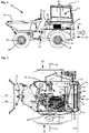
- FIG. 2 shows a simplified and schematic, elevation of the first (right) vehicle side 18. It should be noted that in the FIG. 2 already known reference numerals from the FIG. 1 are shown, even if the relevant elements of the work vehicle will not be described again. From the representation of FIG. 2 It can be seen that the work vehicle 10 between the front axle 34 and the rear axle 36 has an articulated joint arrangement 40 which can be actuated in a known manner in order to be able to change direction when driving with the work vehicle 10. About the front axle 34 is a hood-like body assembly or lining arrangement 42 can be seen, under which the engine compartment is located. In a lateral lining component 44, the cooling air inlet 20 is formed, which is shown in the drawing as a black area.
- FIG. 3 shows a sectional view through the front part of the working vehicle 10 at the level of the section line III-III of FIG. 2 , In this illustration, the view is released on the already mentioned engine compartment 46.
- an internal combustion engine 48 is housed, which may for example be a diesel engine.
- a cooling air blower 50 is connected.
- the cooling-air blower 50 has, in particular, a fan 52, which is coupled to the internal combustion engine by means of a shaft 54, so that the fan 52 is set into rotation when the internal combustion engine is running.
- the cooling air blower 52 is connected to a drive of a cooling water pump device of the internal combustion engine 48.
- the cooling-air blower 50 is designed such that, by means of the fan 52, cooling air KL from the surroundings of the working vehicle 10 through the cooling-air inlet 20 is sucked into the engine compartment 46.
- the sucked-in cooling air KL serves to cool the engine compartment 46 and the internal combustion engine 48.
- the cooling air fan 50 conveys the cooling air KL to the cooling air outlet 24 arranged in the vehicle front 22. In this case, the cooling air KL is pressed or conveyed by means of the cooling air blower 50 through a cooler 56.
- the radiator 56 is disposed upstream of the cooling air outlet 24 and downstream of the cooling air blower 50. Between the radiator 56 and the internal combustion engine 48 dividing walls 57 are arranged, which are funnel-shaped towards the cooling air blower 50. This ensures that cooling air KL conveyed by the cooling-air blower 50 in the direction of the radiator 56 can be reliably conveyed out of the engine compartment 48 through the cooling-air outlet 24 and thus does not re-enter the engine compartment 46.
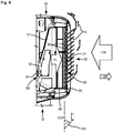
- FIG. 4 shows an enlarged view of the cooling air blower 50, the radiator 56 and the cooling air outlet 24 approximately corresponding to the in FIG. 3 dashed rectangle IV.
- the cooling air outlet 24 has ade povertyablenk Rhein 58 which is adapted to allow escaping cooling air KL flow in a predetermined direction.
- the cooling air deflection device 58 comprises a plurality of air baffles 60.
- the air baffles 60 extend in a substantially vertical direction from an upper edge 62 of the cooling air outlet 24 to a lower edge 64 of the cooling air outlet 24 (see FIG Fig. 1 ).
- the air baffles 60 are arranged inclined.
- an acute angle ⁇ is formed between the imaginary straight line and the air guide plates 60, this angle being measured on that side 61 of the air guide plates 60 which faces away from the first vehicle side 18.
- the angle is about 25 ° to 60 °, preferably about 35 ° to 50 °. In the present example, the angle is about 44 ° to 46 °.
- the imaginary straight line GG runs essentially horizontally and parallel to the vehicle front axle 34, which in FIG. 3 it can be seen, wherein the vehicle front axle 34 is represented by a dot-dash line.
- the internal combustion engine 48 is installed with its drive axis AA in the longitudinal direction of the working vehicle 10, which allows a relation to the longitudinal axis LA of the working vehicle 10 laterally offset installation.
- the internal combustion engine 48 is arranged closer to the first vehicle side 18, where the cooling air inlet 20 is arranged, so that inflowing cooling air KL, equal to the internal combustion engine 48 flows around.
- the operating station 12 can be rotatable by 180 °, such that it can be aligned and locked either in the main direction of travel HR or counter to the main direction of travel HR.
- the operator station 12 can be aligned according to the needs to be carried out depending on the work or route to be performed.
- the operating station 12 is protected or surrounded by the cabin 14.
- the operator station 12 is rotatable relative to the cabin 14. That is, the car 14 remains firmly connected to the work vehicle 10 and its body, while the operator station 12 can be rotated together with appropriate controls such as steering wheel, foot pedals and other controls.
Landscapes
- Engineering & Computer Science (AREA)
- Chemical & Material Sciences (AREA)
- Combustion & Propulsion (AREA)
- Mechanical Engineering (AREA)
- General Engineering & Computer Science (AREA)
- Transportation (AREA)
- Cooling, Air Intake And Gas Exhaust, And Fuel Tank Arrangements In Propulsion Units (AREA)
Priority Applications (3)
| Application Number | Priority Date | Filing Date | Title |
|---|---|---|---|
| ES18168563T ES2905862T3 (es) | 2018-04-20 | 2018-04-20 | Vehículo de trabajo con un deflector de aire de refrigeración en el lado de salida |
| EP18168563.7A EP3556593B1 (fr) | 2018-04-20 | 2018-04-20 | Véhicule de travail doté d'un dispositif déflecteur d'air de refroidissement côté sortie |
| US16/386,224 US11143086B2 (en) | 2018-04-20 | 2019-04-16 | Working vehicle having an outlet-side cooling-air deflection installation |
Applications Claiming Priority (1)
| Application Number | Priority Date | Filing Date | Title |
|---|---|---|---|
| EP18168563.7A EP3556593B1 (fr) | 2018-04-20 | 2018-04-20 | Véhicule de travail doté d'un dispositif déflecteur d'air de refroidissement côté sortie |
Publications (2)
| Publication Number | Publication Date |
|---|---|
| EP3556593A1 true EP3556593A1 (fr) | 2019-10-23 |
| EP3556593B1 EP3556593B1 (fr) | 2022-01-19 |
Family
ID=62110860
Family Applications (1)
| Application Number | Title | Priority Date | Filing Date |
|---|---|---|---|
| EP18168563.7A Active EP3556593B1 (fr) | 2018-04-20 | 2018-04-20 | Véhicule de travail doté d'un dispositif déflecteur d'air de refroidissement côté sortie |
Country Status (3)
| Country | Link |
|---|---|
| US (1) | US11143086B2 (fr) |
| EP (1) | EP3556593B1 (fr) |
| ES (1) | ES2905862T3 (fr) |
Citations (5)
| Publication number | Priority date | Publication date | Assignee | Title |
|---|---|---|---|---|
| US3786891A (en) * | 1969-08-25 | 1974-01-22 | Deere & Co | Engine enclosure for a harvesting machine |
| EP0468322A1 (fr) * | 1990-07-23 | 1992-01-29 | Deere & Company | Capotage de moteur de véhicule |
| US20030057005A1 (en) * | 2001-09-21 | 2003-03-27 | Kubota Corporation | Engine enclosure |
| EP1571046A1 (fr) * | 2004-03-01 | 2005-09-07 | Kobelco Construction Machinery Co., Ltd. | Engin de travaux publics |
| EP3211141A2 (fr) * | 2016-02-24 | 2017-08-30 | Wacker Neuson Linz GmbH | Camion-benne avec châssis articulé et poste de conduite réversible |
Family Cites Families (5)
| Publication number | Priority date | Publication date | Assignee | Title |
|---|---|---|---|---|
| CA949393A (en) | 1972-02-24 | 1974-06-18 | Northern Electric Company Limited | Continuous soldering apparatus and method |
| JPH08119146A (ja) * | 1994-10-24 | 1996-05-14 | Kubota Corp | 作業車 |
| US6142108A (en) * | 1998-12-16 | 2000-11-07 | Caterpillar Inc. | Temperature control system for use with an enclosure which houses an internal combustion engine |
| EP2604460B1 (fr) * | 2011-12-13 | 2016-04-13 | CNH Industrial Italia S.p.A. | Véhicule de travail ayant un système de refroidissement avec un écoulement d'air réversible |
| US10358789B2 (en) | 2016-02-26 | 2019-07-23 | Yanmar Co., Ltd. | Loader attachment system |
-
2018
- 2018-04-20 EP EP18168563.7A patent/EP3556593B1/fr active Active
- 2018-04-20 ES ES18168563T patent/ES2905862T3/es active Active
-
2019
- 2019-04-16 US US16/386,224 patent/US11143086B2/en active Active
Patent Citations (5)
| Publication number | Priority date | Publication date | Assignee | Title |
|---|---|---|---|---|
| US3786891A (en) * | 1969-08-25 | 1974-01-22 | Deere & Co | Engine enclosure for a harvesting machine |
| EP0468322A1 (fr) * | 1990-07-23 | 1992-01-29 | Deere & Company | Capotage de moteur de véhicule |
| US20030057005A1 (en) * | 2001-09-21 | 2003-03-27 | Kubota Corporation | Engine enclosure |
| EP1571046A1 (fr) * | 2004-03-01 | 2005-09-07 | Kobelco Construction Machinery Co., Ltd. | Engin de travaux publics |
| EP3211141A2 (fr) * | 2016-02-24 | 2017-08-30 | Wacker Neuson Linz GmbH | Camion-benne avec châssis articulé et poste de conduite réversible |
Also Published As
| Publication number | Publication date |
|---|---|
| US20190323412A1 (en) | 2019-10-24 |
| EP3556593B1 (fr) | 2022-01-19 |
| US11143086B2 (en) | 2021-10-12 |
| ES2905862T3 (es) | 2022-04-12 |
Similar Documents
| Publication | Publication Date | Title |
|---|---|---|
| EP1753943B1 (fr) | Systeme de refroidissement | |
| DE2941093C2 (de) | Kranfahrzeug, insbesondere Lastkraftwagen mit einer Kühlanlage für einen Verbrennungsmotor | |
| DE102013209380B4 (de) | Kühlmechanismus für ein Batteriepack eines Hybridfahrzeugs | |
| DE112014004618B4 (de) | Fortbewegungsmittel mit Brennstoffzelle | |
| WO2013149876A1 (fr) | Véhicule automobile muni d'un habillage de dessous de caisse | |
| DE10235192A1 (de) | Kühlsystem für Fahrzeuge und Verfahren zum Steuern mindestens eines einen Kühler durchströmenden Luftmassenstroms | |
| DE102013202277A1 (de) | Arbeitsmaschine | |
| EP0200899B1 (fr) | Dispositif pour la ventilation et la climatisation des postes ou cabines de conducteur | |
| EP2479398A1 (fr) | Système de gaz d'échappement pour un engin | |
| DE2941014A1 (de) | Kraftfahrzeug, insbesondere lastkraftwagen, mit einer kuehleinrichtung fuer einen vebrennungsmotor | |
| DE202007003326U1 (de) | Straßenfertiger | |
| DE102009042269A1 (de) | Klimaanlage | |
| EP2921327A2 (fr) | Cabine de conducteur d'une machine-outil à usage agricole ou dans les travaux publics | |
| EP1228907B1 (fr) | Appareil de climatisation pour véhicule automobile | |
| DE102020004615A1 (de) | Schemelgelenkte tandemwalze und verfahren zum betrieb derartiger walzen | |
| CH708786A2 (de) | Kraftfahrzeug mit einer Zusatzkühlung. | |
| EP3556593B1 (fr) | Véhicule de travail doté d'un dispositif déflecteur d'air de refroidissement côté sortie | |
| EP3144495B1 (fr) | Engin agricole | |
| DE102006044952B4 (de) | Vorrichtung zur Luftkühlung einer Radbremse an einem Kraftfahrzeug | |
| DE112013000377T5 (de) | Arbeitsfahrzeug | |
| DE102008061538A1 (de) | Kanalanordnung zum Führen von Prozessluft zu einer Verbrennungskraftmaschine | |
| EP3318433B1 (fr) | Véhicule doté d'une ventilation de véhicule | |
| DE102007054854A1 (de) | Einrichtung zur Kühlung eines Bauteiles an einem Kraftfahrzeug | |
| DE112015000025T5 (de) | Hydraulikbagger | |
| DE102016009064B4 (de) | Fahrzeug |
Legal Events
| Date | Code | Title | Description |
|---|---|---|---|
| PUAI | Public reference made under article 153(3) epc to a published international application that has entered the european phase |
Free format text: ORIGINAL CODE: 0009012 |
|
| STAA | Information on the status of an ep patent application or granted ep patent |
Free format text: STATUS: THE APPLICATION HAS BEEN PUBLISHED |
|
| AK | Designated contracting states |
Kind code of ref document: A1 Designated state(s): AL AT BE BG CH CY CZ DE DK EE ES FI FR GB GR HR HU IE IS IT LI LT LU LV MC MK MT NL NO PL PT RO RS SE SI SK SM TR |
|
| AX | Request for extension of the european patent |
Extension state: BA ME |
|
| STAA | Information on the status of an ep patent application or granted ep patent |
Free format text: STATUS: REQUEST FOR EXAMINATION WAS MADE |
|
| 17P | Request for examination filed |
Effective date: 20200416 |
|
| RBV | Designated contracting states (corrected) |
Designated state(s): AL AT BE BG CH CY CZ DE DK EE ES FI FR GB GR HR HU IE IS IT LI LT LU LV MC MK MT NL NO PL PT RO RS SE SI SK SM TR |
|
| GRAJ | Information related to disapproval of communication of intention to grant by the applicant or resumption of examination proceedings by the epo deleted |
Free format text: ORIGINAL CODE: EPIDOSDIGR1 |
|
| STAA | Information on the status of an ep patent application or granted ep patent |
Free format text: STATUS: GRANT OF PATENT IS INTENDED |
|
| GRAP | Despatch of communication of intention to grant a patent |
Free format text: ORIGINAL CODE: EPIDOSNIGR1 |
|
| RIC1 | Information provided on ipc code assigned before grant |
Ipc: B60K 11/08 20060101ALI20210729BHEP Ipc: B60R 19/52 20060101ALI20210729BHEP Ipc: B60P 1/04 20060101ALI20210729BHEP Ipc: F01P 11/10 20060101ALI20210729BHEP Ipc: B60K 11/06 20060101AFI20210729BHEP |
|
| INTG | Intention to grant announced |
Effective date: 20210901 |
|
| GRAS | Grant fee paid |
Free format text: ORIGINAL CODE: EPIDOSNIGR3 |
|
| GRAA | (expected) grant |
Free format text: ORIGINAL CODE: 0009210 |
|
| STAA | Information on the status of an ep patent application or granted ep patent |
Free format text: STATUS: THE PATENT HAS BEEN GRANTED |
|
| AK | Designated contracting states |
Kind code of ref document: B1 Designated state(s): AL AT BE BG CH CY CZ DE DK EE ES FI FR GB GR HR HU IE IS IT LI LT LU LV MC MK MT NL NO PL PT RO RS SE SI SK SM TR |
|
| REG | Reference to a national code |
Ref country code: GB Ref legal event code: FG4D Free format text: NOT ENGLISH |
|
| REG | Reference to a national code |
Ref country code: CH Ref legal event code: EP |
|
| REG | Reference to a national code |
Ref country code: DE Ref legal event code: R096 Ref document number: 502018008552 Country of ref document: DE |
|
| REG | Reference to a national code |
Ref country code: AT Ref legal event code: REF Ref document number: 1463604 Country of ref document: AT Kind code of ref document: T Effective date: 20220215 |
|
| REG | Reference to a national code |
Ref country code: IE Ref legal event code: FG4D Free format text: LANGUAGE OF EP DOCUMENT: GERMAN |
|
| REG | Reference to a national code |
Ref country code: ES Ref legal event code: FG2A Ref document number: 2905862 Country of ref document: ES Kind code of ref document: T3 Effective date: 20220412 |
|
| REG | Reference to a national code |
Ref country code: LT Ref legal event code: MG9D |
|
| REG | Reference to a national code |
Ref country code: NL Ref legal event code: MP Effective date: 20220119 |
|
| PG25 | Lapsed in a contracting state [announced via postgrant information from national office to epo] |
Ref country code: NL Free format text: LAPSE BECAUSE OF FAILURE TO SUBMIT A TRANSLATION OF THE DESCRIPTION OR TO PAY THE FEE WITHIN THE PRESCRIBED TIME-LIMIT Effective date: 20220119 |
|
| PG25 | Lapsed in a contracting state [announced via postgrant information from national office to epo] |
Ref country code: SE Free format text: LAPSE BECAUSE OF FAILURE TO SUBMIT A TRANSLATION OF THE DESCRIPTION OR TO PAY THE FEE WITHIN THE PRESCRIBED TIME-LIMIT Effective date: 20220119 Ref country code: RS Free format text: LAPSE BECAUSE OF FAILURE TO SUBMIT A TRANSLATION OF THE DESCRIPTION OR TO PAY THE FEE WITHIN THE PRESCRIBED TIME-LIMIT Effective date: 20220119 Ref country code: PT Free format text: LAPSE BECAUSE OF FAILURE TO SUBMIT A TRANSLATION OF THE DESCRIPTION OR TO PAY THE FEE WITHIN THE PRESCRIBED TIME-LIMIT Effective date: 20220519 Ref country code: NO Free format text: LAPSE BECAUSE OF FAILURE TO SUBMIT A TRANSLATION OF THE DESCRIPTION OR TO PAY THE FEE WITHIN THE PRESCRIBED TIME-LIMIT Effective date: 20220419 Ref country code: LT Free format text: LAPSE BECAUSE OF FAILURE TO SUBMIT A TRANSLATION OF THE DESCRIPTION OR TO PAY THE FEE WITHIN THE PRESCRIBED TIME-LIMIT Effective date: 20220119 Ref country code: HR Free format text: LAPSE BECAUSE OF FAILURE TO SUBMIT A TRANSLATION OF THE DESCRIPTION OR TO PAY THE FEE WITHIN THE PRESCRIBED TIME-LIMIT Effective date: 20220119 Ref country code: BG Free format text: LAPSE BECAUSE OF FAILURE TO SUBMIT A TRANSLATION OF THE DESCRIPTION OR TO PAY THE FEE WITHIN THE PRESCRIBED TIME-LIMIT Effective date: 20220419 |
|
| PG25 | Lapsed in a contracting state [announced via postgrant information from national office to epo] |
Ref country code: PL Free format text: LAPSE BECAUSE OF FAILURE TO SUBMIT A TRANSLATION OF THE DESCRIPTION OR TO PAY THE FEE WITHIN THE PRESCRIBED TIME-LIMIT Effective date: 20220119 Ref country code: LV Free format text: LAPSE BECAUSE OF FAILURE TO SUBMIT A TRANSLATION OF THE DESCRIPTION OR TO PAY THE FEE WITHIN THE PRESCRIBED TIME-LIMIT Effective date: 20220119 Ref country code: GR Free format text: LAPSE BECAUSE OF FAILURE TO SUBMIT A TRANSLATION OF THE DESCRIPTION OR TO PAY THE FEE WITHIN THE PRESCRIBED TIME-LIMIT Effective date: 20220420 Ref country code: FI Free format text: LAPSE BECAUSE OF FAILURE TO SUBMIT A TRANSLATION OF THE DESCRIPTION OR TO PAY THE FEE WITHIN THE PRESCRIBED TIME-LIMIT Effective date: 20220119 |
|
| PG25 | Lapsed in a contracting state [announced via postgrant information from national office to epo] |
Ref country code: IS Free format text: LAPSE BECAUSE OF FAILURE TO SUBMIT A TRANSLATION OF THE DESCRIPTION OR TO PAY THE FEE WITHIN THE PRESCRIBED TIME-LIMIT Effective date: 20220519 |
|
| REG | Reference to a national code |
Ref country code: DE Ref legal event code: R097 Ref document number: 502018008552 Country of ref document: DE |
|
| PG25 | Lapsed in a contracting state [announced via postgrant information from national office to epo] |
Ref country code: SM Free format text: LAPSE BECAUSE OF FAILURE TO SUBMIT A TRANSLATION OF THE DESCRIPTION OR TO PAY THE FEE WITHIN THE PRESCRIBED TIME-LIMIT Effective date: 20220119 Ref country code: SK Free format text: LAPSE BECAUSE OF FAILURE TO SUBMIT A TRANSLATION OF THE DESCRIPTION OR TO PAY THE FEE WITHIN THE PRESCRIBED TIME-LIMIT Effective date: 20220119 Ref country code: RO Free format text: LAPSE BECAUSE OF FAILURE TO SUBMIT A TRANSLATION OF THE DESCRIPTION OR TO PAY THE FEE WITHIN THE PRESCRIBED TIME-LIMIT Effective date: 20220119 Ref country code: EE Free format text: LAPSE BECAUSE OF FAILURE TO SUBMIT A TRANSLATION OF THE DESCRIPTION OR TO PAY THE FEE WITHIN THE PRESCRIBED TIME-LIMIT Effective date: 20220119 Ref country code: DK Free format text: LAPSE BECAUSE OF FAILURE TO SUBMIT A TRANSLATION OF THE DESCRIPTION OR TO PAY THE FEE WITHIN THE PRESCRIBED TIME-LIMIT Effective date: 20220119 Ref country code: CZ Free format text: LAPSE BECAUSE OF FAILURE TO SUBMIT A TRANSLATION OF THE DESCRIPTION OR TO PAY THE FEE WITHIN THE PRESCRIBED TIME-LIMIT Effective date: 20220119 |
|
| PLBE | No opposition filed within time limit |
Free format text: ORIGINAL CODE: 0009261 |
|
| STAA | Information on the status of an ep patent application or granted ep patent |
Free format text: STATUS: NO OPPOSITION FILED WITHIN TIME LIMIT |
|
| PG25 | Lapsed in a contracting state [announced via postgrant information from national office to epo] |
Ref country code: AL Free format text: LAPSE BECAUSE OF FAILURE TO SUBMIT A TRANSLATION OF THE DESCRIPTION OR TO PAY THE FEE WITHIN THE PRESCRIBED TIME-LIMIT Effective date: 20220119 |
|
| 26N | No opposition filed |
Effective date: 20221020 |
|
| REG | Reference to a national code |
Ref country code: BE Ref legal event code: MM Effective date: 20220430 |
|
| PG25 | Lapsed in a contracting state [announced via postgrant information from national office to epo] |
Ref country code: MC Free format text: LAPSE BECAUSE OF FAILURE TO SUBMIT A TRANSLATION OF THE DESCRIPTION OR TO PAY THE FEE WITHIN THE PRESCRIBED TIME-LIMIT Effective date: 20220119 Ref country code: LU Free format text: LAPSE BECAUSE OF NON-PAYMENT OF DUE FEES Effective date: 20220420 |
|
| PG25 | Lapsed in a contracting state [announced via postgrant information from national office to epo] |
Ref country code: SI Free format text: LAPSE BECAUSE OF FAILURE TO SUBMIT A TRANSLATION OF THE DESCRIPTION OR TO PAY THE FEE WITHIN THE PRESCRIBED TIME-LIMIT Effective date: 20220119 Ref country code: BE Free format text: LAPSE BECAUSE OF NON-PAYMENT OF DUE FEES Effective date: 20220430 |
|
| PG25 | Lapsed in a contracting state [announced via postgrant information from national office to epo] |
Ref country code: IE Free format text: LAPSE BECAUSE OF NON-PAYMENT OF DUE FEES Effective date: 20220420 |
|
| PG25 | Lapsed in a contracting state [announced via postgrant information from national office to epo] |
Ref country code: IT Free format text: LAPSE BECAUSE OF FAILURE TO SUBMIT A TRANSLATION OF THE DESCRIPTION OR TO PAY THE FEE WITHIN THE PRESCRIBED TIME-LIMIT Effective date: 20220119 |
|
| PG25 | Lapsed in a contracting state [announced via postgrant information from national office to epo] |
Ref country code: HU Free format text: LAPSE BECAUSE OF FAILURE TO SUBMIT A TRANSLATION OF THE DESCRIPTION OR TO PAY THE FEE WITHIN THE PRESCRIBED TIME-LIMIT; INVALID AB INITIO Effective date: 20180420 |
|
| PG25 | Lapsed in a contracting state [announced via postgrant information from national office to epo] |
Ref country code: MK Free format text: LAPSE BECAUSE OF FAILURE TO SUBMIT A TRANSLATION OF THE DESCRIPTION OR TO PAY THE FEE WITHIN THE PRESCRIBED TIME-LIMIT Effective date: 20220119 Ref country code: CY Free format text: LAPSE BECAUSE OF FAILURE TO SUBMIT A TRANSLATION OF THE DESCRIPTION OR TO PAY THE FEE WITHIN THE PRESCRIBED TIME-LIMIT Effective date: 20220119 |
|
| PG25 | Lapsed in a contracting state [announced via postgrant information from national office to epo] |
Ref country code: TR Free format text: LAPSE BECAUSE OF FAILURE TO SUBMIT A TRANSLATION OF THE DESCRIPTION OR TO PAY THE FEE WITHIN THE PRESCRIBED TIME-LIMIT Effective date: 20220119 |
|
| PG25 | Lapsed in a contracting state [announced via postgrant information from national office to epo] |
Ref country code: MT Free format text: LAPSE BECAUSE OF FAILURE TO SUBMIT A TRANSLATION OF THE DESCRIPTION OR TO PAY THE FEE WITHIN THE PRESCRIBED TIME-LIMIT Effective date: 20220119 |
|
| PGFP | Annual fee paid to national office [announced via postgrant information from national office to epo] |
Ref country code: DE Payment date: 20250417 Year of fee payment: 8 |
|
| PGFP | Annual fee paid to national office [announced via postgrant information from national office to epo] |
Ref country code: ES Payment date: 20250519 Year of fee payment: 8 |
|
| PGFP | Annual fee paid to national office [announced via postgrant information from national office to epo] |
Ref country code: FR Payment date: 20250422 Year of fee payment: 8 |
|
| PGFP | Annual fee paid to national office [announced via postgrant information from national office to epo] |
Ref country code: CH Payment date: 20250501 Year of fee payment: 8 |
|
| PGFP | Annual fee paid to national office [announced via postgrant information from national office to epo] |
Ref country code: AT Payment date: 20250416 Year of fee payment: 8 |
|
| PGFP | Annual fee paid to national office [announced via postgrant information from national office to epo] |
Ref country code: GB Payment date: 20260324 Year of fee payment: 9 |