EP3556620A1 - Soupape de commande d'une installation à air comprimé - Google Patents
Soupape de commande d'une installation à air comprimé Download PDFInfo
- Publication number
- EP3556620A1 EP3556620A1 EP19166192.5A EP19166192A EP3556620A1 EP 3556620 A1 EP3556620 A1 EP 3556620A1 EP 19166192 A EP19166192 A EP 19166192A EP 3556620 A1 EP3556620 A1 EP 3556620A1
- Authority
- EP
- European Patent Office
- Prior art keywords
- sealing ring
- control piston
- sealing
- control valve
- piston
- Prior art date
- Legal status (The legal status is an assumption and is not a legal conclusion. Google has not performed a legal analysis and makes no representation as to the accuracy of the status listed.)
- Granted
Links
Images


Classifications
-
- B—PERFORMING OPERATIONS; TRANSPORTING
- B60—VEHICLES IN GENERAL
- B60T—VEHICLE BRAKE CONTROL SYSTEMS OR PARTS THEREOF; BRAKE CONTROL SYSTEMS OR PARTS THEREOF, IN GENERAL; ARRANGEMENT OF BRAKING ELEMENTS ON VEHICLES IN GENERAL; PORTABLE DEVICES FOR PREVENTING UNWANTED MOVEMENT OF VEHICLES; VEHICLE MODIFICATIONS TO FACILITATE COOLING OF BRAKES
- B60T15/00—Construction arrangement, or operation of valves incorporated in power brake systems and not covered by groups B60T11/00 or B60T13/00
- B60T15/02—Application and release valves
- B60T15/18—Triple or other relay valves which allow step-wise application or release and which are actuated by brake-pipe pressure variation to connect brake cylinders or equivalent to compressed air or vacuum source or atmosphere
- B60T15/182—Trailer brake valves
-
- B—PERFORMING OPERATIONS; TRANSPORTING
- B60—VEHICLES IN GENERAL
- B60T—VEHICLE BRAKE CONTROL SYSTEMS OR PARTS THEREOF; BRAKE CONTROL SYSTEMS OR PARTS THEREOF, IN GENERAL; ARRANGEMENT OF BRAKING ELEMENTS ON VEHICLES IN GENERAL; PORTABLE DEVICES FOR PREVENTING UNWANTED MOVEMENT OF VEHICLES; VEHICLE MODIFICATIONS TO FACILITATE COOLING OF BRAKES
- B60T15/00—Construction arrangement, or operation of valves incorporated in power brake systems and not covered by groups B60T11/00 or B60T13/00
- B60T15/02—Application and release valves
- B60T15/025—Electrically controlled valves
- B60T15/027—Electrically controlled valves in pneumatic systems
-
- B—PERFORMING OPERATIONS; TRANSPORTING
- B60—VEHICLES IN GENERAL
- B60T—VEHICLE BRAKE CONTROL SYSTEMS OR PARTS THEREOF; BRAKE CONTROL SYSTEMS OR PARTS THEREOF, IN GENERAL; ARRANGEMENT OF BRAKING ELEMENTS ON VEHICLES IN GENERAL; PORTABLE DEVICES FOR PREVENTING UNWANTED MOVEMENT OF VEHICLES; VEHICLE MODIFICATIONS TO FACILITATE COOLING OF BRAKES
- B60T15/00—Construction arrangement, or operation of valves incorporated in power brake systems and not covered by groups B60T11/00 or B60T13/00
- B60T15/02—Application and release valves
- B60T15/18—Triple or other relay valves which allow step-wise application or release and which are actuated by brake-pipe pressure variation to connect brake cylinders or equivalent to compressed air or vacuum source or atmosphere
- B60T15/181—Trailer control valves
-
- F—MECHANICAL ENGINEERING; LIGHTING; HEATING; WEAPONS; BLASTING
- F16—ENGINEERING ELEMENTS AND UNITS; GENERAL MEASURES FOR PRODUCING AND MAINTAINING EFFECTIVE FUNCTIONING OF MACHINES OR INSTALLATIONS; THERMAL INSULATION IN GENERAL
- F16J—PISTONS; CYLINDERS; SEALINGS
- F16J15/00—Sealings
- F16J15/16—Sealings between relatively-moving surfaces
- F16J15/32—Sealings between relatively-moving surfaces with elastic sealings, e.g. O-rings
- F16J15/3204—Sealings between relatively-moving surfaces with elastic sealings, e.g. O-rings with at least one lip
- F16J15/3232—Sealings between relatively-moving surfaces with elastic sealings, e.g. O-rings with at least one lip having two or more lips
- F16J15/3236—Sealings between relatively-moving surfaces with elastic sealings, e.g. O-rings with at least one lip having two or more lips with at least one lip for each surface, e.g. U-cup packings
Definitions
- the invention relates to a control valve of a compressed air system of a vehicle, with at least one control piston, which is guided axially movable in a housing-fixed cylinder, wherein by means of the control piston, sealed via at least one arranged on the outer circumference of the control piston sealing ring, two pressure chambers are separated from each other.
- control valves are frequently used with at least one axially guided in a housing-fixed cylinder control piston.
- the control piston separates, sealed by means of at least one arranged on the outer circumference of the control piston sealing ring, two pressure chambers from each other.
- One of the pressure chambers is usually a working pressure chamber which is connected to a working pressure connection of a consumer and, depending on the axial position of the control piston, can be connected to a supply pressure connection or a venting outlet or can be shut off from both.
- the other pressure chamber may be a control pressure chamber or a compensation chamber communicating with the environment via a ventilation bore.
- the control piston can be adjusted to adjust its axial position mechanically, pneumatically or electromagnetically.
- a piston-type control valve may be used as a towing vehicle brake valve, a trailer control valve, a trailer brake valve, or a relay valve.
- a relay valve of a compressed air brake system with a pneumatically adjustable control piston is known in which the control piston is guided axially movable in a cylinder of a valve housing and a working pressure chamber separates from a control pressure chamber.
- the control pressure chamber can be acted upon by a solenoid valve alternately with a control pressure or pressure switchable.
- a radial sealing ring is used with a trained as an outer annular web attachment web in a groove formed as an annular groove in the inner wall of the cylinder, and the piston is provided with a correspondingly long, effective as a sealing surface cylindrical outer wall.
- a similar relay valve of a pneumatic brake system with a pneumatically adjustable control piston is also from the DE 10 20014 009 179 A1 known.
- the control piston is guided axially movable in a cylinder of a valve housing and also separates here a working pressure chamber from a control pressure chamber.
- a Z-shaped profiled sealing ring is inserted into an annular groove which is formed in the cylindrical outer wall of the control piston.
- For its axial guidance of the control piston is mounted by means of a central guide sleeve slidably mounted on a bearing pin fixed to the housing.
- control piston of the known control valves Due to their sliding over a central guide sleeve or a central bearing journal, the control piston of the known control valves each have an unfavorable large axial height, which in particular increases the axial dimensions of the respective control valve.
- sealing of the separated by the respective control piston pressure chambers by means of only one arranged on the outer circumference of the control piston sealing ring in the two latter embodiments of the known control valves is relatively weak.
- the present invention is therefore based on the object to propose a spool with a less axial space-requiring radial guidance and with an improved seal of the separated by the control piston pressure chambers in a piston constructed in the control valve of the type mentioned.
- the sealing ring is designed as a radial sealing ring with a substantially the axial thickness of the control piston corresponding axial width, that the sealing ring at its two axial edges in each case a radially obliquely outwards directed, abutting the inner wall of the cylinder sealing lip, and that a plurality of circumferentially distributed guide body are formed between the two sealing lips on the sealing ring.
- the invention is therefore based on a known control valve of a compressed air system of a vehicle, with at least one control piston which is guided axially movable in a housing-fixed cylinder, wherein by means of the control piston, sealed via at least one arranged on the outer circumference of the control piston sealing ring, two pressure chambers separated from each other are
- the sealing ring is designed as a radial sealing ring whose axial width substantially corresponds to the axial thickness of the control piston.
- the sealing ring in each case has a radially obliquely outwardly directed, on the inner wall of the cylinder acting as a sealing surface sealing lip, so that the separated by the control piston pressure chambers are well sealed against each other.
- Between the two sealing lips of the sealing ring are several arranged distributed circumferentially guide body or at least one circumferential guide body, by means of which the control piston is slidably guided on the inner wall of the housing-fixed cylinder.
- the sealing ring For its stable attachment to the control piston, the sealing ring according to a development on its inner side designed as a radial annular groove mounting groove which engages in the assembled state arranged on the outer circumference of the control piston, designed as a radial annular web attachment web.
- these guide bodies are preferably designed as radially raised, round guide knobs with radially outer cylindrical sliding surface, which are arranged axially centrally between the sealing lips.
- the guide body of the sealing ring is formed as a radially raised annular land with an outer cylindrical sliding surface, which is arranged axially centrally between the sealing lips and circumferentially related interruptions.
- an annular venting space via at least one arranged in the sealing ring radial vent hole with a between the sealing lips of the sealing ring and the inner wall of the Cylinder enclosed gap and with a arranged in the control piston vent passage is in communication.
- the annular venting space is preferably bounded by a radial annular groove, which is formed axially centrally in the bottom wall of the fastening groove of the sealing ring.
- annular vent space is bounded by a radial annular groove, which is formed axially centrally in the outer wall of the fastening web of the control piston.
- the vent holes in the sealing ring expediently largely circumferentially arranged centrally between the guide bodies to allow an unobstructed inflow of compressed air penetrated into the intermediate space from both axial directions.
- sealing ring with a circumferential, annular web-shaped guide body is provided that this interrupted in the vent holes of the sealing ring to allow an unobstructed inflow of compressed air penetrated into the intermediate space from both axial directions.
- the vent passage is preferably formed as a cylindrical pipe or as a ring-cylindrical pipe, which is formed centrally in or coaxially with the central axis of the control piston in the same.
- the annular venting space is then connected to the venting channel via at least one radial venting bore formed in the control piston.
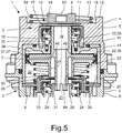
- Fig. 5 is shown in a section of a central section through a valve unit 1, which has two constructed in piston construction control valves 2, 3.
- the valve unit 1 can be used, for example, in a pneumatic brake system of a motor vehicle with two brake circuits as a trailer control valve or as a trailer brake valve.
- the valve unit 1 has a valve housing 4 which comprises an upper housing part 5 and a lower housing part 6 which are connected to one another.
- stepped cylindrical interior a largely pot-cylindrical upper housing insert 7 and a largely pot-cylindrical lower housing insert 8 are arranged immovably.
- first control valve 2 is disposed in the upper part of the valve housing 4 and has a control piston 9 and a cooperating with this sealing piston 11 of an upper seat valve 10.
- the control piston 9 is axially movably guided in a cylinder 12 of the upper housing part 5, is loaded axially upward from a compression spring 13, which is supported on a shoulder 54 of the upper housing part 5, and has on its underside a ring-shaped inner valve seat 14 of the upper seat valve 10.
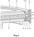
- the sealing piston 11 of the upper poppet valve 10 is axially movably guided on a cylindrical guide portion 15 of the upper housing insert 7 and of a coil spring designed as a compression spring 16 which is supported on the upper housing insert 7, axially upwards in the direction of a housing upper part 5 arranged annular ridge outer Valve seat 17 loaded.
- An enclosed by the control piston 9 in the cylinder 12 of the upper housing part 5 working pressure chamber 19 to which, for example, a leading to the wheel brake cylinders of a brake circuit brake line can be connected, is dependent on the axial position of the control piston 9 with a below the outer valve seat 17 between the upper housing part 5 and the upper housing insert 7 located annular supply pressure chamber 20 or via a central vent passage 18 with a valve housing 4 in the bottom center venting pressure chamber 21 connectable or shut off against these two pressure chambers 20, 21.
- the vent passage 18 is centrally formed in and coaxial with the center axis 53 of the control piston 22 in the same.
- the working pressure chamber 19 When the control piston 9 rests with its inner valve seat 14 on the sealing piston 11 of the upper seat valve 10 and has pushed away from the outer valve seat 17, the working pressure chamber 19 is connected to the supply pressure chamber 20 communicating with a compressed air source or a supply pressure line, so that the Working pressure in the working pressure chamber 19 is increased. If the control piston 9 has lifted with its inner valve seat 14 from the sealing piston 11 of the upper seat valve 10, and the sealing piston 11 rests against the outer valve seat 17, the working pressure chamber 19 is connected to the non-illustrated muffler with the environment in connection venting pressure chamber 21st connected, so that the working pressure in the working pressure chamber 19 is reduced.
- This in Fig. 5 completely mapped second control valve 3 is arranged in the lower part of the valve housing 4 and has a control piston 22 and a cooperating with this sealing piston 24 of a lower seat valve 23.
- the control piston 22 is axially movably guided in a cylinder 25 of the upper housing insert 7, is loaded by a coil spring designed as a compression spring 26 which is supported on the lower housing insert 8 upwards, and has on its underside a ring-web-shaped inner valve seat 27 of the lower seat valve 23 on.
- the sealing piston 24 of the lower seat valve 23 is axially movably guided on a cylindrical guide section 28 of the lower housing part 6 and by a coil spring designed as a compression spring 29 which is supported on the lower housing part 6 upwards in the direction of a arranged in the lower housing insert 8 annular web-shaped outer valve seat 30th loaded.
- An enclosed by the control piston 22 in the cylinder 25 of the upper housing insert 7 working pressure chamber 32 is dependent on the axial position of the control piston 22 with a located below the outer valve seat 30 between the lower housing insert 8 and the lower housing part 6 annular supply pressure chamber 33 or via a central opening 31st in the sealing piston 24 of the lower seat valve 23 connected to the venting pressure chamber 21 or against two pressure chambers 21, 33 shut off.
- the axial position of the control piston 22 can be adjusted by appropriately setting a control pressure effective in a control pressure space 34, for example by means of a solenoid valve.
- the control pressure chamber 34 is the working pressure chamber 32 axially enclosed by the control piston 22 in the cylinder 25 of the upper housing insert 7.
- the working pressure chamber 32 is connected to the supply pressure chamber 33 communicating with a compressed air source, so that the working pressure in the Working pressure chamber 32 is increased.
- the control piston 22 of the second control valve 3 has at the top a central tubular body 35 and below a circular disk-shaped piston body 36, which are integrally connected to each other. Within the tubular body 35 is the vent channel 18 of the first control valve 2.
- the piston body 36 separates the control pressure chamber 34 from the working pressure chamber 32 and has for sealing a arranged on its outer circumference sealing ring 37, 37 '.
- the sealing ring 37, 37 ' is formed as a radial sealing ring with a substantially the thickness of the piston body 36 corresponding axial width.
- the sealing ring 37, 37 ' has at its two axial edges in each case a radially obliquely outwardly directed first or second sealing lip 39, 40, which bear against the effective inner surface as a sealing surface 38 of the cylinder 25 of the upper housing insert 7. Between the two sealing lips 39, 40 of the sealing ring 37, 37 'with a plurality of circumferentially distributed arranged guide bodies 50 or with a circumferential guide body 51, which in Fig. 5 are not visible.
- control piston 22 is thus also on the sealing ring 37, 37 'radially guided ,
- annular venting chamber 46, 47 is formed, which has a plurality of in the sealing ring 37, 37' formed radial vent holes 45 is connected to a between the two sealing lips 39, 40 of the sealing ring 37, 37 'and the inner wall 38 of the cylinder 25 of the upper housing insert 7 enclosed space 44 and a valve disposed in the control piston 22 vent 49 in conjunction.
- the vent channel 49 is formed as a ring-cylindrical pipe, which is arranged in the lower part of the control piston 22 coaxially around the central tubular body 35 and closed at the top, and which opens downwardly open into the venting pressure chamber 21.
- the annular venting chamber 46, 47 communicates with the venting channel 49 via a plurality of radial venting bores 48 arranged in the piston body 36.
- FIG. 1 has the sealing ring 37 axially centrally between the two sealing lips 39, 40 a plurality of exemplary present four circumferentially distributed arranged guide body 50, which are formed as radially raised and round guide knobs, each with radially outer cylindrical sliding surfaces.
- the circumference largely centrally between each two adjacent guide bodies 50, a respective radial vent hole 45 is formed in the sealing ring 37, so that an inflow of about both sealing lips 39, 40 penetrated into the intermediate space 44 compressed air to the vent holes 45 is possible.
- the sealing ring 37 'axially centrally between the two sealing lips 39, 40 a circumferential guide body 51 which is formed as a radially raised annular land with an outer cylindrical sliding surface.
- this guide body 51 consists of several comparatively long ring land segments, which are slightly spaced from each other by interruptions 52.
- Distributed on the circumference are a plurality of exemplary four radial vent holes 45 formed in the sealing ring 37 ', in the region of the guide body 51 is interrupted in each case to allow an inflow of over both sealing lips 39, 40 penetrated into the gap 44 compressed air.
- annular venting space 46 is formed as a radial annular groove which is axially centrally formed in the bottom wall of the fastening groove 42 of the sealing ring 37, 37 '.
- the arranged in the sealing ring 37, 37 'vent holes 45 are characterized relatively short.
- annular venting chamber 47 is formed by a radial annular groove, which is formed axially centrally in the outer wall of the fastening web 43 of the control piston 22.
- the arranged in the sealing ring 37, 37 'vent holes 45 are therefore made slightly longer with a thicker sealing ring wall.
Landscapes
- Engineering & Computer Science (AREA)
- Transportation (AREA)
- Mechanical Engineering (AREA)
- Valves And Accessory Devices For Braking Systems (AREA)
Applications Claiming Priority (1)
| Application Number | Priority Date | Filing Date | Title |
|---|---|---|---|
| DE102018108975.9A DE102018108975A1 (de) | 2018-04-16 | 2018-04-16 | Steuerventil einer Druckluftanlage |
Publications (2)
| Publication Number | Publication Date |
|---|---|
| EP3556620A1 true EP3556620A1 (fr) | 2019-10-23 |
| EP3556620B1 EP3556620B1 (fr) | 2020-09-16 |
Family
ID=66041220
Family Applications (1)
| Application Number | Title | Priority Date | Filing Date |
|---|---|---|---|
| EP19166192.5A Active EP3556620B1 (fr) | 2018-04-16 | 2019-03-29 | Soupape de commande d'une installation à air comprimé |
Country Status (3)
| Country | Link |
|---|---|
| US (1) | US10723338B2 (fr) |
| EP (1) | EP3556620B1 (fr) |
| DE (1) | DE102018108975A1 (fr) |
Families Citing this family (14)
| Publication number | Priority date | Publication date | Assignee | Title |
|---|---|---|---|---|
| US10839203B1 (en) * | 2016-12-27 | 2020-11-17 | Amazon Technologies, Inc. | Recognizing and tracking poses using digital imagery captured from multiple fields of view |
| DE102018106975A1 (de) * | 2018-03-23 | 2019-09-26 | Wabco Gmbh | Relaisventil einer Druckluftanlage |
| US11468698B1 (en) | 2018-06-28 | 2022-10-11 | Amazon Technologies, Inc. | Associating events with actors using digital imagery and machine learning |
| US11482045B1 (en) | 2018-06-28 | 2022-10-25 | Amazon Technologies, Inc. | Associating events with actors using digital imagery and machine learning |
| US11468681B1 (en) | 2018-06-28 | 2022-10-11 | Amazon Technologies, Inc. | Associating events with actors using digital imagery and machine learning |
| US11443516B1 (en) | 2020-04-06 | 2022-09-13 | Amazon Technologies, Inc. | Locally and globally locating actors by digital cameras and machine learning |
| US12592096B1 (en) | 2020-09-30 | 2026-03-31 | Amazon Technologies, Inc. | Modeling and detecting shopping events using visual images and machine learning |
| DE102021110256A1 (de) * | 2021-04-22 | 2022-10-27 | Zf Cv Systems Europe Bv | Kolben, Verdichter, Druckluftversorgungsanlage, Fahrzeug und Verfahren zum Betreiben einer Druckluftversorgungsanlage |
| US12382179B1 (en) | 2022-03-30 | 2025-08-05 | Amazon Technologies, Inc. | Detecting events by streaming pooled location features from cameras |
| US12131539B1 (en) | 2022-06-29 | 2024-10-29 | Amazon Technologies, Inc. | Detecting interactions from features determined from sequences of images captured using one or more cameras |
| CN115342096B (zh) * | 2022-08-30 | 2025-07-29 | 盐城朋美实机械制造有限公司 | 一种活塞密封为金属包胶型的扇形旋转气缸 |
| US12518537B1 (en) | 2022-09-23 | 2026-01-06 | Amazon Technologies, Inc. | Detecting shopping events based on contents of hands depicted within images |
| US12540682B2 (en) * | 2023-04-14 | 2026-02-03 | Bendix Commercial Vehicle Systems Llc | Foot brake module with a guiding feature on a relay piston |
| US12573237B1 (en) | 2023-06-29 | 2026-03-10 | Amazon Technologies, Inc. | Detecting events by actors using dynamically cropped images |
Citations (7)
| Publication number | Priority date | Publication date | Assignee | Title |
|---|---|---|---|---|
| DE2730112A1 (de) * | 1977-07-04 | 1979-01-25 | Festo Maschf Stoll G | Kolbenanordnung, insbesondere fuer trockenlaufkompressoren, sowie verfahren zu deren herstellung |
| DE3031012A1 (de) * | 1979-12-29 | 1981-07-02 | VEB Bremshydraulik, DDR 9102 Limbach-Oberfrohna | Bremshydraulikzylinder, insbesondere fuer kraftfahrzeuge |
| GB2273541A (en) * | 1992-12-17 | 1994-06-22 | Fichtel & Sachs Ag | A hydraulic friction clutch actuator having a brake fluid and mineral oil resistant seal |
| DE10120321A1 (de) * | 2001-04-26 | 2002-11-14 | Knorr Bremse Systeme | Elektropneumatisches Regelventil mit einer Führungsanordnung für einen Steuerkolben |
| DE102008002325A1 (de) * | 2008-06-10 | 2009-12-17 | Zf Friedrichshafen Ag | Dichtelment zur Abdichtung eines Kolbens |
| DE102009040759A1 (de) | 2009-09-09 | 2011-03-10 | Wabco Gmbh | Relaisventileinrichtung |
| DE102014009179A1 (de) | 2014-06-21 | 2015-12-24 | Wabco Gmbh | Ventilanordnung |
Family Cites Families (3)
| Publication number | Priority date | Publication date | Assignee | Title |
|---|---|---|---|---|
| US553738A (en) * | 1896-01-28 | Metallic packing | ||
| DE688624C (de) * | 1937-09-11 | 1940-02-26 | Adolf Winterhoff | Dichtungsring fuer Kolben, insbesondere fuer Kolbenpumpen, von im Querschnitt W-foermigem Profil |
| BE557047A (fr) * | 1956-05-07 |
-
2018
- 2018-04-16 DE DE102018108975.9A patent/DE102018108975A1/de not_active Withdrawn
-
2019
- 2019-03-29 EP EP19166192.5A patent/EP3556620B1/fr active Active
- 2019-04-08 US US16/377,819 patent/US10723338B2/en active Active
Patent Citations (8)
| Publication number | Priority date | Publication date | Assignee | Title |
|---|---|---|---|---|
| DE2730112A1 (de) * | 1977-07-04 | 1979-01-25 | Festo Maschf Stoll G | Kolbenanordnung, insbesondere fuer trockenlaufkompressoren, sowie verfahren zu deren herstellung |
| DE3031012A1 (de) * | 1979-12-29 | 1981-07-02 | VEB Bremshydraulik, DDR 9102 Limbach-Oberfrohna | Bremshydraulikzylinder, insbesondere fuer kraftfahrzeuge |
| GB2273541A (en) * | 1992-12-17 | 1994-06-22 | Fichtel & Sachs Ag | A hydraulic friction clutch actuator having a brake fluid and mineral oil resistant seal |
| DE10120321A1 (de) * | 2001-04-26 | 2002-11-14 | Knorr Bremse Systeme | Elektropneumatisches Regelventil mit einer Führungsanordnung für einen Steuerkolben |
| DE10120321B4 (de) | 2001-04-26 | 2004-12-16 | Knorr-Bremse Systeme für Nutzfahrzeuge GmbH | Elektropneumatisches Regelventil mit einer Führungsanordnung für einen Steuerkolben |
| DE102008002325A1 (de) * | 2008-06-10 | 2009-12-17 | Zf Friedrichshafen Ag | Dichtelment zur Abdichtung eines Kolbens |
| DE102009040759A1 (de) | 2009-09-09 | 2011-03-10 | Wabco Gmbh | Relaisventileinrichtung |
| DE102014009179A1 (de) | 2014-06-21 | 2015-12-24 | Wabco Gmbh | Ventilanordnung |
Also Published As
| Publication number | Publication date |
|---|---|
| EP3556620B1 (fr) | 2020-09-16 |
| DE102018108975A1 (de) | 2019-10-17 |
| US20190315329A1 (en) | 2019-10-17 |
| US10723338B2 (en) | 2020-07-28 |
Similar Documents
| Publication | Publication Date | Title |
|---|---|---|
| EP3556620B1 (fr) | Soupape de commande d'une installation à air comprimé | |
| DE102004012526B4 (de) | Steuerventil zum Steuern der Fluidströmung in einer Hydrauliksteuereinheit | |
| EP2952365B1 (fr) | Passage tournant pour roue de véhicule | |
| DE4409252C2 (de) | Luftfederungsanlage | |
| DE69702807T2 (de) | Mehrzweck-Ventil | |
| EP0197320B1 (fr) | Pompe à pistons radiaux | |
| EP1212517B1 (fr) | Dispositif de reglage d'un arbre a cames destine a des moteurs a combustion interne | |
| DE10203886B4 (de) | Vorsteuerventil | |
| DE19919015C2 (de) | Hydraulische Ventilanordnung mit Verriegelungs- und Schwimmfunktion | |
| DE112016003470T5 (de) | Hauptzylindereinheit | |
| EP2451681A1 (fr) | Valve de commande de remorque pour un système de frein à air comprimé | |
| EP0223935B1 (fr) | Valve de commande de pression de freinage commandés par deux circuits | |
| DE69203374T2 (de) | Hydraulischer Stossdämpfer. | |
| EP4375092B1 (fr) | Ensemble valve de pression de pneu et groupe comprenant des ensembles valve de pression de pneu | |
| EP3768562A1 (fr) | Soupape à relais d'un systeme à air comprimé | |
| EP1817216B1 (fr) | Soupape a actionnement electromagnetique, en particulier dans un systeme de freinage d'un vehicule a moteur | |
| DE3443608A1 (de) | Doppelbremsventilanordnung | |
| DE10120323C1 (de) | Elektropneumatisches Regelventil mit einer Dichtungsanordnung | |
| DE3837055C2 (fr) | ||
| DE112004001028T5 (de) | Ventilsitz für ein Steuerventil in einem Fahrzeugbremssystem | |
| EP1385729A2 (fr) | Double soupape de regulation electropneumatique comportant un ensemble d'etancheite | |
| DE102013002883A1 (de) | Pneumatisches Wechselventil zur wechselweisen Versorgung beziehungsweise gleichzeitigen Entlüftung zweier Verbraucherleitungen | |
| EP4114698B1 (fr) | Valve pour fluides, agéncement de valve et systèm de freinage | |
| WO2019057373A1 (fr) | Corps de pompe d'un groupe hydraulique comportant un logement de pompe | |
| EP0151988A2 (fr) | Soupape de freinage à deux circuits |
Legal Events
| Date | Code | Title | Description |
|---|---|---|---|
| PUAI | Public reference made under article 153(3) epc to a published international application that has entered the european phase |
Free format text: ORIGINAL CODE: 0009012 |
|
| STAA | Information on the status of an ep patent application or granted ep patent |
Free format text: STATUS: THE APPLICATION HAS BEEN PUBLISHED |
|
| AK | Designated contracting states |
Kind code of ref document: A1 Designated state(s): AL AT BE BG CH CY CZ DE DK EE ES FI FR GB GR HR HU IE IS IT LI LT LU LV MC MK MT NL NO PL PT RO RS SE SI SK SM TR |
|
| AX | Request for extension of the european patent |
Extension state: BA ME |
|
| STAA | Information on the status of an ep patent application or granted ep patent |
Free format text: STATUS: REQUEST FOR EXAMINATION WAS MADE |
|
| 17P | Request for examination filed |
Effective date: 20200423 |
|
| RBV | Designated contracting states (corrected) |
Designated state(s): AL AT BE BG CH CY CZ DE DK EE ES FI FR GB GR HR HU IE IS IT LI LT LU LV MC MK MT NL NO PL PT RO RS SE SI SK SM TR |
|
| GRAP | Despatch of communication of intention to grant a patent |
Free format text: ORIGINAL CODE: EPIDOSNIGR1 |
|
| STAA | Information on the status of an ep patent application or granted ep patent |
Free format text: STATUS: GRANT OF PATENT IS INTENDED |
|
| INTG | Intention to grant announced |
Effective date: 20200619 |
|
| GRAS | Grant fee paid |
Free format text: ORIGINAL CODE: EPIDOSNIGR3 |
|
| GRAA | (expected) grant |
Free format text: ORIGINAL CODE: 0009210 |
|
| STAA | Information on the status of an ep patent application or granted ep patent |
Free format text: STATUS: THE PATENT HAS BEEN GRANTED |
|
| AK | Designated contracting states |
Kind code of ref document: B1 Designated state(s): AL AT BE BG CH CY CZ DE DK EE ES FI FR GB GR HR HU IE IS IT LI LT LU LV MC MK MT NL NO PL PT RO RS SE SI SK SM TR |
|
| REG | Reference to a national code |
Ref country code: GB Ref legal event code: FG4D Free format text: NOT ENGLISH |
|
| REG | Reference to a national code |
Ref country code: CH Ref legal event code: EP |
|
| REG | Reference to a national code |
Ref country code: DE Ref legal event code: R096 Ref document number: 502019000215 Country of ref document: DE |
|
| REG | Reference to a national code |
Ref country code: IE Ref legal event code: FG4D Free format text: LANGUAGE OF EP DOCUMENT: GERMAN |
|
| REG | Reference to a national code |
Ref country code: AT Ref legal event code: REF Ref document number: 1313916 Country of ref document: AT Kind code of ref document: T Effective date: 20201015 |
|
| PG25 | Lapsed in a contracting state [announced via postgrant information from national office to epo] |
Ref country code: FI Free format text: LAPSE BECAUSE OF FAILURE TO SUBMIT A TRANSLATION OF THE DESCRIPTION OR TO PAY THE FEE WITHIN THE PRESCRIBED TIME-LIMIT Effective date: 20200916 Ref country code: BG Free format text: LAPSE BECAUSE OF FAILURE TO SUBMIT A TRANSLATION OF THE DESCRIPTION OR TO PAY THE FEE WITHIN THE PRESCRIBED TIME-LIMIT Effective date: 20201216 Ref country code: NO Free format text: LAPSE BECAUSE OF FAILURE TO SUBMIT A TRANSLATION OF THE DESCRIPTION OR TO PAY THE FEE WITHIN THE PRESCRIBED TIME-LIMIT Effective date: 20201216 Ref country code: GR Free format text: LAPSE BECAUSE OF FAILURE TO SUBMIT A TRANSLATION OF THE DESCRIPTION OR TO PAY THE FEE WITHIN THE PRESCRIBED TIME-LIMIT Effective date: 20201217 Ref country code: SE Free format text: LAPSE BECAUSE OF FAILURE TO SUBMIT A TRANSLATION OF THE DESCRIPTION OR TO PAY THE FEE WITHIN THE PRESCRIBED TIME-LIMIT Effective date: 20200916 Ref country code: HR Free format text: LAPSE BECAUSE OF FAILURE TO SUBMIT A TRANSLATION OF THE DESCRIPTION OR TO PAY THE FEE WITHIN THE PRESCRIBED TIME-LIMIT Effective date: 20200916 |
|
| REG | Reference to a national code |
Ref country code: NL Ref legal event code: MP Effective date: 20200916 |
|
| PG25 | Lapsed in a contracting state [announced via postgrant information from national office to epo] |
Ref country code: RS Free format text: LAPSE BECAUSE OF FAILURE TO SUBMIT A TRANSLATION OF THE DESCRIPTION OR TO PAY THE FEE WITHIN THE PRESCRIBED TIME-LIMIT Effective date: 20200916 Ref country code: LV Free format text: LAPSE BECAUSE OF FAILURE TO SUBMIT A TRANSLATION OF THE DESCRIPTION OR TO PAY THE FEE WITHIN THE PRESCRIBED TIME-LIMIT Effective date: 20200916 |
|
| REG | Reference to a national code |
Ref country code: LT Ref legal event code: MG4D |
|
| PG25 | Lapsed in a contracting state [announced via postgrant information from national office to epo] |
Ref country code: SM Free format text: LAPSE BECAUSE OF FAILURE TO SUBMIT A TRANSLATION OF THE DESCRIPTION OR TO PAY THE FEE WITHIN THE PRESCRIBED TIME-LIMIT Effective date: 20200916 Ref country code: LT Free format text: LAPSE BECAUSE OF FAILURE TO SUBMIT A TRANSLATION OF THE DESCRIPTION OR TO PAY THE FEE WITHIN THE PRESCRIBED TIME-LIMIT Effective date: 20200916 Ref country code: EE Free format text: LAPSE BECAUSE OF FAILURE TO SUBMIT A TRANSLATION OF THE DESCRIPTION OR TO PAY THE FEE WITHIN THE PRESCRIBED TIME-LIMIT Effective date: 20200916 Ref country code: RO Free format text: LAPSE BECAUSE OF FAILURE TO SUBMIT A TRANSLATION OF THE DESCRIPTION OR TO PAY THE FEE WITHIN THE PRESCRIBED TIME-LIMIT Effective date: 20200916 Ref country code: PT Free format text: LAPSE BECAUSE OF FAILURE TO SUBMIT A TRANSLATION OF THE DESCRIPTION OR TO PAY THE FEE WITHIN THE PRESCRIBED TIME-LIMIT Effective date: 20210118 Ref country code: CZ Free format text: LAPSE BECAUSE OF FAILURE TO SUBMIT A TRANSLATION OF THE DESCRIPTION OR TO PAY THE FEE WITHIN THE PRESCRIBED TIME-LIMIT Effective date: 20200916 |
|
| RAP4 | Party data changed (patent owner data changed or rights of a patent transferred) |
Owner name: ZF CV SYSTEMS EUROPE BV |
|
| PG25 | Lapsed in a contracting state [announced via postgrant information from national office to epo] |
Ref country code: ES Free format text: LAPSE BECAUSE OF FAILURE TO SUBMIT A TRANSLATION OF THE DESCRIPTION OR TO PAY THE FEE WITHIN THE PRESCRIBED TIME-LIMIT Effective date: 20200916 Ref country code: AL Free format text: LAPSE BECAUSE OF FAILURE TO SUBMIT A TRANSLATION OF THE DESCRIPTION OR TO PAY THE FEE WITHIN THE PRESCRIBED TIME-LIMIT Effective date: 20200916 Ref country code: IS Free format text: LAPSE BECAUSE OF FAILURE TO SUBMIT A TRANSLATION OF THE DESCRIPTION OR TO PAY THE FEE WITHIN THE PRESCRIBED TIME-LIMIT Effective date: 20210116 Ref country code: PL Free format text: LAPSE BECAUSE OF FAILURE TO SUBMIT A TRANSLATION OF THE DESCRIPTION OR TO PAY THE FEE WITHIN THE PRESCRIBED TIME-LIMIT Effective date: 20200916 |
|
| REG | Reference to a national code |
Ref country code: DE Ref legal event code: R097 Ref document number: 502019000215 Country of ref document: DE |
|
| PG25 | Lapsed in a contracting state [announced via postgrant information from national office to epo] |
Ref country code: SK Free format text: LAPSE BECAUSE OF FAILURE TO SUBMIT A TRANSLATION OF THE DESCRIPTION OR TO PAY THE FEE WITHIN THE PRESCRIBED TIME-LIMIT Effective date: 20200916 |
|
| PLBE | No opposition filed within time limit |
Free format text: ORIGINAL CODE: 0009261 |
|
| STAA | Information on the status of an ep patent application or granted ep patent |
Free format text: STATUS: NO OPPOSITION FILED WITHIN TIME LIMIT |
|
| 26N | No opposition filed |
Effective date: 20210617 |
|
| PG25 | Lapsed in a contracting state [announced via postgrant information from national office to epo] |
Ref country code: SI Free format text: LAPSE BECAUSE OF FAILURE TO SUBMIT A TRANSLATION OF THE DESCRIPTION OR TO PAY THE FEE WITHIN THE PRESCRIBED TIME-LIMIT Effective date: 20200916 Ref country code: DK Free format text: LAPSE BECAUSE OF FAILURE TO SUBMIT A TRANSLATION OF THE DESCRIPTION OR TO PAY THE FEE WITHIN THE PRESCRIBED TIME-LIMIT Effective date: 20200916 |
|
| REG | Reference to a national code |
Ref country code: DE Ref legal event code: R081 Ref document number: 502019000215 Country of ref document: DE Owner name: ZF CV SYSTEMS EUROPE BV, BE Free format text: FORMER OWNER: WABCO EUROPE BVBA, BRUESSEL, BE |
|
| PG25 | Lapsed in a contracting state [announced via postgrant information from national office to epo] |
Ref country code: MC Free format text: LAPSE BECAUSE OF FAILURE TO SUBMIT A TRANSLATION OF THE DESCRIPTION OR TO PAY THE FEE WITHIN THE PRESCRIBED TIME-LIMIT Effective date: 20200916 Ref country code: IT Free format text: LAPSE BECAUSE OF FAILURE TO SUBMIT A TRANSLATION OF THE DESCRIPTION OR TO PAY THE FEE WITHIN THE PRESCRIBED TIME-LIMIT Effective date: 20200916 |
|
| REG | Reference to a national code |
Ref country code: BE Ref legal event code: MM Effective date: 20210331 |
|
| PG25 | Lapsed in a contracting state [announced via postgrant information from national office to epo] |
Ref country code: LU Free format text: LAPSE BECAUSE OF NON-PAYMENT OF DUE FEES Effective date: 20210329 Ref country code: IE Free format text: LAPSE BECAUSE OF NON-PAYMENT OF DUE FEES Effective date: 20210329 |
|
| PG25 | Lapsed in a contracting state [announced via postgrant information from national office to epo] |
Ref country code: BE Free format text: LAPSE BECAUSE OF NON-PAYMENT OF DUE FEES Effective date: 20210331 |
|
| REG | Reference to a national code |
Ref country code: CH Ref legal event code: PL |
|
| PG25 | Lapsed in a contracting state [announced via postgrant information from national office to epo] |
Ref country code: LI Free format text: LAPSE BECAUSE OF NON-PAYMENT OF DUE FEES Effective date: 20220331 Ref country code: CH Free format text: LAPSE BECAUSE OF NON-PAYMENT OF DUE FEES Effective date: 20220331 |
|
| PG25 | Lapsed in a contracting state [announced via postgrant information from national office to epo] |
Ref country code: NL Free format text: LAPSE BECAUSE OF NON-PAYMENT OF DUE FEES Effective date: 20200923 Ref country code: CY Free format text: LAPSE BECAUSE OF FAILURE TO SUBMIT A TRANSLATION OF THE DESCRIPTION OR TO PAY THE FEE WITHIN THE PRESCRIBED TIME-LIMIT Effective date: 20200916 |
|
| P01 | Opt-out of the competence of the unified patent court (upc) registered |
Effective date: 20230528 |
|
| PG25 | Lapsed in a contracting state [announced via postgrant information from national office to epo] |
Ref country code: HU Free format text: LAPSE BECAUSE OF FAILURE TO SUBMIT A TRANSLATION OF THE DESCRIPTION OR TO PAY THE FEE WITHIN THE PRESCRIBED TIME-LIMIT; INVALID AB INITIO Effective date: 20190329 |
|
| PG25 | Lapsed in a contracting state [announced via postgrant information from national office to epo] |
Ref country code: MK Free format text: LAPSE BECAUSE OF FAILURE TO SUBMIT A TRANSLATION OF THE DESCRIPTION OR TO PAY THE FEE WITHIN THE PRESCRIBED TIME-LIMIT Effective date: 20200916 |
|
| PG25 | Lapsed in a contracting state [announced via postgrant information from national office to epo] |
Ref country code: MT Free format text: LAPSE BECAUSE OF FAILURE TO SUBMIT A TRANSLATION OF THE DESCRIPTION OR TO PAY THE FEE WITHIN THE PRESCRIBED TIME-LIMIT Effective date: 20200916 |
|
| PGFP | Annual fee paid to national office [announced via postgrant information from national office to epo] |
Ref country code: FR Payment date: 20250210 Year of fee payment: 7 |
|
| PGFP | Annual fee paid to national office [announced via postgrant information from national office to epo] |
Ref country code: GB Payment date: 20250102 Year of fee payment: 7 |
|
| REG | Reference to a national code |
Ref country code: AT Ref legal event code: MM01 Ref document number: 1313916 Country of ref document: AT Kind code of ref document: T Effective date: 20240329 |
|
| PG25 | Lapsed in a contracting state [announced via postgrant information from national office to epo] |
Ref country code: AT Free format text: LAPSE BECAUSE OF NON-PAYMENT OF DUE FEES Effective date: 20240329 |
|
| PG25 | Lapsed in a contracting state [announced via postgrant information from national office to epo] |
Ref country code: TR Free format text: LAPSE BECAUSE OF FAILURE TO SUBMIT A TRANSLATION OF THE DESCRIPTION OR TO PAY THE FEE WITHIN THE PRESCRIBED TIME-LIMIT Effective date: 20200916 |
|
| PGFP | Annual fee paid to national office [announced via postgrant information from national office to epo] |
Ref country code: DE Payment date: 20260102 Year of fee payment: 8 |
|
| PGFP | Annual fee paid to national office [announced via postgrant information from national office to epo] |
Ref country code: AT Payment date: 20260410 Year of fee payment: 5 |