EP3556635B1 - Schienenfahrzeug und entsprechendes verkehrsverfahren - Google Patents
Schienenfahrzeug und entsprechendes verkehrsverfahren Download PDFInfo
- Publication number
- EP3556635B1 EP3556635B1 EP19169547.7A EP19169547A EP3556635B1 EP 3556635 B1 EP3556635 B1 EP 3556635B1 EP 19169547 A EP19169547 A EP 19169547A EP 3556635 B1 EP3556635 B1 EP 3556635B1
- Authority
- EP
- European Patent Office
- Prior art keywords
- actuator
- car
- chassis
- valve
- way
- Prior art date
- Legal status (The legal status is an assumption and is not a legal conclusion. Google has not performed a legal analysis and makes no representation as to the accuracy of the status listed.)
- Active
Links
Images
Classifications
-
- B—PERFORMING OPERATIONS; TRANSPORTING
- B61—RAILWAYS
- B61F—RAIL VEHICLE SUSPENSIONS, e.g. UNDERFRAMES, BOGIES OR ARRANGEMENTS OF WHEEL AXLES; RAIL VEHICLES FOR USE ON TRACKS OF DIFFERENT WIDTH; PREVENTING DERAILING OF RAIL VEHICLES; WHEEL GUARDS, OBSTRUCTION REMOVERS OR THE LIKE FOR RAIL VEHICLES
- B61F5/00—Constructional details of bogies; Connections between bogies and vehicle underframes; Arrangements or devices for adjusting or allowing self-adjustment of wheel axles or bogies when rounding curves
- B61F5/02—Arrangements permitting limited transverse relative movements between vehicle underframe or bolster and bogie; Connections between underframes and bogies
- B61F5/22—Guiding of the vehicle underframes with respect to the bogies
- B61F5/24—Means for damping or minimising the canting, skewing, pitching, or plunging movements of the underframes
-
- B—PERFORMING OPERATIONS; TRANSPORTING
- B61—RAILWAYS
- B61F—RAIL VEHICLE SUSPENSIONS, e.g. UNDERFRAMES, BOGIES OR ARRANGEMENTS OF WHEEL AXLES; RAIL VEHICLES FOR USE ON TRACKS OF DIFFERENT WIDTH; PREVENTING DERAILING OF RAIL VEHICLES; WHEEL GUARDS, OBSTRUCTION REMOVERS OR THE LIKE FOR RAIL VEHICLES
- B61F5/00—Constructional details of bogies; Connections between bogies and vehicle underframes; Arrangements or devices for adjusting or allowing self-adjustment of wheel axles or bogies when rounding curves
- B61F5/02—Arrangements permitting limited transverse relative movements between vehicle underframe or bolster and bogie; Connections between underframes and bogies
- B61F5/14—Side bearings
- B61F5/144—Side bearings comprising fluid damping devices
-
- B—PERFORMING OPERATIONS; TRANSPORTING
- B61—RAILWAYS
- B61F—RAIL VEHICLE SUSPENSIONS, e.g. UNDERFRAMES, BOGIES OR ARRANGEMENTS OF WHEEL AXLES; RAIL VEHICLES FOR USE ON TRACKS OF DIFFERENT WIDTH; PREVENTING DERAILING OF RAIL VEHICLES; WHEEL GUARDS, OBSTRUCTION REMOVERS OR THE LIKE FOR RAIL VEHICLES
- B61F5/00—Constructional details of bogies; Connections between bogies and vehicle underframes; Arrangements or devices for adjusting or allowing self-adjustment of wheel axles or bogies when rounding curves
- B61F5/02—Arrangements permitting limited transverse relative movements between vehicle underframe or bolster and bogie; Connections between underframes and bogies
- B61F5/04—Bolster supports or mountings
- B61F5/10—Bolster supports or mountings incorporating fluid springs
-
- B—PERFORMING OPERATIONS; TRANSPORTING
- B61—RAILWAYS
- B61F—RAIL VEHICLE SUSPENSIONS, e.g. UNDERFRAMES, BOGIES OR ARRANGEMENTS OF WHEEL AXLES; RAIL VEHICLES FOR USE ON TRACKS OF DIFFERENT WIDTH; PREVENTING DERAILING OF RAIL VEHICLES; WHEEL GUARDS, OBSTRUCTION REMOVERS OR THE LIKE FOR RAIL VEHICLES
- B61F5/00—Constructional details of bogies; Connections between bogies and vehicle underframes; Arrangements or devices for adjusting or allowing self-adjustment of wheel axles or bogies when rounding curves
- B61F5/02—Arrangements permitting limited transverse relative movements between vehicle underframe or bolster and bogie; Connections between underframes and bogies
- B61F5/22—Guiding of the vehicle underframes with respect to the bogies
- B61F5/24—Means for damping or minimising the canting, skewing, pitching, or plunging movements of the underframes
- B61F5/245—Means for damping or minimising the canting, skewing, pitching, or plunging movements of the underframes by active damping, i.e. with means to vary the damping characteristics in accordance with track or vehicle induced reactions, especially in high speed mode
Definitions
- the present invention relates to a method of circulating a railway vehicle comprising at least one car and at least one bogie carrying the car, the bogie comprising a frame and a secondary suspension system between the frame and the car, the secondary suspension system comprising a cylinder comprising two ends extending along the same axis and a device for feeding the cylinder.
- the document US 2004/016361 A1 describes a railway vehicle comprising a car, a bogie and a suspension system comprising a suspension spring and a parallel cylinder extending between the car and the bogie.
- the jack makes it possible to vary the distance between the bogie and the car, the height of the car thus being variable. This makes it possible in particular to reduce the vertical distance between the floor of the car and a platform.
- the object of the invention is in particular to remedy these drawbacks by proposing a railway vehicle comprising a suspension system having improved damping during the phases of movement of the railway vehicle.
- the invention also aims to integrate the damping function into the suspension system.
- the subject of the invention is in particular a method of running a railway vehicle according to claim 1.
- the jack is thus able to bring, then to maintain, the car and the chassis at a constant distance, for example, chosen so that the height of the floor of the car when stationary in a station is substantially equal to the height of the platform. of this station.
- the actuator participates in the damping between the car and the chassis thanks to the flow limiter.
- a railway vehicle circulation method according to the invention may further comprise one or more of the characteristics mentioned in claims 2 to 5.
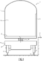
- a railway vehicle 10 stationary in a station is shown in the figure 1 .
- the station comprises at least one platform 12, such that the railway vehicle 10 is stopped along platform 12.
- the railway vehicle 10 comprises at least one car 14, at least one bogie 16 carrying the car 14.
- the car 14 has an interior volume 18 configured to receive passengers and/or goods to be transported.
- the interior volume 18 communicates with the exterior via at least one door 20.
- the interior volume 18 is in particular delimited by a lower floor 22, on which the passengers and/or the goods move.
- the bogie 16 extends for example at one end of the car 14 and supports two adjacent cars 14 when the railway vehicle 10 comprises several cars 14. According to a conventional embodiment, the or each car 14 is supported by two bogies 16 at each of its ends.
- the bogie 16 comprises wheels 24 mounted rotatably on the bogie 16 by axles 26, a frame 28 and a secondary suspension system 30 disposed between the frame 28 and the car 14.
- the wheels 24 are configured to run on rails 32 and thus allow the movement of the railway vehicle 10.
- the bogie 16 comprises four secondary suspension systems 30, located at the four corners of the bogie 16, the bogie 16 having a substantially rectangular cross-section.
- transverse is defined generally with respect to a direction substantially orthogonal to the direction of movement of the rail vehicle 10 and to a direction of elevation, for example substantially vertical when the rail vehicle 10 moves on rails 32 horizontal .
- lower and upper are defined relative to the elevation direction.
- the secondary suspension system 30 extends along a main axis X extending along the elevation direction.
- the secondary suspension system 30 makes it possible to take up the deflections according to the direction of elevation between the car 14 and the bogie 16.
- the secondary suspension system 30 makes it possible in particular to ensure both the suspension function between the car 14 and the bogie 16 and the positioning function according to the direction of elevation of the car 14 relative to the platform 12 of the station.
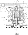
- the secondary suspension system 30, represented on the figure 2 and 3 comprises a set 34 of springs mounted between the frame 28 and the car 14, a jack 36 and a device 38 for supplying the jack 36.
- the set 34 of springs comprises at least one inner spring 40 and one outer spring 42.
- the inner spring 40 and the outer spring 42 are helical and coaxial springs, having the main axis X as their central axis.
- the diameter of the inner spring 40 is smaller than the diameter of the outer spring 42, so that the inner spring 40 extends into the internal volume defined by the outer spring 42.
- the internal spring 40 and the external spring 42 wrap around the cylinder 36.
- the inner spring 40 and the outer spring 42 have, for example, opposite winding directions.
- the set 34 of springs allows relative movement in the direction of elevation between the chassis 28 and the car 14.
- the cylinder 36 performs a function of positioning the car 14 relative to the bogie 16 in the direction of elevation.
- the cylinder 36 is capable of passing from a first configuration, called passive, in which the supply device 38 is inactive, the cylinder then being capable of passively damping the oscillations in the direction of elevation between the car 14 and the chassis 28, to a second configuration, called active, in which the supply device 38 is configured to supply the cylinder 36 in order to modify the distance between the car 14 and the chassis 28 or in order to maintain constant the distance between the car 14 and the chassis 28.
- the cylinder 36 extends along the main axis X.
- the cylinder 36 comprises a first end 44 and a second end 46 substantially aligned along the main axis X.
- the cylinder 36 further comprises an outer cylinder 48, a cylinder 50 and a piston 52 placed in the inner cylinder 50 and separating the inner cylinder 50 into an upper chamber 54 and a lower chamber 56.
- the diameter of the outer cylinder 48 is substantially greater than the diameter of the inner cylinder 50.
- the inner cylinder 50 is located within the interior volume defined by the outer cylinder 48.
- the cylinder 36 comprises two pipes 58, 60 located outside the inner cylinder 50.
- the two pipes 58, 60 are located in the volume defined between the outer cylinder 48 and the inner cylinder 50.
- the first pipe 58 communicates fluidly with the upper chamber 54 through a first passage orifice 62.
- the second pipe 60 communicates fluidly with the lower chamber 56 through a second passage orifice 63.
- the first end 44 of the actuator 36 is mechanically linked to the car 14.
- the connection between the first end 44 and the car 14 is a first ball joint 64 allowing the actuator 36 to be mobile in rotation in all the directions around the first ball joint 64 with respect to the car 14.
- the second end 46 of the cylinder 36 is mechanically linked to the frame 28.
- the connection between the second end 46 and the frame 28 is a second ball joint 65 allowing the cylinder 36 to be able to rotate in all directions. directions around the second ball joint 65 with respect to the frame 28.
- the first and second ball joints 64, 65 allow the cylinder 36 to follow the relative movements of the bogie 16 and the car 14 in the transverse and longitudinal directions, corresponding to the direction of movement of the railway vehicle 10, during the movement of the railway vehicle 10
- the cylinder 36 is not subjected to transverse forces, due to the relative movements of the bogie 16 and the car 14, these transverse forces being able to damage the cylinder 36.
- the cylinder 36 does not substantially add additional stiffness to the secondary suspension system 30.
- the first end 44 and the second end 46 are located outside the outer cylinder 48, the outer cylinder 48 being located between the first end 44 and the second end 46 along the main axis X.
- the inner cylinder 50 extends along the main axis X between a lower part 66 and an upper part 68.
- the piston 52 is movable in the inner cylinder 50 and comprises a head 70 and a rod 72 integral with the head 70.
- the head 70 is able to slide in the inner cylinder 50 along the main axis X, between the lower part 66 and the upper part 68.
- the head 70 separates the inner cylinder 50 into two chambers hermetically separated from each other, namely the upper chamber 54 and the lower chamber 56.
- the rod 72 passes through the lower part 66 of the cylinder 48 in a hermetic manner along the main axis X at the level of a third passage orifice 74 .
- the rod 72 includes the second end 46.
- the second end 46 is located opposite the head 70 with respect to the main axis X.
- Cylinder 36 advantageously comprises a position detector 75 capable of determining the position of piston 52 in inner cylinder 50.
- the position detector 75 is for example a magnetic sensor, a laser sensor or an ultrasound sensor.
- the supply device 38 is capable of supplying the jack 36 with fluid, for example oil, here having a pressure of between 50 bars and 150 bars.
- the feed device 38 is configured to control the movement of the piston 52 in the inner cylinder 50, when the actuator 36 is in the active configuration.
- the supply device 38 is in particular configured to control the displacement of the piston 52 by supplying the upper 54 and lower 56 chambers in order to increase or decrease their volume.
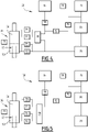
- the supply device 38 comprises a main accumulator 76, a tank 78, a pump 80, at least one flow limiter 82.
- the main accumulator 76 is capable of storing pressurized fluid.
- the main accumulator 76 is able to store 2 L of oil at a pressure of up to 150 bar.
- Reservoir 78 is able to store fluid, for example up to 5 L of oil.
- Main accumulator 76 and the reservoir 78 are fluidically connected.
- Main accumulator 76 is able to relieve its pressure to reservoir 78 by transferring fluid from main accumulator 76 to reservoir 78.
- Pump 80 is configured to circulate fluid from reservoir 78 to main accumulator 76 to pressurize main accumulator 76.
- the pump 80 is advantageously of maximum power substantially equal to 1500 W in order to be able to circulate the fluid efficiently.
- the supply device 38 is connected to the cylinder 36 by at least one flow limiter 82.
- the supply device 38 comprises two flow limiters 82, each connected respectively to the upper chamber 54 and to the lower chamber 56 of the cylinder 36.
- Each flow limiter 82 is configured to create a pressure drop when a fluid passes through the flow limiter 82.
- a flow limiter 82 is, for example, a valve having a lower fluid passage section compared to the rest of the pipes of the supply device 38. Thus, when passing through the flow limiter 82, the flow rate of the fluid passing through is reduced. and a pressure drop is created for the fluid.
- the flow restrictor 82 can therefore be considered as an obstacle for the fluid, thus acting in a manner similar to a damper.
- each flow limiter 82 is mounted in parallel with a non-return valve 84.
- Each non-return valve 84 is configured to allow the fluid to circulate only from the supply device 38 to the jack 36, without loss of pressure. The non-return valve 84 therefore prevents the circulation of fluid from the cylinder 36 to the supply device 38.
- a fluid circulating from the supply device 38 to the cylinder 36 preferentially circulates through the non-return valve 84 and a fluid circulating from the cylinder 36 to the device supply 38 flows through flow restrictor 82.
- each cylinder 36 is connected to a supply device 38.
- the various supply devices 38 are fluidly connected to each other.
- the supply circuit thus obtained advantageously comprises a single main accumulator 76, a single pump 80 and a single reservoir 78 in order to optimize the cost of the supply circuit.
- the or each supply device 38 also comprises a secondary accumulator 86, a valve, called “3-way/2-position” or more simply “3/2" 88, and at least one control valve 90.
- the secondary accumulator 86 is capable of storing pressurized fluid.
- the secondary accumulator 86 is able to store 0.5 L of oil at a pressure of up to 150 bars.
- the secondary accumulator 86 is fluidically connected to the main accumulator 76.
- the primary accumulator 76 is configured to circulate fluid to the secondary accumulator 78 to pressurize it.
- the "3/2" valve 88 comprises an inlet connected to the upper chamber 54 of the cylinder 36, a first outlet connected to the reservoir 78 and a second outlet connected to the secondary accumulator 86.
- the "3/2" valve 88 is configured to connect the inlet with the first outlet in a first "3/2" valve position 88 and connect the inlet with the second outlet in a second "3/2" valve position. 2" 88.
- Each control valve 90 is capable of allowing the fluid to circulate through said control valve 90 in a first, so-called open position and to prevent the circulation of fluid through said control valve 90 in a second, so-called closed position.
- the supply system comprises at least four control valves 90, 91, 92, 93 located respectively between the "3/2" valve 88 and the secondary accumulator 86, between the secondary accumulator 86 and the main accumulator 76, between the "3/2" valve 88 and the tank 76 and in parallel with the pump 80.
- the railway vehicle 10 runs on the rails 32 outside a station or a station comprising a platform 12.
- Cylinder 36 is in the passive configuration and feeder 38 is inactive.
- the main accumulator 76 and the secondary accumulator 86 are not under pressure.
- valves 90, 91, 92, 93 are open and allow the fluid to circulate.
- the "3/2" valve 88 is in the first position connecting the upper chamber 54 of the jack 36 to the reservoir 78.
- the upper 54 and lower 56 chambers are thus connected to the reservoir 78.
- the fluid is free to enter and exit the upper 54 and lower 56 chambers of the cylinder 36.
- the flow limiter 82 On leaving the upper 54 and lower 56 chambers, the fluid passes through the flow limiter 82, the flow limiter 82 creating a pressure drop opposing the circulation of the fluid through the flow limiter 82.
- the flow limiter 82 therefore acts as a damper for the oscillations of the piston 52 in the inner cylinder 50.
- the cylinder 36 therefore passively dampens the oscillations in the direction of elevation between the car 14 and the chassis 28 by means of the flow limiters 82.
- the railway vehicle 10 is approaching the station or the station. That is to say that the railway vehicle 10 is at a distance less than, for example, 30 m from the station or the station.
- Valve 90 is closed to isolate secondary accumulator 86 from cylinder 36.
- Valve 93 is closed so that pump 80 circulates fluid from reservoir 78 to main accumulator 76.
- the pressure in the main accumulator 76 and in the secondary accumulator 86 is regulated to achieve the desired pressure by alternately closing or opening the valves 91 and 93.
- Cylinder 36 is still in the passive configuration and passively dampens oscillations in the elevation direction between car 14 and chassis 28 by means of flow limiters 82.
- the railway vehicle 10 stops at the station along a platform 12.
- the height of the lower floor 22 is lower than the height of the platform 12 due to the mass of the car 14 and the passengers and/or goods present in the interior volume 18.
- the "3/2" valve 88 passes into its second position connecting the upper chamber 54 of the jack 36 to the secondary accumulator 86.
- the valve 90 is open in order to fluidically connect the upper chamber 54 of the cylinder 36 to the secondary accumulator 86.
- the valve 91 is opened in order to fluidically connect the secondary accumulator 86 and the main accumulator 76.
- Valves 92 and 93 are closed.
- the upper chamber 54 of the cylinder 36 increases in volume and moves the piston 52 in a direction in which the piston 52 moves away from the car 14 .
- the actuator 36 is then in the active position.
- the position of piston 52 in cylinder 36 is regulated by means of position detector 75 and by alternately closing or opening valves 91, 92, and 93.
- the jack 36 moves the car 14 away from the chassis 28 until a predetermined distance between the car 14 and the chassis 28 is reached.
- the predetermined distance between the car 14 and the chassis 28 is, for example, such that the height from the ground of the floor 22 of the car 14 is substantially equal to the height from the ground of the platform 12, that is to say that the floor 22 and platform 12 extend in the same horizontal plane.
- valves 90, 91 and 92 are then closed in order to maintain the piston 52 in a constant position and therefore to maintain the floor 22 and the platform 12 at the same height.
- Valve 93 is closed to restore main accumulator 76 to the desired pressure then valve 93 is opened so that pump 80 circulates fluid only through valve 93 and up to main accumulator 76.
- the cylinder 36 is therefore powered by the power supply device 38 so as to keep the distance between the frame 28 and the car 14 constant and to prevent the free movement of the assembly 34 of springs.
- the door 20 is then opened and the passengers and/or goods located in the interior volume 18 can then easily exit or be exited from the railway vehicle 10 through the door 20 in order to find themselves on the platform 12. And conversely passengers and/or goods initially located on the platform 12 can enter or be transported in the interior volume 18.
- valve 90 is closed to isolate upper chamber 52 from secondary accumulator 86.
- the "3/2" valve 88 goes into the first position connecting the upper chamber 54 directly to the tank 78.
- the piston 52 moves in a direction in which the piston 52 approaches the car 14.
- the distance between the car 14 and the chassis 28 decreases until reaching a position of equilibrium between the pressure of the upper chambers 54 and bass 56.
- Valves 90, 91, 92 and 93 are open.
- the actuator 36 then returns to the passive position.
- the railway vehicle 10 starts from the station and the assembly 34 of springs and the actuator 36 passively dampen the oscillations in a direction of elevation between the car 14 and the chassis 28.
- a second embodiment of the invention is shown in figure 5 and will be described below.
- a second feeder 138 different from the feeder 38 shown above, is used.
- the second supply device 138 is globally similar to the supply device 38 and differs simply in that it comprises a valve, called “4-way/3-position” or more simply “4/3" 94, instead of the “3/2” valve 88.
- the "4/3" valve 94 comprises a first inlet connected to the upper chamber 54, a second inlet connected to the lower chamber 56, a first outlet connected to the reservoir 78 and a second outlet connected to the secondary accumulator 86.
- the "4/3" valve 94 is configured to connect the first inlet with the first outlet and the second inlet with the first outlet in a first position of the "4/3” valve 94, connect the first inlet with the second outlet and the second inlet with the first outlet in a second position of the "4/3” valve 94 and connect the first inlet with the first outlet and the second inlet with the second outlet in a third position of the "4/3" valve 94 .
- the first two positions of the "4/3" valve 94 are identical to the two positions of the "3/2" valve 88.
- the third position makes it possible to connect the accumulator 86 to the lower chamber 56 and thus increase the volume of the lower chamber 56 of the cylinder 36 in order to bring the car 14 and the chassis 28 closer together.
- the second circulation process differs from the first circulation process in that during the fourth stage, the "4/3" valve 94 passes to the third position connecting the lower chamber 56 to the secondary accumulator 86 and the upper chamber 54 to the reservoir. 78.
- Valve 90 is opened so that secondary accumulator 86 puts pressure on lower chamber 56.
- Lower chamber 56 increases in volume and thus causes piston 52 to move towards car 14.
- the distance between the car 14 and the chassis 28 therefore decreases in a controlled manner thanks to the position detector 75, the pressure in the lower chamber 56 being able to be regulated by alternately opening and closing the valve 90.
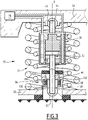
- a third embodiment of the invention is shown in picture 3 and will be described below.
- the actuator 36 further comprises a damping device 96.
- the damping device 96 is located between the second end 46 of the jack 36 and the second ball joint 65.
- the damping device 96 comprises two parts 98 and 100.
- the first part 98 is connected to the second end 46 of the actuator 36 and the second part 100 is connected to the second ball joint 65.
- the first part 98 defines a cavity 102 in which the second part 100 is able to be inserted.
- the first part 98 and the second part 100 are linked at least by a rod 104.
- the first end of the rod 104 is fixed on the first part 98.
- the second end of the rod 104 is free to slide in a channel 106 defined by the second part 100.
- the damping device 96 comprises at least one return spring 108 placed in the channel 106 and linked to the second end of the rod 104.
- the return spring 108 constrains the insertion of the second part 100 into the first part 98.
- the damping device 96 is configured to move from a first rest configuration in which the second part 100 is inserted into the first part 98, the return spring 108 being at rest, to a second position damping in which the first part 98 and the second part 100 has a deflection, the return spring 108 being compressed.
- the damping device 96 is therefore configured to take up part of the oscillations in a direction of elevation between the car 14 and the chassis 28 in order to reduce the mechanical stresses on the cylinder 36 and thus extend its life.
Landscapes
- Engineering & Computer Science (AREA)
- Mechanical Engineering (AREA)
- Vehicle Body Suspensions (AREA)
Claims (5)
- Verfahren zum Fahren eines Schienenfahrzeugs (10), umfassend mindestens einen Wagen (14) und mindestens ein Drehgestell (16), das den Wagen (14) trägt, das Drehgestell (16) umfassend einen Rahmen (28) und ein sekundäres Aufhängungssystem (30) zwischen dem Rahmen (28) und dem Wagen (14), das sekundäre Aufhängungssystem (30) umfassend:- einen Zylinder (36), umfassend zwei Enden (44, 46), die sich entlang einer gleichen Achse (X) erstrecken; und- eine Zuführvorrichtung (38) des Zylinders (36);wobei der Zylinder (36) über mindestens einen Durchflussbegrenzer (82) fluidisch mit der Zuführvorrichtung (38) verbunden ist, undwobei der Zylinder (36) konfiguriert ist, um von einer ersten, sogenannten passiven Konfiguration, in der die Zuführvorrichtung (38) inaktiv ist, wobei der Zylinder (36) dann geeignet ist, die Schwingungen entlang einer Höhenrichtung zwischen dem Wagen (14) und dem Fahrgestell (28) mittels des Durchflussbegrenzers (82) passiv zu dämpfen, zu einer zweiten, sogenannten aktiven Konfiguration überzugehen, in der die Zuführvorrichtung (38) konfiguriert ist, um den Zylinder (36) zu versorgen, um den Abstand zwischen dem Wagen (14) und dem Fahrgestell (28) zu ändern oder um den Abstand zwischen dem Wagen (14) und dem Fahrgestell (28) konstant zu halten,das Verfahren umfassend die folgenden Schritte:- Fahren des Schienenfahrzeugs (10), wobei der Zylinder (36) in einer passiven Konfiguration ist und die Schwingungen in der Aufwärtsrichtung zwischen dem Wagen (14) und dem Fahrgestell (28) zu dämpfen,- Anhalten des Schienenfahrzeugs (10) an einem Bahnsteig, wobei der Zylinder (36) in einer aktiven Konfiguration ist und von der Zuführvorrichtung (38) versorgt wird, um den Abstand zwischen dem Wagen (14) und dem Fahrgestell (28) zu ändern oder den Abstand zwischen dem Fahrgestell (28) und dem Wagen (14) konstant zu halten,wobei der Zylinder (36) mindestens einen Zylinder (50) und einen Kolben (52) umfasst, der den Zylinder (50) in eine obere Kammer (54) und eine untere Kammer (56) unterteilt, wobei die Zuführvorrichtung (38) des Zylinders (36) konfiguriert ist, um die obere Kammer (54) und die untere Kammer (56) zu versorgen,wobei die Zuführvorrichtung (38) mindestens einen Akkumulator (76, 86), der geeignet ist, um Fluid unter Druck zu speichern, und einen Behälter (78) zur Druckentlastung umfasst,und wobei:- die obere Kammer (54) des Zylinders (36) über ein sogenanntes "3-Wege/2-Stellungs"-Ventil (88) mit der Zuführvorrichtung (38) verbunden ist, wobei das "3-Wege/2-Stellungs"-Ventil (88) einen mit der oberen Kammer (54) des Zylinders (36) verbundenen Eingang, einen mit dem Behälter (78) verbundenen ersten Ausgang und einen mit dem Speicher (76, 86) aufweist, wobei das "3-Wege/2-Stellungs"-Ventil (88) in einer ersten Stellung des "3-Wege/2-Stellungs"-Ventils (88) den Eingang mit dem ersten Ausgang oder in einer zweiten Stellung des "3-Wege/2-Stellungs"-Ventils (88) mit dem zweiten Ausgang verbindet, oder- der Zylinder (36) über ein sogenanntes "4-Wege/3-Stellungs"-Ventil (94) mit der Zuführvorrichtung (38) verbunden ist, wobei das "4-Wege/3-Stellungs"-Ventil (94) einen ersten Eingang, der mit der oberen Kammer (54) des Zylinders (36) verbunden ist, einen zweiten Eingang, der mit der unteren Kammer (56) des Zylinders (36) verbunden ist, einen ersten Ausgang, der mit dem Behälter (78) verbunden ist, und einen zweiten Ausgang, der mit dem Speicher (76, 86) verbunden ist, aufweist, wobei das "4-Wege/3-Stellungs"-Ventil (94) Folgendes verbindet:∘ in einer ersten Stellung des "4-Wege/3-Stellungen"-Ventils (94) den ersten Eingang mit dem ersten Ausgang und den zweiten Eingang mit dem ersten Ausgang,∘ in einer zweiten Stellung des "4-Wege/3-Positionen" (94) den ersten Eingang mit dem zweiten Ausgang und den zweiten Eingang mit dem ersten Ausgang, oder∘ in einer dritten Position des "4-Wege/3-Stellungen"-Ventils (94) den ersten Eingang mit dem ersten Ausgang und den zweiten Eingang mit dem zweiten Ausgang.
- Fahrverfahren nach Anspruch 1, wobei das Schienenfahrzeug (10) außerdem eine Federanordnung (34) umfasst, die zwischen dem Wagen (14) und dem Fahrgestell (28) montiert ist.
- Fahrverfahren nach einem der vorherigen Ansprüche, wobei das erste Ende des Zylinders (36) über eine kugelgelenkartige Verbindung (64) mit dem Wagen (14) verbunden ist und das zweite Ende des Zylinders (36) über eine kugelgelenkartige Verbindung (65) mit dem Fahrgestell (28) verbunden ist.
- Verfahren zum Fahren nach einem der vorherigen Ansprüche, wobei der Zylinder (36) einen Positionsdetektor (75) umfasst, der geeignet ist, um die Position des Kolbens (52) in dem Zylinder (50) zu bestimmen, wobei der Positionsdetektor (75) ein Magnetsensor, ein Lasersensor oder ein Ultraschallsensor ist.
- Verfahren zum Fahren nach einem der vorherigen Ansprüche, wobei der Zylinder (36) ferner eine Dämpfungsvorrichtung (96) umfasst, wobei die Dämpfungsvorrichtung (96) den Zylinder (36) und das Fahrgestell (28) verbindet, wobei die Dämpfungsvorrichtung (96) dazu geeignet ist, um Schwingungen in der Aufwärtsrichtung zwischen dem Zylinder (36) und dem Fahrgestell (28) zu dämpfen.
Applications Claiming Priority (1)
| Application Number | Priority Date | Filing Date | Title |
|---|---|---|---|
| FR1853346A FR3080076B1 (fr) | 2018-04-17 | 2018-04-17 | Vehicule ferroviaire et procede de circulation associe |
Publications (2)
| Publication Number | Publication Date |
|---|---|
| EP3556635A1 EP3556635A1 (de) | 2019-10-23 |
| EP3556635B1 true EP3556635B1 (de) | 2022-08-17 |
Family
ID=62597739
Family Applications (1)
| Application Number | Title | Priority Date | Filing Date |
|---|---|---|---|
| EP19169547.7A Active EP3556635B1 (de) | 2018-04-17 | 2019-04-16 | Schienenfahrzeug und entsprechendes verkehrsverfahren |
Country Status (5)
| Country | Link |
|---|---|
| US (1) | US11161529B2 (de) |
| EP (1) | EP3556635B1 (de) |
| CN (1) | CN110386162B (de) |
| CA (1) | CA3039875A1 (de) |
| FR (1) | FR3080076B1 (de) |
Families Citing this family (4)
| Publication number | Priority date | Publication date | Assignee | Title |
|---|---|---|---|---|
| JP6650337B2 (ja) * | 2016-04-28 | 2020-02-19 | 川崎重工業株式会社 | 鉄道車両の輪重調整装置 |
| FR3080076B1 (fr) * | 2018-04-17 | 2020-09-18 | Alstom Transp Tech | Vehicule ferroviaire et procede de circulation associe |
| FR3115886B1 (fr) * | 2020-11-04 | 2022-12-09 | Alstom Transp Tech | Procédé de mesure d’une distance d’un véhicule à un quai |
| ES2915425A1 (es) * | 2020-12-22 | 2022-06-22 | Patentes Talgo S L U | Sistema de elevación de cajas de vehículos ferroviarios |
Family Cites Families (12)
| Publication number | Priority date | Publication date | Assignee | Title |
|---|---|---|---|---|
| CA668150A (en) * | 1963-08-06 | Manning Walter | Vehicle suspensions | |
| DE4234523A1 (de) | 1992-10-13 | 1994-04-14 | Knorr Bremse Ag | Niveau- und Neigungssteuerung eines Wagenkastens |
| US5682980A (en) * | 1996-02-06 | 1997-11-04 | Monroe Auto Equipment Company | Active suspension system |
| FR2784341B1 (fr) * | 1998-10-07 | 2000-12-15 | Alstom Technology | Dispositif d'amortissement des mouvements transversaux et de lacet d'un vehicule, et vehicule pourvu d'un tel dispositif |
| GB9912221D0 (en) * | 1999-05-26 | 1999-07-28 | Crossley Martin C | Box height adjusting system for intermodal freight vehicles |
| GB2361222B (en) * | 2000-04-15 | 2003-06-25 | Powell Duffryn Rail Ltd | Three piece bogie arrangement |
| US20040016361A1 (en) * | 2002-04-26 | 2004-01-29 | Martin Teichmann | Level control for a rail-mounted vehicle |
| US6637348B1 (en) * | 2002-07-02 | 2003-10-28 | Siemens Sgp Verkehrstechnik Gmbh | Level-adjustable main spring and actively biased emergency spring with fail-safe behavior |
| DE102008039821A1 (de) * | 2008-08-27 | 2010-03-18 | Bombardier Transportation Gmbh | Drehhemmungseinrichtung für ein Fahrzeug |
| US8079310B2 (en) * | 2009-11-25 | 2011-12-20 | LTK Consulting Services, Inc. | Vertical position compensating device for a vehicle |
| FR3080076B1 (fr) * | 2018-04-17 | 2020-09-18 | Alstom Transp Tech | Vehicule ferroviaire et procede de circulation associe |
| FR3080077B1 (fr) * | 2018-04-17 | 2020-09-18 | Alstom Transp Tech | Vehicule ferroviaire et procede de circulation associe |
-
2018
- 2018-04-17 FR FR1853346A patent/FR3080076B1/fr active Active
-
2019
- 2019-04-09 CA CA3039875A patent/CA3039875A1/fr active Pending
- 2019-04-16 CN CN201910302149.8A patent/CN110386162B/zh active Active
- 2019-04-16 US US16/385,856 patent/US11161529B2/en active Active
- 2019-04-16 EP EP19169547.7A patent/EP3556635B1/de active Active
Also Published As
| Publication number | Publication date |
|---|---|
| CN110386162A (zh) | 2019-10-29 |
| CN110386162B (zh) | 2024-04-19 |
| FR3080076B1 (fr) | 2020-09-18 |
| US20190315380A1 (en) | 2019-10-17 |
| US11161529B2 (en) | 2021-11-02 |
| FR3080076A1 (fr) | 2019-10-18 |
| CA3039875A1 (fr) | 2019-10-17 |
| EP3556635A1 (de) | 2019-10-23 |
Similar Documents
| Publication | Publication Date | Title |
|---|---|---|
| EP3556635B1 (de) | Schienenfahrzeug und entsprechendes verkehrsverfahren | |
| EP3556634B1 (de) | Schienenfahrzeug und entsprechendes verkehrsverfahren | |
| CA1241316A (fr) | Atterrisseurs pour aeronef, notamment pour helicoptere | |
| EP0280824B1 (de) | Stossdämpfer für Fahrzeug mit Luftfederung, speziell für Lastkraftwagen | |
| EP0461981A2 (de) | Feder-Dämpfer-Einheit mit veränderlichem Hub für ein Fahrzeug | |
| EP3194320B1 (de) | System zur kontrolle der bewegung einer last | |
| WO2014060705A2 (fr) | Dispositif d'assistance a une manoeuvre de porte d'un aeronef | |
| FR2950569A3 (fr) | Agencement de ressorts pour reguler le niveau dans un vehicule | |
| FR2833231A1 (fr) | Dispositif de suspension pour vehicule sur rails | |
| EP3072811A1 (de) | Luftfahrzeug und fahrwerk, das mit mindestens einem paar stossdämpfer ausgestattet ist, und verfahren zur umsetzung dieses fahrwerks | |
| FR2868493A1 (fr) | Dispositif de suspension a amortisseur hydraulique a controle d'amortissement selectif | |
| EP3254924B1 (de) | Schienenfahrzeug, das mit einem nivelliersystem ausgestattet ist, und entsprechendes verkehrsverfahren | |
| EP0893321A1 (de) | Oleopneumatische Aufhängungsvorrichtung zur Begrenzung des Wankens oder des Gierens | |
| FR2849138A1 (fr) | Amortisseur d'oscillations a force d'amortissement variable | |
| EP3620344B1 (de) | Schienenfahrzeug, das ein regulierungsorgan eines sekundären aufhängungssystems umfasst | |
| EP3620343B1 (de) | Schienenfahrzeug, das ein regulierungsorgan eines sekundären aufhängungssystems umfasst | |
| EP2152562B1 (de) | Bidirektionales führungssystem mit seitlicher schwingungsbegrenzung für eine durch eine schiene in der erde geführte strassenachse | |
| EP0045269B1 (de) | Oleopneumatische Aufhängung | |
| FR3152739A1 (fr) | Dispositif antiroulis de véhicule automobile à triple piston | |
| EP0208572B1 (de) | Automatischer Rollenstabilisator | |
| EP3708454B1 (de) | Schienenfahrzeug, das ein semiaktives stossdämpfungssystem umfasst, und entsprechendes fahrverfahren | |
| FR2766444A1 (fr) | Dispositif oleopneumatique a amortissement du roulis | |
| EP4308390B1 (de) | Hydraulische inertiale radaufhängungsvorrichtung, verfahren, stossdämpfer und fahrzeug auf der basis einer solchen vorrichtung | |
| WO1984000330A1 (fr) | Dispositif correcteur a fonctions multiples pour la suspension des vehicules | |
| WO1996015005A1 (fr) | Dispositif d'asservissement passif de la precontrainte des suspensions d'un vehicule |
Legal Events
| Date | Code | Title | Description |
|---|---|---|---|
| PUAI | Public reference made under article 153(3) epc to a published international application that has entered the european phase |
Free format text: ORIGINAL CODE: 0009012 |
|
| STAA | Information on the status of an ep patent application or granted ep patent |
Free format text: STATUS: THE APPLICATION HAS BEEN PUBLISHED |
|
| STAA | Information on the status of an ep patent application or granted ep patent |
Free format text: STATUS: REQUEST FOR EXAMINATION WAS MADE |
|
| AK | Designated contracting states |
Kind code of ref document: A1 Designated state(s): AL AT BE BG CH CY CZ DE DK EE ES FI FR GB GR HR HU IE IS IT LI LT LU LV MC MK MT NL NO PL PT RO RS SE SI SK SM TR |
|
| AX | Request for extension of the european patent |
Extension state: BA ME |
|
| 17P | Request for examination filed |
Effective date: 20191010 |
|
| RBV | Designated contracting states (corrected) |
Designated state(s): AL AT BE BG CH CY CZ DE DK EE ES FI FR GB GR HR HU IE IS IT LI LT LU LV MC MK MT NL NO PL PT RO RS SE SI SK SM TR |
|
| STAA | Information on the status of an ep patent application or granted ep patent |
Free format text: STATUS: EXAMINATION IS IN PROGRESS |
|
| 17Q | First examination report despatched |
Effective date: 20200925 |
|
| GRAP | Despatch of communication of intention to grant a patent |
Free format text: ORIGINAL CODE: EPIDOSNIGR1 |
|
| STAA | Information on the status of an ep patent application or granted ep patent |
Free format text: STATUS: GRANT OF PATENT IS INTENDED |
|
| INTG | Intention to grant announced |
Effective date: 20220328 |
|
| RIN1 | Information on inventor provided before grant (corrected) |
Inventor name: CLAVIER, JEREMY |
|
| GRAS | Grant fee paid |
Free format text: ORIGINAL CODE: EPIDOSNIGR3 |
|
| GRAA | (expected) grant |
Free format text: ORIGINAL CODE: 0009210 |
|
| STAA | Information on the status of an ep patent application or granted ep patent |
Free format text: STATUS: THE PATENT HAS BEEN GRANTED |
|
| AK | Designated contracting states |
Kind code of ref document: B1 Designated state(s): AL AT BE BG CH CY CZ DE DK EE ES FI FR GB GR HR HU IE IS IT LI LT LU LV MC MK MT NL NO PL PT RO RS SE SI SK SM TR |
|
| REG | Reference to a national code |
Ref country code: CH Ref legal event code: EP |
|
| REG | Reference to a national code |
Ref country code: DE Ref legal event code: R096 Ref document number: 602019018285 Country of ref document: DE |
|
| REG | Reference to a national code |
Ref country code: IE Ref legal event code: FG4D Free format text: LANGUAGE OF EP DOCUMENT: FRENCH |
|
| REG | Reference to a national code |
Ref country code: AT Ref legal event code: REF Ref document number: 1511987 Country of ref document: AT Kind code of ref document: T Effective date: 20220915 |
|
| REG | Reference to a national code |
Ref country code: NL Ref legal event code: MP Effective date: 20220817 |
|
| REG | Reference to a national code |
Ref country code: LT Ref legal event code: MG9D |
|
| PG25 | Lapsed in a contracting state [announced via postgrant information from national office to epo] |
Ref country code: SE Free format text: LAPSE BECAUSE OF FAILURE TO SUBMIT A TRANSLATION OF THE DESCRIPTION OR TO PAY THE FEE WITHIN THE PRESCRIBED TIME-LIMIT Effective date: 20220817 Ref country code: RS Free format text: LAPSE BECAUSE OF FAILURE TO SUBMIT A TRANSLATION OF THE DESCRIPTION OR TO PAY THE FEE WITHIN THE PRESCRIBED TIME-LIMIT Effective date: 20220817 Ref country code: PT Free format text: LAPSE BECAUSE OF FAILURE TO SUBMIT A TRANSLATION OF THE DESCRIPTION OR TO PAY THE FEE WITHIN THE PRESCRIBED TIME-LIMIT Effective date: 20221219 Ref country code: NO Free format text: LAPSE BECAUSE OF FAILURE TO SUBMIT A TRANSLATION OF THE DESCRIPTION OR TO PAY THE FEE WITHIN THE PRESCRIBED TIME-LIMIT Effective date: 20221117 Ref country code: NL Free format text: LAPSE BECAUSE OF FAILURE TO SUBMIT A TRANSLATION OF THE DESCRIPTION OR TO PAY THE FEE WITHIN THE PRESCRIBED TIME-LIMIT Effective date: 20220817 Ref country code: LV Free format text: LAPSE BECAUSE OF FAILURE TO SUBMIT A TRANSLATION OF THE DESCRIPTION OR TO PAY THE FEE WITHIN THE PRESCRIBED TIME-LIMIT Effective date: 20220817 Ref country code: LT Free format text: LAPSE BECAUSE OF FAILURE TO SUBMIT A TRANSLATION OF THE DESCRIPTION OR TO PAY THE FEE WITHIN THE PRESCRIBED TIME-LIMIT Effective date: 20220817 Ref country code: FI Free format text: LAPSE BECAUSE OF FAILURE TO SUBMIT A TRANSLATION OF THE DESCRIPTION OR TO PAY THE FEE WITHIN THE PRESCRIBED TIME-LIMIT Effective date: 20220817 |
|
| REG | Reference to a national code |
Ref country code: AT Ref legal event code: MK05 Ref document number: 1511987 Country of ref document: AT Kind code of ref document: T Effective date: 20220817 |
|
| PG25 | Lapsed in a contracting state [announced via postgrant information from national office to epo] |
Ref country code: PL Free format text: LAPSE BECAUSE OF FAILURE TO SUBMIT A TRANSLATION OF THE DESCRIPTION OR TO PAY THE FEE WITHIN THE PRESCRIBED TIME-LIMIT Effective date: 20220817 Ref country code: IS Free format text: LAPSE BECAUSE OF FAILURE TO SUBMIT A TRANSLATION OF THE DESCRIPTION OR TO PAY THE FEE WITHIN THE PRESCRIBED TIME-LIMIT Effective date: 20221217 Ref country code: HR Free format text: LAPSE BECAUSE OF FAILURE TO SUBMIT A TRANSLATION OF THE DESCRIPTION OR TO PAY THE FEE WITHIN THE PRESCRIBED TIME-LIMIT Effective date: 20220817 Ref country code: GR Free format text: LAPSE BECAUSE OF FAILURE TO SUBMIT A TRANSLATION OF THE DESCRIPTION OR TO PAY THE FEE WITHIN THE PRESCRIBED TIME-LIMIT Effective date: 20221118 |
|
| PG25 | Lapsed in a contracting state [announced via postgrant information from national office to epo] |
Ref country code: SM Free format text: LAPSE BECAUSE OF FAILURE TO SUBMIT A TRANSLATION OF THE DESCRIPTION OR TO PAY THE FEE WITHIN THE PRESCRIBED TIME-LIMIT Effective date: 20220817 Ref country code: RO Free format text: LAPSE BECAUSE OF FAILURE TO SUBMIT A TRANSLATION OF THE DESCRIPTION OR TO PAY THE FEE WITHIN THE PRESCRIBED TIME-LIMIT Effective date: 20220817 Ref country code: ES Free format text: LAPSE BECAUSE OF FAILURE TO SUBMIT A TRANSLATION OF THE DESCRIPTION OR TO PAY THE FEE WITHIN THE PRESCRIBED TIME-LIMIT Effective date: 20220817 Ref country code: DK Free format text: LAPSE BECAUSE OF FAILURE TO SUBMIT A TRANSLATION OF THE DESCRIPTION OR TO PAY THE FEE WITHIN THE PRESCRIBED TIME-LIMIT Effective date: 20220817 Ref country code: CZ Free format text: LAPSE BECAUSE OF FAILURE TO SUBMIT A TRANSLATION OF THE DESCRIPTION OR TO PAY THE FEE WITHIN THE PRESCRIBED TIME-LIMIT Effective date: 20220817 Ref country code: AT Free format text: LAPSE BECAUSE OF FAILURE TO SUBMIT A TRANSLATION OF THE DESCRIPTION OR TO PAY THE FEE WITHIN THE PRESCRIBED TIME-LIMIT Effective date: 20220817 |
|
| REG | Reference to a national code |
Ref country code: DE Ref legal event code: R097 Ref document number: 602019018285 Country of ref document: DE |
|
| PG25 | Lapsed in a contracting state [announced via postgrant information from national office to epo] |
Ref country code: SK Free format text: LAPSE BECAUSE OF FAILURE TO SUBMIT A TRANSLATION OF THE DESCRIPTION OR TO PAY THE FEE WITHIN THE PRESCRIBED TIME-LIMIT Effective date: 20220817 Ref country code: EE Free format text: LAPSE BECAUSE OF FAILURE TO SUBMIT A TRANSLATION OF THE DESCRIPTION OR TO PAY THE FEE WITHIN THE PRESCRIBED TIME-LIMIT Effective date: 20220817 |
|
| PLBE | No opposition filed within time limit |
Free format text: ORIGINAL CODE: 0009261 |
|
| STAA | Information on the status of an ep patent application or granted ep patent |
Free format text: STATUS: NO OPPOSITION FILED WITHIN TIME LIMIT |
|
| PG25 | Lapsed in a contracting state [announced via postgrant information from national office to epo] |
Ref country code: AL Free format text: LAPSE BECAUSE OF FAILURE TO SUBMIT A TRANSLATION OF THE DESCRIPTION OR TO PAY THE FEE WITHIN THE PRESCRIBED TIME-LIMIT Effective date: 20220817 |
|
| 26N | No opposition filed |
Effective date: 20230519 |
|
| PG25 | Lapsed in a contracting state [announced via postgrant information from national office to epo] |
Ref country code: SI Free format text: LAPSE BECAUSE OF FAILURE TO SUBMIT A TRANSLATION OF THE DESCRIPTION OR TO PAY THE FEE WITHIN THE PRESCRIBED TIME-LIMIT Effective date: 20220817 |
|
| P01 | Opt-out of the competence of the unified patent court (upc) registered |
Effective date: 20230823 |
|
| REG | Reference to a national code |
Ref country code: DE Ref legal event code: R119 Ref document number: 602019018285 Country of ref document: DE |
|
| REG | Reference to a national code |
Ref country code: CH Ref legal event code: PL |
|
| PG25 | Lapsed in a contracting state [announced via postgrant information from national office to epo] |
Ref country code: LU Free format text: LAPSE BECAUSE OF NON-PAYMENT OF DUE FEES Effective date: 20230416 |
|
| REG | Reference to a national code |
Ref country code: BE Ref legal event code: MM Effective date: 20230430 |
|
| PG25 | Lapsed in a contracting state [announced via postgrant information from national office to epo] |
Ref country code: MC Free format text: LAPSE BECAUSE OF FAILURE TO SUBMIT A TRANSLATION OF THE DESCRIPTION OR TO PAY THE FEE WITHIN THE PRESCRIBED TIME-LIMIT Effective date: 20220817 |
|
| PG25 | Lapsed in a contracting state [announced via postgrant information from national office to epo] |
Ref country code: MC Free format text: LAPSE BECAUSE OF FAILURE TO SUBMIT A TRANSLATION OF THE DESCRIPTION OR TO PAY THE FEE WITHIN THE PRESCRIBED TIME-LIMIT Effective date: 20220817 Ref country code: LI Free format text: LAPSE BECAUSE OF NON-PAYMENT OF DUE FEES Effective date: 20230430 Ref country code: DE Free format text: LAPSE BECAUSE OF NON-PAYMENT OF DUE FEES Effective date: 20231103 Ref country code: CH Free format text: LAPSE BECAUSE OF NON-PAYMENT OF DUE FEES Effective date: 20230430 |
|
| REG | Reference to a national code |
Ref country code: IE Ref legal event code: MM4A |
|
| PG25 | Lapsed in a contracting state [announced via postgrant information from national office to epo] |
Ref country code: BE Free format text: LAPSE BECAUSE OF NON-PAYMENT OF DUE FEES Effective date: 20230430 |
|
| PG25 | Lapsed in a contracting state [announced via postgrant information from national office to epo] |
Ref country code: IE Free format text: LAPSE BECAUSE OF NON-PAYMENT OF DUE FEES Effective date: 20230416 |
|
| PG25 | Lapsed in a contracting state [announced via postgrant information from national office to epo] |
Ref country code: IE Free format text: LAPSE BECAUSE OF NON-PAYMENT OF DUE FEES Effective date: 20230416 |
|
| PG25 | Lapsed in a contracting state [announced via postgrant information from national office to epo] |
Ref country code: IT Free format text: LAPSE BECAUSE OF FAILURE TO SUBMIT A TRANSLATION OF THE DESCRIPTION OR TO PAY THE FEE WITHIN THE PRESCRIBED TIME-LIMIT Effective date: 20220817 |
|
| PG25 | Lapsed in a contracting state [announced via postgrant information from national office to epo] |
Ref country code: BG Free format text: LAPSE BECAUSE OF FAILURE TO SUBMIT A TRANSLATION OF THE DESCRIPTION OR TO PAY THE FEE WITHIN THE PRESCRIBED TIME-LIMIT Effective date: 20220817 |
|
| PG25 | Lapsed in a contracting state [announced via postgrant information from national office to epo] |
Ref country code: BG Free format text: LAPSE BECAUSE OF FAILURE TO SUBMIT A TRANSLATION OF THE DESCRIPTION OR TO PAY THE FEE WITHIN THE PRESCRIBED TIME-LIMIT Effective date: 20220817 |
|
| REG | Reference to a national code |
Ref country code: GB Ref legal event code: 732E Free format text: REGISTERED BETWEEN 20250213 AND 20250219 |
|
| PGFP | Annual fee paid to national office [announced via postgrant information from national office to epo] |
Ref country code: FR Payment date: 20250425 Year of fee payment: 7 |
|
| PG25 | Lapsed in a contracting state [announced via postgrant information from national office to epo] |
Ref country code: CY Free format text: LAPSE BECAUSE OF FAILURE TO SUBMIT A TRANSLATION OF THE DESCRIPTION OR TO PAY THE FEE WITHIN THE PRESCRIBED TIME-LIMIT; INVALID AB INITIO Effective date: 20190416 |
|
| PG25 | Lapsed in a contracting state [announced via postgrant information from national office to epo] |
Ref country code: HU Free format text: LAPSE BECAUSE OF FAILURE TO SUBMIT A TRANSLATION OF THE DESCRIPTION OR TO PAY THE FEE WITHIN THE PRESCRIBED TIME-LIMIT; INVALID AB INITIO Effective date: 20190416 |
|
| PG25 | Lapsed in a contracting state [announced via postgrant information from national office to epo] |
Ref country code: TR Free format text: LAPSE BECAUSE OF FAILURE TO SUBMIT A TRANSLATION OF THE DESCRIPTION OR TO PAY THE FEE WITHIN THE PRESCRIBED TIME-LIMIT Effective date: 20220817 |
|
| PGFP | Annual fee paid to national office [announced via postgrant information from national office to epo] |
Ref country code: GB Payment date: 20260306 Year of fee payment: 8 |