EP3556714A1 - Commutateur de commande permettant d'opérer une grue - Google Patents
Commutateur de commande permettant d'opérer une grue Download PDFInfo
- Publication number
- EP3556714A1 EP3556714A1 EP19169574.1A EP19169574A EP3556714A1 EP 3556714 A1 EP3556714 A1 EP 3556714A1 EP 19169574 A EP19169574 A EP 19169574A EP 3556714 A1 EP3556714 A1 EP 3556714A1
- Authority
- EP
- European Patent Office
- Prior art keywords
- control panel
- housing
- control
- control switch
- crane
- Prior art date
- Legal status (The legal status is an assumption and is not a legal conclusion. Google has not performed a legal analysis and makes no representation as to the accuracy of the status listed.)
- Granted
Links
Images


Classifications
-
- B—PERFORMING OPERATIONS; TRANSPORTING
- B66—HOISTING; LIFTING; HAULING
- B66C—CRANES; LOAD-ENGAGING ELEMENTS OR DEVICES FOR CRANES, CAPSTANS, WINCHES, OR TACKLES
- B66C13/00—Other constructional features or details
- B66C13/52—Details of compartments for driving engines or motors or of operator's stands or cabins
- B66C13/54—Operator's stands or cabins
- B66C13/56—Arrangements of handles or pedals
Definitions
- the invention relates to a control switch for operating a crane according to the preamble of claim 1.
- Such a control switch is known from the brochure "CLX CHAIN HOIST - CRANE FOR EVERYDAY LIFTING" of the company Konecranes.
- This control switch is designed as a wired hanging control switch and comprises an elongated housing extending in its longitudinal direction. At a front of the housing several controls are arranged to control various functions of a connectable to the control switch crane.
- four trained in the form of buttons, provided for the crane and Katzfahrt controls are combined in a cross-shaped arrangement to a substantially diamond-shaped first control panel.
- this cross-shaped arrangement is a second control panel with two other button-shaped controls, which are provided for controlling a hoist for lifting and lowering a load.
- the controls for the hoist are arranged one behind the other in the longitudinal direction of the housing and thus vertically one above the other.
- a third control panel is provided, above which an emergency stop button is arranged with an actuating direction oriented perpendicular to the front side.
- the first section located in the region of the second control panel is made narrower relative to the second section, which is adjacent thereto and the first control panel.
- the opposite and the front side limiting longitudinal sides of the housing have in the region of the first panel and partially in the second and third panel with emergency stop button parallel to each other, with their otherwise consistently constant distance only in the area of the second panel and in the area is reduced between the first and the second panel.
- the invention has for its object to further develop a generic control switch to the effect that this has improved ergonomic properties for a particularly comfortable and safe crane operation.
- a control switch for operating a crane which comprises a housing extending in a longitudinal direction, at its front side delimited by two longitudinal sides, a first control panel is arranged with at least one control element, in particular for controlling at least one drive for horizontal crane movements, wherein at the Front side of the housing a second control panel with an emergency stop button and a third control panel with two controls, in particular for controlling vertical crane movements are arranged, improve its ergonomic properties for a particularly comfortable and safe crane operation in that the long sides in the area first control panel have a biconvex curved in the longitudinal direction of the housing to each other and thus curved in particular outward course.
- the correspondingly biconvex curved longitudinal sides extend in the region of the first control panel in the longitudinal direction of the housing in each case away from the longitudinal direction and then back to the longitudinal direction.
- the first control panel may in particular be diamond-shaped.
- the first control panel comprises at least two control elements, which are arranged side by side along a longitudinal axis of the first control panel extending parallel to the longitudinal direction of the housing and / or along a transversely to the longitudinal direction of the housing transverse axis of the first control panel.
- a vertex of each of these - viewed from the outside convex and thus biconvex to each other - curved, in particular roundish, sections of the longitudinal sides is located at the level of at least one control element or at the level of along the transverse axis side by side arranged controls and / or at the level of between the along the longitudinal axis of superimposed controls extending transverse axis.
- the apexes are therefore at the level of the opposite in the transverse direction of the housing corners of the diamond-shaped first control panel.
- the first control panel can also be achieved particularly well by the thumb of the hand holding the control switch in the area below the biconvex profile of the longitudinal sides of a person using it.
- the first control panel is in particular designed such that within the control panel up to four controls for horizontal crane movements or to control the at least one drive for the horizontal crane movements, in particular a crane drive and / or Katzfahrt of the crane, cruciform on the, in particular diamond-shaped, first control panel can be arranged.
- each control element of the first control panel as will be described in more detail with reference to the figures - in each case a corner of an imaginary rhombus of the particular diamond-shaped first control panel is arranged, wherein the intersecting diagonal of this rhombus of the longitudinal axis and transverse axis of the correspond to the first control panel, of which the longitudinal axis is parallel and the transverse axis corresponding are aligned transversely to the longitudinal direction of the control switch or its housing.
- the multifunctional operating element can thus also be arranged centrally between the longitudinal sides and in particular at a crossing point of the diagonal of the imaginary rhombus. In this case, however, no controls are then arranged in the corners of the imaginary rhombus.
- control switch or its housing including the progressions of the longitudinal sides, the arrangement of the control panels and the associated controls on a mirror-symmetrical shape with respect to an imaginary plane which is perpendicular to the front and includes the Leksachsraum the control switch or its housing. Due to the mirror symmetry, the control switch can be gripped and held by left-handers and right-handers in the same way comfortably and safely.
- a second control panel with an emergency stop button and a third control panel with two control elements are provided on the front side of the housing between the longitudinal sides in addition to the first control panel.
- the controls of the third control panel may preferably be used to control a drive for vertical crane movements, in particular a hoist, a crane connectable to the control switch.
- the first control panel - in relation to the longitudinal direction of the housing - is arranged between the second control panel and the third control panel.
- the third operating element preferably comprises two operating elements for a lifting mechanism of the crane, which are arranged one behind the other in relation to the longitudinal direction of the control switch or its housing.
- An advantageous embodiment provides that the longitudinal sides of the housing also in the region of the second control panel have a biconvex in the longitudinal direction of the housing curved course.
- the longitudinal sides in the region of the second control field also extend in the longitudinal direction of the housing, away from the longitudinal direction and then again toward the longitudinal direction.
- the longitudinal sides in the region of the second control panel thus have an outwardly convex course as well as the sections of the longitudinal sides in the region of the first control panel have a convex course.
- a radius of curvature of the convex profile in the region of the second control panel is preferably greater than a radius of curvature of the convex profile in the region of the first control panel.
- a rear side of the housing of the control switch opposite the front side has a profiled contour in the region of the first control panel and / or in the region of the third control panel.
- the profiled contour can have at least one projection which is elevated in relation to the rear side.
- the preferably extending perpendicular to the longitudinal direction of the control switch projection is provided so that a person operating the control switch can hang the index finger of one of their hands at least partially on this. In this way, an ergonomically advantageous predicament of the control switch can be brought into the hand, in which the thumb of the respective hand comfortably reach the respective, in particular the first or third, control panel and operate the local controls.
- the control switch can also be supported in the engaged state in an advantageous manner, in particular on a section of the middle finger. Without the corresponding profiled contour or the Each projection would otherwise be applied by the operator an increased holding force to prevent the control switch slides by the hand, which would also deteriorate the accessibility of the respective control panel.
- the first control panel and the third control panel are arranged together in a recessed recess opposite the front of the housing.
- the arrangement of the first and third control panel in this recess has the advantage that the controls contained do not protrude beyond the contour of the control switch or the front of the housing, whereby snagging on the controls and thus possibly associated incorrect operation can be effectively avoided.
- the arrangement of the two control panels together in a recess also has the effect that this advantageously enhances their optical and / or haptic emphasis.
- the housing has a constriction of its longitudinal sides.
- the constriction between the biconvex curved curves is arranged.
- the constriction can be located in particular in the region between the first and second control panel or in the region of the first control panel and preferably at the level of an operating element of the first control panel provided for the "crane forward" function.
- the constriction is then located between the two outwardly convex curves in the area between the first and second control panel or in the region of the first control panel and in particular in the region of the operating element for the function "crane forward".
- the two biconvex mutually curved courses in the region of the constriction waiving a possible concave course preferably directly and thus in particular crease-shaped merge into each other.
- the constriction thus resembles a prominent notch, which leads to an advantageous reinforcement of the optical and / or haptic emphasis of the individual control panels.
- the housing has a first section, which may preferably comprise the third and at least partially the first control panel, and a second section adjoining the first section in the longitudinal direction, preferably the second section Control panel may include.
- the first section and the second section are angled towards each other so that they enclose an angle between them.
- the angling of the two sections of the housing takes place around an imaginary axis running parallel to the transverse axis, so that its front side, preferably also its rear side, is curved in it.
- control switch or its housing can be provided at least partially with a soft coating.
- the soft coating coating is made by applying a multi-component paint on the housing. The goal here is primarily an improved contact with the hand enclosing the housing of a person operating the control switch. Added to this is a haptic experience in terms of quality and / or comfort in dealing with the control switch.
- the at least one projection can be rounded off towards the longitudinal sides.
- the rounding allows a seamless transition of the projection in the longitudinal sides of the housing, which further increases the ergonomics due to the lack of otherwise disturbing and / or unpleasant protruding corners of the projection.
- the rounded configuration of the at least one projection also allows the control switch to be deposited, as it were, with the rounded projection in a section of a finger, in particular of the index finger.
- the at least one projection causes an exact haptic feedback with respect to the correct position within the operator's hand.
- the projections also serve to transmit tensile forces of the operator to the crane, which can be initiated via the control switch and the control line.
- the projections allow a "hold on" of the operator on the control switch and thereby entrainment of the crane.
- the housing may have two mutually spaced projections with respect to its longitudinal direction.
- a first projection can be arranged at the height of a region which faces the third control panel and is located below two control elements of the first control panel arranged side by side along the transverse axis, while a second projection is at the height of a lower region of the third facing away from the first control panel Control panel is located.
- the distance between the two projections may be selected such that the portion of the housing located between the two projections is gripped by the ring and middle fingers of one hand while the index finger is laid above the first projection.
- the first projection serves as an orientation aid for the operator to operate the first control panel, while the second projection provides an orientation aid for the third control panel.
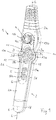
- FIG. 1 shows a perspective view of the front side 2a and a longitudinal side 2d of a control switch 1 according to the invention for operating a crane.
- the crane not shown here in detail, may in particular be an overhead crane, for example in the form of a bridge crane.
- the control switch 1 is recognizable formed as a hand control switch in the form of a suspension control switch and this includes an extending in its longitudinal direction L elongated housing 2. The usually with the control switch at its with reference to the representation of FIG. 1 Upper end arranged or can be arranged control line for connection to a crane is not apparent in the present case.
- the housing 2 is longitudinally profiled, that is to say at its opposite longitudinal sides 2c, 2d, in particular by a first convex course 13a of the longitudinal sides 2c, 2d, which is located in the region of a first control panel 3 arranged on the front side 2a with reference to FIG the longitudinal direction L of the control switch 1 respectively away from the longitudinal direction L and then extends back to the longitudinal direction L.
- the two opposite longitudinal sides 2c, 2d have a biconvex curved course 13a.
- the control switch 1 or have the longitudinal sides 2c, 2d of the housing 2, a second viewed from the outside convex course 13b in the region of a likewise arranged on the front side 2a second control panel 4.
- both opposite longitudinal sides 2c, 2d are also provided with a biconvex curved course 13b in this area.
- the two convex curves 13a, 13b seen from the outside can be seen separated from one another by a constriction 11.
- the housing 2 of the control switch 1 on its front side 2a on another third panel 5, wherein the first panel 3 between the second panel 4 and the third panel 5 is arranged.
- control switch 1 also on its rear side 2b, or on the back 2b of its housing 2, has a profiled contour. Due to the profiled contour, an ergonomically optimized gripping area is formed between the longitudinal ends 2e, 2f of the control switch 1 or its housing 2. In this gripping area, the control switch 1 can be operated by the hand of a person not shown here and the control switch 1 comfortably gripped and held to arranged on the front side 2a 2a 3d controls; 4a; 5a, 5b of the control panels 3, 4, 5 reach and operate with the thumb in particular.
- a crane By the operation of the controls 3a 3d; 4a; 5a, 5b, numerous functions of a crane can be controlled, for example, a crane drive, a Katzfahrt and lifting and lowering a hoist of the crane or its load-carrying means.
- the crane in particular including its crane girder, is moved along crane rails by means of crane bogies, which in the case of a gantry crane are fastened to the opposite ends of the crane girder.
- trolley travel a crane trolley, together with the hoist carried by the crane trolley, is moved along the crane girder by means of a trolley trolley.
- the directions of travel of the crane drive and the trolley run at right angles to each other, wherein the crane travel is transverse, in particular at right angles, to the longitudinal extent of the crane girder and the trolley travel along the longitudinal extent of the crane girder.
- the actuation of the control elements of the control switch 1 causes the generation of corresponding control signals for the respective function.
- the control signals are then sent to the crane or its control in order to trigger the respective function, for example by appropriate activation of the associated drive of the crane chassis, trolley or hoist and thereby effected execution of the desired movement.
- the control switch 1, or its housing 2 has, including the control panels 3, 4, 5 and the arrangement of the control elements 3a 3d; 4a; 5a, 5b a mirror-symmetrical shape with respect to a plane perpendicular to the plane of the Figures 3 and 4 or the front side 2a is and the longitudinal direction L of the control switch 1, or its housing 2, includes. Exceptions to this are some of the respective operating elements 3a 3d; 4a; 5a, 5b assigned different symbols and labels. Due to the mirror symmetry, the control switch 1 can be gripped and held by left-handers and right-handers in the same way comfortably and safely.
- the housing 2 is sufficient space to non-illustrated components such as a Preferably, rechargeable battery, mechanical and electrical parts of the controls and a control circuit for generating, processing and transmitting, that is sending and receiving, receive control signals to or from the control of the crane.
- the control circuit 1 can be connected to the control of the crane via a control line (not shown in more detail) in order to enable a wired signal transmission.
- the housing 2 is frontally connected at its first end 2e to the control line or already connected. The first end 2e is away from the body of an operator while holding the control switch 1 for operating a crane in his hand.
- the control switch 1 is thus connected by means of the control line and herewith to the control of the crane and thereby formed as a so-called suspension control switch.
- the three control panels 3, 4, 5 are along the longitudinal direction L of the control switch 1 and the housing 2 between the two longitudinal ends, the upper first end 2e and an opposite lower second end 2f, side by side and with respect to the usual handling of the control switch 1 insofar positioned one above the other.
- the second control panel 4 provided in the region of the first end 2e of the housing 2 comprises an operating element in the form of a pushbutton which represents an emergency stop button 4a.
- the control element or the emergency stop button 4a is preferably arranged in a concisely outstanding manner, so that a particularly fast and panic-safe triggering of an emergency stop is possible.
- the emergency stop button 4a protrudes in the present case with respect to the front side 2a of the housing 2, so that it can be grasped and operated quickly (see also FIG Figures 2 and 5 ).
- the first control panel 3 On the side facing away from the first end 2 e of the housing 2 side of the second control panel 4, the first control panel 3 is arranged on the front side 2 a, the one Control element in the form of a key 3a for the function "Crane forward" of a crane running gear, a control element in the form of a button 3b for the function "Crane reverse” of a crane landing gear, a control element in the form of a key 3c for the function "Katzfahrttim" a trolley and a control element in the form of a button 3d for the function "Katzfahrt left" of a trolley comprises.
- the round or circular and identically dimensioned controls 3a 3d are arranged in a star shape.
- the control switch 1 has on the front side 2a a recess in the housing wall, whose base corresponds substantially to the diamonds spanned by the diagonal.
- the operating elements 3a 3d are arranged in the corners of the diamond-shaped depression with a small radial distance to the recess bounding the housing wall.
- the sides or edges of the imaginary rhombus have inwardly directed, rounded indentations.
- controls 3a, 3b are so far located in end portions of the aligned parallel to the longitudinal direction L of the housing 2 first diagonal.
- the arranged along a transverse to the longitudinal direction L of the housing 2 transverse axis y of the first control panel 3 arranged controls 3c, 3d are located in end regions of the orthogonal to the first diagonal aligned second diagonal.
- the controls 3a 3d are thus arranged approximately cross-shaped and / or diamond-shaped, so that in the FIGS. 1 and 3 shown, substantially diamond-shaped first control panel 3 in the region of the recess of the housing 2 results.
- the coaxial to the longitudinal axis x and transverse axis y extending diagonals are unequal length, so that the imaginary rhombus, or the base of the recess, a rectangle or parallelogram with corresponding rounded corners and corresponding rounded edges.
- the depression is open in the direction of the second end 2f below the button 3b to the third control panel 5.
- the first control panel 3 and the third control panel 5 are thus arranged together in a continuous recess.
- the third control panel 5 is positioned on the side of the first control panel 3 facing the second end 2f of the housing 2.
- the control panel 5 comprises as control elements a button 5a for the function "lifting" a hoist and - spaced therefrom in the direction of the second end 2f - a button 5b for the function "lowering" a hoist.
- the operating elements 5a, 5b for a hoist are arranged centered along an imaginary straight line which is aligned parallel to the longitudinal direction L of the housing 2 and in particular aligned with the first diagonal or longitudinal axis x of the second control panel 4.
- control elements 5a, 5b are round or circular and the same dimensioned and arranged in the continuous from the control panel 3 without interruption, formed on the front side 2a elongated recess in the housing wall.
- the longitudinal end of the recess is rounded.
- the radius of the rounding is chosen so that those, the depression bounding housing walls are also so far away from the control element 5b that sufficient space remains for its manual actuation.
- the longitudinal end of the recess is also designed so that the thumb of an operator's hand, coming from the lower second end 2f slides on the front 2a of the control switch 1 along a slope G, in particular compared to the rest of the depression a shallower pitch has, in the recess and the third panel 5 is performed.
- all six operating elements 3a 3d; 5a, 5b of the two above-mentioned first and second control panels 3, 5 have the same dimensions and, in particular, are designed as one-or multi-stage pushbuttons. A stepless design of the push buttons is conceivable.
- the aforementioned controls 3a 3d; 4a; 5a, 5b or the vicinity of the operating elements 3a 3d; 4a; 5a, 5b on the front side 2a may be provided with symbols and / or inscriptions shown here only as examples and thus not limited thereto, which are based on the function of the respective operating element 3a 3d; 4a; 5a, 5b. Further details on the shape and arrangement of the control panels 3 5 and the associated controls 3a 3d; 4a; 5a, 5b are shown in the figures.
- the contour of the control switch 1 and the housing 2 and the previously described control panels 3 5 are ergonomically advantageous coordinated with each other as described below in terms of their shape and arrangement.
- the housing 2 of the control switch 1 between its two longitudinal ends 2e, 2f has a profiled in the longitudinal direction L shape, which preferably comprises two immediately consecutive biconvex mutually curved courses 13a, 13b of the longitudinal sides 2c, 2d and a constriction 11 located between them ,
- the convex curves 13a, 13b of the housing 2 of the control switch 1 are wider than in the constriction 11.
- the longitudinal sides extend 2c, 2d initially each away from the longitudinal direction L and then back to the longitudinal direction L in the direction of the second end 2f out.
- the second control panel 4 is arranged between the longitudinal sides 2c, 2d, which have the biconvex curved curves 13b.
- the constriction 11 then adjoins these convex curves 13b seen from the outside (see in particular FIG. 3 ).
- the further convex profiles 13a of the longitudinal sides 2c, 2d are adjacent to one another, wherein the longitudinal sides 2c, 2d in the region of the first control panel 3 with respect to the longitudinal direction L of the control switch 1 each away from the longitudinal direction L and then extend to the longitudinal direction L out.
- the longitudinal sides 2c, 2d in the sense of a bend or bend go from a biconvex curved course 13b in the next biconvex to each other curved course 13a.
- the transition or course 12 between the first biconvex curved course 13a and the straight line to the second end 2f of the control switch 1 is biconcave curved to each other and thus differs in shape from the abrupt transition of the crescent-shaped constriction 11 between the first biconvex to each other Course 13a and the second biconvex curved course 13b.
- the biconcave curved course 12 of the transition represents a less hard or a gentler transition between the two courses.
- the control switch is the first by this construction in the area of the first control panel 3 and the second control panel 4 wider than in the area of the third control panel. 5
- a back 2b of the control switch 1 is in the Figures 2 as well as 4 and in terms of their contour in FIG. 5 shown.
- the course of the longitudinal sides 2c, 2d along the rear side 2b essentially corresponds to the course of the longitudinal sides 2c, 2d along the front side 2a.
- the rear side 2b is designed to be substantially continuous and starting from the lower second end 2f to the region of the first control panel 3, it being understood that this may also have a rounded shape.
- the rear side 2b in particular has no depressions which project back relative to this, but instead comprises two projections 9a, 9b which are raised relative to the rear side 2b.
- a first of these projections 9a is accordingly arranged on the rear side 2b with respect to the longitudinal direction L of the control switch 1 in the region of the first control panel 3.
- the first projection 9a thus lies opposite the first control panel 3, in particular the control element 3b, on the back.
- the first projection 9a is located at the height of the control element 3b, which is located in the direction of the second end or longitudinal end 2f below the two along the transverse axis y juxtaposed controls 3c, 3d.
- the second of the two rear projections 9b is arranged in the corresponding area of the third control panel 5, in particular on the rear side in a region opposite to the button 5b and / or the lower area of the third control panel 5 facing away from the first control panel 3.
- the profiled contour of the projections 9a and 9b extends perpendicularly away from the rear side 2b and in particular between the two longitudinal sides 2c, 2d so that, for example, an index finger of an operator hand holding the control switch can be intuitively applied.
- an ergonomically advantageous predicament of an operator's hand can be achieved thereby.
- the housing 2 can be composed of two shell-shaped housing halves.
- a housing half comprises the front side 2a and at least a part of the longitudinal sides 2c, 2d and the other housing half comprises the rear side 2b and a second part of the Long sides 2c, 2d.
- the housing 2 or the housing shells may for example have a dimensionally stable at room temperature plastic material and be made in particular by means of a plastic injection molding process.
- the first longitudinal end 2e encloses a flexible kink protection of the connected or connectable control line, the two housing shells.
- a second end portion 6 is mounted, that the housing 2 terminates at the end of the longitudinal end 2f as a separate part in the manner of a cap and in this case can be snapped together with two housing shells.
- FIG. 5 it is shown that the front side 2a and the back side 2b are flat and parallel to each other from the lower longitudinal end 2f to the upper projection 9a.
- the rear side 2b Above the upper, first projection 9a, the rear side 2b is bulb-shaped or, viewed from the outside, convex and thus no longer parallel to the front side 2a in this region.
- a lower first portion 8a of the control switch 1 comprising the first and third control panels 3, 5 extends below the constriction 11 to the lower end 2f and the end portion 6, respectively.
- An upper second portion 8b comprising the second control panel 4 extends from the connected or connectable control line to the constriction 11. Visible, the two sections 8a, 8b are angled to each other, wherein they enclose an angle W between them.
- FIG. 6 Another embodiment is in the FIG. 6 shown. Analogous to FIG. 1 show the FIG. 6 the control switch 1 in a perspective view with its front side 2a and one of its longitudinal sides 2d. Only difference to FIG. 1 is that the first control panel 3 does not include four controls 3a 3d, but only the two in the transverse direction y juxtaposed controls for the function "Katzfahrt right" 3c and "Katzfahrt links” 3d. In the embodiment according to FIG. 6 eliminates the controls for the function "crane forward” and "crane backward", whereby the intended positions within the control panel 3 accordingly have no such controls 3a, 3b. Otherwise, this applies to the previous embodiment according to the FIGS. 1 to 5 Said analogous to the embodiment according to FIG. 6 ,
- control switch 1 or its housing 2 at least partially or completely, in particular on its outer side and is provided with a so-called soft coating, ie with a coating which is softer than the housing 2.
- a soft coating for example, multicomponent Lacquers, in particular so-called polysoft lacquers.
Landscapes
- Engineering & Computer Science (AREA)
- Mechanical Engineering (AREA)
- Mechanical Control Devices (AREA)
Applications Claiming Priority (1)
| Application Number | Priority Date | Filing Date | Title |
|---|---|---|---|
| DE102018109109.5A DE102018109109A1 (de) | 2018-04-17 | 2018-04-17 | Steuerschalter zur Bedienung eines Krans |
Publications (2)
| Publication Number | Publication Date |
|---|---|
| EP3556714A1 true EP3556714A1 (fr) | 2019-10-23 |
| EP3556714B1 EP3556714B1 (fr) | 2020-04-08 |
Family
ID=66217801
Family Applications (1)
| Application Number | Title | Priority Date | Filing Date |
|---|---|---|---|
| EP19169574.1A Active EP3556714B1 (fr) | 2018-04-17 | 2019-04-16 | Commutateur de commande permettant d'opérer une grue |
Country Status (4)
| Country | Link |
|---|---|
| EP (1) | EP3556714B1 (fr) |
| CN (1) | CN209507435U (fr) |
| DE (1) | DE102018109109A1 (fr) |
| ES (1) | ES2798145T3 (fr) |
Citations (2)
| Publication number | Priority date | Publication date | Assignee | Title |
|---|---|---|---|---|
| FR2640608A1 (fr) * | 1988-12-21 | 1990-06-22 | Mannesmann Ag | |
| EP0592795A1 (fr) * | 1992-10-14 | 1994-04-20 | Abus Werner Bühne Kg. | Bouton-poussoir suspendu |
Family Cites Families (2)
| Publication number | Priority date | Publication date | Assignee | Title |
|---|---|---|---|---|
| DE2756103C3 (de) * | 1977-12-16 | 1980-11-20 | Mannesmann Demag Ag, 4100 Duisburg | Hängeschalter |
| DE102006012471B4 (de) | 2006-03-18 | 2010-08-26 | Demag Cranes & Components Gmbh | Verfahren und System zur drahtlosen Übertragung von Steuerungsbefehlen für eine Steuerung eines Hebezeugs |
-
2018
- 2018-04-17 DE DE102018109109.5A patent/DE102018109109A1/de not_active Withdrawn
- 2018-06-14 CN CN201820924578.XU patent/CN209507435U/zh active Active
-
2019
- 2019-04-16 ES ES19169574T patent/ES2798145T3/es active Active
- 2019-04-16 EP EP19169574.1A patent/EP3556714B1/fr active Active
Patent Citations (2)
| Publication number | Priority date | Publication date | Assignee | Title |
|---|---|---|---|---|
| FR2640608A1 (fr) * | 1988-12-21 | 1990-06-22 | Mannesmann Ag | |
| EP0592795A1 (fr) * | 1992-10-14 | 1994-04-20 | Abus Werner Bühne Kg. | Bouton-poussoir suspendu |
Also Published As
| Publication number | Publication date |
|---|---|
| CN209507435U (zh) | 2019-10-18 |
| ES2798145T3 (es) | 2020-12-09 |
| DE102018109109A1 (de) | 2019-10-17 |
| EP3556714B1 (fr) | 2020-04-08 |
Similar Documents
| Publication | Publication Date | Title |
|---|---|---|
| DE10041590B4 (de) | Lenkrad | |
| DE2214530B2 (de) | Elektrozug | |
| EP2138445B1 (fr) | Console de commande pour un chariot de manutention | |
| EP3556714B1 (fr) | Commutateur de commande permettant d'opérer une grue | |
| DE2756103A1 (de) | Haengeschalter | |
| DE4206515C1 (fr) | ||
| DE2603409A1 (de) | Steuervorrichtung mit beweglicher steuerstation | |
| EP2880503B1 (fr) | Élément de commande manuell speciallement pour engin | |
| DE4229674C2 (de) | Hebezeug mit einer Hubvorrichtung | |
| DE102014016325A1 (de) | Bedienvorrichtung für ein Kraftfahrzeug mit einem monostabilen Fahrstufenwählelement | |
| DE19601694A1 (de) | Deichsel für ein Flurförderzeug | |
| DE905310C (de) | Bedienungsgeraet fuer Fernsteuerungen, insbesondere Kransteuerungen | |
| DE4309670A1 (de) | Bediengerät einer Rufanlage | |
| DE2222063A1 (de) | Steuervorrichtung fuer hubgeraete | |
| DE4215547C2 (de) | Kombidrehgriff zur Zweihandbedienung zwangsgeführter Flurförderzeuge | |
| DE19642994A1 (de) | Multifunktionssteuerknüppel | |
| DE10058021A1 (de) | Aufzug mit einer an einem Mast verfahrbaren Plattform | |
| DE3126699C2 (de) | Hängeschalter | |
| DE102014012284A1 (de) | Manuell bedienbares Steuerhebelelement | |
| EP3009325B1 (fr) | Volant pour chariot de manutention dote d'un poste de travail du conducteur | |
| DE102015223072B4 (de) | Schutzvorrichtung zur Absicherung eines Effektors eines Roboters | |
| DE102008045731B4 (de) | Deichselkopf für ein Flurförderzeug | |
| DE1128302B (de) | Anordnung der Betaetigungseinrichtungen eines Fahrstaplers | |
| DE29711589U1 (de) | Bediengerät für numerische Steuerungen | |
| DE2941213A1 (de) | Tragegriff |
Legal Events
| Date | Code | Title | Description |
|---|---|---|---|
| PUAI | Public reference made under article 153(3) epc to a published international application that has entered the european phase |
Free format text: ORIGINAL CODE: 0009012 |
|
| STAA | Information on the status of an ep patent application or granted ep patent |
Free format text: STATUS: THE APPLICATION HAS BEEN PUBLISHED |
|
| AK | Designated contracting states |
Kind code of ref document: A1 Designated state(s): AL AT BE BG CH CY CZ DE DK EE ES FI FR GB GR HR HU IE IS IT LI LT LU LV MC MK MT NL NO PL PT RO RS SE SI SK SM TR |
|
| AX | Request for extension of the european patent |
Extension state: BA ME |
|
| STAA | Information on the status of an ep patent application or granted ep patent |
Free format text: STATUS: REQUEST FOR EXAMINATION WAS MADE |
|
| 17P | Request for examination filed |
Effective date: 20191106 |
|
| GRAP | Despatch of communication of intention to grant a patent |
Free format text: ORIGINAL CODE: EPIDOSNIGR1 |
|
| RBV | Designated contracting states (corrected) |
Designated state(s): AL AT BE BG CH CY CZ DE DK EE ES FI FR GB GR HR HU IE IS IT LI LT LU LV MC MK MT NL NO PL PT RO RS SE SI SK SM TR |
|
| STAA | Information on the status of an ep patent application or granted ep patent |
Free format text: STATUS: GRANT OF PATENT IS INTENDED |
|
| RIC1 | Information provided on ipc code assigned before grant |
Ipc: B66C 13/56 20060101AFI20191127BHEP |
|
| INTG | Intention to grant announced |
Effective date: 20191212 |
|
| GRAS | Grant fee paid |
Free format text: ORIGINAL CODE: EPIDOSNIGR3 |
|
| GRAA | (expected) grant |
Free format text: ORIGINAL CODE: 0009210 |
|
| STAA | Information on the status of an ep patent application or granted ep patent |
Free format text: STATUS: THE PATENT HAS BEEN GRANTED |
|
| AK | Designated contracting states |
Kind code of ref document: B1 Designated state(s): AL AT BE BG CH CY CZ DE DK EE ES FI FR GB GR HR HU IE IS IT LI LT LU LV MC MK MT NL NO PL PT RO RS SE SI SK SM TR |
|
| REG | Reference to a national code |
Ref country code: CH Ref legal event code: EP Ref country code: AT Ref legal event code: REF Ref document number: 1254124 Country of ref document: AT Kind code of ref document: T Effective date: 20200415 |
|
| REG | Reference to a national code |
Ref country code: DE Ref legal event code: R096 Ref document number: 502019000022 Country of ref document: DE |
|
| REG | Reference to a national code |
Ref country code: IE Ref legal event code: FG4D Free format text: LANGUAGE OF EP DOCUMENT: GERMAN |
|
| REG | Reference to a national code |
Ref country code: FI Ref legal event code: FGE |
|
| REG | Reference to a national code |
Ref country code: NL Ref legal event code: MP Effective date: 20200408 |
|
| REG | Reference to a national code |
Ref country code: LT Ref legal event code: MG4D |
|
| PG25 | Lapsed in a contracting state [announced via postgrant information from national office to epo] |
Ref country code: NO Free format text: LAPSE BECAUSE OF FAILURE TO SUBMIT A TRANSLATION OF THE DESCRIPTION OR TO PAY THE FEE WITHIN THE PRESCRIBED TIME-LIMIT Effective date: 20200708 Ref country code: IS Free format text: LAPSE BECAUSE OF FAILURE TO SUBMIT A TRANSLATION OF THE DESCRIPTION OR TO PAY THE FEE WITHIN THE PRESCRIBED TIME-LIMIT Effective date: 20200808 Ref country code: NL Free format text: LAPSE BECAUSE OF FAILURE TO SUBMIT A TRANSLATION OF THE DESCRIPTION OR TO PAY THE FEE WITHIN THE PRESCRIBED TIME-LIMIT Effective date: 20200408 Ref country code: SE Free format text: LAPSE BECAUSE OF FAILURE TO SUBMIT A TRANSLATION OF THE DESCRIPTION OR TO PAY THE FEE WITHIN THE PRESCRIBED TIME-LIMIT Effective date: 20200408 Ref country code: GR Free format text: LAPSE BECAUSE OF FAILURE TO SUBMIT A TRANSLATION OF THE DESCRIPTION OR TO PAY THE FEE WITHIN THE PRESCRIBED TIME-LIMIT Effective date: 20200709 Ref country code: LT Free format text: LAPSE BECAUSE OF FAILURE TO SUBMIT A TRANSLATION OF THE DESCRIPTION OR TO PAY THE FEE WITHIN THE PRESCRIBED TIME-LIMIT Effective date: 20200408 Ref country code: PT Free format text: LAPSE BECAUSE OF FAILURE TO SUBMIT A TRANSLATION OF THE DESCRIPTION OR TO PAY THE FEE WITHIN THE PRESCRIBED TIME-LIMIT Effective date: 20200817 |
|
| PG25 | Lapsed in a contracting state [announced via postgrant information from national office to epo] |
Ref country code: BG Free format text: LAPSE BECAUSE OF FAILURE TO SUBMIT A TRANSLATION OF THE DESCRIPTION OR TO PAY THE FEE WITHIN THE PRESCRIBED TIME-LIMIT Effective date: 20200708 Ref country code: RS Free format text: LAPSE BECAUSE OF FAILURE TO SUBMIT A TRANSLATION OF THE DESCRIPTION OR TO PAY THE FEE WITHIN THE PRESCRIBED TIME-LIMIT Effective date: 20200408 Ref country code: LV Free format text: LAPSE BECAUSE OF FAILURE TO SUBMIT A TRANSLATION OF THE DESCRIPTION OR TO PAY THE FEE WITHIN THE PRESCRIBED TIME-LIMIT Effective date: 20200408 Ref country code: HR Free format text: LAPSE BECAUSE OF FAILURE TO SUBMIT A TRANSLATION OF THE DESCRIPTION OR TO PAY THE FEE WITHIN THE PRESCRIBED TIME-LIMIT Effective date: 20200408 |
|
| REG | Reference to a national code |
Ref country code: ES Ref legal event code: FG2A Ref document number: 2798145 Country of ref document: ES Kind code of ref document: T3 Effective date: 20201209 |
|
| PG25 | Lapsed in a contracting state [announced via postgrant information from national office to epo] |
Ref country code: AL Free format text: LAPSE BECAUSE OF FAILURE TO SUBMIT A TRANSLATION OF THE DESCRIPTION OR TO PAY THE FEE WITHIN THE PRESCRIBED TIME-LIMIT Effective date: 20200408 |
|
| REG | Reference to a national code |
Ref country code: DE Ref legal event code: R097 Ref document number: 502019000022 Country of ref document: DE |
|
| PG25 | Lapsed in a contracting state [announced via postgrant information from national office to epo] |
Ref country code: DK Free format text: LAPSE BECAUSE OF FAILURE TO SUBMIT A TRANSLATION OF THE DESCRIPTION OR TO PAY THE FEE WITHIN THE PRESCRIBED TIME-LIMIT Effective date: 20200408 Ref country code: EE Free format text: LAPSE BECAUSE OF FAILURE TO SUBMIT A TRANSLATION OF THE DESCRIPTION OR TO PAY THE FEE WITHIN THE PRESCRIBED TIME-LIMIT Effective date: 20200408 Ref country code: SM Free format text: LAPSE BECAUSE OF FAILURE TO SUBMIT A TRANSLATION OF THE DESCRIPTION OR TO PAY THE FEE WITHIN THE PRESCRIBED TIME-LIMIT Effective date: 20200408 Ref country code: RO Free format text: LAPSE BECAUSE OF FAILURE TO SUBMIT A TRANSLATION OF THE DESCRIPTION OR TO PAY THE FEE WITHIN THE PRESCRIBED TIME-LIMIT Effective date: 20200408 Ref country code: CZ Free format text: LAPSE BECAUSE OF FAILURE TO SUBMIT A TRANSLATION OF THE DESCRIPTION OR TO PAY THE FEE WITHIN THE PRESCRIBED TIME-LIMIT Effective date: 20200408 Ref country code: MC Free format text: LAPSE BECAUSE OF FAILURE TO SUBMIT A TRANSLATION OF THE DESCRIPTION OR TO PAY THE FEE WITHIN THE PRESCRIBED TIME-LIMIT Effective date: 20200408 |
|
| PLBE | No opposition filed within time limit |
Free format text: ORIGINAL CODE: 0009261 |
|
| STAA | Information on the status of an ep patent application or granted ep patent |
Free format text: STATUS: NO OPPOSITION FILED WITHIN TIME LIMIT |
|
| PG25 | Lapsed in a contracting state [announced via postgrant information from national office to epo] |
Ref country code: PL Free format text: LAPSE BECAUSE OF FAILURE TO SUBMIT A TRANSLATION OF THE DESCRIPTION OR TO PAY THE FEE WITHIN THE PRESCRIBED TIME-LIMIT Effective date: 20200408 Ref country code: SK Free format text: LAPSE BECAUSE OF FAILURE TO SUBMIT A TRANSLATION OF THE DESCRIPTION OR TO PAY THE FEE WITHIN THE PRESCRIBED TIME-LIMIT Effective date: 20200408 |
|
| 26N | No opposition filed |
Effective date: 20210112 |
|
| PG25 | Lapsed in a contracting state [announced via postgrant information from national office to epo] |
Ref country code: LU Free format text: LAPSE BECAUSE OF NON-PAYMENT OF DUE FEES Effective date: 20210416 |
|
| REG | Reference to a national code |
Ref country code: BE Ref legal event code: MM Effective date: 20210430 |
|
| PG25 | Lapsed in a contracting state [announced via postgrant information from national office to epo] |
Ref country code: IE Free format text: LAPSE BECAUSE OF NON-PAYMENT OF DUE FEES Effective date: 20210416 |
|
| PG25 | Lapsed in a contracting state [announced via postgrant information from national office to epo] |
Ref country code: TR Free format text: LAPSE BECAUSE OF FAILURE TO SUBMIT A TRANSLATION OF THE DESCRIPTION OR TO PAY THE FEE WITHIN THE PRESCRIBED TIME-LIMIT Effective date: 20200408 |
|
| PG25 | Lapsed in a contracting state [announced via postgrant information from national office to epo] |
Ref country code: BE Free format text: LAPSE BECAUSE OF NON-PAYMENT OF DUE FEES Effective date: 20210430 |
|
| REG | Reference to a national code |
Ref country code: CH Ref legal event code: PL |
|
| PG25 | Lapsed in a contracting state [announced via postgrant information from national office to epo] |
Ref country code: CH Free format text: LAPSE BECAUSE OF NON-PAYMENT OF DUE FEES Effective date: 20220430 Ref country code: LI Free format text: LAPSE BECAUSE OF NON-PAYMENT OF DUE FEES Effective date: 20220430 |
|
| P01 | Opt-out of the competence of the unified patent court (upc) registered |
Effective date: 20230428 |
|
| PG25 | Lapsed in a contracting state [announced via postgrant information from national office to epo] |
Ref country code: CY Free format text: LAPSE BECAUSE OF FAILURE TO SUBMIT A TRANSLATION OF THE DESCRIPTION OR TO PAY THE FEE WITHIN THE PRESCRIBED TIME-LIMIT Effective date: 20200408 |
|
| PG25 | Lapsed in a contracting state [announced via postgrant information from national office to epo] |
Ref country code: SI Free format text: LAPSE BECAUSE OF FAILURE TO SUBMIT A TRANSLATION OF THE DESCRIPTION OR TO PAY THE FEE WITHIN THE PRESCRIBED TIME-LIMIT Effective date: 20200408 |
|
| PG25 | Lapsed in a contracting state [announced via postgrant information from national office to epo] |
Ref country code: MK Free format text: LAPSE BECAUSE OF FAILURE TO SUBMIT A TRANSLATION OF THE DESCRIPTION OR TO PAY THE FEE WITHIN THE PRESCRIBED TIME-LIMIT Effective date: 20200408 |
|
| PG25 | Lapsed in a contracting state [announced via postgrant information from national office to epo] |
Ref country code: MT Free format text: LAPSE BECAUSE OF FAILURE TO SUBMIT A TRANSLATION OF THE DESCRIPTION OR TO PAY THE FEE WITHIN THE PRESCRIBED TIME-LIMIT Effective date: 20200408 |
|
| REG | Reference to a national code |
Ref country code: AT Ref legal event code: MM01 Ref document number: 1254124 Country of ref document: AT Kind code of ref document: T Effective date: 20240416 |
|
| PG25 | Lapsed in a contracting state [announced via postgrant information from national office to epo] |
Ref country code: AT Free format text: LAPSE BECAUSE OF NON-PAYMENT OF DUE FEES Effective date: 20240416 |
|
| PGFP | Annual fee paid to national office [announced via postgrant information from national office to epo] |
Ref country code: GB Payment date: 20260324 Year of fee payment: 8 |
|
| PGFP | Annual fee paid to national office [announced via postgrant information from national office to epo] |
Ref country code: AT Payment date: 20260410 Year of fee payment: 5 |
|
| PGFP | Annual fee paid to national office [announced via postgrant information from national office to epo] |
Ref country code: ES Payment date: 20260520 Year of fee payment: 8 |
|
| PGFP | Annual fee paid to national office [announced via postgrant information from national office to epo] |
Ref country code: IT Payment date: 20260430 Year of fee payment: 8 |
|
| PGFP | Annual fee paid to national office [announced via postgrant information from national office to epo] |
Ref country code: DE Payment date: 20260420 Year of fee payment: 8 |
|
| PGFP | Annual fee paid to national office [announced via postgrant information from national office to epo] |
Ref country code: FI Payment date: 20260421 Year of fee payment: 8 |
|
| PGFP | Annual fee paid to national office [announced via postgrant information from national office to epo] |
Ref country code: FR Payment date: 20260423 Year of fee payment: 8 |