EP3556800A1 - Faserverstärktes prepreg, band und gewundener körper aus faserverstärktem prepreg und verfahren zur herstellung von faserverstärktem prepreg und faserverstärktem prepreg-band - Google Patents
Faserverstärktes prepreg, band und gewundener körper aus faserverstärktem prepreg und verfahren zur herstellung von faserverstärktem prepreg und faserverstärktem prepreg-band Download PDFInfo
- Publication number
- EP3556800A1 EP3556800A1 EP17881785.4A EP17881785A EP3556800A1 EP 3556800 A1 EP3556800 A1 EP 3556800A1 EP 17881785 A EP17881785 A EP 17881785A EP 3556800 A1 EP3556800 A1 EP 3556800A1
- Authority
- EP
- European Patent Office
- Prior art keywords
- reinforcing fiber
- fiber prepreg
- low
- tape
- adhesion region
- Prior art date
- Legal status (The legal status is an assumption and is not a legal conclusion. Google has not performed a legal analysis and makes no representation as to the accuracy of the status listed.)
- Withdrawn
Links
Images


Classifications
-
- C—CHEMISTRY; METALLURGY
- C08—ORGANIC MACROMOLECULAR COMPOUNDS; THEIR PREPARATION OR CHEMICAL WORKING-UP; COMPOSITIONS BASED THEREON
- C08J—WORKING-UP; GENERAL PROCESSES OF COMPOUNDING; AFTER-TREATMENT NOT COVERED BY SUBCLASSES C08B, C08C, C08F, C08G or C08H
- C08J5/00—Manufacture of articles or shaped materials containing macromolecular substances
- C08J5/04—Reinforcing macromolecular compounds with loose or coherent fibrous material
- C08J5/0405—Reinforcing macromolecular compounds with loose or coherent fibrous material with inorganic fibres
- C08J5/042—Reinforcing macromolecular compounds with loose or coherent fibrous material with inorganic fibres with carbon fibres
-
- C—CHEMISTRY; METALLURGY
- C08—ORGANIC MACROMOLECULAR COMPOUNDS; THEIR PREPARATION OR CHEMICAL WORKING-UP; COMPOSITIONS BASED THEREON
- C08J—WORKING-UP; GENERAL PROCESSES OF COMPOUNDING; AFTER-TREATMENT NOT COVERED BY SUBCLASSES C08B, C08C, C08F, C08G or C08H
- C08J3/00—Processes of treating or compounding macromolecular substances
- C08J3/28—Treatment by wave energy or particle radiation
-
- C—CHEMISTRY; METALLURGY
- C08—ORGANIC MACROMOLECULAR COMPOUNDS; THEIR PREPARATION OR CHEMICAL WORKING-UP; COMPOSITIONS BASED THEREON
- C08J—WORKING-UP; GENERAL PROCESSES OF COMPOUNDING; AFTER-TREATMENT NOT COVERED BY SUBCLASSES C08B, C08C, C08F, C08G or C08H
- C08J5/00—Manufacture of articles or shaped materials containing macromolecular substances
- C08J5/24—Impregnating materials with prepolymers which can be polymerised in situ, e.g. manufacture of prepregs
- C08J5/241—Impregnating materials with prepolymers which can be polymerised in situ, e.g. manufacture of prepregs using inorganic fibres
- C08J5/243—Impregnating materials with prepolymers which can be polymerised in situ, e.g. manufacture of prepregs using inorganic fibres using carbon fibres
-
- C—CHEMISTRY; METALLURGY
- C08—ORGANIC MACROMOLECULAR COMPOUNDS; THEIR PREPARATION OR CHEMICAL WORKING-UP; COMPOSITIONS BASED THEREON
- C08J—WORKING-UP; GENERAL PROCESSES OF COMPOUNDING; AFTER-TREATMENT NOT COVERED BY SUBCLASSES C08B, C08C, C08F, C08G or C08H
- C08J2300/00—Characterised by the use of unspecified polymers
- C08J2300/24—Thermosetting resins
-
- C—CHEMISTRY; METALLURGY
- C08—ORGANIC MACROMOLECULAR COMPOUNDS; THEIR PREPARATION OR CHEMICAL WORKING-UP; COMPOSITIONS BASED THEREON
- C08J—WORKING-UP; GENERAL PROCESSES OF COMPOUNDING; AFTER-TREATMENT NOT COVERED BY SUBCLASSES C08B, C08C, C08F, C08G or C08H
- C08J2363/00—Characterised by the use of epoxy resins; Derivatives of epoxy resins
Definitions
- the present invention relates to a reinforcing fiber prepreg, a tape and a wound body of the reinforcing fiber prepreg, and methods for producing a reinforcing fiber prepreg and a reinforcing fiber prepreg tape.
- a reinforcing fiber prepreg using carbon fibers, aramid fibers, glass fibers, etc. as reinforcing fibers is utilized as a raw material for structural materials of aircraft, automobiles, or the like, sports goods or general industrial applications, by making use of its high specific strength/specific elastic modulus.
- it is widely utilized for the purpose of fuel saving and reduction of operation cost.
- AFP Automatic Fiber Placement
- AFP is a technology of automatically placing narrow width tapes comprising fibers and resin in appropriate places and laminating them.
- Patent document 1 As a technology for reducing the adhesiveness of the reinforcing fiber prepreg with contact portion of the device, known is a method for reducing the adhesiveness of reinforcing fiber prepreg by cooling the reinforcing fiber prepreg to be supplied when laminating reinforcing fiber prepregs to each other (for example, Patent document 1).
- Patent document 1 by providing a cooling chamber stored with a reinforcing fiber prepreg to be supplied, it is possible to avoid adhesion at the contact portion in the lamination device and smoothly perform the supply and conveyance of the reinforcing fiber prepreg.
- an object of the present invention is to provide a reinforcing fiber prepreg which can be suitably applied to conveyance in AFP, while using a simple technology, a tape and a wound body using the reinforcing fiber prepreg, and a method for producing the reinforcing fiber prepreg and a method for producing a reinforcing fiber prepreg tape.
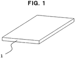
- Fig. 1 is a schematic perspective view of a reinforcing fiber prepreg 1 according to an embodiment of the present invention.
- the reinforcing fiber prepreg 1 is composed of reinforcing fibers and a matrix resin.
- a reinforcing fiber prepreg 1 comparatively short in the depth direction when applied to an AFP apparatus, it is necessary to have a width that can be introduced into an AFP apparatus with respect to width, for example, 1. 5 inch width, 1 inch width, 1/2 inch width, 1/4 inch width, and 1/8 inch width can be exemplified.
- a certain length is required, and it may be wound in a spool or reel shape.
- reinforcing fibers although not particularly limited, for example, it is preferred to use carbon fibers, glass fibers, aramid fibers, Kevlar fibers or the like.
- forms of reinforcing fiber base materials for example, a woven fabric, a knitted fabric, a nonwoven fabric, a unidirectional reinforcing fiber base material and a non-crimp fabric can be exemplified.
- a low-adhesion reinforcing fiber prepreg 2 is composed of a low-adhesion part (low-adhesion region) 21 and an ordinary part 22.
- the low-adhesion part 21 is a low-adhesion region that has reduced adhesiveness by applying adhesiveness reduction treatment as compared with the ordinary part 22.
- the resin reaction rate of the low-adhesion part 21 is preferably 0.1% to 20%, more preferably 0.1% to 15%, with respect to the resin reaction rate of the ordinary part 22, for example.
- the resin reaction rate of the matrix resin composition means a resin reaction rate of a resin (for example, an epoxy resin) in a matrix resin composition contained in the low-adhesion part 21 of the low-adhesion reinforcing fiber prepreg 2.
- the resin reaction rate of the matrix resin composition can be calculated by measuring a calorific value for curing by differential scanning calorimetry (DSC). Concretely, it can be calculated from the calorific value for curing of the matrix resin composition (E0) and the calorific value for curing of the resin contained in the prepreg (E1) by the following equation.
- Resin reaction rate of matrix resin composition % E 0 ⁇ E 1 / E 0 ⁇ 100
- the prepreg becomes too rigid and cannot pass through a process in some cases.
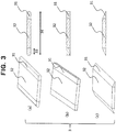
- the low-adhesion part 21 with respect to the existence position and shape of the low-adhesion part 21, it may be present at a part of the low-adhesion reinforcing fiber prepreg 2, and its concrete existence position and shape are not particularly limited.
- a shape in which the peripheral portions of the upper and lower surfaces of the low adhesion reinforcing fiber prepreg 2 are low-adhesion parts 21 can be exemplified.
- a shape in which the end surface of the low adhesion reinforcing fiber prepreg 2 is the low-adhesion part 21 can be exemplified.
- a shape in which the upper and lower surfaces of the low-adhesion reinforcing fiber prepreg 2 are the low-adhesion parts 21 can be exemplified.
- the contact portion between the cutting device and the reinforcing fiber prepreg becomes a low-adhesion part, which can improve the conveyance of the reinforcing fiber prepreg.
- a shape of the low-adhesion part a dot shape, a stripe shape extending in the longitudinal direction, the lateral direction or the oblique direction, or the like can also be exemplified.
- An end portion shape changing reinforcing fiber prepreg 3 is composed of a shape-changed end portion 31 and an ordinary part 32.
- the shape of the end portion 31 is not particularly limited as long as the thickness is partially reduced with respect to the ordinary part 32.
- a shape in which the cross-sectional shape of the end portion is an ellipse can be exemplified.
- a shape in which the cross-sectional shape of the end portion is a ⁇ shape can be exemplified.
- a shape in which the cross-sectional shape of the end portion is a ⁇ shape can be exemplified.
- a cross-sectional area of both end portions each occupying a region (the width 33 of the end portion) entered from each end by 10% of a maximum width (the width 34 of the reinforcing fiber prepreg) in a cross section perpendicular to the longitudinal direction of the reinforcing fiber prepreg tape is less than 15% of the entire cross-sectional area of the cross section perpendicular to the longitudinal direction of the reinforcing fiber prepreg tape.
- the resin reaction rate of the end portion 31 is preferably 0.1% to 20%, more preferably 0.1% to 15%, with respect to the resin reaction rate of the ordinary part 32, for example.
- the adhesiveness reduction treatment does not limit mechanism and formation as long as it can reduce adhesiveness.
- at least one of heat treatment, plasma irradiation treatment, and UV irradiation treatment can be exemplified.
- the energy utilized for the treatment is preferably in the form of propagating in a space, and UV irradiation is particularly preferable from the viewpoint of easy energy control.
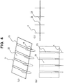
- Fig. 4 shows an embodiment of a method for producing a reinforcing fiber prepreg tape in which a low adhesion reinforcing fiber prepreg 2 is cut by a slitter 4 (slit blade) along its low-adhesion part 21, and shows (a) a schematic perspective view, (b) a schematic plan view, and (c) a schematic front sectional view, respectively.
- the slitter 4 is not limited with the configuration of the cutting mechanism and the slitter 4 as long as it can slit along the low-adhesion part 21 of the low-adhesion reinforcing fiber prepreg 2.
- a shear cutter or a score cutter can be exemplified.
- Fig. 5 shows an embodiment of a wound body 5 of a reinforcing fiber prepreg in which a part of the reinforcing fiber prepreg is a low-adhesion region to which an adhesiveness reduction treatment has been applied, and shows (a) a schematic perspective view, and (b) a schematic elevational view, respectively.
- the wound body 5 of the low-adhesion reinforcing fiber prepreg is one made into a bobbin shape by winding the low-adhesion reinforcing fiber prepreg 2 described above. It is a configuration in which the low-adhesion reinforcing fiber prepreg 2 is subsequently wound directly onto an outer layer of the low-adhesion reinforcing fiber prepreg 2 which has been wound previously.
- the reinforcing fiber prepreg 1 is prepared.
- adhesiveness reduction treatment is performed with respect to the region through which the slitter 4 passes.
- the shape of the shield for example, by providing a plurality of holes, it is possible to perform a low adhesiveness treatment in a spot shape, or a low adhesiveness treatment in a stripe shape can be performed by providing a slit.
- the resin of the reinforcing fiber prepreg 1 softens by a high temperature and the adhesiveness temporarily increases, and therefore, in case of a high-temperature reinforcing fiber prepreg 1, a way, wherein the reinforcing fiber prepreg 1 and the cutting device do not make physical contact, is desired. In case where the physical contact is inevitable, it is desirable to cool the reinforcing fiber prepreg 1 until the adhesiveness decreases before contact with the cutting device. Further, as the adhesiveness reduction treatment, at least one of heat treatment, plasma irradiation treatment, and UV irradiation treatment can be exemplified. By controlling the treatment time and treatment energy, it is possible to control the shape and thickness of the adhesiveness reduction treatment region in the thickness direction of the reinforcing fiber prepreg 1.
- the low-adhesion part 21 of the low-adhesion reinforcing fiber prepreg 2 having been subjected to the adhesiveness reduction treatment is cut so as to pass through the slitter 4.
- a blade for shear cutting or a blade for score cutting can be used as the kind of blade used for cutting.
- a prepreg "T800H/3900-2" supplied by Toray Industries, Inc. (reinforcing fiber: carbon fiber, thermosetting matrix resin: epoxy resin) was prepared.
- This prepreg had an areal weight of carbon fibers (CF) of 190 g/m 2 and a resin content of 35.5% by weight.
- the average single fiber diameter of the carbon fiber T800H-12K is 5 ⁇ m, and the tensile strength is 560 kgf/mm 2 .
- this material is merely an example of a preferred embodiment of the present invention, and the present invention is not limited to these materials.
- the matrix resin composition contained in the semi-cured prepregs obtained in Examples 1 to 3 or Comparative Example 2 described later was referred to as a semi-cured resin and the residual calorific value (E1) of this semi-cured resin and the calorific value for curing (E0) of the uncured matrix resin composition were measured using a DSC Q 2000 manufactured by TA Instrument Corporation under conditions of a temperature elevation rate of 5°C/min and a temperature range of -70°C to 300°C.
- Each of the reinforcing fiber prepregs described in Examples and Comparative Examples described later was placed at a stationary condition onto a metal plate at a room temperature, and pressed from the above thereof for 1 second so as to become 0.05 MPa. Thereafter, if the metal plate and the reinforcing fiber prepreg were adhered, it was determined to be "x", and if not adhered, it was determined to be "O".
- Each of the reinforcing fiber prepregs shown in Examples and Comparative Examples described later was cut out to obtain a sample having a length of 100 mm and a width of 15 mm.
- the sample was bent, one capable of having achieved an end-to-end distance of 40 mm was determined to be " ⁇ ", and one having broken halfway was determined to be "x".
- Example 1 a reinforcing fiber prepreg with a resin reaction rate of 0.1% was used.
- As the method for adhesiveness reduction treatment heat treatment was used. A test piece (15 mm in width and 300 mm in length) was placed in an oven at 60°C, and the resin was reacted until the resin reaction rate became 0.1%. It was placed at a stationary condition onto a metal plate at a room temperature, and then pressed from the above thereof for 1 second so as to become 0.05 MPa. Thereafter, when observing the metal plate and the reinforcing fiber prepreg, they did not adhere. Subsequently, the reinforcing fiber prepreg was cut out to obtain a sample having a length of 100 mm and a width of 15 mm. When the sample was bent, the distance between the end portions could be made 40 mm.
- Example 2 a reinforcing fiber prepreg with a resin reaction rate of 7.3% was used.
- the method for adhesiveness reduction treatment heat treatment was used.
- a test piece (15 mm in width and 300 mm in length) was placed in an oven at 60°C, and the resin was reacted until the resin reaction rate became 7.3%. It was placed at a stationary condition onto a metal plate at a room temperature, and then pressed from the above thereof for 1 second so as to become 0.05 MPa. Thereafter, when observing the metal plate and the reinforcing fiber prepreg, they did not adhere. Subsequently, the reinforcing fiber prepreg was cut out to obtain a sample having a length of 100 mm and a width of 15 mm. When the sample was bent, the distance between the end portions could be made 40 mm.
- Example 3 a reinforcing fiber prepreg with a resin reaction rate of 14.5% was used.
- heat treatment was used.
- a test piece (15 mm in width and 300 mm in length) was placed in an oven at 60°C, and the resin was reacted until the resin reaction rate became 14.5%. It was placed at a stationary condition onto a metal plate at a room temperature, and then pressed from the above thereof for 1 second so as to become 0.05 MPa. Thereafter, when observing the metal plate and the reinforcing fiber prepreg, they did not adhere. Subsequently, the reinforcing fiber prepreg was cut out to obtain a sample having a length of 100 mm and a width of 15 mm. When the sample was bent, the distance between the end portions could be made 40 mm.
- Comparative Example 1 a reinforcing fiber prepreg which was uncured and had a resin reaction rate of 0% was used. It was placed at a stationary condition onto a metal plate at a room temperature, and then pressed from the above thereof for 1 second so as to become 0.05 MPa. Thereafter, when observing the metal plate and the reinforcing fiber prepreg, they adhered to each other. Subsequently, the reinforcing fiber prepreg was cut out to obtain a sample having a length of 100 mm and a width of 15 mm. When the sample was bent, it was possible to make the distance between the end portions could be made 40 mm.
- a reinforcing fiber prepreg with a resin reaction rate of 28.2% was used.
- heat treatment was used.
- a test piece (15 mm in width and 300 mm in length) was placed in an oven at 60°C, and the resin was reacted until the resin reaction rate became 28.2%. It was placed at a stationary condition onto a metal plate at a room temperature, and then pressed from the above thereof for 1 second so as to become 0.05 MPa. Thereafter, when observing the metal plate and the reinforcing fiber prepreg, they did not adhere. Subsequently, the reinforcing fiber prepreg was cut out to obtain a sample having a length of 100 mm and a width of 15 mm. When the sample was bent, the distance between the end portions could not be made 40 mm.
- Table 1 shows the resin reaction rates and evaluation results of Examples 1 to 3 and Comparative Examples 1 and 2.
- Table 1 Resin reaction rate (%) Evaluation of adhesiveness Evaluation of bendability Comparative Example 1 0 ⁇ ⁇ Example 1 0.1 ⁇ ⁇ Example 2 7.3 ⁇ ⁇ Example 3 14.5 ⁇ ⁇ Comparative Example 2 28.2 ⁇ ⁇
- the conveyance process of AFP is facilitated, and this low-adhesion reinforcing fiber prepreg can be suitably applied to AFP (Automatic Fiber Placement) used in the aircraft industry and the automobile industry.
- AFP Automatic Fiber Placement
Landscapes
- Chemical & Material Sciences (AREA)
- Materials Engineering (AREA)
- Engineering & Computer Science (AREA)
- Chemical Kinetics & Catalysis (AREA)
- Medicinal Chemistry (AREA)
- Polymers & Plastics (AREA)
- Organic Chemistry (AREA)
- Health & Medical Sciences (AREA)
- Manufacturing & Machinery (AREA)
- Inorganic Chemistry (AREA)
- Reinforced Plastic Materials (AREA)
- Moulding By Coating Moulds (AREA)
- Chemical Or Physical Treatment Of Fibers (AREA)
Applications Claiming Priority (3)
| Application Number | Priority Date | Filing Date | Title |
|---|---|---|---|
| JP2016243034 | 2016-12-15 | ||
| JP2016243033 | 2016-12-15 | ||
| PCT/JP2017/043949 WO2018110404A1 (ja) | 2016-12-15 | 2017-12-07 | 強化繊維プリプレグ、強化繊維プリプレグのテープおよび巻取体、ならびに強化繊維プリプレグおよび強化繊維プリプレグテープの製造方法 |
Publications (2)
| Publication Number | Publication Date |
|---|---|
| EP3556800A1 true EP3556800A1 (de) | 2019-10-23 |
| EP3556800A4 EP3556800A4 (de) | 2020-08-19 |
Family
ID=62558459
Family Applications (1)
| Application Number | Title | Priority Date | Filing Date |
|---|---|---|---|
| EP17881785.4A Withdrawn EP3556800A4 (de) | 2016-12-15 | 2017-12-07 | Faserverstärktes prepreg, band und gewundener körper aus faserverstärktem prepreg und verfahren zur herstellung von faserverstärktem prepreg und faserverstärktem prepreg-band |
Country Status (8)
| Country | Link |
|---|---|
| US (1) | US20200231771A1 (de) |
| EP (1) | EP3556800A4 (de) |
| JP (1) | JP6922746B2 (de) |
| CN (1) | CN110072924A (de) |
| BR (1) | BR112019010975A2 (de) |
| CA (1) | CA3046427A1 (de) |
| RU (1) | RU2019121672A (de) |
| WO (1) | WO2018110404A1 (de) |
Families Citing this family (3)
| Publication number | Priority date | Publication date | Assignee | Title |
|---|---|---|---|---|
| JPWO2020067478A1 (ja) * | 2018-09-27 | 2021-08-30 | 三菱ケミカル株式会社 | テーププリプレグ、テーププリプレグの配置方法、繊維強化複合材料及び繊維強化複合材料の製造方法 |
| JP2021126847A (ja) * | 2020-02-14 | 2021-09-02 | 東レ株式会社 | 強化繊維プリプレグテープおよびそれを用いた巻取体 |
| JP7819447B2 (ja) * | 2021-06-16 | 2026-02-25 | 住友ゴム工業株式会社 | 中空frp成形品及びその製造方法 |
Family Cites Families (19)
| Publication number | Priority date | Publication date | Assignee | Title |
|---|---|---|---|---|
| JPS61160230A (ja) * | 1985-01-10 | 1986-07-19 | Matsushita Electric Works Ltd | 積層板の製造方法 |
| JP2903556B2 (ja) * | 1989-09-07 | 1999-06-07 | 三菱瓦斯化学株式会社 | ガラス基材プリプレグの処理法 |
| JPH0462051A (ja) * | 1990-06-26 | 1992-02-27 | Sumitomo Bakelite Co Ltd | 積層板の製造方法 |
| JP2636594B2 (ja) * | 1990-12-26 | 1997-07-30 | 新神戸電機株式会社 | 金属箔張り積層板の製造法 |
| JPH07171830A (ja) * | 1991-06-05 | 1995-07-11 | Mitsubishi Gas Chem Co Inc | ガラス基材プリプレグの処理装置及びその処理法 |
| JP2514541Y2 (ja) * | 1991-10-30 | 1996-10-23 | 新神戸電機株式会社 | プリプレグ端面熱処理装置 |
| JPH05245836A (ja) * | 1992-03-04 | 1993-09-24 | Shimano Inc | プリプレグ |
| JPH05269738A (ja) * | 1992-03-24 | 1993-10-19 | Sumitomo Bakelite Co Ltd | 積層板の製造方法 |
| JP3632177B2 (ja) * | 2002-11-29 | 2005-03-23 | 川崎重工業株式会社 | プリプレグ幅変更自動積層方法及びその装置 |
| US20060043628A1 (en) * | 2004-08-11 | 2006-03-02 | General Electric Company | CMC process using a water-based prepreg slurry |
| JP4727525B2 (ja) | 2006-07-28 | 2011-07-20 | 三菱重工業株式会社 | 冷却装置を備えた繊維強化プラスチックの積層成形装置 |
| JP5301387B2 (ja) * | 2009-08-06 | 2013-09-25 | 新明和工業株式会社 | プリプレグテープの切断方法及びスリッタ装置 |
| TWI492982B (zh) * | 2012-09-06 | 2015-07-21 | Mitsubishi Rayon Co | 預浸體及其製造方法 |
| EP3031860B1 (de) * | 2013-08-07 | 2019-09-25 | Toray Industries, Inc. | Epoxidharzzusammensetzung-basiertes prepreg und faserverstärktes verbundmaterial |
| US20150151486A1 (en) * | 2013-12-03 | 2015-06-04 | Ford Global Technologies, Llc | System and process for producing a composite article |
| WO2015191354A1 (en) * | 2014-06-09 | 2015-12-17 | Dow Global Technologies Llc | Process for making curable, multi-layer fiber-reinforced prepreg |
| JP2016043580A (ja) * | 2014-08-22 | 2016-04-04 | トヨタ自動車株式会社 | 積層基板の製造方法 |
| JP2016155915A (ja) * | 2015-02-24 | 2016-09-01 | 三菱レイヨン株式会社 | 繊維強化プラスチック線材及びその製造方法、並びに繊維強化プラスチック線材の製造システム |
| KR20180066107A (ko) * | 2015-10-13 | 2018-06-18 | 다우 글로벌 테크놀로지스 엘엘씨 | 고처리량 제조 공정에서 사용하기 위한 속경화 에폭시 조성물 |
-
2017
- 2017-12-07 CN CN201780076494.3A patent/CN110072924A/zh active Pending
- 2017-12-07 RU RU2019121672A patent/RU2019121672A/ru not_active Application Discontinuation
- 2017-12-07 US US16/468,887 patent/US20200231771A1/en not_active Abandoned
- 2017-12-07 CA CA3046427A patent/CA3046427A1/en not_active Abandoned
- 2017-12-07 JP JP2017567829A patent/JP6922746B2/ja active Active
- 2017-12-07 BR BR112019010975A patent/BR112019010975A2/pt not_active Application Discontinuation
- 2017-12-07 EP EP17881785.4A patent/EP3556800A4/de not_active Withdrawn
- 2017-12-07 WO PCT/JP2017/043949 patent/WO2018110404A1/ja not_active Ceased
Also Published As
| Publication number | Publication date |
|---|---|
| EP3556800A4 (de) | 2020-08-19 |
| WO2018110404A1 (ja) | 2018-06-21 |
| JPWO2018110404A1 (ja) | 2019-10-24 |
| JP6922746B2 (ja) | 2021-08-18 |
| CN110072924A (zh) | 2019-07-30 |
| US20200231771A1 (en) | 2020-07-23 |
| CA3046427A1 (en) | 2018-06-21 |
| RU2019121672A (ru) | 2021-01-15 |
| RU2019121672A3 (de) | 2021-03-25 |
| BR112019010975A2 (pt) | 2019-10-15 |
Similar Documents
| Publication | Publication Date | Title |
|---|---|---|
| EP3061785B1 (de) | Verfahren zur herstellung von prepregs | |
| EP3604409B1 (de) | Prepreg-folie, verfahren zur herstellung davon, mit hautmaterial versehene unitäre schicht, verfahren zur herstellung eines aus faserverstärktem verbundstoffmaterial geformten artikels und aus faserverstärktem verbundstoffmaterial geformter artikel | |
| JP6250393B2 (ja) | 改善された複合材料 | |
| JP5353099B2 (ja) | 繊維強化プラスチックの製造方法 | |
| EP3556800A1 (de) | Faserverstärktes prepreg, band und gewundener körper aus faserverstärktem prepreg und verfahren zur herstellung von faserverstärktem prepreg und faserverstärktem prepreg-band | |
| US11597168B2 (en) | Thin-layer tape automated lamination method and device | |
| KR102337938B1 (ko) | 시트 몰딩 컴파운드 | |
| EP3045489A1 (de) | Thermoplastisches prepreg und laminat | |
| KR102434377B1 (ko) | 도포액 함침 시트형 강화 섬유 다발 및 시트형 일체물의 제조 방법, 도포 장치 | |
| EP2822758B1 (de) | Verbundstoff für automatisierte auflage | |
| CN108368282A (zh) | 预浸带及其利用 | |
| CN112566765B (zh) | 预浸料坯的制造方法及制造装置 | |
| EP3715403A1 (de) | Verfahren und vorrichtung zur herstellung von faserverstärktem harzformmaterial | |
| EP3835342A1 (de) | Verfahren zur herstellung eines prepregs, beschichtungsvorrichtung und vorrichtung zur herstellung eines prepregs | |
| KR102871842B1 (ko) | 복합 시트의 성형 방법 및 성형 장치 | |
| JP2010023359A (ja) | 積層体の製造方法 | |
| CN111674060A (zh) | 碳纤维束的分纤方法 | |
| JP2018176709A (ja) | トウプリプレグの製造装置及びその製造方法 | |
| EP3842202B1 (de) | Herstellungsverfahren für prepreg, prepreg-band sowie faserverstärkter verbundstoff und vorrichtung zur herstellung von prepreg | |
| EP4416208A1 (de) | Prepreg-bandschlitzvorrichtung und -verfahren | |
| US20180339471A1 (en) | Slitting | |
| EP3252093A1 (de) | Faserverstärkter verbundstoff | |
| CN111890702A (zh) | 一种利用热塑性连续纤维带编制成板材的方法 | |
| KR20190033685A (ko) | 프리프레그를 이용한 장섬유 강화 시트 제조 장치 |
Legal Events
| Date | Code | Title | Description |
|---|---|---|---|
| STAA | Information on the status of an ep patent application or granted ep patent |
Free format text: STATUS: THE INTERNATIONAL PUBLICATION HAS BEEN MADE |
|
| PUAI | Public reference made under article 153(3) epc to a published international application that has entered the european phase |
Free format text: ORIGINAL CODE: 0009012 |
|
| STAA | Information on the status of an ep patent application or granted ep patent |
Free format text: STATUS: REQUEST FOR EXAMINATION WAS MADE |
|
| 17P | Request for examination filed |
Effective date: 20190604 |
|
| AK | Designated contracting states |
Kind code of ref document: A1 Designated state(s): AL AT BE BG CH CY CZ DE DK EE ES FI FR GB GR HR HU IE IS IT LI LT LU LV MC MK MT NL NO PL PT RO RS SE SI SK SM TR |
|
| AX | Request for extension of the european patent |
Extension state: BA ME |
|
| DAV | Request for validation of the european patent (deleted) | ||
| DAX | Request for extension of the european patent (deleted) | ||
| RIC1 | Information provided on ipc code assigned before grant |
Ipc: C08J 5/04 20060101ALI20200709BHEP Ipc: C08J 5/24 20060101AFI20200709BHEP |
|
| A4 | Supplementary search report drawn up and despatched |
Effective date: 20200717 |
|
| RIC1 | Information provided on ipc code assigned before grant |
Ipc: C08J 5/04 20060101ALI20200710BHEP Ipc: C08J 5/24 20060101AFI20200710BHEP |
|
| STAA | Information on the status of an ep patent application or granted ep patent |
Free format text: STATUS: THE APPLICATION HAS BEEN WITHDRAWN |
|
| 18W | Application withdrawn |
Effective date: 20210708 |