EP3556922A1 - Dispositif de traitement thermique d'une bande de matière textile - Google Patents
Dispositif de traitement thermique d'une bande de matière textile Download PDFInfo
- Publication number
- EP3556922A1 EP3556922A1 EP19165679.2A EP19165679A EP3556922A1 EP 3556922 A1 EP3556922 A1 EP 3556922A1 EP 19165679 A EP19165679 A EP 19165679A EP 3556922 A1 EP3556922 A1 EP 3556922A1
- Authority
- EP
- European Patent Office
- Prior art keywords
- drum
- band
- longitudinal edge
- web
- belt
- Prior art date
- Legal status (The legal status is an assumption and is not a legal conclusion. Google has not performed a legal analysis and makes no representation as to the accuracy of the status listed.)
- Granted
Links
Images


Classifications
-
- D—TEXTILES; PAPER
- D04—BRAIDING; LACE-MAKING; KNITTING; TRIMMINGS; NON-WOVEN FABRICS
- D04H—MAKING TEXTILE FABRICS, e.g. FROM FIBRES OR FILAMENTARY MATERIAL; FABRICS MADE BY SUCH PROCESSES OR APPARATUS, e.g. FELTS, NON-WOVEN FABRICS; COTTON-WOOL; WADDING ; NON-WOVEN FABRICS FROM STAPLE FIBRES, FILAMENTS OR YARNS, BONDED WITH AT LEAST ONE WEB-LIKE MATERIAL DURING THEIR CONSOLIDATION
- D04H1/00—Non-woven fabrics formed wholly or mainly of staple fibres or like relatively short fibres
- D04H1/40—Non-woven fabrics formed wholly or mainly of staple fibres or like relatively short fibres from fleeces or layers composed of fibres without existing or potential cohesive properties
- D04H1/54—Non-woven fabrics formed wholly or mainly of staple fibres or like relatively short fibres from fleeces or layers composed of fibres without existing or potential cohesive properties by welding together the fibres, e.g. by partially melting or dissolving
- D04H1/5405—Non-woven fabrics formed wholly or mainly of staple fibres or like relatively short fibres from fleeces or layers composed of fibres without existing or potential cohesive properties by welding together the fibres, e.g. by partially melting or dissolving at spaced points or locations
-
- D—TEXTILES; PAPER
- D06—TREATMENT OF TEXTILES OR THE LIKE; LAUNDERING; FLEXIBLE MATERIALS NOT OTHERWISE PROVIDED FOR
- D06B—TREATING TEXTILE MATERIALS USING LIQUIDS, GASES OR VAPOURS
- D06B5/00—Forcing liquids, gases or vapours through textile materials to effect treatment, e.g. washing, dyeing, bleaching, sizing impregnating
- D06B5/02—Forcing liquids, gases or vapours through textile materials to effect treatment, e.g. washing, dyeing, bleaching, sizing impregnating through moving materials of indefinite length
- D06B5/08—Forcing liquids, gases or vapours through textile materials to effect treatment, e.g. washing, dyeing, bleaching, sizing impregnating through moving materials of indefinite length through fabrics
-
- D—TEXTILES; PAPER
- D06—TREATMENT OF TEXTILES OR THE LIKE; LAUNDERING; FLEXIBLE MATERIALS NOT OTHERWISE PROVIDED FOR
- D06C—FINISHING, DRESSING, TENTERING OR STRETCHING TEXTILE FABRICS
- D06C23/00—Making patterns or designs on fabrics
-
- D—TEXTILES; PAPER
- D06—TREATMENT OF TEXTILES OR THE LIKE; LAUNDERING; FLEXIBLE MATERIALS NOT OTHERWISE PROVIDED FOR
- D06C—FINISHING, DRESSING, TENTERING OR STRETCHING TEXTILE FABRICS
- D06C7/00—Heating or cooling textile fabrics
-
- F—MECHANICAL ENGINEERING; LIGHTING; HEATING; WEAPONS; BLASTING
- F26—DRYING
- F26B—DRYING SOLID MATERIALS OR OBJECTS BY REMOVING LIQUID THEREFROM
- F26B13/00—Machines and apparatus for drying fabrics, fibres, yarns, or other materials in long lengths, with progressive movement
- F26B13/10—Arrangements for feeding, heating or supporting materials; Controlling movement, tension or position of materials
- F26B13/12—Controlling movement, tension or position of material
-
- F—MECHANICAL ENGINEERING; LIGHTING; HEATING; WEAPONS; BLASTING
- F26—DRYING
- F26B—DRYING SOLID MATERIALS OR OBJECTS BY REMOVING LIQUID THEREFROM
- F26B13/00—Machines and apparatus for drying fabrics, fibres, yarns, or other materials in long lengths, with progressive movement
- F26B13/10—Arrangements for feeding, heating or supporting materials; Controlling movement, tension or position of materials
- F26B13/14—Rollers, drums, cylinders; Arrangement of drives, supports, bearings, cleaning
- F26B13/16—Rollers, drums, cylinders; Arrangement of drives, supports, bearings, cleaning perforated in combination with hot air blowing or suction devices, e.g. sieve drum dryers
Definitions
- the present invention relates to a device for the thermal treatment of a textile web, in particular dryer or thermal bonder, comprising at least one drum with a perforated lateral surface whose shell is at least partially wrapped by a web, wherein on the shell of the drum, a structural shell is windable, the one Has a variety of openings and / or patterns.
- the thermal treatment of a textile web of nonwoven or nonwoven fabric includes hot air drying or hot air solidification in a flow-through, in which a heated gas, such as air, flows through the web and thereby dried or solidified.
- a heated gas such as air
- dryer or thermal bonders are known in which one or more drums are arranged in a housing. Through an opening in the dryer chamber, a textile web is fed to the dryer by wrapping the drum to a large extent of the circumference and then guided around the next drum and / or discharged from the dryer chamber again.
- the web is treated, in which either fresh air blown through the web and the drum and absorbs the moisture from the web, or due to the hot air or the hot gas, a thermal Solidification of the web occurs because their fibers, for example made of polyamide, at least partially merge with each other, or a treatment of the web takes place with hot steam.
- a smooth unstructured nonwoven fabric is produced, which can be used, for example, as topsheets for panty liners.
- the metallic structure shell on the drum must be changed.
- the height of the structuring in the nonwoven depends on the thickness of the shell surface of the structural shell.
- the change of the structural shells is very complicated, since the entire structural shell is to be taken along the longitudinal axis of the drum.
- the structural shell can have a diameter of up to 4 m and a length of up to 4.5. This is very time-consuming and labor-intensive and the Thermobonder is due to the conversion measure a longer time not available because parts of the housing if necessary. Must be removed.
- the structural shell consists of a metallic, relatively stiff cylinder jacket, which is pushed over the drum.
- the object of the invention is the development of a device for the thermal treatment of a textile web, comprising at least one drum with a perforated lateral surface whose shell is at least partially wrapped by a web.
- the replacement of the structural shell is to be simplified and done in no time.
- the invention relates to a device for the thermal treatment of a textile material web, in particular dryer or thermal bonder, comprising at least one drum with a perforated lateral surface whose shell is at least partially wrapped by a web, wherein on the shell of the drum, a structural shell is windable, the plurality of openings and / or patterns.
- the invention is characterized in that the structural shell is formed as a band of limited width, which is wound around the drum with a plurality of turns.
- a conventional structural shell which can have a diameter of up to 4 m and a width of up to 4.5 as a cylindrical thin hollow body, a long band of limited width is less expensive to produce than endless material.
- the assembly of the structural shell can be done as a tape without disassembly of the drum housing, whereby production changes without longer downtime are possible.
- the band has a first and a second longitudinal edge, which touch each other or overlap with each wrap around the drum. This creates a closed surface in which adjacent longitudinal edges are not reflected in the web.
- a preferred embodiment provides that the band has a limited length, and the beginning and the end of the band with at least one attachment point to the drum can be fastened. This results in no overlap of the band, as in an endless belt.
- the band has a width of 5 cm to 30 cm. This allows the tape to be wound onto a roll and is so manageable in weight and dimensions that it can be used as a single piece Installer can raise this with a jig alone on the drum.
- the width of the band in this area allows high flexibility for drums of different diameters and widths.
- the first with the second longitudinal edge at least in sections releasably or permanently connected.
- This can be done by stitching, welding or by stitching, with a continuous attachment along the entire longitudinal edge is possible, but not necessary.
- Sufficient may be a regular attachment, which is repeated in short sections offset from the adjacent longitudinal edges, for example, three to four times on the circumference of the drum.
- the device for the thermal treatment of the web may comprise a tensioning roller, which is wrapped by the belt simultaneously with the drum, wherein the distance to the drum is adjustable.
- the band can be mounted without great effort, the longitudinal edges are aligned with each other and then the tension roller to clamp the structural shell are operated.
- the tape can be shrunk onto the drum, in which case the tape can only be removed destructively from the drum.
- a wire is arranged on or in at least one longitudinal edge of the strip, which extends without interruption over the entire length of the strip. This prevents overstretching of the band during assembly and at the same time prevents bulging of the longitudinal edge.
- both longitudinal edges of the band have a reduced thickness, which complement each other in an overlapping arrangement complete a full cross section.
- the geometry of the reduced thickness may be arbitrary, for example wedge-shaped or in the form of a remote step or step. Since the drum and the belt stretch during operation of the thermal belt, an enlargement of the gaps at the longitudinal edges can be counteracted hereby. Clogging of the gaps or adhesion of the fibers to this gap can thus be reduced.
- a shoulder or a wedge-shaped reduction of the cross section may be arranged at the top of the belt, and arranged on the second longitudinal edge of the complementary shoulder or wedge on the underside of the belt, or vice versa.
- a fastening element in the overlapping region of the longitudinal edges, can be arranged or integrated at regular intervals, with which the longitudinal edges can be fastened to one another.
- first longitudinal edge can also be positively connected to the second longitudinal edge, so that here a zipper effect can be used for assembly and disassembly.
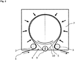
- Fig. 1 shows a hot air dryer or thermobonder in omega construction according to the prior art.
- the material to be dried web 1 runs in the inlet region 4 via a deflection drum 2 in the dryer, wraps around the air-permeable designed drum 5 in a clockwise direction and runs over a further deflection drum 3 from the dryer again.
- the web 1 may consist of a pre-consolidated web of fibers or filaments. Often the web 1 is a coming from a card pile from loose staple fibers. The pile can be transported on a conveyor belt from the card to the drum 5.
- the tail pulley 2 can be designed as a suction drum and transports the loose pile to the drum 5 of the dryer or thermobonder.
- the deflection drum 3 can also be designed as a suction drum in order to cool the thermally bonded nonwoven or the dried material web with ambient air again.
- the drum 5, and the two deflection drums 2, 3 are arranged in a housing 7, in which hot air is introduced via means not shown.
- the hot air flows through the web 1, dries this or heats the web 1 to the melting temperature of the binder fiber or other bicomponent fibers, and is sucked off by a in the drum 5 the front side, not shown fan.
- the drum 5 is placed under negative pressure, so that different flow conditions occur in the dryer.
- a structural shell 10 is mounted on the drum 5, which may contain a plurality of openings or patterns.
- the structural shell 10 usually consists of a fine sheet in which the pattern was lasered. Alternatively, there are also wire mesh with a corresponding pattern. These structural shells are pushed as a thin hollow cylindrical body along the longitudinal axis of the drum 5. With a width of the web of 2.5 to 5.5 m, often a part of the dryer housing must be dismantled, which is associated with longer downtime.
- the structural shell 10 is designed as a flexible element of a thermally resilient material, which is guided around the drum 5, led out of the housing 7 of the dryer or Thermobonders and deflected by a deflection roller 3.
- This structural shell 10 is made in one piece and consists of a band 11 which is wound around the drum 5 in many turns.
- the structural shell 10 can be stretched or relaxed, which greatly facilitates the replacement of the structural shell 10.
- this structural shell 10 has a plurality of openings or patterns, so that the web 1, which leaves the dryer or Thermobonder has a perforated or patterned surface. Depending on the configuration of the system in connection with the fiber composition of the web 1, the pattern may relate to only one surface of the web 1, or both surfaces.
- the structural shell 10 consists of a band 11 of limited width, wound in many turns around the drum 5, the longitudinal edges 11a, 11b of the band 11 either touching or overlapping.
- the advantage lies in the ease of installation, since the dryer housing does not have to be dismantled for this purpose.
- At the beginning or end of the assembly process arise one or two seams or attachment points 12, with which the tape 11 is attached to itself in the form of an endless belt or on the drum 5.
- this interface or the attachment points 12 is not reflected in the web 1, the drum 5 has a greater width TB, as the working width AB of the plant or the width of the web. 1
- the band 11 is preferably between 5 to 30 cm wide and can be stored rolled up on a roll and provided for mounting. With a drum width of 5 m results between 100 and 17 turns, whereby the working width then between 4.9 m to 4.4 m can lie.
- a metal in the form of a wire mesh, or a glass cloth tape for example made of PTFE or a heat-resistant plastic can be used.
- textile bands 11 are possible.
- the bands 11 may have a raised patterned surface which impress like a watermark in the web 1 and reduce the thickness of the web 1 at this point.
- the pattern 13 may be embedded or integrated in the band 11 in the form of apertures, at which points there is a thickening or concentration of fibers which are not fully bonded.
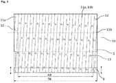
- FIG. 3 shows an embodiment with an adjustable tension roller 9, with the band 11 can be tightened after wrapping the drum 5.
- the band 11 is attached to the drum 5 with two attachment points 12.
- the usable working width AB is smaller than the available drum width TB.
- the tension on the belt 11 is generated by the adjustability of the tension roller 9.
- the patterning of the belt 11 may be regular or irregular.
- the first longitudinal edge 11a rests after a winding of the drum 5 at the second longitudinal edge 11b.
- FIG. 4 shows another embodiment with a band 11 as patterning structural shell 10 which has been wound in turns around the drum 5.
- the band 11 is attached to the drum 5 with two attachment points 12, so that the usable working width AB is smaller than the available drum width TB.
- the first longitudinal edge 11a abuts against the second longitudinal edge 11b.
- a band 11 of a slightly shrinking material for example, a film may be used, which is held on the drum 5 due to its shrinkage stress.
- This tape 11 is to be used as a one-time solution and can only destructively removed from the drum 5.
- the band 11 can also be made removable by making the attachment points 12 detachable.
- FIGS. 5 and 5a show a woven belt 11 with a printed pattern 13 in the form of hemispheres, which press in the thermobonding as a depression in the web 1.
- the woven tape 11 may be made of a heat-resistant textile, or be formed of a metallic material.
- At least one longitudinal edge 11a of the band 11 can be reinforced with an integrated wire 16 so that bulging can be avoided.
- both longitudinal edges 11a, 11b of the band 11 can be reinforced with a wire 16.
- the wire 16 also has the function of preventing elongation during operation.
- the volume 11 after the Figures 6 and 6a can be made of a heat-resistant plastic and has a plurality of regular or irregular patterns 13 in the form of squares, which penetrate into the band 11 at least partially or completely penetrate. Between the patterns 13 may be arranged in a regular or irregular arrangement, a plurality of openings 14 which are formed for example as micro-openings and penetrate the belt 11. By the pattern 13, which penetrate the band 11 in this embodiment, results for the web 1 a nub structure with raised points or areas. With the micro-openings, the surface structure of the web 1 can be influenced, since at least partially the fibers penetrate into the openings 14 and thus the surface of the web 1 is more structured and rougher. The feel of the web 1 is rougher. Also the band 11 according to this embodiment may be reinforced at one or both longitudinal edges 11a, 11b with a wire 16, which is preferably integrated in the band 11.
- FIG. 7 shows two adjacent bands 11, which overlap in the edge region.
- each band 11 has along a first longitudinal edge 11a a first shoulder 11c on its upper side, and along its second longitudinal edge 11b has a second shoulder 11c on its underside.
- the longitudinal edges 11a, 11b may thus have a reduced thickness, which complement each other in a juxtaposed bands 11 to a full cross-section.
- the paragraphs 11c are arranged so complementary to each other that a partial overlap arises, so that the top and bottom of the adjacent bands 11 acts on the web 1 substantially without interruption with a closed and flat surface.
- the adjacent bands 11 can be fastened to one another, for example by means of a fastening element 15 in the form of a pin, or a clip (not shown).
- the fastener 15 as a pin may be part of a belt 11, and for example fixedly attached to a longitudinal edge 11a, 11b or be integrally attached thereto.
- the associated opening can then be integrated at the other longitudinal edge 11a, 11b in the remaining cross-section already in the pin spacings, or be produced during assembly.
- the tapes 11 can also be fastened together at points at least at regular intervals by means of sewing, stapling, fusing or welding. An uninterrupted connection is usually unnecessary. A connection by means of plug seam is possible.
- the necessary tension on the belt 11 can then according to the embodiment of the Figures 2 and 3 through the tension roller 9 be applied, or according to the embodiment of FIG. 4 by a thermal shrinkage.
- the wire 16 is integrated in a longitudinal edge 11a of the belt 11 and thus causes an increased investment of this longitudinal edge 11a of the belt 11 on the drum fifth
- the longitudinal edges 11a, 11b of the band 11 can also be designed such that, for example, rectangular or round projections engage in rectangular or round openings and the bands are thus positively connected to the longitudinal edges 11a, 11b, similar to a zipper.
- the patterns 13 can be integrated into the positive locking of the longitudinal edges 11a, 11b. Since with each wrapping of the belt 11 to the drum 5 is not always the optimum extent is achieved, since the tape 11 is then either too tight or too loose, with the thermal stress compensation or the tension roller 9 compensation for perfect contact with the drum. 5 be generated.
Landscapes
- Engineering & Computer Science (AREA)
- Textile Engineering (AREA)
- Mechanical Engineering (AREA)
- General Engineering & Computer Science (AREA)
- Chemical & Material Sciences (AREA)
- Materials Engineering (AREA)
- Treatment Of Fiber Materials (AREA)
Priority Applications (1)
| Application Number | Priority Date | Filing Date | Title |
|---|---|---|---|
| PL19165679T PL3556922T3 (pl) | 2018-04-16 | 2019-03-28 | Urządzenie do termicznej obróbki tekstylnej wstęgi produktu |
Applications Claiming Priority (1)
| Application Number | Priority Date | Filing Date | Title |
|---|---|---|---|
| DE102018108944.9A DE102018108944A1 (de) | 2018-04-16 | 2018-04-16 | Vorrichtung zum thermischen Behandeln einer textilen Warenbahn |
Publications (2)
| Publication Number | Publication Date |
|---|---|
| EP3556922A1 true EP3556922A1 (fr) | 2019-10-23 |
| EP3556922B1 EP3556922B1 (fr) | 2020-08-19 |
Family
ID=65995625
Family Applications (1)
| Application Number | Title | Priority Date | Filing Date |
|---|---|---|---|
| EP19165679.2A Not-in-force EP3556922B1 (fr) | 2018-04-16 | 2019-03-28 | Dispositif de traitement thermique d'une bande de matière textile |
Country Status (4)
| Country | Link |
|---|---|
| EP (1) | EP3556922B1 (fr) |
| CN (1) | CN110388804B (fr) |
| DE (1) | DE102018108944A1 (fr) |
| PL (1) | PL3556922T3 (fr) |
Families Citing this family (1)
| Publication number | Priority date | Publication date | Assignee | Title |
|---|---|---|---|---|
| CN119665617B (zh) * | 2025-02-17 | 2025-06-17 | 安徽衡川新能源材料科技有限公司 | 一种锂电池隔膜生产加工用烘干装置 |
Citations (5)
| Publication number | Priority date | Publication date | Assignee | Title |
|---|---|---|---|---|
| DE2342421A1 (de) * | 1972-09-15 | 1974-03-21 | Improved Machinery Inc | Trommel mit gitterkonstruktion |
| EP0841424A1 (fr) * | 1996-11-11 | 1998-05-13 | Fleissner GmbH & Co. Maschinenfabrik | Dispositif pour l'aiguilletage hydraulique d'étoffes nont-tissées, tissus |
| WO1999018022A1 (fr) * | 1997-10-03 | 1999-04-15 | Minnesota Mining And Manufacturing Company | Revetements pour rouleaux facilement remplaçables |
| WO2005111304A1 (fr) * | 2004-05-07 | 2005-11-24 | Voith Patent Gmbh | Cylindre aspirant de machine pour produire une bande de matiere fibreuse |
| EP3159446A2 (fr) * | 2015-10-23 | 2017-04-26 | Trützschler GmbH & Co. KG | Dispositif de traitement thermique d'une nappe de tissu textile |
Family Cites Families (5)
| Publication number | Priority date | Publication date | Assignee | Title |
|---|---|---|---|---|
| DE10355732B4 (de) * | 2003-11-28 | 2007-11-29 | Karl Mayer Textilmaschinenfabrik Gmbh | Schärverfahren |
| ATE464420T1 (de) * | 2007-01-08 | 2010-04-15 | Electrolux Home Prod Corp | Sensorvorrichtung zur bestimmung der winkelposition einer waschtrommel einer waschmaschine |
| CN103806138A (zh) * | 2012-11-13 | 2014-05-21 | 湖北清河纺织股份有限公司 | 一种梳棉机清洁装置 |
| CN205774944U (zh) * | 2016-05-17 | 2016-12-07 | 吴江市新谊纺织品有限责任公司 | 纺织用蚕茧清洗装置 |
| CN206862063U (zh) * | 2017-05-13 | 2018-01-09 | 苏州布德机电设备有限公司 | 一种纺织原料烘干装置 |
-
2018
- 2018-04-16 DE DE102018108944.9A patent/DE102018108944A1/de not_active Withdrawn
-
2019
- 2019-03-28 EP EP19165679.2A patent/EP3556922B1/fr not_active Not-in-force
- 2019-03-28 PL PL19165679T patent/PL3556922T3/pl unknown
- 2019-04-12 CN CN201910296930.9A patent/CN110388804B/zh not_active Expired - Fee Related
Patent Citations (5)
| Publication number | Priority date | Publication date | Assignee | Title |
|---|---|---|---|---|
| DE2342421A1 (de) * | 1972-09-15 | 1974-03-21 | Improved Machinery Inc | Trommel mit gitterkonstruktion |
| EP0841424A1 (fr) * | 1996-11-11 | 1998-05-13 | Fleissner GmbH & Co. Maschinenfabrik | Dispositif pour l'aiguilletage hydraulique d'étoffes nont-tissées, tissus |
| WO1999018022A1 (fr) * | 1997-10-03 | 1999-04-15 | Minnesota Mining And Manufacturing Company | Revetements pour rouleaux facilement remplaçables |
| WO2005111304A1 (fr) * | 2004-05-07 | 2005-11-24 | Voith Patent Gmbh | Cylindre aspirant de machine pour produire une bande de matiere fibreuse |
| EP3159446A2 (fr) * | 2015-10-23 | 2017-04-26 | Trützschler GmbH & Co. KG | Dispositif de traitement thermique d'une nappe de tissu textile |
Also Published As
| Publication number | Publication date |
|---|---|
| DE102018108944A1 (de) | 2019-10-17 |
| PL3556922T3 (pl) | 2021-01-11 |
| EP3556922B1 (fr) | 2020-08-19 |
| CN110388804B (zh) | 2020-09-25 |
| CN110388804A (zh) | 2019-10-29 |
Similar Documents
| Publication | Publication Date | Title |
|---|---|---|
| DE2114292C2 (de) | Vorrichtung zum Herstellen von gemusterten Faservliesstoffen | |
| EP0841424B1 (fr) | Dispositif pour l'aiguilletage hydraulique d'étoffes non-tissées, tissus | |
| EP0818568A2 (fr) | Procédé et dispositif pour l'entrelacement hydrodynamique de fibres d'une nappe fibreuse | |
| EP1039006A1 (fr) | Méthode et appareil pour fabriquer des nontissés perforés par aiguilletage hydrodynamique | |
| DE3637179A1 (de) | Verfahren zur herstellung eines pressfilzes und ein pressfilz | |
| EP1404914B1 (fr) | Dispositif pour creer des dessins transparents sur une bande d'etoffe | |
| DE1560701C3 (de) | Vorrichtung zur Herstellung eines ungewebten Faserstoffes | |
| EP0175900B1 (fr) | Rouleau à repasser, en particulier pour blanchisserie | |
| EP1612328B2 (fr) | Appareil de séchage en continu d'une bande fibreuse | |
| DE2346119B2 (de) | Stoffauflauf fuer papiermaschinen | |
| EP0989233B1 (fr) | Section de séchage et sécheur à convection pour une telle section de séchage | |
| DE4407405C2 (de) | Trockenpartie | |
| EP3556922B1 (fr) | Dispositif de traitement thermique d'une bande de matière textile | |
| DE102018119570A1 (de) | Vorrichtung zur Verfestigung und/oder Strukturierung von einem Vlies sowie eine Strukturschale | |
| EP3159446B1 (fr) | Dispositif de traitement thermique d'une nappe de tissu textile | |
| DE69416168T2 (de) | Papierbahntrockner | |
| DE102013101431B4 (de) | Vorrichtung und Verfahren zum hydrodynamischen Verfestigen von Vliesen, Geweben und Gewirken | |
| DE2731269C2 (de) | Faservlies sowie Verfahren und Vorrichtung zur Herstellung des Vlieses | |
| EP0917949A3 (fr) | Dispositif pour la fabrication du carton ondulé avec au moins une face | |
| DE2644961B2 (de) | Verfahren zum kontinuierlichen thermischen Verfestigen von Vliesen | |
| DE1809663B2 (de) | Nadelmaschine zur herstellung endloser faser- oder haarvliese bzw. -baender | |
| DE102019124401A1 (de) | Vorrichtung zum thermischen Behandeln einer textilen Warenbahn | |
| DE1939993C3 (de) | Vorrichtung zur Herstellung von Faservliesstoffen | |
| EP2686630B1 (fr) | Dispositif de traitement en traversée d'un matériau en forme de bande | |
| DE19646477C2 (de) | Vorrichtung zum hydrodynamischen Vernadeln von Vliesen, Tissue oder dergleichen |
Legal Events
| Date | Code | Title | Description |
|---|---|---|---|
| PUAI | Public reference made under article 153(3) epc to a published international application that has entered the european phase |
Free format text: ORIGINAL CODE: 0009012 |
|
| STAA | Information on the status of an ep patent application or granted ep patent |
Free format text: STATUS: REQUEST FOR EXAMINATION WAS MADE |
|
| 17P | Request for examination filed |
Effective date: 20190328 |
|
| AK | Designated contracting states |
Kind code of ref document: A1 Designated state(s): AL AT BE BG CH CY CZ DE DK EE ES FI FR GB GR HR HU IE IS IT LI LT LU LV MC MK MT NL NO PL PT RO RS SE SI SK SM TR |
|
| AX | Request for extension of the european patent |
Extension state: BA ME |
|
| STAA | Information on the status of an ep patent application or granted ep patent |
Free format text: STATUS: EXAMINATION IS IN PROGRESS |
|
| 17Q | First examination report despatched |
Effective date: 20191104 |
|
| GRAP | Despatch of communication of intention to grant a patent |
Free format text: ORIGINAL CODE: EPIDOSNIGR1 |
|
| STAA | Information on the status of an ep patent application or granted ep patent |
Free format text: STATUS: GRANT OF PATENT IS INTENDED |
|
| INTG | Intention to grant announced |
Effective date: 20200327 |
|
| RBV | Designated contracting states (corrected) |
Designated state(s): AL AT BE BG CH CY CZ DE DK EE ES FI FR GB GR HR HU IE IS IT LI LT LU LV MC MK MT NL NO PL PT RO RS SE SI SK SM TR |
|
| GRAS | Grant fee paid |
Free format text: ORIGINAL CODE: EPIDOSNIGR3 |
|
| GRAA | (expected) grant |
Free format text: ORIGINAL CODE: 0009210 |
|
| STAA | Information on the status of an ep patent application or granted ep patent |
Free format text: STATUS: THE PATENT HAS BEEN GRANTED |
|
| AK | Designated contracting states |
Kind code of ref document: B1 Designated state(s): AL AT BE BG CH CY CZ DE DK EE ES FI FR GB GR HR HU IE IS IT LI LT LU LV MC MK MT NL NO PL PT RO RS SE SI SK SM TR |
|
| REG | Reference to a national code |
Ref country code: CH Ref legal event code: EP |
|
| REG | Reference to a national code |
Ref country code: DE Ref legal event code: R096 Ref document number: 502019000153 Country of ref document: DE |
|
| REG | Reference to a national code |
Ref country code: AT Ref legal event code: REF Ref document number: 1304052 Country of ref document: AT Kind code of ref document: T Effective date: 20200915 |
|
| REG | Reference to a national code |
Ref country code: IE Ref legal event code: FG4D Free format text: LANGUAGE OF EP DOCUMENT: GERMAN |
|
| REG | Reference to a national code |
Ref country code: FI Ref legal event code: FGE |
|
| REG | Reference to a national code |
Ref country code: LT Ref legal event code: MG4D |
|
| REG | Reference to a national code |
Ref country code: NL Ref legal event code: MP Effective date: 20200819 |
|
| PG25 | Lapsed in a contracting state [announced via postgrant information from national office to epo] |
Ref country code: GR Free format text: LAPSE BECAUSE OF FAILURE TO SUBMIT A TRANSLATION OF THE DESCRIPTION OR TO PAY THE FEE WITHIN THE PRESCRIBED TIME-LIMIT Effective date: 20201120 Ref country code: HR Free format text: LAPSE BECAUSE OF FAILURE TO SUBMIT A TRANSLATION OF THE DESCRIPTION OR TO PAY THE FEE WITHIN THE PRESCRIBED TIME-LIMIT Effective date: 20200819 Ref country code: LT Free format text: LAPSE BECAUSE OF FAILURE TO SUBMIT A TRANSLATION OF THE DESCRIPTION OR TO PAY THE FEE WITHIN THE PRESCRIBED TIME-LIMIT Effective date: 20200819 Ref country code: NO Free format text: LAPSE BECAUSE OF FAILURE TO SUBMIT A TRANSLATION OF THE DESCRIPTION OR TO PAY THE FEE WITHIN THE PRESCRIBED TIME-LIMIT Effective date: 20201119 Ref country code: SE Free format text: LAPSE BECAUSE OF FAILURE TO SUBMIT A TRANSLATION OF THE DESCRIPTION OR TO PAY THE FEE WITHIN THE PRESCRIBED TIME-LIMIT Effective date: 20200819 Ref country code: BG Free format text: LAPSE BECAUSE OF FAILURE TO SUBMIT A TRANSLATION OF THE DESCRIPTION OR TO PAY THE FEE WITHIN THE PRESCRIBED TIME-LIMIT Effective date: 20201119 Ref country code: PT Free format text: LAPSE BECAUSE OF FAILURE TO SUBMIT A TRANSLATION OF THE DESCRIPTION OR TO PAY THE FEE WITHIN THE PRESCRIBED TIME-LIMIT Effective date: 20201221 |
|
| PG25 | Lapsed in a contracting state [announced via postgrant information from national office to epo] |
Ref country code: NL Free format text: LAPSE BECAUSE OF FAILURE TO SUBMIT A TRANSLATION OF THE DESCRIPTION OR TO PAY THE FEE WITHIN THE PRESCRIBED TIME-LIMIT Effective date: 20200819 Ref country code: RS Free format text: LAPSE BECAUSE OF FAILURE TO SUBMIT A TRANSLATION OF THE DESCRIPTION OR TO PAY THE FEE WITHIN THE PRESCRIBED TIME-LIMIT Effective date: 20200819 Ref country code: LV Free format text: LAPSE BECAUSE OF FAILURE TO SUBMIT A TRANSLATION OF THE DESCRIPTION OR TO PAY THE FEE WITHIN THE PRESCRIBED TIME-LIMIT Effective date: 20200819 Ref country code: IS Free format text: LAPSE BECAUSE OF FAILURE TO SUBMIT A TRANSLATION OF THE DESCRIPTION OR TO PAY THE FEE WITHIN THE PRESCRIBED TIME-LIMIT Effective date: 20201219 |
|
| PG25 | Lapsed in a contracting state [announced via postgrant information from national office to epo] |
Ref country code: RO Free format text: LAPSE BECAUSE OF FAILURE TO SUBMIT A TRANSLATION OF THE DESCRIPTION OR TO PAY THE FEE WITHIN THE PRESCRIBED TIME-LIMIT Effective date: 20200819 Ref country code: DK Free format text: LAPSE BECAUSE OF FAILURE TO SUBMIT A TRANSLATION OF THE DESCRIPTION OR TO PAY THE FEE WITHIN THE PRESCRIBED TIME-LIMIT Effective date: 20200819 Ref country code: CZ Free format text: LAPSE BECAUSE OF FAILURE TO SUBMIT A TRANSLATION OF THE DESCRIPTION OR TO PAY THE FEE WITHIN THE PRESCRIBED TIME-LIMIT Effective date: 20200819 Ref country code: EE Free format text: LAPSE BECAUSE OF FAILURE TO SUBMIT A TRANSLATION OF THE DESCRIPTION OR TO PAY THE FEE WITHIN THE PRESCRIBED TIME-LIMIT Effective date: 20200819 Ref country code: SM Free format text: LAPSE BECAUSE OF FAILURE TO SUBMIT A TRANSLATION OF THE DESCRIPTION OR TO PAY THE FEE WITHIN THE PRESCRIBED TIME-LIMIT Effective date: 20200819 |
|
| REG | Reference to a national code |
Ref country code: DE Ref legal event code: R097 Ref document number: 502019000153 Country of ref document: DE |
|
| PG25 | Lapsed in a contracting state [announced via postgrant information from national office to epo] |
Ref country code: AL Free format text: LAPSE BECAUSE OF FAILURE TO SUBMIT A TRANSLATION OF THE DESCRIPTION OR TO PAY THE FEE WITHIN THE PRESCRIBED TIME-LIMIT Effective date: 20200819 Ref country code: ES Free format text: LAPSE BECAUSE OF FAILURE TO SUBMIT A TRANSLATION OF THE DESCRIPTION OR TO PAY THE FEE WITHIN THE PRESCRIBED TIME-LIMIT Effective date: 20200819 |
|
| PLBE | No opposition filed within time limit |
Free format text: ORIGINAL CODE: 0009261 |
|
| STAA | Information on the status of an ep patent application or granted ep patent |
Free format text: STATUS: NO OPPOSITION FILED WITHIN TIME LIMIT |
|
| PG25 | Lapsed in a contracting state [announced via postgrant information from national office to epo] |
Ref country code: SK Free format text: LAPSE BECAUSE OF FAILURE TO SUBMIT A TRANSLATION OF THE DESCRIPTION OR TO PAY THE FEE WITHIN THE PRESCRIBED TIME-LIMIT Effective date: 20200819 |
|
| 26N | No opposition filed |
Effective date: 20210520 |
|
| PG25 | Lapsed in a contracting state [announced via postgrant information from national office to epo] |
Ref country code: SI Free format text: LAPSE BECAUSE OF FAILURE TO SUBMIT A TRANSLATION OF THE DESCRIPTION OR TO PAY THE FEE WITHIN THE PRESCRIBED TIME-LIMIT Effective date: 20200819 |
|
| PG25 | Lapsed in a contracting state [announced via postgrant information from national office to epo] |
Ref country code: MC Free format text: LAPSE BECAUSE OF FAILURE TO SUBMIT A TRANSLATION OF THE DESCRIPTION OR TO PAY THE FEE WITHIN THE PRESCRIBED TIME-LIMIT Effective date: 20200819 |
|
| REG | Reference to a national code |
Ref country code: BE Ref legal event code: MM Effective date: 20210331 |
|
| PG25 | Lapsed in a contracting state [announced via postgrant information from national office to epo] |
Ref country code: IE Free format text: LAPSE BECAUSE OF NON-PAYMENT OF DUE FEES Effective date: 20210328 Ref country code: LU Free format text: LAPSE BECAUSE OF NON-PAYMENT OF DUE FEES Effective date: 20210328 |
|
| REG | Reference to a national code |
Ref country code: FI Ref legal event code: PCE Owner name: TRUETZSCHLER GROUP SE |
|
| PGFP | Annual fee paid to national office [announced via postgrant information from national office to epo] |
Ref country code: DE Payment date: 20220322 Year of fee payment: 4 |
|
| REG | Reference to a national code |
Ref country code: AT Ref legal event code: PC Ref document number: 1304052 Country of ref document: AT Kind code of ref document: T Owner name: TRUETZSCHLER GROUP SE, DE Effective date: 20220516 |
|
| PG25 | Lapsed in a contracting state [announced via postgrant information from national office to epo] |
Ref country code: BE Free format text: LAPSE BECAUSE OF NON-PAYMENT OF DUE FEES Effective date: 20210331 |
|
| REG | Reference to a national code |
Ref country code: DE Ref legal event code: R081 Ref document number: 502019000153 Country of ref document: DE Owner name: TRUETZSCHLER GROUP SE, DE Free format text: FORMER OWNER: TRUETZSCHLER GMBH & CO. KG, 41199 MOENCHENGLADBACH, DE |
|
| REG | Reference to a national code |
Ref country code: CH Ref legal event code: PL |
|
| PG25 | Lapsed in a contracting state [announced via postgrant information from national office to epo] |
Ref country code: LI Free format text: LAPSE BECAUSE OF NON-PAYMENT OF DUE FEES Effective date: 20220331 Ref country code: CH Free format text: LAPSE BECAUSE OF NON-PAYMENT OF DUE FEES Effective date: 20220331 |
|
| PGFP | Annual fee paid to national office [announced via postgrant information from national office to epo] |
Ref country code: FR Payment date: 20230327 Year of fee payment: 5 Ref country code: FI Payment date: 20230321 Year of fee payment: 5 |
|
| PGFP | Annual fee paid to national office [announced via postgrant information from national office to epo] |
Ref country code: IT Payment date: 20230328 Year of fee payment: 5 |
|
| PG25 | Lapsed in a contracting state [announced via postgrant information from national office to epo] |
Ref country code: CY Free format text: LAPSE BECAUSE OF FAILURE TO SUBMIT A TRANSLATION OF THE DESCRIPTION OR TO PAY THE FEE WITHIN THE PRESCRIBED TIME-LIMIT Effective date: 20200819 |
|
| PG25 | Lapsed in a contracting state [announced via postgrant information from national office to epo] |
Ref country code: HU Free format text: LAPSE BECAUSE OF FAILURE TO SUBMIT A TRANSLATION OF THE DESCRIPTION OR TO PAY THE FEE WITHIN THE PRESCRIBED TIME-LIMIT; INVALID AB INITIO Effective date: 20190328 |
|
| REG | Reference to a national code |
Ref country code: DE Ref legal event code: R119 Ref document number: 502019000153 Country of ref document: DE |
|
| GBPC | Gb: european patent ceased through non-payment of renewal fee |
Effective date: 20230328 |
|
| PG25 | Lapsed in a contracting state [announced via postgrant information from national office to epo] |
Ref country code: GB Free format text: LAPSE BECAUSE OF NON-PAYMENT OF DUE FEES Effective date: 20230328 |
|
| PG25 | Lapsed in a contracting state [announced via postgrant information from national office to epo] |
Ref country code: GB Free format text: LAPSE BECAUSE OF NON-PAYMENT OF DUE FEES Effective date: 20230328 Ref country code: DE Free format text: LAPSE BECAUSE OF NON-PAYMENT OF DUE FEES Effective date: 20231003 |
|
| PGFP | Annual fee paid to national office [announced via postgrant information from national office to epo] |
Ref country code: PL Payment date: 20230317 Year of fee payment: 5 |
|
| PG25 | Lapsed in a contracting state [announced via postgrant information from national office to epo] |
Ref country code: MK Free format text: LAPSE BECAUSE OF FAILURE TO SUBMIT A TRANSLATION OF THE DESCRIPTION OR TO PAY THE FEE WITHIN THE PRESCRIBED TIME-LIMIT Effective date: 20200819 |
|
| PG25 | Lapsed in a contracting state [announced via postgrant information from national office to epo] |
Ref country code: MT Free format text: LAPSE BECAUSE OF FAILURE TO SUBMIT A TRANSLATION OF THE DESCRIPTION OR TO PAY THE FEE WITHIN THE PRESCRIBED TIME-LIMIT Effective date: 20200819 |
|
| PG25 | Lapsed in a contracting state [announced via postgrant information from national office to epo] |
Ref country code: FI Free format text: LAPSE BECAUSE OF NON-PAYMENT OF DUE FEES Effective date: 20240328 |
|
| PG25 | Lapsed in a contracting state [announced via postgrant information from national office to epo] |
Ref country code: FI Free format text: LAPSE BECAUSE OF NON-PAYMENT OF DUE FEES Effective date: 20240328 |
|
| PG25 | Lapsed in a contracting state [announced via postgrant information from national office to epo] |
Ref country code: FR Free format text: LAPSE BECAUSE OF NON-PAYMENT OF DUE FEES Effective date: 20240331 |
|
| PG25 | Lapsed in a contracting state [announced via postgrant information from national office to epo] |
Ref country code: FR Free format text: LAPSE BECAUSE OF NON-PAYMENT OF DUE FEES Effective date: 20240331 |
|
| PG25 | Lapsed in a contracting state [announced via postgrant information from national office to epo] |
Ref country code: PL Free format text: LAPSE BECAUSE OF NON-PAYMENT OF DUE FEES Effective date: 20240328 |
|
| PG25 | Lapsed in a contracting state [announced via postgrant information from national office to epo] |
Ref country code: IT Free format text: LAPSE BECAUSE OF NON-PAYMENT OF DUE FEES Effective date: 20240328 |
|
| REG | Reference to a national code |
Ref country code: AT Ref legal event code: MM01 Ref document number: 1304052 Country of ref document: AT Kind code of ref document: T Effective date: 20240328 |
|
| PG25 | Lapsed in a contracting state [announced via postgrant information from national office to epo] |
Ref country code: AT Free format text: LAPSE BECAUSE OF NON-PAYMENT OF DUE FEES Effective date: 20240328 |
|
| PG25 | Lapsed in a contracting state [announced via postgrant information from national office to epo] |
Ref country code: TR Free format text: LAPSE BECAUSE OF FAILURE TO SUBMIT A TRANSLATION OF THE DESCRIPTION OR TO PAY THE FEE WITHIN THE PRESCRIBED TIME-LIMIT Effective date: 20200819 |
|
| PGFP | Annual fee paid to national office [announced via postgrant information from national office to epo] |
Ref country code: AT Payment date: 20260410 Year of fee payment: 5 |