EP3556946A1 - Engin de travail à stabilité améliorée - Google Patents
Engin de travail à stabilité améliorée Download PDFInfo
- Publication number
- EP3556946A1 EP3556946A1 EP18168580.1A EP18168580A EP3556946A1 EP 3556946 A1 EP3556946 A1 EP 3556946A1 EP 18168580 A EP18168580 A EP 18168580A EP 3556946 A1 EP3556946 A1 EP 3556946A1
- Authority
- EP
- European Patent Office
- Prior art keywords
- axis
- trough
- work vehicle
- unit
- vehicle
- Prior art date
- Legal status (The legal status is an assumption and is not a legal conclusion. Google has not performed a legal analysis and makes no representation as to the accuracy of the status listed.)
- Granted
Links
Images
Classifications
-
- E—FIXED CONSTRUCTIONS
- E02—HYDRAULIC ENGINEERING; FOUNDATIONS; SOIL SHIFTING
- E02F—DREDGING; SOIL-SHIFTING
- E02F9/00—Component parts of dredgers or soil-shifting machines, not restricted to one of the kinds covered by groups E02F3/00 - E02F7/00
- E02F9/16—Cabins, platforms, or the like, for drivers
- E02F9/166—Cabins, platforms, or the like, for drivers movable, tiltable or pivoting, e.g. movable seats, dampening arrangements of cabins
-
- B—PERFORMING OPERATIONS; TRANSPORTING
- B60—VEHICLES IN GENERAL
- B60N—SEATS SPECIALLY ADAPTED FOR VEHICLES; VEHICLE PASSENGER ACCOMMODATION NOT OTHERWISE PROVIDED FOR
- B60N2/00—Seats specially adapted for vehicles; Arrangement or mounting of seats in vehicles
- B60N2/02—Seats specially adapted for vehicles; Arrangement or mounting of seats in vehicles the seat or part thereof being movable, e.g. adjustable
- B60N2/04—Seats specially adapted for vehicles; Arrangement or mounting of seats in vehicles the seat or part thereof being movable, e.g. adjustable the whole seat being movable
- B60N2/14—Seats specially adapted for vehicles; Arrangement or mounting of seats in vehicles the seat or part thereof being movable, e.g. adjustable the whole seat being movable rotatable, e.g. to permit easy access
- B60N2/143—Seats specially adapted for vehicles; Arrangement or mounting of seats in vehicles the seat or part thereof being movable, e.g. adjustable the whole seat being movable rotatable, e.g. to permit easy access taking a position opposite to the original one
-
- B—PERFORMING OPERATIONS; TRANSPORTING
- B60—VEHICLES IN GENERAL
- B60N—SEATS SPECIALLY ADAPTED FOR VEHICLES; VEHICLE PASSENGER ACCOMMODATION NOT OTHERWISE PROVIDED FOR
- B60N2/00—Seats specially adapted for vehicles; Arrangement or mounting of seats in vehicles
- B60N2/24—Seats specially adapted for vehicles; Arrangement or mounting of seats in vehicles for particular purposes or particular vehicles
-
- B—PERFORMING OPERATIONS; TRANSPORTING
- B62—LAND VEHICLES FOR TRAVELLING OTHERWISE THAN ON RAILS
- B62D—MOTOR VEHICLES; TRAILERS
- B62D53/00—Tractor-trailer combinations; Road trains
- B62D53/02—Tractor-trailer combinations; Road trains comprising a uniaxle tractor unit and a uniaxle trailer unit
-
- E—FIXED CONSTRUCTIONS
- E02—HYDRAULIC ENGINEERING; FOUNDATIONS; SOIL SHIFTING
- E02F—DREDGING; SOIL-SHIFTING
- E02F3/00—Dredgers; Soil-shifting machines
- E02F3/04—Dredgers; Soil-shifting machines mechanically-driven
- E02F3/28—Dredgers; Soil-shifting machines mechanically-driven with digging tools mounted on a dipper- or bucket-arm, i.e. there is either one arm or a pair of arms, e.g. dippers, buckets
- E02F3/34—Dredgers; Soil-shifting machines mechanically-driven with digging tools mounted on a dipper- or bucket-arm, i.e. there is either one arm or a pair of arms, e.g. dippers, buckets with bucket-arms, i.e. a pair of arms, e.g. manufacturing processes, form, geometry, material of bucket-arms directly pivoted on the frames of tractors or self-propelled machines
-
- E—FIXED CONSTRUCTIONS
- E02—HYDRAULIC ENGINEERING; FOUNDATIONS; SOIL SHIFTING
- E02F—DREDGING; SOIL-SHIFTING
- E02F9/00—Component parts of dredgers or soil-shifting machines, not restricted to one of the kinds covered by groups E02F3/00 - E02F7/00
- E02F9/08—Superstructures; Supports for superstructures
- E02F9/0841—Articulated frame, i.e. having at least one pivot point between two travelling gear units
-
- B—PERFORMING OPERATIONS; TRANSPORTING
- B62—LAND VEHICLES FOR TRAVELLING OTHERWISE THAN ON RAILS
- B62D—MOTOR VEHICLES; TRAILERS
- B62D21/00—Understructures, i.e. chassis frame on which a vehicle body may be mounted
- B62D21/18—Understructures, i.e. chassis frame on which a vehicle body may be mounted characterised by the vehicle type and not provided for in groups B62D21/02 - B62D21/17
- B62D21/186—Understructures, i.e. chassis frame on which a vehicle body may be mounted characterised by the vehicle type and not provided for in groups B62D21/02 - B62D21/17 for building site vehicles or multi-purpose tractors
Definitions
- the invention relates to a work vehicle having a drive unit and a tray unit, which are coupled to a joint arranged between the drive unit and the tray unit.
- Such work vehicles are commonly used on construction sites to transport material.
- On the driving unit usually the engine and the operator workstation are arranged.
- On the trough unit a trough for receiving the material to be transported is arranged.
- Drive unit and trough unit are coupled to each other by means of a joint, for example by means of a kinked pendulum joint.
- the steering takes place by means of a pivoting of the driving unit and the trough unit about an axis which is formed by means of the joint.
- a generic work vehicle is for example from the DE 10 2015 001 905 known.
- Such work vehicles transport in comparison to their own weight high loads and often drive unpaved roads.
- the manufacturers of such machines are therefore constantly striving to optimize the stability of these work vehicles.
- the operators have to assume an elevated seating position in order to have a sufficient overview even when the vehicle is laden.
- the object of the invention is therefore to provide a working vehicle, which can move stably and safely on uneven ground even at high loads and also allows the driver to safely drive the vehicle.
- a work vehicle with a drive unit, which has a drive motor and a first axis with two associated wheels, and a trough unit having a trough for receiving a load and a second axle with two associated wheels, wherein between the driving unit and the trough unit a joint is arranged for coupling the driving unit to the trough unit, in such a way that the driving unit and the trough unit are movable relative to each other about at least one vertical axis Z of the working vehicle are in an extended position of the working vehicle (ie in a position in which the two axes extend parallel to each other) between an axial center of the axis of rotation of the first axis and an axial center of the axis of rotation of the second axis, a horizontal distance X is present and a horizontal distance between the center of the first axis and a payload center of gravity of the working vehicle is selected such that its value is in a range of 0.84 X +/- 10%, and a horizontal distance between a
- the axial center of the first axis or the second axis is thus understood to mean a point which is located on the respective axis of rotation defined by the rotation of the wheel hubs carried by the respective axles, with respect to the distance between the respective end faces Axles arranged wheel hubs lying in the middle between the wheel hubs.
- the distance between the axes is used. In this case, from the two centers of the wheels, i. especially the axes of rotation of the hubs measured. All measurements of the values, as they are called in the present application, take place when the work vehicle is horizontal, in the extended position.
- the work vehicle is in an extended position when the axes of the tray unit and the drive unit are parallel to each other, i. if there is no pivoting about the vertical axis Z In this position, the work vehicle would go straight ahead.
- the payload center of gravity is the center of gravity of the maximum nominal payload in the trough accommodated in the trough.
- the nominal payload is the payload for which the work vehicle is designed and / or approved.
- the payload center of gravity is determined by the arrangement of the trough on the trough unit.
- the payload is considered to be a load typical of the work vehicle, e.g. Soil.
- the working vehicle has a main driving direction, in which the trough unit follows in the direction of travel of the driving unit.
- the drive in the main direction of travel can also be referred to as forward travel.
- the driver has the trough and thus the payload in the back and thus a clear view of the route to be traveled.
- a vehicle seat for an operator which can be rotatably arranged, wherein the working vehicle is movable both in the main direction of travel, as well as in a Maufahrraum is movable, in which the driving unit of the trough unit follows, the vehicle seat in the Maufahrraum is aligned in the direction of the trough unit.
- the Maufahrraum can also be referred to as reverse drive.
- the rotatable seat is pivotable by at least 150 °, preferably by 180 °, so that the driver sits in reverse direction in the direction of travel. He looks in the direction of the trough unit, which now moves ahead, so that the drive unit follows the trough unit.
- the work vehicle may be designed such that a vertical distance between a center of the first axis and a center of a crankshaft of a drive motor is selected such that it lies in a range of 0.13 X +/- 10%.
- the engine which has a significant influence on the stability of the work vehicle by its weight, is in a preferred position.
- a vertical distance between a center of the first axis and a seat index point may be selected to be within a range of 0.52 X +/- 10%.
- the seat index point is a point specified in the field of earthmoving machinery and is defined by DIN EN ISO 5353 in the version valid at the time of registration. The seat index point is therefore clearly defined for each machine of each manufacturer and suitable as a reference point. The seat index point is a characteristic value for the seat and can therefore be specified directly by any seat manufacturer or vehicle manufacturer. The seat index point is fixed with respect to the machine and does not change its position by the range of adjustment and / or swing of the seat.
- the seat index point information relates to the position of the seat in the main travel direction.
- the seat index point is equal to the intersection between the theoretical axes of the human torso of an operator and the human thigh on the vertical plane through the center line of the seat.
- the work vehicle has a cabin in which the vehicle seat is arranged. This increases the comfort for the operator.
- the work vehicle is characterized in that a vertical distance between the seat index point and a roof underside of a cabin is selected such that it lies in a range of 0.37 X +/- 10%.
- a valve cover of the drive motor is arranged above a bottom surface of the cabin.
- the valve cover is usually the highest point of the engine for inline engines. Alternatively, generally, the highest point of the engine, i. in particular the engine block and / or the cylinder head are considered.
- Another variant is to arrange an upper edge of the trough in a driving position above the seat index point.
- the upper edge of the trough is the highest point of the trough.
- the driving position of the trough is usually the position in which the trough is positioned substantially horizontally and a tilting system of the trough is retracted. The tilting edge of the trough points against the main direction of travel.
- the trough may be pivoted relative to the trough unit about a vertical axis H, wherein an envelope of the trough has a diameter of 1.31 X +/- 10%.
- the trough has for this purpose a pivoting device by means of which the trough from a central position, with an angle of at least 80 ° can be pivoted to both sides of the machine.
- the envelope results in a plan view of the work vehicle as an imaginary curve, which is described at a pivoting of the trough between their maximum end positions.
- the trough is in driving position.
- the diameter of the envelope of the trough is in relation to the axial distance as a measure of the stability of the working vehicle, since when loaded trough a corresponding support by means of the width of the axles and the tires must be provided.
- the choice of the diameter of the enveloping circle is preferred as a fixed measure.
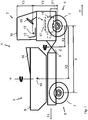
- the single figure shows a schematic, not to scale side view of a work vehicle, in particular a so-called dumper.
- the working vehicle 1 has a driving unit 2 and a trough unit 3, which are coupled to a hinge 9 in such a way that an articulated steering results by means of the vertical axis Z formed thereby.
- first axis 5 serving as a front axle first axis 5 is provided at the front ends of which wheel hubs are arranged, which carry corresponding wheels 7 in a known manner.
- second axis 6 serving as a rear axle second axis 6 is provided on the trough unit 3, at the front ends of which wheel hubs are likewise arranged, which carry corresponding wheels 7.
- the first and second axes 5, 6 are rigid, i. firmly arranged in their orientation to the respective driving unit 2 and trough unit 3.
- the first axis 5 is arranged on the driving unit 2.
- a drive motor 4 which is an internal combustion engine in the example shown, but can also be configured as an electric motor.
- a vehicle seat 12, a steering wheel 19 and a cab 16 are arranged on the driving unit 2.
- the cab 16 is optional and could also be replaced by a roll bar.
- the second axis 6 and a trough 8 are arranged.
- the trough 8 serves to receive the payload, in particular bulk material, and can be tilted with an unloading device, not shown.
- the work vehicle 1 can move in the main travel direction 11 by means of the drive motor 4.
- the driving unit 2 moves ahead and the tray unit 3 follows.
- the driver's seat 12 is aligned in the direction of the main travel direction 11 so that an operator looks in the direction of the main travel direction 11.
- the driver's seat 12 is designed to be rotatable so that it can be rotated when the working vehicle 1 is to travel in a secondary driving direction 13, ie, backwards.
- a secondary driving direction 13 ie, backwards.
- the necessary for the operation of the vehicle controls are also designed to be rotatable and / or double available.
- the tray unit 3 moves ahead and the drive unit 2 follows this. The operator can look on the rotated seat 12 in the direction of the secondary driving direction 13, which makes the drive safer.
- the work vehicle is driven by means of the drive motor 4.
- a hydraulic pump is arranged on the engine, which supplies the necessary pressure or volume flow in order to drive a hydraulic motor.
- the hydraulic motor drives the wheels.
- the other functions, such as the drive of the tilting system of the trough and also the pivoting of the trough and the articulated steering are hydrostatically driven by the hydraulic pump.
- the vehicle seat 12 is rotatable. This allows higher speeds in the reverse drive, so that the work vehicle as stable as possible, not only in forward drive but also in reverse drive, i. must be stable. However, the greatest possible safety is also necessary for machines which do not have a rotatable driver's seat, so that a rotatable driver's seat is not a feature which is necessary according to the invention.
- the wheelbase i. the distance between the first and second axis proved to be suitable.
- the horizontal distance X between the center of the axis of rotation of the first axis 5 and the center of the axis of rotation of the second axis 6 is 2700 mm in the embodiment.
- the center here is understood to be the middle between the wheel hubs respectively arranged at the ends of the axles 5, 6.
- the vertical distance Y2 to a center point or the axis of rotation of the first axis 5 and the seat index point 15 in the exemplary embodiment is 1403 mm. As a relation to the distance X, this results in 0.52.
- the vertical distance Y3 between the seat index point 15 and a roof bottom of the cab 16 is 1000mm. As a relation to the distance X, this results in 0.37.
- the diameter of an envelope in the selected embodiment is 3530mm. As a relation to the distance X, this results in 1.31.
- the relationship between the vertical distance Y2 between the axial center of the first axis 5 and the seat index point 15 and the vertical distance Y3 between the seat index point 15 and the roof bottom of the car 16 has been characteristic.
- the dimensions are in the selected embodiment for the distance from the axis 5 and the seat index point 1403 mm and for the distance from the seat index point 15 and the roof bottom of the cabin 1000mm.
Landscapes
- Engineering & Computer Science (AREA)
- Mechanical Engineering (AREA)
- Mining & Mineral Resources (AREA)
- Civil Engineering (AREA)
- General Engineering & Computer Science (AREA)
- Structural Engineering (AREA)
- Transportation (AREA)
- Aviation & Aerospace Engineering (AREA)
- Chemical & Material Sciences (AREA)
- Combustion & Propulsion (AREA)
- Body Structure For Vehicles (AREA)
- Jigging Conveyors (AREA)
Priority Applications (3)
| Application Number | Priority Date | Filing Date | Title |
|---|---|---|---|
| ES18168580T ES2961873T3 (es) | 2018-04-20 | 2018-04-20 | Vehículo de trabajo con estabilidad mejorada |
| DK18168580.1T DK3556946T3 (da) | 2018-04-20 | 2018-04-20 | Arbejdskøretøj med forbedret stabilitet |
| EP18168580.1A EP3556946B1 (fr) | 2018-04-20 | 2018-04-20 | Engin de travail à stabilité améliorée |
Applications Claiming Priority (1)
| Application Number | Priority Date | Filing Date | Title |
|---|---|---|---|
| EP18168580.1A EP3556946B1 (fr) | 2018-04-20 | 2018-04-20 | Engin de travail à stabilité améliorée |
Publications (2)
| Publication Number | Publication Date |
|---|---|
| EP3556946A1 true EP3556946A1 (fr) | 2019-10-23 |
| EP3556946B1 EP3556946B1 (fr) | 2023-08-30 |
Family
ID=62044603
Family Applications (1)
| Application Number | Title | Priority Date | Filing Date |
|---|---|---|---|
| EP18168580.1A Active EP3556946B1 (fr) | 2018-04-20 | 2018-04-20 | Engin de travail à stabilité améliorée |
Country Status (3)
| Country | Link |
|---|---|
| EP (1) | EP3556946B1 (fr) |
| DK (1) | DK3556946T3 (fr) |
| ES (1) | ES2961873T3 (fr) |
Citations (6)
| Publication number | Priority date | Publication date | Assignee | Title |
|---|---|---|---|---|
| FR2846930A1 (fr) * | 2002-11-07 | 2004-05-14 | Bernard Coeuret | Vehicule leger de chantier, notamment vehicule a benne |
| EP2058439A2 (fr) * | 2007-11-12 | 2009-05-13 | NC Engineering (Hamiltonsbawn) Limited | Véhicule articulé |
| US20110005848A1 (en) * | 2008-02-29 | 2011-01-13 | Volvo Construction Equipment Ab | Work machine |
| US20140145415A1 (en) * | 2011-05-06 | 2014-05-29 | Volvo Construction Equipment Ab | Method for controlling a working machine, and a working machine |
| DE102015001905A1 (de) | 2015-02-18 | 2016-08-18 | Wacker Neuson Linz Gmbh | Überwachungseinrichtung für den Beladungszustand eines Schüttgutfahrzeugs |
| DE202016100964U1 (de) * | 2016-02-24 | 2017-05-26 | Wacker Neuson Linz Gmbh | Arbeitsfahrzeug mit drehbarem Fahrersitz |
-
2018
- 2018-04-20 DK DK18168580.1T patent/DK3556946T3/da active
- 2018-04-20 EP EP18168580.1A patent/EP3556946B1/fr active Active
- 2018-04-20 ES ES18168580T patent/ES2961873T3/es active Active
Patent Citations (6)
| Publication number | Priority date | Publication date | Assignee | Title |
|---|---|---|---|---|
| FR2846930A1 (fr) * | 2002-11-07 | 2004-05-14 | Bernard Coeuret | Vehicule leger de chantier, notamment vehicule a benne |
| EP2058439A2 (fr) * | 2007-11-12 | 2009-05-13 | NC Engineering (Hamiltonsbawn) Limited | Véhicule articulé |
| US20110005848A1 (en) * | 2008-02-29 | 2011-01-13 | Volvo Construction Equipment Ab | Work machine |
| US20140145415A1 (en) * | 2011-05-06 | 2014-05-29 | Volvo Construction Equipment Ab | Method for controlling a working machine, and a working machine |
| DE102015001905A1 (de) | 2015-02-18 | 2016-08-18 | Wacker Neuson Linz Gmbh | Überwachungseinrichtung für den Beladungszustand eines Schüttgutfahrzeugs |
| DE202016100964U1 (de) * | 2016-02-24 | 2017-05-26 | Wacker Neuson Linz Gmbh | Arbeitsfahrzeug mit drehbarem Fahrersitz |
Also Published As
| Publication number | Publication date |
|---|---|
| EP3556946B1 (fr) | 2023-08-30 |
| DK3556946T3 (da) | 2023-10-16 |
| ES2961873T3 (es) | 2024-03-14 |
Similar Documents
| Publication | Publication Date | Title |
|---|---|---|
| DE69515809T2 (de) | Fahrgestell mit verstellbarer Spurbreite | |
| DE102013208484B4 (de) | Vorrichtung zum Bearbeiten von Straßen- oder Bodenoberflächen, sowie Verfahren zum Lenken einer Straßenfräsmaschine | |
| DE19612559A1 (de) | Mehrzwecke-Baufahrzeug | |
| EP2953844A1 (fr) | Véhicule | |
| DE102018209593A1 (de) | Fahrzeuglenksystem, Fahrwerk und Fahrzeug | |
| WO1984002316A1 (fr) | Vehicule pour petits travaux | |
| EP2801664B1 (fr) | Fraiseuse routière destinée à traiter les surfaces routières et de sol | |
| DE4219876C2 (de) | Radfahrzeug, insbesondere Forstmaschine | |
| DE102017212127A1 (de) | Achsbaugruppe für ein Schwerlastfahrzeug und Schwerlastfahrzeug mit wenigstens einer derartigen Achsbaugruppe | |
| WO2020025201A1 (fr) | Attelage comprenant un véhicule tracteur et une remorque, véhicule tracteur, remorque et procédé pour la distribution de charge par essieu dans un attelage | |
| DE102019216132B4 (de) | Raupenkettenführungssystem zur verwendung mit einer arbeitsmaschine und einem raupenkettenfahrwerk | |
| DE2156282C3 (de) | Maschine zum schichtweisen Abtragen von verschlissenen Straßendecken | |
| DE102019105566B4 (de) | Fahrwerksanordnung für ein Kraftfahrzeug sowie Verfahren zum Betreiben eines Kraftfahrzeuges | |
| DE102015212580A1 (de) | Radaufhängungsanordnung | |
| DE602005002020T2 (de) | Lenkachse für fahrzeuge, insbesondere für arbeitsmaschinen oder ackerschlepper | |
| DE102015220497A1 (de) | Raupenfahrzeug, Verfahren zum Betreiben eines Raupenfahrzeugs | |
| EP3556946B1 (fr) | Engin de travail à stabilité améliorée | |
| DE2905528A1 (de) | Achsschenkelgelenktes kraftfahrzeug | |
| DE2243290A1 (de) | Transportvorrichtung | |
| DE102005037389B4 (de) | Vielzweckarbeitsgerät | |
| DE102017116637A1 (de) | Gezogenes landwirtschaftliches Arbeitsgerät | |
| DE2453017B2 (de) | Fahrzeug für Arbeits- und Transportzwecke | |
| DE102017203666A1 (de) | Lenkvorrichtung für ein Fahrzeug und Verfahren zum Lenken eines Fahrzeugs | |
| DE10064430B4 (de) | Selbstfahrendes Gerät | |
| DE102012019491B4 (de) | Vorrichtung zur Verlagerung des Schwerpunkts einer Baumaschine |
Legal Events
| Date | Code | Title | Description |
|---|---|---|---|
| PUAI | Public reference made under article 153(3) epc to a published international application that has entered the european phase |
Free format text: ORIGINAL CODE: 0009012 |
|
| STAA | Information on the status of an ep patent application or granted ep patent |
Free format text: STATUS: THE APPLICATION HAS BEEN PUBLISHED |
|
| AK | Designated contracting states |
Kind code of ref document: A1 Designated state(s): AL AT BE BG CH CY CZ DE DK EE ES FI FR GB GR HR HU IE IS IT LI LT LU LV MC MK MT NL NO PL PT RO RS SE SI SK SM TR |
|
| AX | Request for extension of the european patent |
Extension state: BA ME |
|
| RIN1 | Information on inventor provided before grant (corrected) |
Inventor name: ERLINGER, JOSEF |
|
| STAA | Information on the status of an ep patent application or granted ep patent |
Free format text: STATUS: REQUEST FOR EXAMINATION WAS MADE |
|
| 17P | Request for examination filed |
Effective date: 20200416 |
|
| RBV | Designated contracting states (corrected) |
Designated state(s): AL AT BE BG CH CY CZ DE DK EE ES FI FR GB GR HR HU IE IS IT LI LT LU LV MC MK MT NL NO PL PT RO RS SE SI SK SM TR |
|
| GRAP | Despatch of communication of intention to grant a patent |
Free format text: ORIGINAL CODE: EPIDOSNIGR1 |
|
| STAA | Information on the status of an ep patent application or granted ep patent |
Free format text: STATUS: GRANT OF PATENT IS INTENDED |
|
| RIC1 | Information provided on ipc code assigned before grant |
Ipc: B62D 21/18 20060101ALI20230302BHEP Ipc: B60N 2/24 20060101ALI20230302BHEP Ipc: B62D 53/02 20060101ALI20230302BHEP Ipc: B60N 2/14 20060101ALI20230302BHEP Ipc: E02F 3/34 20060101ALI20230302BHEP Ipc: E02F 9/08 20060101ALI20230302BHEP Ipc: E02F 9/16 20060101AFI20230302BHEP |
|
| INTG | Intention to grant announced |
Effective date: 20230322 |
|
| GRAS | Grant fee paid |
Free format text: ORIGINAL CODE: EPIDOSNIGR3 |
|
| GRAA | (expected) grant |
Free format text: ORIGINAL CODE: 0009210 |
|
| STAA | Information on the status of an ep patent application or granted ep patent |
Free format text: STATUS: THE PATENT HAS BEEN GRANTED |
|
| AK | Designated contracting states |
Kind code of ref document: B1 Designated state(s): AL AT BE BG CH CY CZ DE DK EE ES FI FR GB GR HR HU IE IS IT LI LT LU LV MC MK MT NL NO PL PT RO RS SE SI SK SM TR |
|
| REG | Reference to a national code |
Ref country code: GB Ref legal event code: FG4D Free format text: NOT ENGLISH |
|
| REG | Reference to a national code |
Ref country code: CH Ref legal event code: EP |
|
| REG | Reference to a national code |
Ref country code: DE Ref legal event code: R096 Ref document number: 502018013103 Country of ref document: DE |
|
| REG | Reference to a national code |
Ref country code: IE Ref legal event code: FG4D Free format text: LANGUAGE OF EP DOCUMENT: GERMAN |
|
| REG | Reference to a national code |
Ref country code: DK Ref legal event code: T3 Effective date: 20231013 |
|
| REG | Reference to a national code |
Ref country code: LT Ref legal event code: MG9D |
|
| REG | Reference to a national code |
Ref country code: NL Ref legal event code: MP Effective date: 20230830 |
|
| PG25 | Lapsed in a contracting state [announced via postgrant information from national office to epo] |
Ref country code: GR Free format text: LAPSE BECAUSE OF FAILURE TO SUBMIT A TRANSLATION OF THE DESCRIPTION OR TO PAY THE FEE WITHIN THE PRESCRIBED TIME-LIMIT Effective date: 20231201 |
|
| PG25 | Lapsed in a contracting state [announced via postgrant information from national office to epo] |
Ref country code: IS Free format text: LAPSE BECAUSE OF FAILURE TO SUBMIT A TRANSLATION OF THE DESCRIPTION OR TO PAY THE FEE WITHIN THE PRESCRIBED TIME-LIMIT Effective date: 20231230 |
|
| PG25 | Lapsed in a contracting state [announced via postgrant information from national office to epo] |
Ref country code: SE Free format text: LAPSE BECAUSE OF FAILURE TO SUBMIT A TRANSLATION OF THE DESCRIPTION OR TO PAY THE FEE WITHIN THE PRESCRIBED TIME-LIMIT Effective date: 20230830 Ref country code: RS Free format text: LAPSE BECAUSE OF FAILURE TO SUBMIT A TRANSLATION OF THE DESCRIPTION OR TO PAY THE FEE WITHIN THE PRESCRIBED TIME-LIMIT Effective date: 20230830 Ref country code: NO Free format text: LAPSE BECAUSE OF FAILURE TO SUBMIT A TRANSLATION OF THE DESCRIPTION OR TO PAY THE FEE WITHIN THE PRESCRIBED TIME-LIMIT Effective date: 20231130 Ref country code: LV Free format text: LAPSE BECAUSE OF FAILURE TO SUBMIT A TRANSLATION OF THE DESCRIPTION OR TO PAY THE FEE WITHIN THE PRESCRIBED TIME-LIMIT Effective date: 20230830 Ref country code: LT Free format text: LAPSE BECAUSE OF FAILURE TO SUBMIT A TRANSLATION OF THE DESCRIPTION OR TO PAY THE FEE WITHIN THE PRESCRIBED TIME-LIMIT Effective date: 20230830 Ref country code: IS Free format text: LAPSE BECAUSE OF FAILURE TO SUBMIT A TRANSLATION OF THE DESCRIPTION OR TO PAY THE FEE WITHIN THE PRESCRIBED TIME-LIMIT Effective date: 20231230 Ref country code: HR Free format text: LAPSE BECAUSE OF FAILURE TO SUBMIT A TRANSLATION OF THE DESCRIPTION OR TO PAY THE FEE WITHIN THE PRESCRIBED TIME-LIMIT Effective date: 20230830 Ref country code: GR Free format text: LAPSE BECAUSE OF FAILURE TO SUBMIT A TRANSLATION OF THE DESCRIPTION OR TO PAY THE FEE WITHIN THE PRESCRIBED TIME-LIMIT Effective date: 20231201 Ref country code: FI Free format text: LAPSE BECAUSE OF FAILURE TO SUBMIT A TRANSLATION OF THE DESCRIPTION OR TO PAY THE FEE WITHIN THE PRESCRIBED TIME-LIMIT Effective date: 20230830 |
|
| PG25 | Lapsed in a contracting state [announced via postgrant information from national office to epo] |
Ref country code: PL Free format text: LAPSE BECAUSE OF FAILURE TO SUBMIT A TRANSLATION OF THE DESCRIPTION OR TO PAY THE FEE WITHIN THE PRESCRIBED TIME-LIMIT Effective date: 20230830 Ref country code: NL Free format text: LAPSE BECAUSE OF FAILURE TO SUBMIT A TRANSLATION OF THE DESCRIPTION OR TO PAY THE FEE WITHIN THE PRESCRIBED TIME-LIMIT Effective date: 20230830 |
|
| REG | Reference to a national code |
Ref country code: ES Ref legal event code: FG2A Ref document number: 2961873 Country of ref document: ES Kind code of ref document: T3 Effective date: 20240314 |
|
| PG25 | Lapsed in a contracting state [announced via postgrant information from national office to epo] |
Ref country code: SM Free format text: LAPSE BECAUSE OF FAILURE TO SUBMIT A TRANSLATION OF THE DESCRIPTION OR TO PAY THE FEE WITHIN THE PRESCRIBED TIME-LIMIT Effective date: 20230830 Ref country code: RO Free format text: LAPSE BECAUSE OF FAILURE TO SUBMIT A TRANSLATION OF THE DESCRIPTION OR TO PAY THE FEE WITHIN THE PRESCRIBED TIME-LIMIT Effective date: 20230830 Ref country code: EE Free format text: LAPSE BECAUSE OF FAILURE TO SUBMIT A TRANSLATION OF THE DESCRIPTION OR TO PAY THE FEE WITHIN THE PRESCRIBED TIME-LIMIT Effective date: 20230830 Ref country code: PT Free format text: LAPSE BECAUSE OF FAILURE TO SUBMIT A TRANSLATION OF THE DESCRIPTION OR TO PAY THE FEE WITHIN THE PRESCRIBED TIME-LIMIT Effective date: 20240102 Ref country code: SK Free format text: LAPSE BECAUSE OF FAILURE TO SUBMIT A TRANSLATION OF THE DESCRIPTION OR TO PAY THE FEE WITHIN THE PRESCRIBED TIME-LIMIT Effective date: 20230830 |
|
| REG | Reference to a national code |
Ref country code: DE Ref legal event code: R097 Ref document number: 502018013103 Country of ref document: DE |
|
| PLBE | No opposition filed within time limit |
Free format text: ORIGINAL CODE: 0009261 |
|
| STAA | Information on the status of an ep patent application or granted ep patent |
Free format text: STATUS: NO OPPOSITION FILED WITHIN TIME LIMIT |
|
| PG25 | Lapsed in a contracting state [announced via postgrant information from national office to epo] |
Ref country code: SI Free format text: LAPSE BECAUSE OF FAILURE TO SUBMIT A TRANSLATION OF THE DESCRIPTION OR TO PAY THE FEE WITHIN THE PRESCRIBED TIME-LIMIT Effective date: 20230830 |
|
| 26N | No opposition filed |
Effective date: 20240603 |
|
| PG25 | Lapsed in a contracting state [announced via postgrant information from national office to epo] |
Ref country code: BG Free format text: LAPSE BECAUSE OF FAILURE TO SUBMIT A TRANSLATION OF THE DESCRIPTION OR TO PAY THE FEE WITHIN THE PRESCRIBED TIME-LIMIT Effective date: 20230830 |
|
| PG25 | Lapsed in a contracting state [announced via postgrant information from national office to epo] |
Ref country code: MC Free format text: LAPSE BECAUSE OF FAILURE TO SUBMIT A TRANSLATION OF THE DESCRIPTION OR TO PAY THE FEE WITHIN THE PRESCRIBED TIME-LIMIT Effective date: 20230830 |
|
| PG25 | Lapsed in a contracting state [announced via postgrant information from national office to epo] |
Ref country code: MC Free format text: LAPSE BECAUSE OF FAILURE TO SUBMIT A TRANSLATION OF THE DESCRIPTION OR TO PAY THE FEE WITHIN THE PRESCRIBED TIME-LIMIT Effective date: 20230830 Ref country code: BG Free format text: LAPSE BECAUSE OF FAILURE TO SUBMIT A TRANSLATION OF THE DESCRIPTION OR TO PAY THE FEE WITHIN THE PRESCRIBED TIME-LIMIT Effective date: 20230830 |
|
| PG25 | Lapsed in a contracting state [announced via postgrant information from national office to epo] |
Ref country code: LU Free format text: LAPSE BECAUSE OF NON-PAYMENT OF DUE FEES Effective date: 20240420 |
|
| REG | Reference to a national code |
Ref country code: BE Ref legal event code: MM Effective date: 20240430 |
|
| PG25 | Lapsed in a contracting state [announced via postgrant information from national office to epo] |
Ref country code: LU Free format text: LAPSE BECAUSE OF NON-PAYMENT OF DUE FEES Effective date: 20240420 |
|
| P01 | Opt-out of the competence of the unified patent court (upc) registered |
Free format text: CASE NUMBER: APP_65034/2024 Effective date: 20241209 |
|
| PG25 | Lapsed in a contracting state [announced via postgrant information from national office to epo] |
Ref country code: BE Free format text: LAPSE BECAUSE OF NON-PAYMENT OF DUE FEES Effective date: 20240430 |
|
| PG25 | Lapsed in a contracting state [announced via postgrant information from national office to epo] |
Ref country code: BE Free format text: LAPSE BECAUSE OF NON-PAYMENT OF DUE FEES Effective date: 20240430 |
|
| PG25 | Lapsed in a contracting state [announced via postgrant information from national office to epo] |
Ref country code: IE Free format text: LAPSE BECAUSE OF NON-PAYMENT OF DUE FEES Effective date: 20240420 |
|
| PGFP | Annual fee paid to national office [announced via postgrant information from national office to epo] |
Ref country code: DE Payment date: 20250417 Year of fee payment: 8 |
|
| PGFP | Annual fee paid to national office [announced via postgrant information from national office to epo] |
Ref country code: ES Payment date: 20250519 Year of fee payment: 8 Ref country code: DK Payment date: 20250423 Year of fee payment: 8 |
|
| PGFP | Annual fee paid to national office [announced via postgrant information from national office to epo] |
Ref country code: IT Payment date: 20250430 Year of fee payment: 8 |
|
| PGFP | Annual fee paid to national office [announced via postgrant information from national office to epo] |
Ref country code: FR Payment date: 20250422 Year of fee payment: 8 |
|
| PGFP | Annual fee paid to national office [announced via postgrant information from national office to epo] |
Ref country code: CH Payment date: 20250501 Year of fee payment: 8 |
|
| PGFP | Annual fee paid to national office [announced via postgrant information from national office to epo] |
Ref country code: AT Payment date: 20250416 Year of fee payment: 8 |
|
| PGFP | Annual fee paid to national office [announced via postgrant information from national office to epo] |
Ref country code: CZ Payment date: 20250404 Year of fee payment: 8 |
|
| PG25 | Lapsed in a contracting state [announced via postgrant information from national office to epo] |
Ref country code: CY Free format text: LAPSE BECAUSE OF FAILURE TO SUBMIT A TRANSLATION OF THE DESCRIPTION OR TO PAY THE FEE WITHIN THE PRESCRIBED TIME-LIMIT; INVALID AB INITIO Effective date: 20180420 |
|
| PG25 | Lapsed in a contracting state [announced via postgrant information from national office to epo] |
Ref country code: HU Free format text: LAPSE BECAUSE OF FAILURE TO SUBMIT A TRANSLATION OF THE DESCRIPTION OR TO PAY THE FEE WITHIN THE PRESCRIBED TIME-LIMIT; INVALID AB INITIO Effective date: 20180420 |
|
| PGFP | Annual fee paid to national office [announced via postgrant information from national office to epo] |
Ref country code: GB Payment date: 20260324 Year of fee payment: 9 |