EP3556963A1 - Verbindungsvorrichtung der extremitäten von verkleidungslamellen - Google Patents
Verbindungsvorrichtung der extremitäten von verkleidungslamellen Download PDFInfo
- Publication number
- EP3556963A1 EP3556963A1 EP18167781.6A EP18167781A EP3556963A1 EP 3556963 A1 EP3556963 A1 EP 3556963A1 EP 18167781 A EP18167781 A EP 18167781A EP 3556963 A1 EP3556963 A1 EP 3556963A1
- Authority
- EP
- European Patent Office
- Prior art keywords
- blades
- fact
- blade
- tips
- preformed
- Prior art date
- Legal status (The legal status is an assumption and is not a legal conclusion. Google has not performed a legal analysis and makes no representation as to the accuracy of the status listed.)
- Granted
Links
Images








Classifications
-
- E—FIXED CONSTRUCTIONS
- E04—BUILDING
- E04F—FINISHING WORK ON BUILDINGS, e.g. STAIRS, FLOORS
- E04F13/00—Coverings or linings, e.g. for walls or ceilings
- E04F13/07—Coverings or linings, e.g. for walls or ceilings composed of covering or lining elements; Sub-structures therefor; Fastening means therefor
- E04F13/08—Coverings or linings, e.g. for walls or ceilings composed of covering or lining elements; Sub-structures therefor; Fastening means therefor composed of a plurality of similar covering or lining elements
- E04F13/0801—Separate fastening elements
- E04F13/0803—Separate fastening elements with load-supporting elongated furring elements between wall and covering elements
- E04F13/081—Separate fastening elements with load-supporting elongated furring elements between wall and covering elements with additional fastening elements between furring elements and covering elements
- E04F13/0814—Separate fastening elements with load-supporting elongated furring elements between wall and covering elements with additional fastening elements between furring elements and covering elements fixed by means of clamping action
-
- E—FIXED CONSTRUCTIONS
- E04—BUILDING
- E04F—FINISHING WORK ON BUILDINGS, e.g. STAIRS, FLOORS
- E04F13/00—Coverings or linings, e.g. for walls or ceilings
- E04F13/07—Coverings or linings, e.g. for walls or ceilings composed of covering or lining elements; Sub-structures therefor; Fastening means therefor
- E04F13/08—Coverings or linings, e.g. for walls or ceilings composed of covering or lining elements; Sub-structures therefor; Fastening means therefor composed of a plurality of similar covering or lining elements
- E04F13/0801—Separate fastening elements
- E04F13/0803—Separate fastening elements with load-supporting elongated furring elements between wall and covering elements
- E04F13/081—Separate fastening elements with load-supporting elongated furring elements between wall and covering elements with additional fastening elements between furring elements and covering elements
- E04F13/0816—Separate fastening elements with load-supporting elongated furring elements between wall and covering elements with additional fastening elements between furring elements and covering elements the additional fastening elements extending into the back side of the covering elements
- E04F13/0817—Separate fastening elements with load-supporting elongated furring elements between wall and covering elements with additional fastening elements between furring elements and covering elements the additional fastening elements extending into the back side of the covering elements extending completely through the covering elements
-
- E—FIXED CONSTRUCTIONS
- E04—BUILDING
- E04F—FINISHING WORK ON BUILDINGS, e.g. STAIRS, FLOORS
- E04F13/00—Coverings or linings, e.g. for walls or ceilings
- E04F13/07—Coverings or linings, e.g. for walls or ceilings composed of covering or lining elements; Sub-structures therefor; Fastening means therefor
- E04F13/08—Coverings or linings, e.g. for walls or ceilings composed of covering or lining elements; Sub-structures therefor; Fastening means therefor composed of a plurality of similar covering or lining elements
- E04F13/0801—Separate fastening elements
- E04F13/0803—Separate fastening elements with load-supporting elongated furring elements between wall and covering elements
- E04F13/081—Separate fastening elements with load-supporting elongated furring elements between wall and covering elements with additional fastening elements between furring elements and covering elements
- E04F13/0821—Separate fastening elements with load-supporting elongated furring elements between wall and covering elements with additional fastening elements between furring elements and covering elements the additional fastening elements located in-between two adjacent covering elements
-
- E—FIXED CONSTRUCTIONS
- E04—BUILDING
- E04F—FINISHING WORK ON BUILDINGS, e.g. STAIRS, FLOORS
- E04F13/00—Coverings or linings, e.g. for walls or ceilings
- E04F13/07—Coverings or linings, e.g. for walls or ceilings composed of covering or lining elements; Sub-structures therefor; Fastening means therefor
- E04F13/08—Coverings or linings, e.g. for walls or ceilings composed of covering or lining elements; Sub-structures therefor; Fastening means therefor composed of a plurality of similar covering or lining elements
- E04F13/0889—Coverings or linings, e.g. for walls or ceilings composed of covering or lining elements; Sub-structures therefor; Fastening means therefor composed of a plurality of similar covering or lining elements characterised by the joints between neighbouring elements, e.g. with joint fillings or with tongue and groove connections
- E04F13/0894—Coverings or linings, e.g. for walls or ceilings composed of covering or lining elements; Sub-structures therefor; Fastening means therefor composed of a plurality of similar covering or lining elements characterised by the joints between neighbouring elements, e.g. with joint fillings or with tongue and groove connections with tongue and groove connections
-
- E—FIXED CONSTRUCTIONS
- E04—BUILDING
- E04F—FINISHING WORK ON BUILDINGS, e.g. STAIRS, FLOORS
- E04F13/00—Coverings or linings, e.g. for walls or ceilings
- E04F13/07—Coverings or linings, e.g. for walls or ceilings composed of covering or lining elements; Sub-structures therefor; Fastening means therefor
- E04F13/08—Coverings or linings, e.g. for walls or ceilings composed of covering or lining elements; Sub-structures therefor; Fastening means therefor composed of a plurality of similar covering or lining elements
- E04F13/18—Coverings or linings, e.g. for walls or ceilings composed of covering or lining elements; Sub-structures therefor; Fastening means therefor composed of a plurality of similar covering or lining elements of organic plastics with or without reinforcements or filling materials or with an outer layer of organic plastics with or without reinforcements or filling materials; plastic tiles
-
- E—FIXED CONSTRUCTIONS
- E04—BUILDING
- E04F—FINISHING WORK ON BUILDINGS, e.g. STAIRS, FLOORS
- E04F2201/00—Joining sheets or plates or panels
- E04F2201/05—Separate connectors or inserts, e.g. pegs, pins, keys or strips
- E04F2201/0511—Strips or bars, e.g. nailing strips
-
- E—FIXED CONSTRUCTIONS
- E04—BUILDING
- E04F—FINISHING WORK ON BUILDINGS, e.g. STAIRS, FLOORS
- E04F2201/00—Joining sheets or plates or panels
- E04F2201/05—Separate connectors or inserts, e.g. pegs, pins, keys or strips
- E04F2201/0517—U- or C-shaped brackets and clamps
Definitions
- the present invention relates to the field of exterior cladding type facades and including adaptations to ensure, under the best conditions, the connection between the ends of the blades component cladding.
- Cladding can be defined in a general manner by a facade cladding attached to a frame itself attached to the wall.
- This coating is composed of manufactured parts and more particularly by blades, that is to say substantially flat and elongated parts. These blades are not only fixed on the frame but also cooperate with each other to avoid any inter-blade space. To do this, these blades are conventionally preformed on their longitudinal edges to allow interpenetration of the longitudinal edges of adjacent juxtaposed blades.
- the document DE 4215273 describes a means for optimizing the fixing of these longitudinal edges.
- This device comprises at least one connection assembly and pre-formed end-to-end blades for accommodating it, said connecting assembly being formed of a lamella on the same side of which two points are projecting, each point cooperating with a hole made in the end of a different blade.
- connection assemblies optimizes the fixation.
- This feature is particularly advantageous in that it does not require the creation of a complex profile at the ends of the blades for butting purposes. Indeed, according to the invention, drilling holes in each end is sufficient which makes easier the operations to be performed on the blades. These operations can be performed on the installation site.
- the invention avoids embrittlement of the ends to be abutted and avoids the rupture of the latter in case of expansion.
- the invention thus provides a simple and practical solution to achieve by means of an additional connecting device, an abutment of the blades of a cladding type external cladding without the disadvantages of the solutions of the prior art.
- the device is remarkable in that the preforming of the longitudinal edges of the blades consists of the realization of a U-profile groove whose central bar is pierced, parallel to the surface to which the blades are fixed, at the end of the blade of one of said holes for passing said points of the connection assembly.
- the device is remarkable in that the preformation longitudinal edges of the blades consists of producing a tongue cooperating with said U-shaped groove, said tongue being pierced, perpendicular to the facade to which the blades are fixed, at the end of the blade of a said through holes of said tips of the link assembly.
- connection sets are positioned in the rabbet or in the tongue covered by the rabbet, they remain invisible from the outside.
- the tips of the ends projecting lamellae open on the rear face of the blades and cooperate with a skirt that marries the rear face of the two abutting ends of the blades, said skirt being preformed with orifices allowing it to be positioned on said points.
- This skirt provides the creation of an obstacle behind each inter-blade end space ensuring the protection of the facade.
- the ends of said tips are preformed flats parallel to the facade when the connecting assemblies are engaged in the holes drilled in the blades parallel to the surface to which the blades are fixed. These flats will facilitate the positioning of the skirts.
- the body of said tips comprises a cylindrical portion preformed on their face coming opposite radial splines. The presence of these grooves and their orientation will tend to bring the ends of the blades to at least reduce or eliminate the inter-blade space.
- said skirt comprises on the rear face positioning fins coming into contact with the ends of said points to finalize the fastenings of both the skirts and connecting assemblies tending to bring the points between them. This approximation tends to maintain the binding assembly in position and prevent yawning in the butting.
- connection sub-assembly with symmetrical complementary shapes so that the points of a first connection sub-assembly can cooperate with the peaks of a second return link sub-assembly, said tips being preformed with complementary shapes allowing their fitting and / or clipping once arranged in facing relation.
- said tips are formed of a cylindrical body whose distal end is preformed with an external collar forming a stop, said distal end being split to allow its elastic deformation.
- the slat cooperates with a riser to create a spacer interposed between the tongues and the bottom of the grooves of the blades by positioning in the U-groove to provide a different spacing between the longitudinal edges of the blades.
- the strip is preformed to have a thickness corresponding to the desired enhancement.
- the blades, the connecting assemblies and the skirts are made of the same synthetic material. According to another particularly advantageous feature of the invention, the blades, the connecting assemblies and the skirts are made of polyamide PA6.
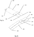
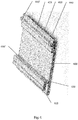
- the linking device As illustrated on the drawing of the figure 1 , the linking device, referenced D as a whole, comprises a plurality connecting assemblies 100 formed by a slat 110 on one side of which are projected two points 120 and 130. These binding assemblies will serve as staples to the blades placed end-to-end with an outer covering such as those illustrated by the drawing of the figure 5 staples that will cooperate with holes drilled in the end of each blade coming vis-à-vis.
- the link assembly 100 may be associated with a riser 200 whose utility will be described below.
- Said riser is formed by a parallelepipedal wedge having, on one of its faces, a groove 210 for retaining the lamella 110 of the connection assembly 100.
- the device further comprises a skirt 300 interposed between the rear face of the blades 400 and the front (not shown) by marrying said rear face and cooperating with the connecting assemblies 100.
- This skirt 300 through which holes 310 and 320, has on the rear face of the positioning fins 330 and 340 and, on its upper edge, needles 350 and 360 whose utility will be described below.
- the spacing between the holes from one blade end to the other corresponds to the spacing of the tips 120 and 130 of the connecting assembly 100.
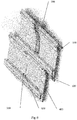
- an additional spacing is sought in the longitudinal connection between the blades 400, which is why an extension 200 is associated with certain connection assemblies 100 (see also figure 2 ) positioned in the U-groove to provide a different spacing between the longitudinal edges of the blades.
- the link assemblies 100 are positioned in the sheet or on the tongue itself covered with the rabbet so that the connection assemblies are invisible from the outside of the facade.
- the ends of the tips 120 and 130 projecting lamellae 110 of each connecting assembly 100 open on the rear face of the blades 400 and cooperate with a skirt 300 coming to match the rear face of the two abutting ends of the blades 400, said skirt being preformed openings 310 and 320 which allow it to come to position on said points.
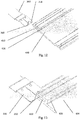
- the ends of said tips 120 and 130 are preformed with flats 121 and 131 parallel to the front or the rear face of the blades 400 (when the link assembly is positioned in the holes 430, 430 'of axis parallel to the facade or the back side of the blade 400).
- These flats 121 and 131 find their utility in the sliding of the skirt 300 between said flats 121 and 131 and the rear face of the flanges. blades.
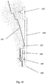
- the flattened surface as illustrated in the drawings of figures 9 , 10 and 11 , facilitates positioning and holding in position.
- the fins 330 and 340 of the rear faces of the skirts 300 (cf. figure 3 ) contact the ends of said tips to finalize the fastenings of both the skirts 300 and linkage assemblies 100 tending to bring the tips 120 and 130 together.
- the bodies of said tips 120 and 130 comprise on their base a preformed cylindrical portion on their face coming opposite radial grooves 122 and 132. It is understood that these grooves 122 and 132 will create an additional constraint tending to bring the ends linked by the link sets 100.
- the pins 350 and 360 preformed on the upper edge of the skirts form a template at least marking in the groove of the edge 410 of the blade 400 for drilling on site holes 430 and 430 '.
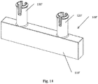
- FIG. 14 , 15 and 16 illustrate another embodiment for the link assembly.
- This link assembly referenced 100 'as a whole is formed of a lamella 110' (also forming a riser) on the same side of which project two points 120 'and 130', each point 120 'and 130' cooperating with a hole made in the end of a different blade to ensure the connection.
- said tips 120 'and 130' are formed of a cylindrical body whose distal end is preformed with an outer collar 121 'and 131' forming a stop, said distal end being slotted to allow its elastic deformation.
- this link assembly clips directly into the blades to be abutted. This clipping ensures the joining of the blades 600 and 600 'and the holding in position of the link assembly 100'.
Landscapes
- Engineering & Computer Science (AREA)
- Architecture (AREA)
- Civil Engineering (AREA)
- Structural Engineering (AREA)
- Finishing Walls (AREA)
- Joining Of Building Structures In Genera (AREA)
Priority Applications (4)
| Application Number | Priority Date | Filing Date | Title |
|---|---|---|---|
| EP18167781.6A EP3556963B1 (de) | 2018-04-17 | 2018-04-17 | Verbindungsvorrichtung der extremitäten von verkleidungslamellen |
| PL18167781T PL3556963T3 (pl) | 2018-04-17 | 2018-04-17 | Urządzenie do łączenia końców liniowych elementów okładzinowych |
| ES18167781T ES2843740T3 (es) | 2018-04-17 | 2018-04-17 | Dispositivo para conectar extremos de elementos de revestimiento lineales |
| PT181677816T PT3556963T (pt) | 2018-04-17 | 2018-04-17 | Dispositivo para ligar as extremidades dos elementos de revestimento linear |
Applications Claiming Priority (1)
| Application Number | Priority Date | Filing Date | Title |
|---|---|---|---|
| EP18167781.6A EP3556963B1 (de) | 2018-04-17 | 2018-04-17 | Verbindungsvorrichtung der extremitäten von verkleidungslamellen |
Publications (2)
| Publication Number | Publication Date |
|---|---|
| EP3556963A1 true EP3556963A1 (de) | 2019-10-23 |
| EP3556963B1 EP3556963B1 (de) | 2020-10-21 |
Family
ID=62017248
Family Applications (1)
| Application Number | Title | Priority Date | Filing Date |
|---|---|---|---|
| EP18167781.6A Active EP3556963B1 (de) | 2018-04-17 | 2018-04-17 | Verbindungsvorrichtung der extremitäten von verkleidungslamellen |
Country Status (4)
| Country | Link |
|---|---|
| EP (1) | EP3556963B1 (de) |
| ES (1) | ES2843740T3 (de) |
| PL (1) | PL3556963T3 (de) |
| PT (1) | PT3556963T (de) |
Citations (4)
| Publication number | Priority date | Publication date | Assignee | Title |
|---|---|---|---|---|
| US4312165A (en) * | 1978-10-03 | 1982-01-26 | Nifco, Inc. | Bracket for head of panel fastener |
| DE4215273A1 (de) | 1992-05-09 | 1993-11-18 | Dietmar Groeger | Belag zur Verkleidung von Boden-, Wand- und/oder Deckenflächen, insbesondere in der Art eines Riemenfußbodens |
| WO2010075104A2 (en) * | 2008-12-15 | 2010-07-01 | Mohawk Carpet Corporation | Tile systems and methods of making and using same |
| FR3057593A1 (fr) * | 2016-10-17 | 2018-04-20 | S2Ir | Dispositif de liaison des extremites de lames de bardage |
-
2018
- 2018-04-17 PL PL18167781T patent/PL3556963T3/pl unknown
- 2018-04-17 ES ES18167781T patent/ES2843740T3/es active Active
- 2018-04-17 PT PT181677816T patent/PT3556963T/pt unknown
- 2018-04-17 EP EP18167781.6A patent/EP3556963B1/de active Active
Patent Citations (4)
| Publication number | Priority date | Publication date | Assignee | Title |
|---|---|---|---|---|
| US4312165A (en) * | 1978-10-03 | 1982-01-26 | Nifco, Inc. | Bracket for head of panel fastener |
| DE4215273A1 (de) | 1992-05-09 | 1993-11-18 | Dietmar Groeger | Belag zur Verkleidung von Boden-, Wand- und/oder Deckenflächen, insbesondere in der Art eines Riemenfußbodens |
| WO2010075104A2 (en) * | 2008-12-15 | 2010-07-01 | Mohawk Carpet Corporation | Tile systems and methods of making and using same |
| FR3057593A1 (fr) * | 2016-10-17 | 2018-04-20 | S2Ir | Dispositif de liaison des extremites de lames de bardage |
Also Published As
| Publication number | Publication date |
|---|---|
| EP3556963B1 (de) | 2020-10-21 |
| PT3556963T (pt) | 2021-01-19 |
| ES2843740T3 (es) | 2021-07-20 |
| PL3556963T3 (pl) | 2021-04-19 |
Similar Documents
| Publication | Publication Date | Title |
|---|---|---|
| EP3249139B1 (de) | Verkleidungseinheit für gitterzaun | |
| EP2286094B1 (de) | Klemme zum zusammenhalten zweier teile | |
| EP0988458B1 (de) | Klammeranordnung | |
| EP1451910A1 (de) | Verbindungsspliceplatte zur verbindung zweier teile einer verdrahtungskabeleinlage, verdrahtungskabeleinlage damit und verdrahtungskabeleinlage mit zwei mit einer solchen spliceplatte verbundenen teile | |
| EP4015842A1 (de) | Klammer zum zusammenhalten von zwei flachen elementen, zusammenbau mit einer solchen klammer | |
| EP3655271B1 (de) | Verglasungseinheit mit schieberille und verfahren zur herstellung der verglasungseinheit | |
| EP3227505B1 (de) | Röhrenförmige doppelte beleuchtungsschiene und dreidimensionale struktur mit solch einer schiene | |
| FR2593445A1 (fr) | Profiles a monter par clippage. | |
| EP4313690A1 (de) | Stossfängerverkleidung für ein kraftfahrzeug | |
| EP3600934B1 (de) | Verglasung mit einer einzelprofilierten wulst zur verbindung zweier fenster sowie fenster für solch eine verglasung | |
| EP3556963B1 (de) | Verbindungsvorrichtung der extremitäten von verkleidungslamellen | |
| FR3017684A1 (fr) | Profile pour joint | |
| FR3057593A1 (fr) | Dispositif de liaison des extremites de lames de bardage | |
| EP0558390B2 (de) | Profillamelle für einen Vorhang und entsprechender Vorhang | |
| EP1646792B1 (de) | Profilleiste zur befestigung eines gespannten tuchs | |
| EP2360381B1 (de) | Anschlusselement für Schwellenleiste | |
| FR3072109A1 (fr) | Systeme de cloture, comprenant au moins un panneau treillis et au moins une lame occultante | |
| EP3550091B1 (de) | Getäfelte fläche umfassend ein lüftungsgitter, und herstellungsverfahren des gitters | |
| FR2857041A1 (fr) | Systeme de fixation pour lames en bois ou autres materiaux, pour realiser une terrasse, un plancher, un panneau ou analogue | |
| EP0983408A1 (de) | Abdeckelement | |
| EP1213434B2 (de) | Profillamelle für einen Verschlussvorhang | |
| EP0669444A1 (de) | Profilierter Stab für einen Verschlussvorhang und entsprechender Verschlussvorhang | |
| EP2551417B1 (de) | Vorhangfassade mit Luftabdichtungsvorrichtung | |
| WO2012080644A1 (fr) | Elément de cheminement de câbles électriques ou autres conduits similaires, et procédé d' obtention d'un tel élément | |
| FR3132115A3 (fr) | Système de clôture, comprenant au moins un panneau treillis et au moins une lame occultante |
Legal Events
| Date | Code | Title | Description |
|---|---|---|---|
| PUAI | Public reference made under article 153(3) epc to a published international application that has entered the european phase |
Free format text: ORIGINAL CODE: 0009012 |
|
| STAA | Information on the status of an ep patent application or granted ep patent |
Free format text: STATUS: THE APPLICATION HAS BEEN PUBLISHED |
|
| AK | Designated contracting states |
Kind code of ref document: A1 Designated state(s): AL AT BE BG CH CY CZ DE DK EE ES FI FR GB GR HR HU IE IS IT LI LT LU LV MC MK MT NL NO PL PT RO RS SE SI SK SM TR |
|
| AX | Request for extension of the european patent |
Extension state: BA ME |
|
| STAA | Information on the status of an ep patent application or granted ep patent |
Free format text: STATUS: REQUEST FOR EXAMINATION WAS MADE |
|
| 17P | Request for examination filed |
Effective date: 20200416 |
|
| RBV | Designated contracting states (corrected) |
Designated state(s): AL AT BE BG CH CY CZ DE DK EE ES FI FR GB GR HR HU IE IS IT LI LT LU LV MC MK MT NL NO PL PT RO RS SE SI SK SM TR |
|
| GRAP | Despatch of communication of intention to grant a patent |
Free format text: ORIGINAL CODE: EPIDOSNIGR1 |
|
| STAA | Information on the status of an ep patent application or granted ep patent |
Free format text: STATUS: GRANT OF PATENT IS INTENDED |
|
| INTG | Intention to grant announced |
Effective date: 20200529 |
|
| GRAS | Grant fee paid |
Free format text: ORIGINAL CODE: EPIDOSNIGR3 |
|
| GRAA | (expected) grant |
Free format text: ORIGINAL CODE: 0009210 |
|
| STAA | Information on the status of an ep patent application or granted ep patent |
Free format text: STATUS: THE PATENT HAS BEEN GRANTED |
|
| AK | Designated contracting states |
Kind code of ref document: B1 Designated state(s): AL AT BE BG CH CY CZ DE DK EE ES FI FR GB GR HR HU IE IS IT LI LT LU LV MC MK MT NL NO PL PT RO RS SE SI SK SM TR |
|
| REG | Reference to a national code |
Ref country code: GB Ref legal event code: FG4D Free format text: NOT ENGLISH |
|
| REG | Reference to a national code |
Ref country code: CH Ref legal event code: EP |
|
| REG | Reference to a national code |
Ref country code: DE Ref legal event code: R096 Ref document number: 602018008815 Country of ref document: DE |
|
| REG | Reference to a national code |
Ref country code: IE Ref legal event code: FG4D Free format text: LANGUAGE OF EP DOCUMENT: FRENCH |
|
| REG | Reference to a national code |
Ref country code: AT Ref legal event code: REF Ref document number: 1326003 Country of ref document: AT Kind code of ref document: T Effective date: 20201115 |
|
| REG | Reference to a national code |
Ref country code: CH Ref legal event code: NV Representative=s name: NOVAGRAAF INTERNATIONAL SA, CH |
|
| REG | Reference to a national code |
Ref country code: PT Ref legal event code: SC4A Ref document number: 3556963 Country of ref document: PT Date of ref document: 20210119 Kind code of ref document: T Free format text: AVAILABILITY OF NATIONAL TRANSLATION Effective date: 20210113 |
|
| REG | Reference to a national code |
Ref country code: NL Ref legal event code: FP |
|
| REG | Reference to a national code |
Ref country code: AT Ref legal event code: MK05 Ref document number: 1326003 Country of ref document: AT Kind code of ref document: T Effective date: 20201021 |
|
| PG25 | Lapsed in a contracting state [announced via postgrant information from national office to epo] |
Ref country code: FI Free format text: LAPSE BECAUSE OF FAILURE TO SUBMIT A TRANSLATION OF THE DESCRIPTION OR TO PAY THE FEE WITHIN THE PRESCRIBED TIME-LIMIT Effective date: 20201021 Ref country code: RS Free format text: LAPSE BECAUSE OF FAILURE TO SUBMIT A TRANSLATION OF THE DESCRIPTION OR TO PAY THE FEE WITHIN THE PRESCRIBED TIME-LIMIT Effective date: 20201021 Ref country code: NO Free format text: LAPSE BECAUSE OF FAILURE TO SUBMIT A TRANSLATION OF THE DESCRIPTION OR TO PAY THE FEE WITHIN THE PRESCRIBED TIME-LIMIT Effective date: 20210121 Ref country code: GR Free format text: LAPSE BECAUSE OF FAILURE TO SUBMIT A TRANSLATION OF THE DESCRIPTION OR TO PAY THE FEE WITHIN THE PRESCRIBED TIME-LIMIT Effective date: 20210122 |
|
| REG | Reference to a national code |
Ref country code: LT Ref legal event code: MG4D |
|
| PG25 | Lapsed in a contracting state [announced via postgrant information from national office to epo] |
Ref country code: SE Free format text: LAPSE BECAUSE OF FAILURE TO SUBMIT A TRANSLATION OF THE DESCRIPTION OR TO PAY THE FEE WITHIN THE PRESCRIBED TIME-LIMIT Effective date: 20201021 Ref country code: LV Free format text: LAPSE BECAUSE OF FAILURE TO SUBMIT A TRANSLATION OF THE DESCRIPTION OR TO PAY THE FEE WITHIN THE PRESCRIBED TIME-LIMIT Effective date: 20201021 Ref country code: IS Free format text: LAPSE BECAUSE OF FAILURE TO SUBMIT A TRANSLATION OF THE DESCRIPTION OR TO PAY THE FEE WITHIN THE PRESCRIBED TIME-LIMIT Effective date: 20210221 Ref country code: BG Free format text: LAPSE BECAUSE OF FAILURE TO SUBMIT A TRANSLATION OF THE DESCRIPTION OR TO PAY THE FEE WITHIN THE PRESCRIBED TIME-LIMIT Effective date: 20210121 Ref country code: AT Free format text: LAPSE BECAUSE OF FAILURE TO SUBMIT A TRANSLATION OF THE DESCRIPTION OR TO PAY THE FEE WITHIN THE PRESCRIBED TIME-LIMIT Effective date: 20201021 |
|
| PG25 | Lapsed in a contracting state [announced via postgrant information from national office to epo] |
Ref country code: HR Free format text: LAPSE BECAUSE OF FAILURE TO SUBMIT A TRANSLATION OF THE DESCRIPTION OR TO PAY THE FEE WITHIN THE PRESCRIBED TIME-LIMIT Effective date: 20201021 |
|
| REG | Reference to a national code |
Ref country code: ES Ref legal event code: FG2A Ref document number: 2843740 Country of ref document: ES Kind code of ref document: T3 Effective date: 20210720 |
|
| REG | Reference to a national code |
Ref country code: DE Ref legal event code: R097 Ref document number: 602018008815 Country of ref document: DE |
|
| PG25 | Lapsed in a contracting state [announced via postgrant information from national office to epo] |
Ref country code: LT Free format text: LAPSE BECAUSE OF FAILURE TO SUBMIT A TRANSLATION OF THE DESCRIPTION OR TO PAY THE FEE WITHIN THE PRESCRIBED TIME-LIMIT Effective date: 20201021 Ref country code: RO Free format text: LAPSE BECAUSE OF FAILURE TO SUBMIT A TRANSLATION OF THE DESCRIPTION OR TO PAY THE FEE WITHIN THE PRESCRIBED TIME-LIMIT Effective date: 20201021 Ref country code: SK Free format text: LAPSE BECAUSE OF FAILURE TO SUBMIT A TRANSLATION OF THE DESCRIPTION OR TO PAY THE FEE WITHIN THE PRESCRIBED TIME-LIMIT Effective date: 20201021 Ref country code: SM Free format text: LAPSE BECAUSE OF FAILURE TO SUBMIT A TRANSLATION OF THE DESCRIPTION OR TO PAY THE FEE WITHIN THE PRESCRIBED TIME-LIMIT Effective date: 20201021 Ref country code: CZ Free format text: LAPSE BECAUSE OF FAILURE TO SUBMIT A TRANSLATION OF THE DESCRIPTION OR TO PAY THE FEE WITHIN THE PRESCRIBED TIME-LIMIT Effective date: 20201021 Ref country code: EE Free format text: LAPSE BECAUSE OF FAILURE TO SUBMIT A TRANSLATION OF THE DESCRIPTION OR TO PAY THE FEE WITHIN THE PRESCRIBED TIME-LIMIT Effective date: 20201021 |
|
| PLBE | No opposition filed within time limit |
Free format text: ORIGINAL CODE: 0009261 |
|
| STAA | Information on the status of an ep patent application or granted ep patent |
Free format text: STATUS: NO OPPOSITION FILED WITHIN TIME LIMIT |
|
| PG25 | Lapsed in a contracting state [announced via postgrant information from national office to epo] |
Ref country code: DK Free format text: LAPSE BECAUSE OF FAILURE TO SUBMIT A TRANSLATION OF THE DESCRIPTION OR TO PAY THE FEE WITHIN THE PRESCRIBED TIME-LIMIT Effective date: 20201021 |
|
| 26N | No opposition filed |
Effective date: 20210722 |
|
| PG25 | Lapsed in a contracting state [announced via postgrant information from national office to epo] |
Ref country code: AL Free format text: LAPSE BECAUSE OF FAILURE TO SUBMIT A TRANSLATION OF THE DESCRIPTION OR TO PAY THE FEE WITHIN THE PRESCRIBED TIME-LIMIT Effective date: 20201021 |
|
| PG25 | Lapsed in a contracting state [announced via postgrant information from national office to epo] |
Ref country code: SI Free format text: LAPSE BECAUSE OF FAILURE TO SUBMIT A TRANSLATION OF THE DESCRIPTION OR TO PAY THE FEE WITHIN THE PRESCRIBED TIME-LIMIT Effective date: 20201021 Ref country code: MC Free format text: LAPSE BECAUSE OF FAILURE TO SUBMIT A TRANSLATION OF THE DESCRIPTION OR TO PAY THE FEE WITHIN THE PRESCRIBED TIME-LIMIT Effective date: 20201021 |
|
| PG25 | Lapsed in a contracting state [announced via postgrant information from national office to epo] |
Ref country code: LU Free format text: LAPSE BECAUSE OF NON-PAYMENT OF DUE FEES Effective date: 20210417 |
|
| PG25 | Lapsed in a contracting state [announced via postgrant information from national office to epo] |
Ref country code: IS Free format text: LAPSE BECAUSE OF FAILURE TO SUBMIT A TRANSLATION OF THE DESCRIPTION OR TO PAY THE FEE WITHIN THE PRESCRIBED TIME-LIMIT Effective date: 20210221 |
|
| PG25 | Lapsed in a contracting state [announced via postgrant information from national office to epo] |
Ref country code: CY Free format text: LAPSE BECAUSE OF FAILURE TO SUBMIT A TRANSLATION OF THE DESCRIPTION OR TO PAY THE FEE WITHIN THE PRESCRIBED TIME-LIMIT Effective date: 20201021 |
|
| PG25 | Lapsed in a contracting state [announced via postgrant information from national office to epo] |
Ref country code: HU Free format text: LAPSE BECAUSE OF FAILURE TO SUBMIT A TRANSLATION OF THE DESCRIPTION OR TO PAY THE FEE WITHIN THE PRESCRIBED TIME-LIMIT; INVALID AB INITIO Effective date: 20180417 |
|
| PG25 | Lapsed in a contracting state [announced via postgrant information from national office to epo] |
Ref country code: MK Free format text: LAPSE BECAUSE OF FAILURE TO SUBMIT A TRANSLATION OF THE DESCRIPTION OR TO PAY THE FEE WITHIN THE PRESCRIBED TIME-LIMIT Effective date: 20201021 |
|
| PG25 | Lapsed in a contracting state [announced via postgrant information from national office to epo] |
Ref country code: MT Free format text: LAPSE BECAUSE OF FAILURE TO SUBMIT A TRANSLATION OF THE DESCRIPTION OR TO PAY THE FEE WITHIN THE PRESCRIBED TIME-LIMIT Effective date: 20201021 |
|
| PG25 | Lapsed in a contracting state [announced via postgrant information from national office to epo] |
Ref country code: TR Free format text: LAPSE BECAUSE OF FAILURE TO SUBMIT A TRANSLATION OF THE DESCRIPTION OR TO PAY THE FEE WITHIN THE PRESCRIBED TIME-LIMIT Effective date: 20201021 |
|
| PGFP | Annual fee paid to national office [announced via postgrant information from national office to epo] |
Ref country code: PL Payment date: 20260330 Year of fee payment: 9 |
|
| REG | Reference to a national code |
Ref country code: CH Ref legal event code: U11 Free format text: ST27 STATUS EVENT CODE: U-0-0-U10-U11 (AS PROVIDED BY THE NATIONAL OFFICE) Effective date: 20260501 |
|
| PGFP | Annual fee paid to national office [announced via postgrant information from national office to epo] |
Ref country code: NL Payment date: 20260426 Year of fee payment: 9 |
|
| PGFP | Annual fee paid to national office [announced via postgrant information from national office to epo] |
Ref country code: ES Payment date: 20260504 Year of fee payment: 9 |
|
| PGFP | Annual fee paid to national office [announced via postgrant information from national office to epo] |
Ref country code: GB Payment date: 20260427 Year of fee payment: 9 |
|
| PGFP | Annual fee paid to national office [announced via postgrant information from national office to epo] |
Ref country code: IT Payment date: 20260421 Year of fee payment: 9 |
|
| PGFP | Annual fee paid to national office [announced via postgrant information from national office to epo] |
Ref country code: DE Payment date: 20260429 Year of fee payment: 9 |
|
| PGFP | Annual fee paid to national office [announced via postgrant information from national office to epo] |
Ref country code: CH Payment date: 20260501 Year of fee payment: 9 Ref country code: IE Payment date: 20260427 Year of fee payment: 9 Ref country code: BE Payment date: 20260427 Year of fee payment: 9 |
|
| PGFP | Annual fee paid to national office [announced via postgrant information from national office to epo] |
Ref country code: PT Payment date: 20260402 Year of fee payment: 9 |
|
| PGFP | Annual fee paid to national office [announced via postgrant information from national office to epo] |
Ref country code: FR Payment date: 20260428 Year of fee payment: 9 |