EP3556965A2 - Reducing sleeve, pipe connector, connecting system, scaffold component, scaffold system and method for manufacturing a scaffold component - Google Patents
Reducing sleeve, pipe connector, connecting system, scaffold component, scaffold system and method for manufacturing a scaffold component Download PDFInfo
- Publication number
- EP3556965A2 EP3556965A2 EP19167863.0A EP19167863A EP3556965A2 EP 3556965 A2 EP3556965 A2 EP 3556965A2 EP 19167863 A EP19167863 A EP 19167863A EP 3556965 A2 EP3556965 A2 EP 3556965A2
- Authority
- EP
- European Patent Office
- Prior art keywords
- sleeve
- hollow profile
- pipe connector
- scaffolding
- latching
- Prior art date
- Legal status (The legal status is an assumption and is not a legal conclusion. Google has not performed a legal analysis and makes no representation as to the accuracy of the status listed.)
- Granted
Links
Images






Classifications
-
- E—FIXED CONSTRUCTIONS
- E04—BUILDING
- E04G—SCAFFOLDING; FORMS; SHUTTERING; BUILDING IMPLEMENTS OR AIDS, OR THEIR USE; HANDLING BUILDING MATERIALS ON THE SITE; REPAIRING, BREAKING-UP OR OTHER WORK ON EXISTING BUILDINGS
- E04G1/00—Scaffolds primarily resting on the ground
- E04G1/02—Scaffolds primarily resting on the ground composed essentially of members elongated in one dimension [1D] only, e.g. poles, lattice masts, with or without end portions of special form, connected together by any means
- E04G1/04—Scaffolds primarily resting on the ground composed essentially of members elongated in one dimension [1D] only, e.g. poles, lattice masts, with or without end portions of special form, connected together by any means the members being exclusively poles, rods, beams, or other members of similar form and simple cross-section
- E04G1/06—Scaffolds primarily resting on the ground composed essentially of members elongated in one dimension [1D] only, e.g. poles, lattice masts, with or without end portions of special form, connected together by any means the members being exclusively poles, rods, beams, or other members of similar form and simple cross-section comprising members with rod-like or tubular portions fitting together end to end, with or without separate connecting pieces
-
- E—FIXED CONSTRUCTIONS
- E04—BUILDING
- E04G—SCAFFOLDING; FORMS; SHUTTERING; BUILDING IMPLEMENTS OR AIDS, OR THEIR USE; HANDLING BUILDING MATERIALS ON THE SITE; REPAIRING, BREAKING-UP OR OTHER WORK ON EXISTING BUILDINGS
- E04G1/00—Scaffolds primarily resting on the ground
- E04G1/14—Comprising essentially pre-assembled two-dimensional [2D] frame-like elements, e.g. of rods in L- or H-shape, with or without bracing
-
- E—FIXED CONSTRUCTIONS
- E04—BUILDING
- E04G—SCAFFOLDING; FORMS; SHUTTERING; BUILDING IMPLEMENTS OR AIDS, OR THEIR USE; HANDLING BUILDING MATERIALS ON THE SITE; REPAIRING, BREAKING-UP OR OTHER WORK ON EXISTING BUILDINGS
- E04G7/00—Connections between parts of the scaffold
- E04G7/02—Connections between parts of the scaffold with separate coupling elements
- E04G7/06—Stiff scaffolding clamps for connecting scaffold members of common shape
- E04G7/20—Stiff scaffolding clamps for connecting scaffold members of common shape for ends of members only, e.g. for connecting members in end-to-end relation
-
- E—FIXED CONSTRUCTIONS
- E04—BUILDING
- E04G—SCAFFOLDING; FORMS; SHUTTERING; BUILDING IMPLEMENTS OR AIDS, OR THEIR USE; HANDLING BUILDING MATERIALS ON THE SITE; REPAIRING, BREAKING-UP OR OTHER WORK ON EXISTING BUILDINGS
- E04G7/00—Connections between parts of the scaffold
- E04G7/30—Scaffolding bars or members with non-detachably fixed coupling elements
- E04G7/301—Scaffolding bars or members with non-detachably fixed coupling elements for connecting bars or members which are parallel or in end-to-end relation
-
- F—MECHANICAL ENGINEERING; LIGHTING; HEATING; WEAPONS; BLASTING
- F16—ENGINEERING ELEMENTS AND UNITS; GENERAL MEASURES FOR PRODUCING AND MAINTAINING EFFECTIVE FUNCTIONING OF MACHINES OR INSTALLATIONS; THERMAL INSULATION IN GENERAL
- F16B—DEVICES FOR FASTENING OR SECURING CONSTRUCTIONAL ELEMENTS OR MACHINE PARTS TOGETHER, e.g. NAILS, BOLTS, CIRCLIPS, CLAMPS, CLIPS OR WEDGES; JOINTS OR JOINTING
- F16B7/00—Connections of rods or tubes, e.g. of non-circular section, mutually, including resilient connections
- F16B7/04—Clamping or clipping connections
- F16B7/0406—Clamping or clipping connections for rods or tubes being coaxial
- F16B7/0413—Clamping or clipping connections for rods or tubes being coaxial for tubes using the innerside thereof
- F16B7/042—Clamping or clipping connections for rods or tubes being coaxial for tubes using the innerside thereof with a locking element, e.g. pin, ball or pushbutton, engaging in a hole in the wall of at least one tube
Definitions
- the invention relates to a reducing sleeve, a pipe connector, a connection system, a scaffolding component, a scaffolding system and a method for producing a scaffold component according to the preamble of claim 1 or 6 or 13 or 14 or 15 or 21.
- the reducing sleeve according to the invention which is intended for installation in a scaffold component, in particular in a hollow profile rod and preferably in a scaffolding frame, which comprises at least one hollow profile rod, comprises a sleeve body with a cylindrical outer circumferential surface, wherein the Reduzierhülse comprises at least one latching device, wherein the latching means a Latching nose and a spring comprises, wherein the locking lug protrudes in a detent position to the outside over the outer circumferential surface and is sprung on the sleeve body is arranged so that from the detent position against the restoring force of the spring in the sleeve body can be pressed so far that the latch substantially plan lies in the outer circumferential surface.
- Such a reduction sleeve can be fastened quickly and easily to a scaffold component provided with one or more appropriately arranged bores, without having to carry out further manufacturing steps for connecting the reducing sleeve and the scaffolding component. Furthermore, a dismantling of the Reduzierhülse of the scaffold component by releasing the locking connection or the locking connections is also possible without any problems, so that the built-Reduzierhülse can be quickly replaced by a new Reduzierhülse when worn.
- the sleeve body has a cylindrical inner circumferential surface, wherein the latching device is designed such that it lies in the detent position outside an interior of the sleeve body defined by the inner circumferential surface, wherein the detent formed in particular as a cylinder or as a circular ring or as a threaded nut is.
- the spring of the latching device is formed by a first latching portion of the sleeve body, which longitudinally side by side extending axially in the direction of a longitudinal axis of the sleeve body Slices is separated from a holding portion of the sleeve body and is connected transversely with the Gareabschitt of the sleeve body, wherein the latching lug is connected to the latching portion.
- the Reduzierhülse can be easily manufactured and realized as a one-piece, unmixed and therefore easily recyclable component.
- the Reduzierhülse comprises at least one further, second latching device, wherein the first and the second latching means are arranged opposite and in that the Reduzierhülse in particular at least a first bore and preferably at least one further, second bore, wherein the first and the second bore are arranged in particular opposite one another.
- a second, oppositely arranged locking device can ensure a stable fit of the Reduzierhülse in a hollow profile.
- the Reduzierhülse is designed as a particular one-piece component and preferably as a one-piece plastic component. As a result, the Reduzierhülse can be easily manufactured and realized as a one-piece, unmixed and therefore easily recyclable component.
- the pipe connector according to the invention for installation in a scaffold component, in particular in a hollow profile bar and preferably in a scaffolding, which comprises at least one hollow profile bar, a double sleeve, that the double sleeve has a first, lower plug with a first cylindrical outer surface with a first Outer diameter and that the double sleeve comprises a second, upper plug with a second cylindrical outer surface having a second outer diameter, that the first, lower plug pin comprises at least one latching device, wherein the latching device comprises a latching nose and a spring, wherein the latching lug in a latching position after outside over the first Outer shell surface protrudes and is so sprung on the first, lower plug pin is arranged, that it is so far pressed against the restoring force of the spring in the first plug-in pin from the detent position, that the detent is substantially flat in the first outer circumferential surface and that the first, lower Plug-in pin has an outer diameter which is larger than an outer diameter of the second,
- Such a pipe connector can be quickly and easily attached to a provided with one or more appropriately arranged holes scaffold component, without the need further manufacturing steps to connect the pipe connector and the scaffold component. Furthermore, a dismantling of the pipe connector from the scaffold component by releasing the locking connection or the snap-in connections is also possible without any problems, so that the installed pipe connector can be quickly replaced by a new pipe connector when worn.
- the spring of the latching device is formed by a latching portion of the lower spigot of the double sleeve, which is longitudinally separated by axially extending in the direction of a longitudinal axis of the pipe connector sections of a holding portion of the lower spigot and the transverse side with the holding portion of the lower spigot is connected, wherein the latching nose is connected to the latching portion.
- the pipe connector can be easily produced and realized as a one-piece, unmixed and thus easily recyclable component.
- the first, lower plug-in pin of the double sleeve comprises at least one further, second latching device, wherein the first and the second latching device are arranged opposite one another and that the second, upper plug-in pin of the pipe connector in particular at least one first bore and preferably at least one further , Second bore, wherein the first and the second bore are arranged in particular opposite.
- a second, oppositely arranged locking device can ensure a stable fit of the pipe connector in a hollow profile.
- the first lower spigot of the double sleeve is formed as a tube-like spigot with a cylindrical interior or pin-like spigot made of solid material and that the second, upper spigot of the pipe connector as a tubular spigot with a cylindrical interior or as a pin-like spigot made of solid material is trained.
- the second, upper spigot of the pipe connector as a tubular spigot with a cylindrical interior or as a pin-like spigot made of solid material is trained.
- By thorn-like, formed of solid material journals can be produced at a cost of a higher material cost in a simple way stable pipe connector.
- Pipe-shaped plug-in pins have the advantage that they have a low weight and that the hollow sections are not closed by this, so that penetrating water can proceed without problems.
- the first, lower plug-in pin of the double sleeve has on its outer circumferential surface and in particular above the latching device at least one receptacle formed as a recess, depression or aperture and in particular comprises two opposing receptacles.
- the double sleeve is formed either as a particular one-piece component and preferably one-piece plastic component or that the pipe connector in addition to the executed in particular as a one-piece component, preferably one-piece plastic component double sleeve comprises a core sleeve, wherein the core sleeve with its length in particular via a Length of the double sleeve extends, the core sleeve is in particular designed as a metal sleeve, wherein the core sleeve in particular frictionally with the outer sleeve forming a double sleeve connected is.
- the production is simplified and the pipe connector is easily recyclable as a one-piece, unmixed component.
- a two-part or two-layer design of the pipe connector is formed by the preferably metallic core sleeve, a special stable pipe connector and the outer shell forming double sleeve made of plastic by the good sliding properties of plastic easily manageable component.
- the core sleeve in the region of each latching device of the double sleeve has a notch, wherein the notch is dimensioned such that the latching device is deformable in the direction of a longitudinal axis of the pipe connector and that it is provided in particular that the core sleeve in the region of each bore the double sleeve has a further notch, wherein the further notch is preferably formed as a through hole or a threaded bore.
- the first built-in part is designed as a pipe connector and can be installed in the lower frame component
- the second built-in part is designed as Reduzierhülse and can be installed in the upper frame component
- the Reduzierhülse is formed in particular according to at least one of claims 1 to 5
- the pipe connector is in particular formed according to at least one of claims 6 to 12 and that the pipe connector can be inserted into the Reduzierhülse.
- a connection system can be easily integrated into a scaffolding system, which can be easily manufactured both in the built-in parts, easily recyclable in one-piece design and easy to assemble and disassemble.
- the scaffold component according to the invention which comprises in particular a hollow profile rod or scaffolding frame with at least one hollow profile rod, is characterized in that the scaffold component comprises an upper tube section and a lower tube section, that the scaffold component further comprises a Reduzierhülse according to at least one of claims 1 to 5 and / or in that the frame component comprises a pipe connector according to at least one of claims 6 to 12, that at least one bore is arranged on the upper pipe section, in which a latching lug of the pipe connector is engaged and / or that at least one bore is arranged on the lower pipe section a locking lug of the Reduzierhülse is engaged and that it is also provided in particular that at the upper pipe section by opposing and radially extending separating slots which cut through the upper pipe section, a particular annular ring-like Um molded portion is formed, which is so plastically deformed by a pressing force and thereby pressed flat that the deformed forming section protrudes into a cavity of the upper tube section and a receptacle of
- the scaffold system comprises at least a first scaffold component, in particular a hollow profile rod or scaffolding frame with at least one hollow profile rod and at least one second scaffold component, in particular a hollow profile rod or scaffolding frame with at least one hollow profile rod, wherein the first scaffold component comprises at least a first built-in part, and wherein the second Scaffolding component comprises at least a second built-in part, in this case it is provided that the second built-in part is designed as a Reduzierhülse and in particular according to at least one of claims 1 to 5 is formed and that the first built-in part is designed as a pipe connector and in particular according to at least one of claims 6 to 12 is formed that the pipe connector is received in an end, upper opening of the hollow profile rod of the first lower frame member and is locked thereto and that the Reduzierhülse is received in an end, lower opening of the hollow profile bar of the second, upper frame member and is locked with this, that the first, lower frame component with an upper plug of the pipe connector in an interior of the second,
- first frame component is designed as a first scaffolding frame and that the second frame component is designed as a second scaffolding frame.
- two pipe connectors and two Reduzierhülsen are used, so that an optimal cohesion between the two scaffolding frames is guaranteed.
- the first scaffolding frame comprises a second hollow profile bar, wherein in a terminal opening of the second hollow profile bar of the first, lower scaffolding frame, a second pipe connector is received and locked to the second hollow profile bar of the first, lower scaffolding frame and in particular positively connected, that the second scaffolding frame comprises a second hollow profile rod, wherein received in an end-side opening of the second hollow profile rod of the second, upper scaffolding frame, a second reduction sleeve and locked to the second hollow profile rod of the second, upper scaffolding frame.
- each hollow profile bar at least Having a bore for receiving a latching nose of a locking device of the Reduzierhülse or the pipe connector. This ensures a secure cohesion between the permanently connected components.
- the Reduzierhülse are matched with its outer diameter and the lower tube portion of the hollow profile rod with its inner diameter after the manner of a sliding-sliding fit that the pipe connector with an outer diameter of its lower spigot and the upper pipe section of the hollow profile bar with his Inner diameter are matched to each other in the manner of a sliding-sliding fit and that the pipe connector with an outer diameter of its upper spigot and the reducer with its inner diameter in the manner of a sliding-sliding fit are matched.
- easy assembly and easy disassembly are guaranteed.
- the upper scaffolding frame with the interposition of the first and second Reduzierhülse and the first and the second pipe connector between the first and second hollow profile bar of the lower scaffold frame and the first and second hollow profile bar of the upper scaffold frame are mated such that the first pipe connector is inserted with its lower spigot in the first hollow section of the lower scaffolding frame and is plugged with its upper spigot in the first hollow section of the upper scaffolds connected first, upper reducer and that the second pipe connector with its lower spigot in the second hollow section of the lower scaffolding frame is plugged in and plugged with its upper spigot in the second hollow section of the upper frame connected to the second, upper reducing sleeve.
- Such a compound is easy to produce.
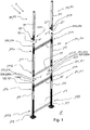
- FIG. 1 is a created from a scaffold system 1 scaffold 2 shown in exploded view.
- the scaffold system 1 or the scaffold 2 comprises a first scaffold component 101, which is designed as a first, lower scaffolding frame 102, which has a first, lower hollow profile rod 103 and a second, lower Hollow section bar 104 and the hollow profile bars 103, 104 connecting transverse struts 105, 106 includes.
- the hollow profile bars 103, 104 each have an upper tube section 103a, 104a and a lower tube section 103b, 104b.
- the lower frame component 102 further comprises built-in parts 121, 122, which are designed as tube connectors 123, 124.
- the pipe connector 123 is inserted into the upper pipe section 103a of the hollow profile 103, and in this case the pipe connector 124 is inserted into the upper pipe section 104a of the hollow profile 104, so that an upper plug-in pin 123a and an upper plug-in pin 124a respectively from the upper pipe sections 103a and 104a protrude.
- a threaded foot 107 and 108 is screwed, so that the lower frame member 101 can be placed on a substrate U.
- the scaffolding system 1 or the scaffold 2 also comprises a second scaffold component 201 which is designed as a second, upper scaffolding frame 202, which comprises a first, upper hollow profile rod 203 and a second, upper hollow profile rod 204 and transverse struts 205, 206 connecting the hollow profile rods 203, 204 includes.
- the hollow profile bars 203, 204 each have an upper tube section 203a, 204a and a lower tube section 203b, 204b.
- the upper frame component 202 further comprises mounting parts 221, 222, which are designed as reducing sleeves 223, 224.
- the Reduzierhülse 223 is inserted into the lower tube portion 203b of the hollow section 203 and in this case the Reduzierhülse 224 is inserted into the lower tube portion 204b of the hollow section 204, so that the Reduzierhülse 223 and 224 is received respectively in the lower tube sections 203b and 204b.
- the second scaffolding frame 202 For assembly, it is provided to place the second scaffolding frame 202 in the direction of the arrow z 'down on the lower scaffolding 102 so that the plug 123a is inserted into an interior 225b of a sleeve body 225 of the reducing sleeve 223 and that the plug 124a into an interior 226b a sleeve body 226 of the Reduction sleeve 224 is inserted, so that the frame members 101 and 201 are connected to each other.
- a third frame component 301 is shown, which is designed as a railing post 302, which comprises a hollow profile rod 303, a Reduzierhülse 323 and a screw lug 333.
- the reducing sleeve 323 is received in a lower tube portion 303b of the hollow profile rod 303.
- the eyelet 333 is screwed through the hollow profile bar 303 in the Reduzierhülse 323.
- a fourth frame member 401 is shown, which is designed as a railing post 402, which comprises a hollow profile bar 403, a Reduzierhülse 423 and a screw 433.
- the reducing sleeve 423 is received in a lower pipe section 403b of the hollow profile bar 403.
- the eyelet 433 is screwed through the hollow profile bar 403 in the Reduzierhülse 423.
- the upper scaffolding frame 202 comprises, as further built-in parts 231, 232, two pipe connectors 233, 234 which are inserted into the upper pipe sections 203a, 204a of the scaffolding frame 202.
- this pipe connector 233, 234 can be the railing posts 302 and 402 plug in the direction of other arrows z '.
- the framework 2 can be completed by scaffolding floors not shown and railing struts, not shown, and other scaffolding frames and railing posts.
- FIG. 2a shows a side view of the second, upper scaffolding frame 202 of the in FIG. 1 shown framework 2.
- the scaffolding frame 202 in the region of the upper tube portion 204 a of its second profile bar 204 is shown enlarged.
- a side view of the scaffolding frame 202 in the region of the upper tube portion 203 a of its first profile bar 203 is shown in section.
- This Detail is in the Figure 2c shown enlarged.
- the pipe connector 233 inserted into the upper pipe section 203a can be seen both with its upper plug-in pin 233a and with its lower plug-in pin 233b.
- the pipe connector 233 is inserted with its lower plug pin 233b in a cavity H203a of the upper pipe section 203a and protrudes with its upper plug pin 233a on the hollow profile rod 203 addition.
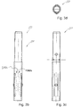
- FIGS. 3a to 3d the pipe connector 233 is shown in four views, wherein the pipe connector 233 is described by way of example for all on hollow profile bars of the scaffolding frames 102, 202 built-pipe connector.
- the pipe connector 233 is in perspective view ( FIG. 3a ), in side view in the direction of arrow y ( FIG. 3b ) and in side view in the direction of arrow x ( Figure 3c ), as well as in plan view in the direction of the arrow z '( 3d figure ).
- the pipe connector 233 comprises a double sleeve 241.
- This double sleeve 241 comprises the upper plug pin 233a and the lower plug pin 233b.
- the lower plug-in pin 233b has a first cylindrical outer circumferential surface AMF233b with a first outer diameter D233b
- the upper plug-in pin 233a has a second cylindrical outer circumferential surface AMF233a with a second outer diameter D233a.
- the lower plug-in pin 233b comprises a first latching device 242 and a second latching device 243, wherein the latching devices 242, 243 each comprise a latching lug 242a, 243a and a spring 242b, 243b, wherein each latching lug 242a, 243a in a latching position R242a, R243a, in which this is shown in the previously mentioned figures, protrudes outwardly beyond the first outer circumferential surface AMF233b.
- the locking lugs 242a, 243a by means of springs 242b, 243b so sprung on the first, lower plug pin 234b arranged that this from the rest position R242a, R243a so far against a restoring force of the respective spring 242b and 243b in the first plug pin 234b inside in a release position F242a, F243a (in FIG. 3b schematically indicated by dashed lines) can be pressed, that the locking lugs 242a, 243a are substantially flat in the first outer circumferential surface AMF233b.
- an outer diameter D233b of the lower spigot 233b is made larger than an outer diameter D233a of the upper spigot 233a, so that at a uniform inner diameter d203 (see FIG Figure 2c ) of the first hollow profile bar 203 and the same design of the other hollow profile bars of the first and second scaffolding frame or the railing post between the upper plug pin 233 a and the corresponding to the FIG. 1 on this plugged hollow profile bar 303 space for the Reduzierhülse 323 remains. From a comparative analysis of the FIGS.
- the pipe connector 233 engages with its detents 242a, 243a in opposite bores of the upper pipe section 203a of the hollow profile rod 203, when it is inserted with a corresponding orientation in the hollow profile rod 203.
- the scaffolding frame 202 is shown in a sectional view, so that the holes arranged in the upper tube section 203a of the hollow profile rod 203 are not visible.
- the hollow profile bar 204 formed comparable to the hollow profile rod 203 shown in side view, in this illustration, at the upper tube portion 204a with a bore B1-204a such a hole visible.
- a second bore B2-204a is hidden from the bore B1-204a.
- the upper tube portion 203a of the hollow profile rod 203 is formed identical with respect to these holes. Also, the hollow profile bars 103 and 104 of the lower scaffolding frame 102 (see FIG. 1 ) are identical with respect to the holes for engaging the pipe connectors 123, 124.
- a loosening of the pipe connector 233 from the hollow profile rod 203 is possible in that both locking lugs 242a, 243a are pressed in at the same time and the pipe connector 233 is pulled out of the hollow profile rod 203.
- the spring 242b of Locking device 242 is formed by a latching portion 251 of the lower plug 233b of the double sleeve 241, which longitudinally by axially in the direction of a longitudinal axis L233 of the pipe connector 233 adjacent cuts 251a, 251b of a holding portion 252 of the lower plug pin 233b is separated and transverse to the holding portion 252nd of the lower spigot 233b is connected.
- the locking lug 242a is connected to the latching portion 251.
- the latching section 251 forms a leaf spring clamped on both sides, the clamping being effected by a direct connection to the holding section 252.
- the pipe connector 233 is formed as a plastic component, wherein the holding portion 252 and the locking portion 251 of the same material, and are integrally formed.
- the second latching device 243 of the lower plug pin 233b of the double sleeve 241 is analogous to the first latching device 242 and this formed opposite.
- the other previously mentioned pipe connectors are each formed with two such locking devices. Accordingly, the upper pipe sections of all other hollow profile bars of scaffolding frames are formed with holes.
- the lower plug pin 233b and the upper plug pin 233a of the double sleeve 241 are each formed as a tubular plug-in pin with a cylindrical interior.
- the lower spigot and the upper spigot of the double sleeve are each formed as a pin-like spigot made of solid material.
- These pin-like plug-in pins then have recesses in the region of the latching devices, so that the latching sections can deflect in the direction of the longitudinal axis of the pipe connector.
- FIG. 4a shows again from the FIG. 2a known side view of the second, upper scaffolding frame 202 of the in the FIG. 1 shown framework 2.
- the scaffolding frame 202 in the region of the lower tube section 204b his second profile bar 204 shown enlarged.
- the scaffolding frame 202 is shown in section in the region of the lower tube section 203b of its first profile bar 203.
- This detail is in the Figure 4c shown enlarged.
- the inserted into the lower pipe section 203b Reduzierhülse 223 can be seen.
- the reducing sleeve 223 is received in a cavity H203b of the lower tube portion 203b.
- the Reduzierhülse 223 is shown in four views, wherein the Reduzierhülse 223 is described by way of example for all on hollow profile bars of the scaffolding frames 202, 203 Reduzierhülsen.
- the reducing sleeve 223 is in perspective view ( FIG. 5a ), in side view in the direction of arrow y ( FIG. 5b ) and in side view in the direction of arrow x ( FIG. 5c ), as well as in plan view in the direction of the arrow z '( FIG. 5d ).
- the reducing sleeve 223 comprises the sleeve body 225, which comprises a cylindrical outer circumferential surface AMF225. Furthermore, the reducing sleeve 223 comprises a first latching device 262 and a second latching device 263, wherein the latching devices 262, 263 each comprise a latching lug 262a, 263a and a spring 262b, 263b and wherein the latching lug 262a, 263a in a latching position R262a or R263a to the outside projecting beyond the outer circumferential surface AMF225 and being suspended from the sleeve body 225 in such a manner that they are displaced from the rest position R262a or R263a against a restoring force of the spring 262b, 263b into a release position F262a, F263a, with dashed lines schematically in FIG FIG. 5b indicated in the sleeve body 225 are pressed, that the locking lugs 262a, 263a
- the sleeve body 225 also includes a cylindrical inner circumferential surface IMF225, wherein the latching device 262 is designed such that the latching device 262 in the latching position R262a outside of the inner circumferential surface IMF225 defined interior 225b of the sleeve body 225 is located.
- the locking lugs 262a, 263a are formed as a cylinder. According to embodiments not shown here, it is provided to form at least one locking lug as a circular ring or as a threaded nut.
- the spring 262b of the reducing sleeve 223 is formed by a latching portion 271 of the sleeve body 225 of the reducing sleeve 223 which is longitudinally separated from a holding portion 272 of the sleeve body 225 by cuts 271a, 271b extending alongside one another in the direction of a longitudinal axis L223 of the reducing sleeve 223 is and is connected to the transverse side with the holding portion 272 of the sleeve body 225.
- the locking lug 262a is connected to the latching portion 271.
- the latching portion 271 forms a leaf spring clamped on both sides, the clamping being realized by a direct connection to the holding portion 272.
- the Reduzierhülse 223 is formed as a plastic component, wherein the holding portion 272 and the locking portion 271 of the same material, and are integrally formed.
- the second latching device 263 of the sleeve body 225 is formed analogously to the first latching device 262 and this opposite.
- the other Reduzierhülsen so far mentioned are each formed with two such locking devices.
- FIGS. 4a to 4c 5a to 5d From a comparative analysis of the FIGS. 4a to 4c 5a to 5d it can be seen that the reduction sleeve 223 with its locking lugs 262a, 263a engages in opposite bores of the lower tube section 203b of the hollow profile rod 203, when it is inserted with a corresponding orientation from below into the hollow profile rod 203.
- the scaffolding frame 202 is shown in a sectional view, so that the holes arranged in the lower tube section 203b of the hollow profile rod 203 are not visible.
- the hollow profile bar 204 formed comparable to the hollow profile bar 203 shown in side view, in this illustration is at its lower tube portion 204 b with a Bore B1-204b such a hole visible.
- a second hole B2-204b is hidden from the bore B1-204b.
- the lower tube portion 203b of the hollow profile rod 203 is formed identical with respect to these holes.
- the hollow profile bars 103 and 104 of the lower scaffolding frame 102 are identical with respect to the holes for engaging the Reduzierhülsen.
- the one in the FIG. 4b Hollow section bar 204 shown yet two more, opposite holes B3-204b and B4-204b, which correspond with inserted reducing sleeve 224 with further holes of the Reduzierhülse 224. These holes are exemplified on the identical executed and in the FIG. 5a shown reducing sleeve 223 and exemplified with B3-223 and B4-223.
- the hollow profile bars 303, 403 of the railing posts 302, 402 (see FIG. 1 ) have holes into which the Reduzierhülse 323 and 423 engages.
- the hollow profile bars 303, 402 of the glazing posts 302, 402 have bores.
- the Figures 6a and 6b a side view and a sectional side view of the lower pipe section 303b of the railing post 302 formed third scaffolding member 301 shown in an enlarged view.
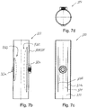
- the Reduzierhülse 323 is installed in the railing post 302. This differs from the built in the scaffolding frame reducer and is in the FIGS. 7a to 7d shown as a single component in various views, the Reduzierhülse 323 is described as an example of all installed on hollow profile bars of railing posts Reduzierhülsen.
- the Reduzierhülse 323 is in perspective view ( Figure 7a ), in side view in the direction of arrow y ( FIG. 7b ) and in side view in the direction of arrow x ( FIG. 7c ), as well as in plan view in the direction of the arrow z '( FIG. 7d ).
- the reducing sleeve 323 comprises a sleeve body 325, which comprises a cylindrical outer circumferential surface AMF325. Furthermore, the reduction sleeve 323 comprises a first latching device 362 and a second latching device 363, wherein the latching devices 362, 363 each comprise a latching lug 362a, 363a and a spring 362b, 363b and wherein the latching lug 362a, 363a in a latching position R362a or R363a to the outside protrude over the outer circumferential surface AMF325 and are so sprung on the sleeve body 325 are arranged so that this from the rest position R362a or R363a so far against a restoring force of the spring 362b, 363b in release positions F362a, F363a, with dashed lines schematically in the FIG. 7b indicated in the sleeve body 325 are pressed, that the locking lugs 362a, 363a
- the sleeve body 325 also comprises a cylindrical inner circumferential surface IMF325, wherein the latching device 362 is configured such that the latching device 362 lies in the latching position R362a outside an interior 325b of the sleeve body 325 defined by the inner circumferential surface IMF325.
- the locking lug 362a is designed as a threaded nut GWM362a.
- the detent 363a is formed as a cylinder.
- the spring 362b the Reduzierhülse 323 is formed by a latching portion 371 of the sleeve body 325 of the Reduzierhülse 323, which is longitudinally separated by axially in the direction of a longitudinal axis L323 of Reduzierhülse 323 adjacent cuts 371 a, 371 b of a holding portion 372 of the sleeve body 325 and the transverse side with the holding portion 372 of Sleeve body 325 is connected.
- the detent 362a is connected to the latching portion 371.
- the latching section 371 forms a leaf spring clamped on both sides, the clamping being realized by a direct connection to the holding section 372.
- the Reduzierhülse 323 is formed as a plastic component, wherein the holding portion 372 and the locking portion 371 of the same material, and are integrally formed.
- the second latching device 363 of the sleeve body 325 is formed analogously to the first latching device 362 and this opposite, wherein the first latching device 362 is dimensioned larger than the second latching device 363. This makes it possible that the latching portion 371 can be elastically deformed so far that the comparatively large-dimensioned threaded nut GWM362a lies flat in the outer circumferential surface AMF325, so that the reducing sleeve 323 can be inserted and ejected into the tread bar 303.
- the hollow profile rod 303 comprises at its lower tube section 303b a first bore B1-303b, which is adapted in its diameter to the latching lug 362a designed as a threaded nut GWM362a, and a second bore B2-303b, which has a diameter corresponding to the second cylinder Latch 363a is adapted (see FIGS. 6a, 6b ).
- the two bores B1-303b and B2-303b lie on a common longitudinal axis L303b, which orthogonally intersects the longitudinal axis L323 of the reducing sleeve 323.
- FIG. 1 Known screw eye 333 shown, which is screwed into the protruding from the bore B1-303b threaded nut GWM362a the Reduzierhülse 323.
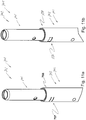
- FIGS. 8a to 8d is a third embodiment a Reduzierhülse 523 in perspective view ( FIG. 8a ), in side view in the direction of arrow y ( FIG. 8b ) and in side view in the direction of arrow x ( FIG. 8c ), as well as in plan view in the direction of the arrow z '( FIG. 8d ).
- the reducing sleeve 523 differs from that in the FIGS. 5a to 5d shown reducing sleeve 223 in that it has no holes B3-223 and B4-223 in addition to the locking lugs.
- the locking lugs 562a, 563a are not formed as cylinders, but as circular rings K562a or K563a.
- a safety bolt through the circular rings K562a, K563a and associated through these holes in a suitable for the Reduzierhülse 523, not shown hollow profile bar are inserted.
- FIGS. 9a to 9c a second embodiment of a pipe connector 601 is shown in three perspective views.
- the pipe connector 601 is formed in two parts or two layers and comprises, in addition to a double sleeve 602, in particular designed as a one-piece plastic component (see FIG. 9a ) a core sleeve 603 (see FIG. 9b ), which is designed in particular as a metal sleeve.
- the double sleeve 602 is formed as an outer sleeve.
- the core sleeve 603 is formed as an inner sleeve.
- the core sleeve 603 has a length L603 which corresponds approximately to a length L602 of the double sleeve 602.
- the complete pipe connector 601 is shown as a transparent component.
- the core sleeve 603 is inserted as an inner sleeve in the double sleeve 602, which forms an outer sleeve.
- the two sleeves 602, 603 are frictionally connected with each other.
- a variant of the invention provides that these are additionally or alternatively also glued together and / or positively connected.
- the double sleeve 602 is basically analogous to the particular in the FIG.
- two opposing receptacles 681, 682 are formed on a lower plug-in pin 233b above the latching devices 642, 643, which form recesses or depressions or openings on an outer casing surface AMF633b of the lower plug-in pin 633b.
- the core sleeve 603 comprises in the region of each latching device 642, 643 of the double sleeve 602 a notch 691, 692, wherein the notches 691, 692 are dimensioned such that each latching device 642, 643 in the direction of a longitudinal axis L601 of the pipe connector 601 undisturbed by the core sleeve 603 deformable is. Furthermore, the core sleeve 603 in the region of each bore B3-633a, B4-633a of the double sleeve 602 includes a further notch 693, 694, wherein the notches 693, 694 are each formed as a through hole.
- the core sleeve 603 also has notches 602 in the region of the recesses 681, 682 of the double sleeve 602.
- FIG. 10a and 10b a variant embodiment of a scaffolding frame 702 in the region of an upper tube section 703a of one of its hollow profile bars 703 is shown in perspective and transparent perspective view.
- the scaffolding frame 702 is basically designed in accordance with the above-described scaffolding frames 102 and 202 and has, in particular, bores B1-703a and B2-703a into which the scaffolding in the FIG. 9c shown raw connector 601 can be engaged with its locking lugs 642a, 643a, so that its receptacles 681, 682 are aligned on formed on the upper pipe section 703a forming sections 797, 798.
- the forming sections 797, 798 are formed by opposing and radially extending dividing slots 797a, 797b and 798a, 798b, which sever the upper tube section 703a. Through these radial separating slots 797a, 797b and 798a, 798b, respectively, the forming sections 797, 798 are annular-section-like (see FIG FIG. 10a ). Thus, the upper pipe section 703a can be plastically deformed in the region thereof by a pressing force and thereby pressed flat, that the forming section 797, 798 in the formed state (see FIG.
- a scaffold component such as scaffolding frame 702 is then manufactured such that first opposing and radially extending separating slots are introduced at an upper tube portion of the hollow profile rod of the scaffold component, wherein the upper tube section is severed by the separating slots, and a particular annular ring-like forming section is formed, that then the pipe connector in the end opening of the hollow profile bars are inserted such that latching devices of the pipe connector with locking lugs in holes of the hollow profile bars latched and that then a plastic impressions of the Umformabête takes place such that the deformed jacket portions protrude into cavities of the upper pipe sections and in the recess of the pipe connector.
- FIGS. 10a, 10b show analogous to the FIGS. 10a, 10b a section of a scaffolding component 701, which is completed by the inserted tube connector 601 and designed as scaffolding frames 702, in the case of undeformed forming sections 797, 798 (FIG. FIG. 11a ) and deformed forming sections 797, 798.
Landscapes
- Engineering & Computer Science (AREA)
- Architecture (AREA)
- Mechanical Engineering (AREA)
- Civil Engineering (AREA)
- Structural Engineering (AREA)
- Mutual Connection Of Rods And Tubes (AREA)
Abstract
Die Erfindung betrifft ein Verbindungssystem umfassend wenigstens ein erstes Einbauteil (121; 122) und wenigstens ein zweites Einbauteil (221; 222), wobei das Verbindungssystem zur Verbindung eines ersten Gerüstrahmens (102), welcher wenigstens einen Hohlprofilstab (103; 104) umfasst, und eines zweiten Gerüstrahmens (202), welcher wenigstens einen Hohlprofilstab (203; 204) umfasst, vorgesehen ist. Hierbei ist das erste Einbauteil (121; 122) als Rohrverbinder (123, 124) ausgebildet und in das untere Gerüstbauteil (101) einbaubar, hierbei ist das zweite Einbauteil (221; 222) als Reduzierhülse (223, 224) ausgebildet ist und in das obere Gerüstbauteil (201) einbaubar und hierbei ist der Rohrverbinder (123, 124) in die Reduzierhülse (223, 224) einsteckbar.The invention relates to a connection system comprising at least one first installation part (121; 122) and at least one second installation part (221; 222), the connection system for connecting a first scaffolding frame (102) comprising at least one hollow profile rod (103; 104), and a second scaffolding frame (202), which comprises at least one hollow profile rod (203, 204) is provided. In this case, the first built-in part (121, 122) is designed as a pipe connector (123, 124) and can be installed in the lower frame component (101), in which case the second built-in part (221, 222) is designed as a reducing sleeve (223, 224) and into which Upper scaffold component (201) can be installed and in this case the pipe connector (123, 124) in the Reduzierhülse (223, 224) can be inserted.
Description
Die Erfindung betrifft eine Reduzierhülse, einen Rohrverbinder, ein Verbindungssystem, ein Gerüstbauteil, ein Gerüstsystem sowie ein Verfahren zur Herstellung eines Gerüstbauteils gemäß dem Oberbegriff des Anspruchs 1 bzw. 6 bzw. 13 bzw. 14 bzw. 15 bzw. 21.The invention relates to a reducing sleeve, a pipe connector, a connection system, a scaffolding component, a scaffolding system and a method for producing a scaffold component according to the preamble of
Aus der
Es ist Aufgabe der Erfindung, eine Reduzierhülse, einen Rohrverbinder, ein Verbindungssystem, ein Gerüstbauteil, ein Gerüstsystem bzw. ein Verfahren zur Herstellung eines Gerüstbauteils vorzuschlagen durch welchen bzw. welches sich leichte und stabile Gerüste einfach herstellen lassen, welche insbesondere bei Verschleiß auch kostengünstig aufbereitet werden können.It is an object of the invention to provide a Reduzierhülse, a pipe connector, a connection system, a scaffolding component, a scaffold system or a method for producing a scaffold component by which or which can be easily produced and stable scaffolds, which also processed at low cost and cost can be.
Diese Aufgabe wird ausgehend von den Merkmalen des Oberbegriffs des Anspruchs 1 bzw. 6 bzw. 13 bzw. 14 bzw. 15 bzw. 21 durch die kennzeichnenden Merkmale des Anspruchs 1 bzw. 6 bzw. 13 bzw. 14 bzw. 15 bzw. 21 gelöst. In den ggf. vorhandenen Unteransprüchen sind vorteilhafte und zweckmäßige Weiterbildungen angegeben.This object is achieved on the basis of the features of the preamble of
Die erfindungsgemäße Reduzierhülse, welche zum Einbau in ein Gerüstbauteil, insbesondere in einen Hohlprofilstab und vorzugsweise in einen Gerüstrahmen, welcher wenigstens einen Hohlprofilstab umfasst, vorgesehen ist, umfasst einen Hülsenkörper mit einer zylindrischen Außenmantelfläche, wobei die Reduzierhülse wenigstens eine Rasteinrichtung umfasst, wobei die Rasteinrichtung eine Rastnase und eine Feder umfasst, wobei die Rastnase in einer Raststellung nach außen über die Außenmantelfläche übersteht und derart gefedert an dem Hülsenkörper angeordnet ist, dass diese aus der Raststellung derart weit gegen eine Rückstellkraft der Feder in den Hülsenkörper eindrückbar ist, dass die Rastnase im Wesentlichen plan in der Außenmantelfläche liegt. Eine derartige Reduzierhülse lässt sich schnell und einfach an einem mit einer bzw. mehreren entsprechend angeordneten Bohrungen versehenen Gerüstbauteil befestigen, ohne das weitere Fertigungsschritte zur Verbindung der Reduzierhülse und des Gerüstbauteils erfolgen müssen. Weiterhin ist auch problemlos eine Demontage der Reduzierhülse von dem Gerüstbauteil durch ein Lösen der Rastverbindung bzw. der Rastverbindungen möglich, so dass die verbaute Reduzierhülse bei Verschleiß schnell durch eine neue Reduzierhülse ersetzt werden kann.The reducing sleeve according to the invention, which is intended for installation in a scaffold component, in particular in a hollow profile rod and preferably in a scaffolding frame, which comprises at least one hollow profile rod, comprises a sleeve body with a cylindrical outer circumferential surface, wherein the Reduzierhülse comprises at least one latching device, wherein the latching means a Latching nose and a spring comprises, wherein the locking lug protrudes in a detent position to the outside over the outer circumferential surface and is sprung on the sleeve body is arranged so that from the detent position against the restoring force of the spring in the sleeve body can be pressed so far that the latch substantially plan lies in the outer circumferential surface. Such a reduction sleeve can be fastened quickly and easily to a scaffold component provided with one or more appropriately arranged bores, without having to carry out further manufacturing steps for connecting the reducing sleeve and the scaffolding component. Furthermore, a dismantling of the Reduzierhülse of the scaffold component by releasing the locking connection or the locking connections is also possible without any problems, so that the built-Reduzierhülse can be quickly replaced by a new Reduzierhülse when worn.
Weiterhin ist es bevorzugt vorgesehen, dass der Hülsenkörper eine zylindrische Innenmantelfläche aufweist, wobei die Rasteinrichtung derart ausgebildet ist, dass diese in der Raststellung außerhalb eines durch die Innenmantelfläche definierten Innenraums des Hülsenkörpers liegt, wobei die Rastnase insbesondere als Zylinder oder als Kreisring oder als Gewindemutter ausgebildet ist. Hierdurch ist es möglich, ein zylindrisches Bauteil in den Hülsenkörper einzuschieben, ohne dass das Einschieben durch die Rasteinrichtung behindert wird.Furthermore, it is preferably provided that the sleeve body has a cylindrical inner circumferential surface, wherein the latching device is designed such that it lies in the detent position outside an interior of the sleeve body defined by the inner circumferential surface, wherein the detent formed in particular as a cylinder or as a circular ring or as a threaded nut is. This makes it possible to insert a cylindrical component in the sleeve body, without the insertion is hindered by the locking device.
Es ist auch vorgesehen, dass die Feder der Rasteinrichtung durch einen ersten Rastabschnitt des Hülsenkörpers gebildet ist, welcher längsseitig durch axial in Richtung einer Längsachse des Hülsenkörpers nebeneinander verlaufende Schnitte von einem Halteabschnitt des Hülsenkörpers getrennt ist und querseitig mit dem Halteabschitt des Hülsenkörpers verbunden ist, wobei die Rastnase mit dem Rastabschnitt verbunden ist. Hierdurch lässt sich die Reduzierhülse einfach herstellen und als einteiliges, sortenreines und damit einfach recyclebares Bauteil realisieren.It is also envisaged that the spring of the latching device is formed by a first latching portion of the sleeve body, which longitudinally side by side extending axially in the direction of a longitudinal axis of the sleeve body Slices is separated from a holding portion of the sleeve body and is connected transversely with the Halteeabschitt of the sleeve body, wherein the latching lug is connected to the latching portion. As a result, the Reduzierhülse can be easily manufactured and realized as a one-piece, unmixed and therefore easily recyclable component.
Es ist auch vorgesehen, dass die Reduzierhülse wenigstens eine weitere, zweite Rasteinrichtung umfasst, wobei die erste und die zweite Rasteinrichtung gegenüberliegend angeordnet sind und dass die Reduzierhülse insbesondere wenigstens eine erste Bohrung und vorzugsweise wenigstens eine weitere, zweite Bohrung umfasst, wobei die erste und die zweite Bohrung insbesondere gegenüberliegend angeordnet sind. Durch eine zweite, gegenüberliegend angeordnete Rasteinrichtung lässt sich ein stabiler Sitz der Reduzierhülse in einem Hohlprofil gewährleisten.It is also contemplated that the Reduzierhülse comprises at least one further, second latching device, wherein the first and the second latching means are arranged opposite and in that the Reduzierhülse in particular at least a first bore and preferably at least one further, second bore, wherein the first and the second bore are arranged in particular opposite one another. By a second, oppositely arranged locking device can ensure a stable fit of the Reduzierhülse in a hollow profile.
Schließlich ist es vorgesehen, dass die Reduzierhülse als insbesondere einteiliges Bauteil und vorzugsweise als einteiliges Kunststoffbauteil ausgebildet ist. Hierdurch lässt sich die Reduzierhülse einfach herstellen und als einteiliges, sortenreines und damit einfach recyclebares Bauteil realisieren.Finally, it is provided that the Reduzierhülse is designed as a particular one-piece component and preferably as a one-piece plastic component. As a result, the Reduzierhülse can be easily manufactured and realized as a one-piece, unmixed and therefore easily recyclable component.
Es ist vorgesehen, dass der erfindungsgemäße Rohrverbinder zum Einbau in ein Gerüstbauteil, insbesondere in einen Hohlprofilstab und vorzugsweise in einen Gerüstrahmen, welcher wenigsten einen Hohlprofilstab umfasst, eine Doppelhülse umfasst, dass die Doppelhülse einen ersten, unteren Steckzapfen mit einer ersten zylindrischen Außenmantelfläche mit einem ersten Außendurchmesser umfasst und dass die Doppelhülse einen zweiten, oberen Steckzapfen mit einer zweiten zylindrischen Außenmantelfläche mit einem zweiten Außendurchmesser umfasst, dass der erste, untere Steckzapfen wenigstens eine Rasteinrichtung umfasst, wobei die Rasteinrichtung eine Rastnase und eine Feder umfasst, wobei die Rastnase in einer Raststellung nach außen über die erste Außenmantelfläche übersteht und derart gefedert an dem ersten, unteren Steckzapfen angeordnet ist, dass diese aus der Raststellung derart weit gegen eine Rückstellkraft der Feder in den ersten Steckzapfen eindrückbar ist, dass die Rastnase im Wesentlichen plan in der ersten Außenmantelfläche liegt und dass der erste, untere Steckzapfen einen Außendurchmesser aufweist, welcher größer ist als ein Außendurchmesser des zweiten, oberen Steckzapfens. Ein derartiger Rohrverbinder lässt sich schnell und einfach an einem mit einer bzw. mehreren entsprechend angeordneten Bohrungen versehenen Gerüstbauteil befestigen, ohne das weitere Fertigungsschritte zur Verbindung des Rohrverbinders und des Gerüstbauteils erfolgen müssen. Weiterhin ist auch problemlos eine Demontage des Rohrverbinders von dem Gerüstbauteil durch ein Lösen der Rastverbindung bzw. der Rastverbindungen möglich, so dass der verbaute Rohrverbinder bei Verschleiß schnell durch einen neuen Rohrverbinder ersetzt werden kann.It is envisaged that the pipe connector according to the invention for installation in a scaffold component, in particular in a hollow profile bar and preferably in a scaffolding, which comprises at least one hollow profile bar, a double sleeve, that the double sleeve has a first, lower plug with a first cylindrical outer surface with a first Outer diameter and that the double sleeve comprises a second, upper plug with a second cylindrical outer surface having a second outer diameter, that the first, lower plug pin comprises at least one latching device, wherein the latching device comprises a latching nose and a spring, wherein the latching lug in a latching position after outside over the first Outer shell surface protrudes and is so sprung on the first, lower plug pin is arranged, that it is so far pressed against the restoring force of the spring in the first plug-in pin from the detent position, that the detent is substantially flat in the first outer circumferential surface and that the first, lower Plug-in pin has an outer diameter which is larger than an outer diameter of the second, upper spigot. Such a pipe connector can be quickly and easily attached to a provided with one or more appropriately arranged holes scaffold component, without the need further manufacturing steps to connect the pipe connector and the scaffold component. Furthermore, a dismantling of the pipe connector from the scaffold component by releasing the locking connection or the snap-in connections is also possible without any problems, so that the installed pipe connector can be quickly replaced by a new pipe connector when worn.
Es ist auch vorgesehen, dass die Feder der Rasteinrichtung durch einen Rastabschnitt des unteren Steckzapfens der Doppelhülse gebildet ist, welcher längsseitig durch axial in Richtung einer Längsachse des Rohrverbinders nebeneinander verlaufende Schnitte von einem Halteabschnitt des unteren Steckzapfens getrennt ist und querseitig mit dem Halteabschnitt des unteren Steckzapfens verbunden ist, wobei die Rastnase mit dem Rastabschnitt verbunden ist. Hierdurch lässt sich der Rohrverbinder einfach herstellen und als einteiliges, sortenreines und damit einfach recyclebares Bauteil realisieren.It is also envisaged that the spring of the latching device is formed by a latching portion of the lower spigot of the double sleeve, which is longitudinally separated by axially extending in the direction of a longitudinal axis of the pipe connector sections of a holding portion of the lower spigot and the transverse side with the holding portion of the lower spigot is connected, wherein the latching nose is connected to the latching portion. As a result, the pipe connector can be easily produced and realized as a one-piece, unmixed and thus easily recyclable component.
Weiterhin ist es vorgesehen, dass der erste, untere Steckzapfen der Doppelhülse wenigstens eine weitere, zweite Rasteinrichtung umfasst, wobei die erste und die zweite Rasteinrichtung gegenüberliegend angeordnet sind und dass der zweite, obere Steckzapfen des Rohrverbinders insbesondere wenigstens eine erste Bohrung und vorzugsweise wenigstens eine weitere, zweite Bohrung umfasst, wobei die erste und die zweite Bohrung insbesondere gegenüberliegend angeordnet sind. Durch eine zweite, gegenüberliegend angeordnete Rasteinrichtung lässt sich ein stabiler Sitz des Rohrverbinders in einem Hohlprofil gewährleisten.Furthermore, it is provided that the first, lower plug-in pin of the double sleeve comprises at least one further, second latching device, wherein the first and the second latching device are arranged opposite one another and that the second, upper plug-in pin of the pipe connector in particular at least one first bore and preferably at least one further , Second bore, wherein the first and the second bore are arranged in particular opposite. By a second, oppositely arranged locking device can ensure a stable fit of the pipe connector in a hollow profile.
Es ist auch vorgesehen, dass der erste, untere Steckzapfen der Doppelhülse als rohrartiger Steckzapfen mit einem zylindrischen Innenraum oder als dornartiger Steckzapfen aus Vollmaterial ausgebildet ist und dass der zweite, obere Steckzapfen des Rohrverbinders als rohrartiger Steckzapfen mit einem zylindrischen Innenraum oder als dornartiger Steckzapfen aus Vollmaterial ausgebildet ist. Durch dornartige, aus Vollmaterial gebildete Steckzapfen lassen sich unter Inkaufnahme eines höheren Materialaufwands auf einfache Weise stabile Rohrverbinder herstellen. Rohrartig ausgebildete Steckzapfen haben den Vorteil, dass diese ein geringes Gewicht aufweisen und dass durch diese die Hohlprofile nicht verschlossen werden, so dass eindringendes Wasser problemfrei ablaufen kann.It is also envisaged that the first lower spigot of the double sleeve is formed as a tube-like spigot with a cylindrical interior or pin-like spigot made of solid material and that the second, upper spigot of the pipe connector as a tubular spigot with a cylindrical interior or as a pin-like spigot made of solid material is trained. By thorn-like, formed of solid material journals can be produced at a cost of a higher material cost in a simple way stable pipe connector. Pipe-shaped plug-in pins have the advantage that they have a low weight and that the hollow sections are not closed by this, so that penetrating water can proceed without problems.
Weiterhin ist es vorgesehen, dass der erste, untere Steckzapfen der Doppelhülse an seiner Außenmantelfläche und insbesondere oberhalb der Rasteinrichtung wenigstens eine als Einformung, Vertiefung oder Durchbruch ausgebildete Aufnahme aufweist und insbesondere zwei sich gegenüberliegende Aufnahmen umfasst. Hierdurch lässt sich ergänzend zu der Rastverbindung eine weitere, insbesondere formschlüssige Verbindung zwischen dem Hohlprofil und Rohrverbinder schaffenFurthermore, it is provided that the first, lower plug-in pin of the double sleeve has on its outer circumferential surface and in particular above the latching device at least one receptacle formed as a recess, depression or aperture and in particular comprises two opposing receptacles. As a result, a further, in particular positive connection between the hollow profile and pipe connector can be created in addition to the latching connection
Es ist auch vorgesehen, dass die Doppelhülse entweder als insbesondere einteiliges Bauteil und vorzugsweise einteiliges Kunststoffbauteil ausgebildet ist oder dass der Rohrverbinder zusätzlich zu der insbesondere als einteiliges Bauteil, vorzugsweise einteiliges Kunststoffbauteil ausgeführten Doppelhülse eine Kernhülse umfasst, wobei sich die Kernhülse mit ihrer Länge insbesondere über eine Länge der Doppelhülse erstreckt, wobei die Kernhülse insbesondere als Metallhülse ausgebildet ist, wobei die Kernhülse insbesondere reibschlüssig mit der eine Außenhülse bildenden Doppelhülse verbunden ist. Durch eine einteile Ausführung ist die Herstellung vereinfacht und ist der Rohrverbinder als einteiliges, sortenreines Bauteil einfach recyclebar. Durch eine zweiteilige bzw. zweischichtige Ausbildung des Rohrverbinders entsteht durch dessen vorzugsweise metallische Kernhülse eine besonderes stabiler Rohrverbinder und durch dessen den Außenmantel bildende Doppelhülse aus Kunststoff ein durch die guten Gleiteigenschaften von Kunststoff einfach handhabbares Bauteil.It is also contemplated that the double sleeve is formed either as a particular one-piece component and preferably one-piece plastic component or that the pipe connector in addition to the executed in particular as a one-piece component, preferably one-piece plastic component double sleeve comprises a core sleeve, wherein the core sleeve with its length in particular via a Length of the double sleeve extends, the core sleeve is in particular designed as a metal sleeve, wherein the core sleeve in particular frictionally with the outer sleeve forming a double sleeve connected is. By a one-piece design, the production is simplified and the pipe connector is easily recyclable as a one-piece, unmixed component. By a two-part or two-layer design of the pipe connector is formed by the preferably metallic core sleeve, a special stable pipe connector and the outer shell forming double sleeve made of plastic by the good sliding properties of plastic easily manageable component.
Schließlich ist es vorgesehen, dass die Kernhülse im Bereich jeder Rasteinrichtung der Doppelhülse eine Ausklinkung aufweist, wobei die Ausklinkung derart bemessen ist, dass die Rasteinrichtung in Richtung einer Längsachse des Rohrverbinders verformbar ist und dass es insbesondere vorgesehen ist, dass die Kernhülse im Bereich jeder Bohrung der Doppelhülse eine weitere Ausklinkung aufweist, wobei die weitere Ausklinkung vorzugsweise als Durchgangsbohrung oder als Gewindebohrung ausgebildet ist. Hierdurch behält der zweischichtige Rohrverbinder trotz seiner stabilisierenden Innenhülse sämtliche Vorteile, welche der einteilige Rohrverbinder in Bezug auf einfache Herstellbarkeit und Vielseitigkeit aufweist.Finally, it is provided that the core sleeve in the region of each latching device of the double sleeve has a notch, wherein the notch is dimensioned such that the latching device is deformable in the direction of a longitudinal axis of the pipe connector and that it is provided in particular that the core sleeve in the region of each bore the double sleeve has a further notch, wherein the further notch is preferably formed as a through hole or a threaded bore. In this way, despite its stabilizing inner sleeve, the two-layer tube connector retains all the advantages that the one-piece tube connector has in terms of ease of manufacture and versatility.
Bei dem erfindungsgemäßen Verbindungssystem ist das erste Einbauteil als Rohrverbinder ausgebildet und in das untere Gerüstbauteil einbaubar, wobei weiterhin das zweite Einbauteil als Reduzierhülse ausgebildet ist und in das obere Gerüstbauteil einbaubar ist, wobei die Reduzierhülse insbesondere nach wenigstens einem der Ansprüche 1 bis 5 ausgebildet ist und wobei der Rohrverbinder insbesondere nach wenigstens einem der Ansprüche 6 bis 12 ausgebildet ist und dass der Rohrverbinder in die Reduzierhülse einsteckbar ist. Ein derartiges Verbindungssystem ist einfach in ein Gerüstsystem integrierbar, das sowohl die Einbauteile einfach herstellbar, bei einteiliger Ausführung leicht recyclebar und einfach montier und demontierbar sind.In the connection system according to the invention, the first built-in part is designed as a pipe connector and can be installed in the lower frame component, wherein furthermore the second built-in part is designed as Reduzierhülse and can be installed in the upper frame component, wherein the Reduzierhülse is formed in particular according to at least one of
Das erfindungsgemäße Gerüstbauteil, welches insbesondere einen Hohlprofilstab oder einen Gerüstrahmen mit wenigstens einem Hohlprofilstab umfasst ist dadurch gekennzeichnet, dass das Gerüstbauteil einen oberen Rohrabschnitt und einen unteren Rohrabschnitt umfasst, dass das Gerüstbauteil weiterhin eine Reduzierhülse nach wenigstens einem der Ansprüche 1 bis 5 umfasst und/oder dass das Gerüstbauteil einen Rohrverbinder nach wenigstens einem der Ansprüche 6 bis 12 umfasst, dass an dem oberen Rohrabschnitt wenigstens eine Bohrung angeordnet ist, in welche eine Rastnase des Rohrverbinders eingerastet ist und/oder dass an dem unteren Rohrabschnitt wenigstens eine Bohrung angeordnet ist, in welche eine Rastnase der Reduzierhülse eingerastet ist und dass es insbesondere auch vorgesehen ist, dass an dem oberen Rohrabschnitt durch sich gegenüberliegende und radial verlaufende Trennschlitze, welche den oberen Rohrabschnitt durchtrennen, ein insbesondere kreisringabschnittähnlicher Umformabschnitt ausgebildet ist, welcher durch eine Presskraft derart plastisch umgeformt und hierbei flach gedrückt ist, dass der umgeformte Umformabschnitt in einen Hohlraum des oberen Rohrabschnitts und eine Aufnahme der Reduzierhülse ragt. Derartige Gerüstbauteile lassen sich einfach herstellen und einfach mit derartig ausgebildeten anderen Gerüstbauteilen zusammenfügen und trennen.The scaffold component according to the invention, which comprises in particular a hollow profile rod or scaffolding frame with at least one hollow profile rod, is characterized in that the scaffold component comprises an upper tube section and a lower tube section, that the scaffold component further comprises a Reduzierhülse according to at least one of
Das erfindungsgemäße Gerüstsystem umfasst wenigsten ein erstes Gerüstbauteil, insbesondere einen Hohlprofilstab oder einen Gerüstrahmen mit wenigstens einem Hohlprofilstab und wenigstens ein zweites Gerüstbauteil, insbesondere einen Hohlprofilstab oder einen Gerüstrahmen mit wenigstens einem Hohlprofilstab, wobei das erste Gerüstbauteil wenigstens ein erstes Einbauteil umfasst, und wobei das zweite Gerüstbauteil wenigstens ein zweites Einbauteil umfasst, hierbei ist es vorgesehen, dass das zweite Einbauteil als Reduzierhülse ausgebildet ist und insbesondere nach wenigstens einem der Ansprüche 1 bis 5 ausgebildet ist und dass das erste Einbauteil als Rohrverbinder ausgebildet ist und insbesondere nach wenigstens einem der Ansprüche 6 bis 12 ausgebildet ist, dass der Rohrverbinder in einer endseitigen, oberen Öffnung des Hohlprofilstabs des ersten, unteren Gerüstbauteils aufgenommen ist und mit diesem verrastet ist und dass die Reduzierhülse in einer endseitigen, unteren Öffnung des Hohlprofilstabs des zweiten, oberen Gerüstbauteils aufgenommen ist und mit diesem verrastet ist, dass der erste, untere Gerüstbauteil mit einem oberen Steckzapfen des Rohrverbinders in einen Innenraum der mit dem zweiten, oberen Gerüstbauteil verbundenen Reduzierhülse einsteckbar ist und dass das Gerüstsystem insbesondere derart ausgebildet ist, dass wenigstens zwei der Gerüstbauteile nach Anspruch 14 ausgebildet sind. Mit einem derartigen Gerüstsystem lassen sich insbesondere die Gerüstrahmen einfach herstellen und miteinander verbauen bzw. voneinander demontieren.The scaffold system according to the invention comprises at least a first scaffold component, in particular a hollow profile rod or scaffolding frame with at least one hollow profile rod and at least one second scaffold component, in particular a hollow profile rod or scaffolding frame with at least one hollow profile rod, wherein the first scaffold component comprises at least a first built-in part, and wherein the second Scaffolding component comprises at least a second built-in part, in this case it is provided that the second built-in part is designed as a Reduzierhülse and in particular according to at least one of
Weiterhin ist es vorgesehen, dass das erste Gerüstbauteil als erster Gerüstrahmen ausgebildet ist und dass das zweite Gerüstbauteil als zweiter Gerüstrahmens ausgebildet ist. Zum Zusammenbau zweier Gerüstrahmen kommen in der Regel zwei Rohrverbinder und zwei Reduzierhülsen zum Einsatz, so dass ein optimaler Zusammenhalt zwischen den beiden Gerüstrahmen gewährleistet ist.Furthermore, it is provided that the first frame component is designed as a first scaffolding frame and that the second frame component is designed as a second scaffolding frame. For the assembly of two scaffolding frames usually two pipe connectors and two Reduzierhülsen are used, so that an optimal cohesion between the two scaffolding frames is guaranteed.
Es ist weiterhin vorgesehen, dass der erste Gerüstrahmen einen zweiten Hohlprofilstab umfasst, wobei in einer endseitigen Öffnung des zweiten Hohlprofilstabs des ersten, unteren Gerüstrahmens ein zweiter Rohrverbinder aufgenommen und mit dem zweiten Hohlprofilstab des ersten, unteren Gerüstrahmens verrastet und insbesondere formschlüssig verbunden ist, dass der zweite Gerüstrahmen einen zweiten Hohlprofilstab umfasst, wobei in einer endseitigen Öffnung des zweiten Hohlprofilstabs des zweiten, oberen Gerüstrahmens eine zweite Reduzierhülse aufgenommen und mit dem zweiten Hohlprofilstab des zweiten, oberen Gerüstrahmens verrastet ist. Hierdurch ist ein optimaler Zusammenhalt und eine leicht e Demontierbarkeit der Gerüstrahmen gewährleistet.It is further contemplated that the first scaffolding frame comprises a second hollow profile bar, wherein in a terminal opening of the second hollow profile bar of the first, lower scaffolding frame, a second pipe connector is received and locked to the second hollow profile bar of the first, lower scaffolding frame and in particular positively connected, that the second scaffolding frame comprises a second hollow profile rod, wherein received in an end-side opening of the second hollow profile rod of the second, upper scaffolding frame, a second reduction sleeve and locked to the second hollow profile rod of the second, upper scaffolding frame. As a result, an optimal cohesion and easy e disassembly of the scaffolding is guaranteed.
Es ist auch vorgesehen, dass jeder Hohlprofilstab wenigstens eine Bohrung zur Aufnahme einer Rastnase einer Rasteinrichtung der Reduzierhülse bzw. des Rohrverbinders aufweist. Hierdurch ist ein sicherer Zusammenhalt zwischen den dauerhaft zu verbindenden Bauteilen gewährleistet.It is also envisaged that each hollow profile bar at least Having a bore for receiving a latching nose of a locking device of the Reduzierhülse or the pipe connector. This ensures a secure cohesion between the permanently connected components.
Es ist auch vorgesehen, dass die Reduzierhülse mit ihrem Außendurchmesser und der untere Rohrabschnitt des Hohlprofilsstabs mit seinem Innendurchmesser nach der Art einer Gleit-Schiebe-Passung aufeinander abgestimmt sind, dass der Rohrverbinder mit einem Außendurchmesser seines unteren Steckzapfens und der obere Rohrabschnitt des Hohlprofilstabs mit seinem Innendurchmesser nach Art einer Gleit-Schiebe-Passung aufeinander abgestimmt sind und dass der Rohrverbinder mit einem Außendurchmesser seines oberen Steckzapfens und die Reduzierhülse mit ihrem Innendurchmesser nach Art einer Gleit-Schiebe-Passung aufeinander abgestimmt sind. Hierdurch sind eine leichte Montierbarkeit und eine leichte Demontierbarkeit gewährleistet.It is also envisaged that the Reduzierhülse are matched with its outer diameter and the lower tube portion of the hollow profile rod with its inner diameter after the manner of a sliding-sliding fit that the pipe connector with an outer diameter of its lower spigot and the upper pipe section of the hollow profile bar with his Inner diameter are matched to each other in the manner of a sliding-sliding fit and that the pipe connector with an outer diameter of its upper spigot and the reducer with its inner diameter in the manner of a sliding-sliding fit are matched. As a result, easy assembly and easy disassembly are guaranteed.
Schließlich ist es vorgesehen, dass der obere Gerüstrahmen unter Zwischenlage der ersten und der zweiten Reduzierhülse und des ersten und des zweiten Rohrverbinders zwischen dem ersten und zweiten Hohlprofilstab des unteren Gerüstrahmens und dem ersten und zweiten Hohlprofilstabs des oberen Gerüstrahmens derart zusammengesteckt sind, dass der erste Rohrverbinder mit seinem unteren Steckzapfen in das erste Hohlprofil des unteren Gerüstrahmens eingesteckt ist und mit seinem oberen Steckzapfen in die mit dem ersten Hohlprofil des oberen Gerüstrahmen verbundene erste, obere Reduzierhülse eingesteckt ist und dass der zweite Rohrverbinder mit seinem unteren Steckzapfen in das zweite Hohlprofil des unteren Gerüstrahmens eingesteckt ist und mit seinem oberen Steckzapfen in die mit dem zweiten Hohlprofil des oberen Gerüstrahmen verbundene zweite, obere Reduzierhülse eingesteckt ist. Eine derartige Verbindung lässt sich einfach herstellen.Finally, it is provided that the upper scaffolding frame with the interposition of the first and second Reduzierhülse and the first and the second pipe connector between the first and second hollow profile bar of the lower scaffold frame and the first and second hollow profile bar of the upper scaffold frame are mated such that the first pipe connector is inserted with its lower spigot in the first hollow section of the lower scaffolding frame and is plugged with its upper spigot in the first hollow section of the upper scaffolds connected first, upper reducer and that the second pipe connector with its lower spigot in the second hollow section of the lower scaffolding frame is plugged in and plugged with its upper spigot in the second hollow section of the upper frame connected to the second, upper reducing sleeve. Such a compound is easy to produce.
Das erfindungsgemäße Verfahren zur Herstellung eines Gerüstbauteils, insbesondere eines Hohlprofilstabs oder eines Gerüstrahmens, welcher wenigstens einen Hohlprofilstab umfasst, wobei das Gerüstbauteil einen Rohrverbinder umfasst, umfasst die Schritte:
- Einbringen von sich gegenüberliegenden und radial verlaufenden Trennschlitzen an einem oberen Rohrabschnitt des Hohlprofilstabs des Gerüstbauteils, wobei der obere Rohrabschnitt von den Trennschlitzen durchtrennt wird, und ein insbesondere kreisringabschnittähnlicher Umformabschnitt ausgebildet wird,
- Einstecken des Rohrverbinders in eine endseitige Öffnung des Hohlprofilstabs derart, dass eine Rasteinrichtung des Rohrverbinders mit einer Rastnase in eine Bohrung des Hohlprofilstabs einrastete und
- plastisches Eindrücken des Umformabschnitts, derart dass der umgeformte Mantelbereich in einen Hohlraum des oberen Rohrabschnitts und in eine Aufnahme des Rohrverbinders ragt.
- Introducing opposing and radially extending separating slots on an upper tube section of the hollow profile rod of the scaffold component, wherein the upper tube section is severed by the separating slots, and a particular annular section-like forming section is formed,
- Inserting the pipe connector in an end-side opening of the hollow profile bar such that a locking device of the pipe connector with a locking lug into a bore of the hollow profile bar latched and
- plastic impressions of the forming portion, such that the deformed jacket portion protrudes into a cavity of the upper pipe section and into a receptacle of the pipe connector.
Weitere Einzelheiten der Erfindung werden in der Zeichnung anhand von schematisch dargestellten Ausführungsbeispielen beschrieben.Further details of the invention are described in the drawing with reference to schematically illustrated embodiments.
Hierbei zeigt:
-
Figur 1 : ein aus einem erfindungsgemäßen Gerüstsystem erstelltes Gerüst in Explosionsansicht; -
Figur 2a : eine Seitenansicht des zweiten, oberen Gerüstrahmens des in derFigur 1 -
Figur 2b, 2c : ein Details des in derFigur 2a gezeigten ersten, unteren Gerüstrahmens; -
Figur 3a - 3d : vier Ansichten eines in dem ersten, unteren Gerüstrahmen verbauten Rohrverbinders; -
Figur 4a : eine weitere Seitenansicht des zweite, oberen Gerüstrahmens des in derFigur 1 -
Figur 4b, 4c : ein Details des in derFigur 4a gezeigten zweiten, oberen Gerüstrahmens; -
Figur 5a - 5d : vier Ansichten einer in dem zweiten, oberen Gerüstrahmen verbauten Reduzierhülse; -
Figur 6a, 6b : zwei Detailansichten des in derFigur 1 -
Figur 7a - 7d : vier Ansichten einer in dem rechten Geländerpfosten verbauten Reduzierhülse; -
Figur 8a - 8d : vier Ansichten einer Ausführungsvariante einer Reduzierhülse; -
Figur 9a - 9c : drei Ansichten einer zweiten Ausführungsvariante eines Rohrverbinders; -
Figur 10a - 10c : drei Ansichten eines als Hohlprofilstab eines Gerüstrahmes ausgeführten Gerüstbauteils, welches für den Einbau des in denFiguren 9a - 9c gezeigten Rohrverbinders vorgesehen ist und -
Figur 11a - 11b : zwei Ansichten des in dem Hohlprofilstab, welche in denFiguren 10a bis 10c gezeigt ist, verbauten Rohrverbinders, welcher in denFiguren 9a - 9c gezeigt ist.
-
FIG. 1 a scaffold created from a scaffold system according to the invention in an exploded view; -
FIG. 2a a side view of the second, upper scaffolding frame in theFIG. 1 shown scaffolding; -
Figure 2b, 2c : a detail of that in theFIG. 2a shown first, lower scaffolding frame; -
Figure 3a - 3d four views of a pipe connector installed in the first lower scaffolding frame; -
FIG. 4a : Another side view of the second, upper scaffolding frame in theFIG. 1 shown scaffolding; -
4b, 4c : a detail of that in theFIG. 4a shown second, upper scaffolding frame; -
Figure 5a - 5d four views of a built-in in the second, upper scaffolding frame Reduzierhülse; -
Figure 6a, 6b : two detailed views of the in theFIG. 1 shown right handrail post; -
FIGS. 7a-7d four views of a reducing sleeve installed in the right handrail post; -
FIGS. 8a-8d four views of a variant of a Reduzierhülse; -
FIGS. 9a-9c three views of a second embodiment of a pipe connector; -
FIGS. 10a-10c Three views of a executed as a hollow profile bar of a scaffold frame scaffolding component, which for the installation of the in theFIGS. 9a-9c is shown pipe connector provided and -
FIGS. 11a-11b Two views of the in the hollow section bar, which in theFIGS. 10a to 10c is shown, installed pipe connector, which in theFIGS. 9a-9c is shown.
In der
Das Gerüstsystem 1 bzw. das Gerüst 2 umfasst auch ein zweites Gerüstbauteil 201, welches als zweiter, oberer Gerüstrahmen 202 ausgebildet ist, welcher einen ersten, oberen Hohlprofilstab 203 und einen zweiten, oberen Hohlprofilstab 204 und die Hohlprofilstäbe 203, 204 verbindende Querstreben 205, 206 umfasst. Die Hohlprofilstäbe 203, 204 weisen jeweils einen oberen Rohrabschnitt 203a, 204a und einen unteren Rohrabschnitt 203b, 204b auf. Das obere Gerüstbauteil 202 umfasst weiterhin Einbauteile 221, 222, welche als Reduzierhülsen 223, 224 ausgebildet sind. Hierbei ist die Reduzierhülse 223 in den unteren Rohrabschnitt 203b des Hohlprofils 203 eingesteckt und hierbei ist die Reduzierhülse 224 in den unteren Rohrabschnitt 204b des Hohlprofils 204 eingesteckt, so dass die Reduzierhülse 223 bzw. 224 jeweils in den unteren Rohrabschnitten 203b bzw. 204b aufgenommen ist.The
Zum Zusammenbau ist es vorgesehen, den zweiten Gerüstrahmen 202 in die Pfeilrichtung z' nach unten auf den unteren Gerüstrahmen 102 derart aufzusetzen, dass der Steckzapfen 123a in einen Innenraum 225b eines Hülsenkörpers 225 der Reduzierhülse 223 eingesteckt wird und dass der Steckzapfen 124a in einen Innenraum 226b eines Hülsenkörpers 226 der Reduzierhülse 224 eingesteckt wird, so dass die Gerüstbauteile 101 und 201 miteinander verbunden sind.For assembly, it is provided to place the
Ergänzend ist in der
Ergänzend ist in der
Zur Verbindung der beiden Geländerpfosten 302 und 402 mit dem zweiten, oberen Gerüstrahmen 202 umfasst der oberen Gerüstrahmen 202 als weitere Einbauteile 231, 232 zwei Rohrverbinder 233, 234, welche in die oberen Rohrabschnitte 203a, 204a des Gerüstrahmens 202 eingesteckt sind. Auf diese Rohrverbinder 233, 234 lassen sich die Geländerpfosten 302 und 402 in Richtung weiterer Pfeile z' aufstecken.To connect the two
Nun kann das Gerüst 2 durch nicht dargestellte Gerüstböden und nicht dargestellte Geländerstreben, sowie weitere Gerüstrahmen und Geländerpfosten vervollständigt werden.Now, the
Die
In den
Der Rohrverbinder 233 umfasst eine Doppelhülse 241. Diese Doppelhülse 241 umfasst den oberen Steckzapfen 233a und den unteren Steckzapfen 233b. Der untere Steckzapfen 233b weist eine erste zylindrische Außenmantelfläche AMF233b mit einem ersten Außendurchmesser D233b auf und der obere Steckzapfen 233a weist eine zweite zylindrische Außenmantelfläche AMF233a mit einem zweiten Außendurchmesser D233a auf.The
Der untere Steckzapfen 233b umfasst eine erste Rasteinrichtung 242 und eine zweite Rasteinrichtung 243, wobei die Rasteinrichtungen 242, 243 jeweils eine Rastnase 242a, 243a und eine Feder 242b, 243b umfassen, wobei jede Rastnase 242a, 243a in einer Raststellung R242a, R243a, in welcher diese in den bislang genannten Figuren gezeigt ist, nach außen über die erste Außenmantelfläche AMF233b übersteht. Hierbei sind die Rastnasen 242a, 243a mittels der Federn 242b, 243b derart gefedert an dem ersten, unteren Steckzapfen 234b angeordnet, dass diese aus der Raststellung R242a, R243a derart weit gegen eine Rückstellkraft der jeweiligen Feder 242b bzw. 243b in den ersten Steckzapfen 234b hinein in eine Freigabestellung F242a, F243a (in
Ein Lösen des Rohrverbinders 233 aus dem Hohlprofilstab 203 ist dadurch möglich, dass beide Rastnasen 242a, 243a gleichzeitig eingedrückt werden und der Rohrverbinder 233 hierbei aus dem Hohlprofilstab 203 herausgezogen wird.A loosening of the
Aus der
Der untere Steckzapfen 233b und der oberen Steckzapfen 233a der Doppelhülse 241 sind jeweils als rohrartiger Steckzapfen mit einem zylindrischen Innenraum ausgebildet. Alternativ ist es gemäß einer nicht dargestellten Ausführungsvariante auch vorgesehen, dass der untere Steckzapfen und der obere Steckzapfen der Doppelhülse jeweils als dornartiger Steckzapfen aus Vollmaterial ausgebildet sind. Diese dornartigen Steckzapfen weisen dann im Bereich der Rasteinrichtungen jeweils Aussparungen auf, so dass die Rastabschnitte in Richtung der Längsachse des Rohrverbinders einfedern können.The
Die
In den
Die Reduzierhülse 223 umfasst den Hülsenkörper 225, welcher eine zylindrische Außenmantelfläche AMF225 umfasst. Weiterhin umfasst die Reduzierhülse 223 eine erste Rasteinrichtung 262 und eine zweite Rasteinrichtung 263, wobei die Rasteinrichtungen 262, 263 jeweils eine Rastnase 262a, 263a und eine Feder 262b, 263b umfassen und wobei die Rastnase 262a, 263a in einer Raststellung R262a bzw. R263a nach außen über die Außenmantelfläche AMF225 überstehen und derart gefedert an dem Hülsenkörper 225 angeordnet sind, dass diese aus der Raststellung R262a bzw. R263a derart weit gegen eine Rückstellkraft der Feder 262b, 263b in eine Freigabestellungen F262a, F263a, mit gestrichelten Linien schematisch in der
Der Hülsenkörper 225 umfasst auch eine zylindrische Innenmantelfläche IMF225, wobei die Rasteinrichtung 262 derart ausgebildet ist, dass die Rasteinrichtung 262 in der Raststellung R262a außerhalb eines durch die Innenmantelfläche IMF225 definierten Innenraums 225b des Hülsenkörpers 225 liegt. Die Rastnasen 262a, 263a sind als Zylinder ausgebildet. Gemäß hier nicht dargestellter Ausführungsvarianten ist es vorgesehen, wenigstens eine Rastnase als Kreisring oder als Gewindemutter auszubilden.The
Aus der
Aus einer vergleichenden Betrachtung der
Auch die Hohlprofilstäbe 303, 403 der Geländerpfosten 302, 402 (siehe
Da auch die Rohrverbinder, welche in die Reduzierhülsen eingesteckt werden, Bohrungen aufweisen, welche auf die Bohrungen des Hohlprofilstabs und der Reduzierhülse ausgerichtet sind, ist es möglich z.B. einen nicht dargestellten Bolzen durch den unteren Rohrabschnitt des Hohlprofilstabs und die dort verbauten Reduzierhülse und den in diese eingeschobenen Rohrverbinder zu stecken. An dem in der
Wie bereits oben erwähnt weisen auch die Hohlprofilstäbe 303, 402 der Gländerpfosten 302, 402 Bohrungen auf. Zur näheren Erläuterung sind in den
Die Reduzierhülse 323 umfasst einen Hülsenkörper 325, welcher eine zylindrische Außenmantelfläche AMF325 umfasst. Weiterhin umfasst die Reduzierhülse 323 eine erste Rasteinrichtung 362 und eine zweite Rasteinrichtung 363, wobei die Rasteinrichtungen 362, 363 jeweils eine Rastnase 362a, 363a und eine Feder 362b, 363b umfassen und wobei die Rastnase 362a, 363a in einer Raststellung R362a bzw. R363a nach außen über die Außenmantelfläche AMF325 überstehen und derart gefedert an dem Hülsenkörper 325 angeordnet sind, dass diese aus der Raststellung R362a bzw. R363a derart weit gegen eine Rückstellkraft der Feder 362b, 363b in Freigabestellungen F362a, F363a, mit gestrichelten Linien schematisch in der
Der Hülsenkörper 325 umfasst auch eine zylindrische Innenmantelfläche IMF325, wobei die Rasteinrichtung 362 derart ausgebildet ist, dass die Rasteinrichtung 362 in der Raststellung R362a außerhalb eines durch die Innenmantelfläche IMF325 definierten Innenraums 325b des Hülsenkörpers 325 liegt. Die Rastnase 362a ist als Gewindemutter GWM362a ausgebildet. Die Rastnase 363a ist als Zylinder ausgebildet.The
Aus der
Entsprechend umfasst der Hohlprofilstab 303 an seinem unteren Rohrabschnitt 303b eine erste Bohrung B1-303b, welche in ihrem Durchmesser auf die als Gewindemutter GWM362a ausgebildet Rastnase 362a angepasst ist, und eine zweite Bohrung B2-303b, welche in ihrem Durchmesser auf die als Zylinder ausgeführte zweite Rastnase 363a angepasst ist (siehe
In den
In den
Die Kernhülse 603 weist eine Länge L603 auf, welche etwa einer Länge L602 der Doppelhülse 602 entspricht. In der
Die Kernhülse 603 umfasst im Bereich jeder Rasteinrichtung 642, 643 der Doppelhülse 602 eine Ausklinkung 691, 692, wobei die Ausklinkungen 691, 692 derart bemessen sind, dass jede Rasteinrichtung 642, 643 in Richtung einer Längsachse L601 des Rohrverbinders 601 ungestört von der Kernhülse 603 verformbar ist. Weiterhin umfasst die Kernhülse 603 im Bereich jeder Bohrung B3-633a, B4-633a der Doppelhülse 602 eine weitere Ausklinkung 693, 694, wobei die Ausklinkungen 693, 694 jeweils als Durchgangsbohrung ausgebildet sind. Gemäß einer Ausführungsvariante ist es vorgesehen, wenigstens eine der Ausklinkungen als Gewindebohrung auszubilden. Gemäß einer nicht dargestellten Ausführungsvariante ist es auch vorgesehen, dass die Kernhülse 603 auch im Bereich der Ausnehmungen 681, 682 der Doppelhülse 602 Ausklinkungen aufweist.The
In den
Ein Gerüstbauteil wie der Gerüstrahmen 702 wird dann derart hergestellt, dass zunächst sich gegenüberliegende und radial verlaufende Trennschlitze an einem oberen Rohrabschnitt des Hohlprofilstabs des Gerüstbauteils eingebracht werden, wobei der obere Rohrabschnitt von den Trennschlitzen durchtrennt wird, und ein insbesondere kreisringabschnittähnlicher Umformabschnitt ausgebildet wird, dass dann die Rohrverbinder in endseitige Öffnung der Hohlprofilstäbe derart eingesteckt werden, dass Rasteinrichtungen des Rohrverbinders mit Rastnasen in Bohrungen der Hohlprofilstäbe einrasteten und dass dann ein plastisches Eindrücken der Umformabschnitte derart erfolgt, dass die umgeformten Mantelbereiche in Hohlräume der oberen Rohrabschnitte und in Ausnehmung der Rohrverbinder ragen.A scaffold component such as
Die
- 11
- Gerüstsystemscaffolding system
- 22
- Gerüstframework
- 101101
- erstes Gerüstbauteilfirst scaffolding component
- 102102
- erster, unterer Gerüstrahmen als 101first, lower scaffolding than 101
- 103103
- erster, unterer Hohlprofilstab von 102first, lower hollow profile bar of 102
- 103a103a
- oberen Rohrabschnitt von 103upper pipe section of 103
- 103b103b
- unteren Rohrabschnitt von 103lower pipe section of 103
- 104104
- zweiter, unterer Hohlprofilstab von 102second, lower hollow profile bar of 102
- 104a104a
-
oberen Rohrabschnitt 104
upper pipe section 104 - 104b104b
-
unteren Rohrabschnitt 104
lower pipe section 104 - 105, 106105, 106
- Querstreben von 102Cross struts of 102
- 107, 108107, 108
- Gewindefußthreaded foot
- 121, 122121, 122
- Einbauteilfitting
- 123, 124123, 124
- Rohrverbinder als 121 bzw. 122Pipe connector as 121 and 122, respectively
- 123a123a
- oberer Steckzapfen von 123upper spigot of 123
- 124a124a
- oberer Steckzapfen vom 124upper plug of the 124
- 201201
- zweites Gerüstbauteilsecond scaffolding component
- 202202
- Gerüstrahmen als 201Scaffolding as 201
- 203203
- erster, oberer Hohlprofilstab von 202first, upper hollow profile bar of 202
- 203a203a
- oberer Rohrabschnitt von 203Upper pipe section of 203
- 203b203b
- unterer Rohrabschnitt von 203lower tube section of 203
- d203D203
- InnendurchmesserInner diameter
- H203bH203b
- Hohlraumcavity
- 204204
- zweiter, oberer Hohlprofilstab von 202second, upper hollow profile bar of 202
- 204a204a
- oberer Rohrabschnitt von 203Upper pipe section of 203
- 204b204b
- unteren Rohrabschnitt von 203lower pipe section of 203
- B1-204aB1-204a
- erste Bohrung in 204afirst hole in 204a
- B2-204aB2-204a
- zweite Bohrung in 204asecond bore in 204a
- B1-204bB1-204b
- erste Bohrung in 204bfirst bore in 204b
- B2-204bB2-204b
- zweite Bohrung in 204bsecond bore in 204b
- B3-204bB3-204b
- dritte Bohrung in 204bthird hole in 204b
- B4-204bB4-204b
- vierte Bohrung in 204bfourth hole in 204b
- 205, 206205, 206
- Querstrebe von 202Cross strut of 202
- 221, 222221, 222
- Einbauteilfitting
- 223223
- ReduzierhülseReducing
- L223L223
- Längsachse von 223Longitudinal axis of 223
- 224224
- ReduzierhülseReducing
- 225225
- Hülsenkörper von 223Sleeve body of 223
- 225b225b
- Innenraum von 225Interior of 225
- AMF225AMF225
- zylindrische Außenmantelfläche von 225cylindrical outer surface of 225
- IMF225IMF225
- zylindrische Innenmantelfläche von 225cylindrical inner surface of 225
- 226226
- Hülsenkörper von 224Sleeve body of 224
- 226b226b
- Innenraum von 226Interior of 226
- 231, 232231, 232
- Einbauteilfitting
- 233233
- Rohrverbinderpipe connectors
- B3-223B3-223
- Bohrungdrilling
- B4-223B4-223
- Bohrungdrilling
- L233L233
- Längsachse von 233Longitudinal axis of 233
- 233a233a
- oberer Steckzapfen von 233Upper plug of 233
- AMF233aAMF233a
- zylindrischen Außenmantelfläche von 233cylindrical outer surface of 233
- B3-233aB3-233a
- Bohrung in 233aHole in 233a
- B4-233aB4-233a
- Bohrung in 233aHole in 233a
- D233aD233a
- Außendurchmesser von 233aOuter diameter of 233a
- 233b233b
- unteren Steckzapfen von 233lower spigot of 233
- AMF233bAMF233b
- zylindrische Außenmantelfläche von 233bcylindrical outer surface area of 233b
- D233bD233b
- erster Außendurchmesser von 233bfirst outer diameter of 233b
- 234234
- zweiter Rohrverbindersecond pipe connector
- 241241
- Doppelhülsedouble sleeve
- 242242
- erste Rasteinrichtungfirst latching device
- 242a242a
- Rastnase von 242Latch of 242
- 242b242b
- Feder von 242Feather of 242
- F242aF242a
- Freigabestellung von 242Release of 242
- R242aR242a
- Raststellung von 242Rest position of 242
- 243243
- zweite Rasteinrichtungsecond locking device
- 243a243a
- Rastnase von 243Latch of 243
- 243b243b
- Feder von 243Feather of 243
- FF243aFF243a
- Freigabestellung von 243Release of 243
- R243aR243a
- Raststellung von 243Rest position of 243
- 251251
- Rastabschnitt von 233bRest section of 233b
- 251a, 251b251a, 251b
- Schnitte in 233bCuts in 233b
- 252252
- Halteabschnitt von 233bHolding section of 233b
- 262262
- erste Rasteinrichtungfirst latching device
- 262a262a
- Rastnase von 262Latch of 262
- 262b262b
- Feder von 262Spring of 262
- F262aF262a
- Freigabestellungen von 262Release orders of 262
- R262aR262a
- Raststellung von 262Rest position of 262
- 263263
- zweite Rasteinrichtungsecond locking device
- 263a263a
- Rastnase von 263Latch of 263
- 263b263b
- Feder von 263Spring of 263
- F263aF263a
- Freigabestellungen von 263Release orders of 263
- R263aR263a
- Raststellung von 263Rest position of 263
- 271271
- Rastabschnittdetent portion
- 271a, 271b271a, 271b
- Schnittcut
- 272272
- Halteabschnittholding section
- 301301
- drittes Gerüstbauteilthird scaffolding component
- 302302
- Geländerpfosten als 301Railing post as 301
- 303303
- Hohlprofilstab von 302Hollow profile bar of 302
- 303b303b
- unterer Rohrabschnitt von 303lower tube section of 303
- B1-303bB1-303b
- erste Bohrung in 303bfirst hole in 303b
- B2-303bB2-303b
- zweite Bohrung in 303bsecond hole in 303b
- L303bL303b
- Längsachse vom B1-303b und B2303bLongitudinal axis of B1-303b and B2303b
- 323323
- Reduzierhülse von 302Reduction sleeve of 302
- L323L323
- Längsachse von 323Longitudinal axis of 323
- 325325
- Hülsenkörper von 323Sleeve body of 323
- 325b325b
- Innenraum von 325Interior of 325
- AMF325AMF325
- zylindrische Außenmantelfläche von 325cylindrical outer surface area of 325
- IMF325IMF325
- zylindrische Innenmantelfläche von 325cylindrical inner surface of 325
- 333333
- Schrauböse von 302Screw eyelet of 302
- 362362
- erste Rasteinrichtungfirst latching device
- 362a362a
- Rastnase von 362Latch of 362
- 362b362b
- Feder von 362Spring of 362
- F362aF362a
- Freigabestellungen von 362Release orders of 362
- GWM362aGWM362a
- Gewindemutterthreaded nut
- R362aR362a
- Raststellung von 362Rest position of 362
- 363363
- zweite Rasteinrichtungsecond locking device
- 363a363a
- Rastnase von 363Latch of 363
- 363b363b
- Feder von 363Spring of 363
- F363aF363a
- Freigabestellungen von 363Release orders of 363
- R363aR363a
- Raststellung von 363Rest position of 363
- 371371
-
Rastabschnitt 323Latching
section 323 - 371a, 371b371a, 371b
- Schnitt in 323Cut in 323
- 372372
- Halteabschnittholding section
- 401401
- viertes Gerüstbauteilfourth scaffolding component
- 402402
- Geländerpfosten als 401Railing post as 401
- 403403
- Hohlprofilstab von 402Hollow profile bar of 402
- 403b403b
- unterer Rohrabschnitt von 403lower tube section of 403
- 423423
- Reduzierhülse von 402Reduction sleeve of 402
- 433433
- Schrauböse von 402Screw eyelet of 402
- 523523
- ReduzierhülseReducing
- K562a, K563aK562a, K563a
- Kreisringannulus
- 601601
- Rohrverbinderpipe connectors
- L601L601
- Längsachse von 601Longitudinal axis of 601
- 602602
- Doppelhülse von 601Double sleeve of 601
- L602L602
- Länge von 602Length of 602
- 603603
- Kernhülse von 601Core sleeve of 601
- L603L603
- Länge von 603Length of 603
- 633b633b
- unterer Steckzapfenlower plug
- AMF633bAMF633b
- Außenmantelfläche von 633bOuter jacket surface of 633b
- B3-633aB3-633a
- Bohrung in 633aBore in 633a
- B4-633aB4-633a
- Bohrung in 633aBore in 633a
- 642642
- Rasteinrichtunglocking device
- 642a642a
- Rastnase von 642Latch of 642
- 643643
- Rasteinrichtunglocking device
- 643a643a
- Rastnase von 643Latch of 643
- B3-633aB3-633a
- Bohrung in 633aBore in 633a
- B4-633aB4-633a
- Bohrung in 633aBore in 633a
- 681, 682681, 682
- Aufnahme an 602Recording at 602
- 691, 692691, 692
- Ausklinkung in 603Notching in 603
- 693, 694693, 694
- Ausklinkung in 603Notching in 603
- 701701
- GerüstbauteilScaffolding part
- 702702
- Gerüstrahmenscaffolding frame
- 703703
- HohlprofilstabHollow-section bar
- 703a703a
- oberen Rohrabschnitt von 703upper pipe section of 703
- B1-703aB1-703a
- Bohrung in 703aBore in 703a
- B2-703aB2-703a
- Bohrung in 703aBore in 703a
- H703aH703a
- Hohlraum in 703Cavity in 703
- 797, 798797, 798
- Umformabschnitt von 703aForming section of 703a
- 797a, 797b797a, 797b
- Trennschlitz von 797Separating slot of 797
- 798a, 798b798a, 798b
- Trennschlitz von 798Separating slot of 798
- yy
- Pfeilrichtungarrow
- xx
- Pfeilrichtungarrow
- z'z '
- Pfeilrichtungarrow
- UU
- Untergrundunderground
Claims (21)
Priority Applications (1)
| Application Number | Priority Date | Filing Date | Title |
|---|---|---|---|
| PL19167863T PL3556965T4 (en) | 2018-04-19 | 2019-04-08 | Reducing sleeve, pipe connector, connecting system, scaffold component, scaffold system and method for manufacturing a scaffold component |
Applications Claiming Priority (1)
| Application Number | Priority Date | Filing Date | Title |
|---|---|---|---|
| DE102018109386.1A DE102018109386A1 (en) | 2018-04-19 | 2018-04-19 | Reduction sleeve, pipe connector, connection system, scaffolding component, scaffolding system and method for producing a scaffolding component |
Publications (3)
| Publication Number | Publication Date |
|---|---|
| EP3556965A2 true EP3556965A2 (en) | 2019-10-23 |
| EP3556965A3 EP3556965A3 (en) | 2020-01-15 |
| EP3556965B1 EP3556965B1 (en) | 2021-05-19 |
Family
ID=66102524
Family Applications (1)
| Application Number | Title | Priority Date | Filing Date |
|---|---|---|---|
| EP19167863.0A Active EP3556965B1 (en) | 2018-04-19 | 2019-04-08 | Reducing sleeve, pipe connector, connecting system, scaffold component, scaffold system and method for manufacturing a scaffold component |
Country Status (3)
| Country | Link |
|---|---|
| EP (1) | EP3556965B1 (en) |
| DE (1) | DE102018109386A1 (en) |
| PL (1) | PL3556965T4 (en) |
Cited By (6)
| Publication number | Priority date | Publication date | Assignee | Title |
|---|---|---|---|---|
| CN112177303A (en) * | 2020-09-09 | 2021-01-05 | 滁州金诚金属制品有限公司 | Scaffold portal frame |
| CN114250960A (en) * | 2021-12-01 | 2022-03-29 | 江苏速捷模架科技有限公司 | New truss system for building construction |
| CN114278066A (en) * | 2020-09-26 | 2022-04-05 | Peri有限公司 | Scaffold node and scaffold section and method for constructing such scaffold section |
| CN114991718A (en) * | 2022-06-17 | 2022-09-02 | 中海石油(中国)有限公司 | A routing module operating system for subsea oil and gas operations |
| CN115111242A (en) * | 2022-06-23 | 2022-09-27 | 重庆长安汽车股份有限公司 | Buckle and automobile-used component connection structure and car |
| KR102459908B1 (en) * | 2021-06-16 | 2022-10-31 | (주)대명이십일 | Method of erecting a system scaffold |
Citations (1)
| Publication number | Priority date | Publication date | Assignee | Title |
|---|---|---|---|---|
| DE20200728U1 (en) | 2002-01-18 | 2002-04-11 | Zarges GmbH & Co. KG, 82362 Weilheim | Scaffold pipe connector and scaffold |
Family Cites Families (5)
| Publication number | Priority date | Publication date | Assignee | Title |
|---|---|---|---|---|
| JPH0322421Y2 (en) * | 1986-03-19 | 1991-05-16 | ||
| JP2530773B2 (en) * | 1991-06-24 | 1996-09-04 | アルインコ株式会社 | Scaffolding frame |
| JP4629245B2 (en) * | 2001-02-13 | 2011-02-09 | エスアールジータカミヤ株式会社 | Pipe joint |
| JP5128445B2 (en) * | 2008-05-21 | 2013-01-23 | 信和株式会社 | Column member for temporary scaffold |
| JP6942933B2 (en) * | 2016-03-29 | 2021-09-29 | 株式会社三共 | Joints for temporary scaffolding |
-
2018
- 2018-04-19 DE DE102018109386.1A patent/DE102018109386A1/en not_active Withdrawn
-
2019
- 2019-04-08 EP EP19167863.0A patent/EP3556965B1/en active Active
- 2019-04-08 PL PL19167863T patent/PL3556965T4/en unknown
Patent Citations (1)
| Publication number | Priority date | Publication date | Assignee | Title |
|---|---|---|---|---|
| DE20200728U1 (en) | 2002-01-18 | 2002-04-11 | Zarges GmbH & Co. KG, 82362 Weilheim | Scaffold pipe connector and scaffold |
Cited By (8)
| Publication number | Priority date | Publication date | Assignee | Title |
|---|---|---|---|---|
| CN112177303A (en) * | 2020-09-09 | 2021-01-05 | 滁州金诚金属制品有限公司 | Scaffold portal frame |
| CN114278066A (en) * | 2020-09-26 | 2022-04-05 | Peri有限公司 | Scaffold node and scaffold section and method for constructing such scaffold section |
| CN114278066B (en) * | 2020-09-26 | 2023-07-25 | 派利公司 | Scaffold joint and scaffold section and method for constructing such a scaffold section |
| KR102459908B1 (en) * | 2021-06-16 | 2022-10-31 | (주)대명이십일 | Method of erecting a system scaffold |
| CN114250960A (en) * | 2021-12-01 | 2022-03-29 | 江苏速捷模架科技有限公司 | New truss system for building construction |
| CN114991718A (en) * | 2022-06-17 | 2022-09-02 | 中海石油(中国)有限公司 | A routing module operating system for subsea oil and gas operations |
| CN115111242A (en) * | 2022-06-23 | 2022-09-27 | 重庆长安汽车股份有限公司 | Buckle and automobile-used component connection structure and car |
| CN115111242B (en) * | 2022-06-23 | 2024-05-24 | 重庆长安汽车股份有限公司 | Buckle, automobile-used component connection structure and car |
Also Published As
| Publication number | Publication date |
|---|---|
| DE102018109386A1 (en) | 2019-10-24 |
| EP3556965B1 (en) | 2021-05-19 |
| PL3556965T3 (en) | 2021-11-22 |
| PL3556965T4 (en) | 2021-11-22 |
| EP3556965A3 (en) | 2020-01-15 |
Similar Documents
| Publication | Publication Date | Title |
|---|---|---|
| EP3556965B1 (en) | Reducing sleeve, pipe connector, connecting system, scaffold component, scaffold system and method for manufacturing a scaffold component | |
| EP3954905B1 (en) | Spring element | |
| EP4100132A1 (en) | Trampoline | |
| DE3328242A1 (en) | Device for securing the connection of two housing shells of a housing which is used for holding electrical components and assemblies | |
| WO2008000249A1 (en) | Bearing cage comprising a plurality of connecting links | |
| AT405960B (en) | LOCKING CYLINDER | |
| EP0773615B1 (en) | Switchgear cabinet for electrical installations | |
| EP1615528A1 (en) | Connecting element and frame system | |
| DE10112035B4 (en) | Safety fence | |
| DE19517221B4 (en) | Connector coupling for electrical line connectors | |
| EP3217085B1 (en) | Light frame | |
| WO2008068304A2 (en) | Driving rod gear | |
| DE2725921A1 (en) | Rod made of tubular lengths of same cross section - is joined by radially resilient tubular inserts with locking bulge or locking screen | |
| DE3623762A1 (en) | Winding shaft for an awning | |
| DE29517396U1 (en) | Electrical connector | |
| DE102021202797B3 (en) | Method for extracting a spring pin and device for carrying out the method | |
| DE19748456B4 (en) | Connecting device and screen with such a connection device | |
| DE102007014013B4 (en) | Missiles adapter ring | |
| EP0852922A1 (en) | Connection device | |
| DE3523690A1 (en) | Hook core for joining profiled parts | |
| EP3199053B1 (en) | Quick connector for weather protection | |
| DE2606880C3 (en) | Pipe connection for drill pipes or the like | |
| DE102023114895A1 (en) | door hinge for a concealed arrangement | |
| EP2030478A2 (en) | Means for assembling hearing aid housing | |
| DE2323566C3 (en) | Cylinder lock with axially parallel lamellar tumblers |
Legal Events
| Date | Code | Title | Description |
|---|---|---|---|
| PUAI | Public reference made under article 153(3) epc to a published international application that has entered the european phase |
Free format text: ORIGINAL CODE: 0009012 |
|
| STAA | Information on the status of an ep patent application or granted ep patent |
Free format text: STATUS: THE APPLICATION HAS BEEN PUBLISHED |
|
| AK | Designated contracting states |
Kind code of ref document: A2 Designated state(s): AL AT BE BG CH CY CZ DE DK EE ES FI FR GB GR HR HU IE IS IT LI LT LU LV MC MK MT NL NO PL PT RO RS SE SI SK SM TR |
|
| AX | Request for extension of the european patent |
Extension state: BA ME |
|
| PUAL | Search report despatched |
Free format text: ORIGINAL CODE: 0009013 |
|
| AK | Designated contracting states |
Kind code of ref document: A3 Designated state(s): AL AT BE BG CH CY CZ DE DK EE ES FI FR GB GR HR HU IE IS IT LI LT LU LV MC MK MT NL NO PL PT RO RS SE SI SK SM TR |
|
| AX | Request for extension of the european patent |
Extension state: BA ME |
|
| RIC1 | Information provided on ipc code assigned before grant |
Ipc: E04G 1/06 20060101AFI20191206BHEP Ipc: F16B 7/04 20060101ALI20191206BHEP Ipc: E04G 7/30 20060101ALI20191206BHEP Ipc: E04G 1/14 20060101ALI20191206BHEP Ipc: E04G 7/20 20060101ALI20191206BHEP |
|
| STAA | Information on the status of an ep patent application or granted ep patent |
Free format text: STATUS: REQUEST FOR EXAMINATION WAS MADE |
|
| 17P | Request for examination filed |
Effective date: 20200713 |
|
| RBV | Designated contracting states (corrected) |
Designated state(s): AL AT BE BG CH CY CZ DE DK EE ES FI FR GB GR HR HU IE IS IT LI LT LU LV MC MK MT NL NO PL PT RO RS SE SI SK SM TR |
|
| GRAP | Despatch of communication of intention to grant a patent |
Free format text: ORIGINAL CODE: EPIDOSNIGR1 |
|
| STAA | Information on the status of an ep patent application or granted ep patent |
Free format text: STATUS: GRANT OF PATENT IS INTENDED |
|
| INTG | Intention to grant announced |
Effective date: 20210112 |
|
| GRAS | Grant fee paid |
Free format text: ORIGINAL CODE: EPIDOSNIGR3 |
|
| GRAA | (expected) grant |
Free format text: ORIGINAL CODE: 0009210 |
|
| STAA | Information on the status of an ep patent application or granted ep patent |
Free format text: STATUS: THE PATENT HAS BEEN GRANTED |
|
| AK | Designated contracting states |
Kind code of ref document: B1 Designated state(s): AL AT BE BG CH CY CZ DE DK EE ES FI FR GB GR HR HU IE IS IT LI LT LU LV MC MK MT NL NO PL PT RO RS SE SI SK SM TR |
|
| REG | Reference to a national code |
Ref country code: GB Ref legal event code: FG4D Free format text: NOT ENGLISH |
|
| REG | Reference to a national code |
Ref country code: CH Ref legal event code: EP |
|
| REG | Reference to a national code |
Ref country code: DE Ref legal event code: R096 Ref document number: 502019001439 Country of ref document: DE |
|
| REG | Reference to a national code |
Ref country code: AT Ref legal event code: REF Ref document number: 1394092 Country of ref document: AT Kind code of ref document: T Effective date: 20210615 |
|
| REG | Reference to a national code |
Ref country code: IE Ref legal event code: FG4D Free format text: LANGUAGE OF EP DOCUMENT: GERMAN |
|
| REG | Reference to a national code |
Ref country code: LT Ref legal event code: MG9D |
|
| REG | Reference to a national code |
Ref country code: NL Ref legal event code: MP Effective date: 20210519 |
|
| PG25 | Lapsed in a contracting state [announced via postgrant information from national office to epo] |
Ref country code: BG Free format text: LAPSE BECAUSE OF FAILURE TO SUBMIT A TRANSLATION OF THE DESCRIPTION OR TO PAY THE FEE WITHIN THE PRESCRIBED TIME-LIMIT Effective date: 20210819 Ref country code: LT Free format text: LAPSE BECAUSE OF FAILURE TO SUBMIT A TRANSLATION OF THE DESCRIPTION OR TO PAY THE FEE WITHIN THE PRESCRIBED TIME-LIMIT Effective date: 20210519 Ref country code: HR Free format text: LAPSE BECAUSE OF FAILURE TO SUBMIT A TRANSLATION OF THE DESCRIPTION OR TO PAY THE FEE WITHIN THE PRESCRIBED TIME-LIMIT Effective date: 20210519 Ref country code: FI Free format text: LAPSE BECAUSE OF FAILURE TO SUBMIT A TRANSLATION OF THE DESCRIPTION OR TO PAY THE FEE WITHIN THE PRESCRIBED TIME-LIMIT Effective date: 20210519 |
|
| PG25 | Lapsed in a contracting state [announced via postgrant information from national office to epo] |
Ref country code: IS Free format text: LAPSE BECAUSE OF FAILURE TO SUBMIT A TRANSLATION OF THE DESCRIPTION OR TO PAY THE FEE WITHIN THE PRESCRIBED TIME-LIMIT Effective date: 20210919 Ref country code: GR Free format text: LAPSE BECAUSE OF FAILURE TO SUBMIT A TRANSLATION OF THE DESCRIPTION OR TO PAY THE FEE WITHIN THE PRESCRIBED TIME-LIMIT Effective date: 20210820 Ref country code: LV Free format text: LAPSE BECAUSE OF FAILURE TO SUBMIT A TRANSLATION OF THE DESCRIPTION OR TO PAY THE FEE WITHIN THE PRESCRIBED TIME-LIMIT Effective date: 20210519 Ref country code: NO Free format text: LAPSE BECAUSE OF FAILURE TO SUBMIT A TRANSLATION OF THE DESCRIPTION OR TO PAY THE FEE WITHIN THE PRESCRIBED TIME-LIMIT Effective date: 20210819 Ref country code: PT Free format text: LAPSE BECAUSE OF FAILURE TO SUBMIT A TRANSLATION OF THE DESCRIPTION OR TO PAY THE FEE WITHIN THE PRESCRIBED TIME-LIMIT Effective date: 20210920 Ref country code: RS Free format text: LAPSE BECAUSE OF FAILURE TO SUBMIT A TRANSLATION OF THE DESCRIPTION OR TO PAY THE FEE WITHIN THE PRESCRIBED TIME-LIMIT Effective date: 20210519 Ref country code: SE Free format text: LAPSE BECAUSE OF FAILURE TO SUBMIT A TRANSLATION OF THE DESCRIPTION OR TO PAY THE FEE WITHIN THE PRESCRIBED TIME-LIMIT Effective date: 20210519 |
|
| PG25 | Lapsed in a contracting state [announced via postgrant information from national office to epo] |
Ref country code: NL Free format text: LAPSE BECAUSE OF FAILURE TO SUBMIT A TRANSLATION OF THE DESCRIPTION OR TO PAY THE FEE WITHIN THE PRESCRIBED TIME-LIMIT Effective date: 20210519 |
|
| PG25 | Lapsed in a contracting state [announced via postgrant information from national office to epo] |
Ref country code: CZ Free format text: LAPSE BECAUSE OF FAILURE TO SUBMIT A TRANSLATION OF THE DESCRIPTION OR TO PAY THE FEE WITHIN THE PRESCRIBED TIME-LIMIT Effective date: 20210519 Ref country code: DK Free format text: LAPSE BECAUSE OF FAILURE TO SUBMIT A TRANSLATION OF THE DESCRIPTION OR TO PAY THE FEE WITHIN THE PRESCRIBED TIME-LIMIT Effective date: 20210519 Ref country code: SM Free format text: LAPSE BECAUSE OF FAILURE TO SUBMIT A TRANSLATION OF THE DESCRIPTION OR TO PAY THE FEE WITHIN THE PRESCRIBED TIME-LIMIT Effective date: 20210519 Ref country code: RO Free format text: LAPSE BECAUSE OF FAILURE TO SUBMIT A TRANSLATION OF THE DESCRIPTION OR TO PAY THE FEE WITHIN THE PRESCRIBED TIME-LIMIT Effective date: 20210519 Ref country code: ES Free format text: LAPSE BECAUSE OF FAILURE TO SUBMIT A TRANSLATION OF THE DESCRIPTION OR TO PAY THE FEE WITHIN THE PRESCRIBED TIME-LIMIT Effective date: 20210519 Ref country code: EE Free format text: LAPSE BECAUSE OF FAILURE TO SUBMIT A TRANSLATION OF THE DESCRIPTION OR TO PAY THE FEE WITHIN THE PRESCRIBED TIME-LIMIT Effective date: 20210519 Ref country code: SK Free format text: LAPSE BECAUSE OF FAILURE TO SUBMIT A TRANSLATION OF THE DESCRIPTION OR TO PAY THE FEE WITHIN THE PRESCRIBED TIME-LIMIT Effective date: 20210519 |
|
| REG | Reference to a national code |
Ref country code: DE Ref legal event code: R097 Ref document number: 502019001439 Country of ref document: DE |
|
| PLBE | No opposition filed within time limit |
Free format text: ORIGINAL CODE: 0009261 |
|
| STAA | Information on the status of an ep patent application or granted ep patent |
Free format text: STATUS: NO OPPOSITION FILED WITHIN TIME LIMIT |
|
| 26N | No opposition filed |
Effective date: 20220222 |
|
| PG25 | Lapsed in a contracting state [announced via postgrant information from national office to epo] |
Ref country code: IS Free format text: LAPSE BECAUSE OF FAILURE TO SUBMIT A TRANSLATION OF THE DESCRIPTION OR TO PAY THE FEE WITHIN THE PRESCRIBED TIME-LIMIT Effective date: 20210919 Ref country code: AL Free format text: LAPSE BECAUSE OF FAILURE TO SUBMIT A TRANSLATION OF THE DESCRIPTION OR TO PAY THE FEE WITHIN THE PRESCRIBED TIME-LIMIT Effective date: 20210519 |
|
| PG25 | Lapsed in a contracting state [announced via postgrant information from national office to epo] |
Ref country code: IT Free format text: LAPSE BECAUSE OF FAILURE TO SUBMIT A TRANSLATION OF THE DESCRIPTION OR TO PAY THE FEE WITHIN THE PRESCRIBED TIME-LIMIT Effective date: 20210519 |
|
| REG | Reference to a national code |
Ref country code: CH Ref legal event code: PL |
|
| REG | Reference to a national code |
Ref country code: BE Ref legal event code: MM Effective date: 20220430 |
|
| PG25 | Lapsed in a contracting state [announced via postgrant information from national office to epo] |
Ref country code: MC Free format text: LAPSE BECAUSE OF FAILURE TO SUBMIT A TRANSLATION OF THE DESCRIPTION OR TO PAY THE FEE WITHIN THE PRESCRIBED TIME-LIMIT Effective date: 20210519 Ref country code: LU Free format text: LAPSE BECAUSE OF NON-PAYMENT OF DUE FEES Effective date: 20220408 Ref country code: LI Free format text: LAPSE BECAUSE OF NON-PAYMENT OF DUE FEES Effective date: 20220430 Ref country code: CH Free format text: LAPSE BECAUSE OF NON-PAYMENT OF DUE FEES Effective date: 20220430 |
|
| PG25 | Lapsed in a contracting state [announced via postgrant information from national office to epo] |
Ref country code: BE Free format text: LAPSE BECAUSE OF NON-PAYMENT OF DUE FEES Effective date: 20220430 |
|
| PG25 | Lapsed in a contracting state [announced via postgrant information from national office to epo] |
Ref country code: IE Free format text: LAPSE BECAUSE OF NON-PAYMENT OF DUE FEES Effective date: 20220408 |
|
| PGFP | Annual fee paid to national office [announced via postgrant information from national office to epo] |
Ref country code: PL Payment date: 20230327 Year of fee payment: 5 |
|
| PGFP | Annual fee paid to national office [announced via postgrant information from national office to epo] |
Ref country code: FR Payment date: 20230417 Year of fee payment: 5 Ref country code: DE Payment date: 20230418 Year of fee payment: 5 |
|
| PGFP | Annual fee paid to national office [announced via postgrant information from national office to epo] |
Ref country code: GB Payment date: 20230420 Year of fee payment: 5 |
|
| PG25 | Lapsed in a contracting state [announced via postgrant information from national office to epo] |
Ref country code: HU Free format text: LAPSE BECAUSE OF FAILURE TO SUBMIT A TRANSLATION OF THE DESCRIPTION OR TO PAY THE FEE WITHIN THE PRESCRIBED TIME-LIMIT; INVALID AB INITIO Effective date: 20190408 |
|
| PG25 | Lapsed in a contracting state [announced via postgrant information from national office to epo] |
Ref country code: MK Free format text: LAPSE BECAUSE OF FAILURE TO SUBMIT A TRANSLATION OF THE DESCRIPTION OR TO PAY THE FEE WITHIN THE PRESCRIBED TIME-LIMIT Effective date: 20210519 Ref country code: CY Free format text: LAPSE BECAUSE OF FAILURE TO SUBMIT A TRANSLATION OF THE DESCRIPTION OR TO PAY THE FEE WITHIN THE PRESCRIBED TIME-LIMIT Effective date: 20210519 |
|
| PG25 | Lapsed in a contracting state [announced via postgrant information from national office to epo] |
Ref country code: MT Free format text: LAPSE BECAUSE OF FAILURE TO SUBMIT A TRANSLATION OF THE DESCRIPTION OR TO PAY THE FEE WITHIN THE PRESCRIBED TIME-LIMIT Effective date: 20210519 |
|
| REG | Reference to a national code |
Ref country code: DE Ref legal event code: R119 Ref document number: 502019001439 Country of ref document: DE |
|
| GBPC | Gb: european patent ceased through non-payment of renewal fee |
Effective date: 20240408 |
|
| PG25 | Lapsed in a contracting state [announced via postgrant information from national office to epo] |
Ref country code: DE Free format text: LAPSE BECAUSE OF NON-PAYMENT OF DUE FEES Effective date: 20241105 |
|
| PG25 | Lapsed in a contracting state [announced via postgrant information from national office to epo] |
Ref country code: GB Free format text: LAPSE BECAUSE OF NON-PAYMENT OF DUE FEES Effective date: 20240408 |
|
| PG25 | Lapsed in a contracting state [announced via postgrant information from national office to epo] |
Ref country code: FR Free format text: LAPSE BECAUSE OF NON-PAYMENT OF DUE FEES Effective date: 20240430 |
|
| PG25 | Lapsed in a contracting state [announced via postgrant information from national office to epo] |
Ref country code: GB Free format text: LAPSE BECAUSE OF NON-PAYMENT OF DUE FEES Effective date: 20240408 Ref country code: FR Free format text: LAPSE BECAUSE OF NON-PAYMENT OF DUE FEES Effective date: 20240430 Ref country code: DE Free format text: LAPSE BECAUSE OF NON-PAYMENT OF DUE FEES Effective date: 20241105 |
|
| REG | Reference to a national code |
Ref country code: AT Ref legal event code: MM01 Ref document number: 1394092 Country of ref document: AT Kind code of ref document: T Effective date: 20240408 |
|
| PG25 | Lapsed in a contracting state [announced via postgrant information from national office to epo] |
Ref country code: AT Free format text: LAPSE BECAUSE OF NON-PAYMENT OF DUE FEES Effective date: 20240408 |
|
| PG25 | Lapsed in a contracting state [announced via postgrant information from national office to epo] |
Ref country code: PL Free format text: LAPSE BECAUSE OF NON-PAYMENT OF DUE FEES Effective date: 20240408 |
|
| PG25 | Lapsed in a contracting state [announced via postgrant information from national office to epo] |
Ref country code: TR Free format text: LAPSE BECAUSE OF FAILURE TO SUBMIT A TRANSLATION OF THE DESCRIPTION OR TO PAY THE FEE WITHIN THE PRESCRIBED TIME-LIMIT Effective date: 20210519 |
|
| PGFP | Annual fee paid to national office [announced via postgrant information from national office to epo] |
Ref country code: AT Payment date: 20260410 Year of fee payment: 5 |