EP3556969A1 - Pompe à béton - Google Patents
Pompe à béton Download PDFInfo
- Publication number
- EP3556969A1 EP3556969A1 EP19167399.5A EP19167399A EP3556969A1 EP 3556969 A1 EP3556969 A1 EP 3556969A1 EP 19167399 A EP19167399 A EP 19167399A EP 3556969 A1 EP3556969 A1 EP 3556969A1
- Authority
- EP
- European Patent Office
- Prior art keywords
- concrete
- boom
- control
- segment
- pump
- Prior art date
- Legal status (The legal status is an assumption and is not a legal conclusion. Google has not performed a legal analysis and makes no representation as to the accuracy of the status listed.)
- Granted
Links
Images


Classifications
-
- B—PERFORMING OPERATIONS; TRANSPORTING
- B66—HOISTING; LIFTING; HAULING
- B66C—CRANES; LOAD-ENGAGING ELEMENTS OR DEVICES FOR CRANES, CAPSTANS, WINCHES, OR TACKLES
- B66C23/00—Cranes comprising essentially a beam, boom, or triangular structure acting as a cantilever and mounted for translatory of swinging movements in vertical or horizontal planes or a combination of such movements, e.g. jib-cranes, derricks, tower cranes
- B66C23/62—Constructional features or details
- B66C23/64—Jibs
- B66C23/68—Jibs foldable or otherwise adjustable in configuration
-
- B—PERFORMING OPERATIONS; TRANSPORTING
- B66—HOISTING; LIFTING; HAULING
- B66C—CRANES; LOAD-ENGAGING ELEMENTS OR DEVICES FOR CRANES, CAPSTANS, WINCHES, OR TACKLES
- B66C13/00—Other constructional features or details
- B66C13/04—Auxiliary devices for controlling movements of suspended loads, or preventing cable slack
- B66C13/06—Auxiliary devices for controlling movements of suspended loads, or preventing cable slack for minimising or preventing longitudinal or transverse swinging of loads
- B66C13/066—Auxiliary devices for controlling movements of suspended loads, or preventing cable slack for minimising or preventing longitudinal or transverse swinging of loads for minimising vibration of a boom
-
- E—FIXED CONSTRUCTIONS
- E04—BUILDING
- E04G—SCAFFOLDING; FORMS; SHUTTERING; BUILDING IMPLEMENTS OR AIDS, OR THEIR USE; HANDLING BUILDING MATERIALS ON THE SITE; REPAIRING, BREAKING-UP OR OTHER WORK ON EXISTING BUILDINGS
- E04G21/00—Preparing, conveying, or working-up building materials or building elements in situ; Other devices or measures for constructional work
- E04G21/02—Conveying or working-up concrete or similar masses able to be heaped or cast
- E04G21/04—Devices for both conveying and distributing
- E04G21/0418—Devices for both conveying and distributing with distribution hose
- E04G21/0436—Devices for both conveying and distributing with distribution hose on a mobile support, e.g. truck
-
- E—FIXED CONSTRUCTIONS
- E04—BUILDING
- E04G—SCAFFOLDING; FORMS; SHUTTERING; BUILDING IMPLEMENTS OR AIDS, OR THEIR USE; HANDLING BUILDING MATERIALS ON THE SITE; REPAIRING, BREAKING-UP OR OTHER WORK ON EXISTING BUILDINGS
- E04G21/00—Preparing, conveying, or working-up building materials or building elements in situ; Other devices or measures for constructional work
- E04G21/02—Conveying or working-up concrete or similar masses able to be heaped or cast
- E04G21/04—Devices for both conveying and distributing
- E04G21/0418—Devices for both conveying and distributing with distribution hose
- E04G21/0445—Devices for both conveying and distributing with distribution hose with booms
- E04G21/0454—Devices for both conveying and distributing with distribution hose with booms with boom vibration damper mechanisms
Definitions
- the present invention relates to a concrete pump with a feed pump, a concrete pipe and a distributor boom forming articulated arm, along which the concrete pipe is guided along, wherein the articulated arm rotatable about a vertical axis rotary block and / or at least one pivotable about a horizontal axis by means of a hinge Segment, wherein the rotary block is movable about an actuator about the vertical axis and / or the at least one segment is pivotable about an actuator about the horizontal axis, wherein the concrete pump further comprises a control for driving the actuators of the distribution boom, wherein the controller Feedforward control for reducing the concrete boom induced vibrations of the placing boom comprises.
- the concrete pump is a truck-mounted concrete pump.
- the feedforward control should be based on pressure or flow sensors in the feed line.
- Object of the present invention is to provide a concrete pump with an improved feedforward control available.
- the present invention comprises a concrete pump with a feed pump, a concrete pipe and a distributor boom forming articulated arm, along which the concrete pipe is guided, wherein the articulated arm rotatable about a vertical axis rotary block and / or at least one by means of a hinge a horizontal axis pivotable segment, wherein the rotary block is movable about an actuator about the vertical axis and / or the at least one segment is pivotable about an actuator about the horizontal axis, and wherein the concrete pump further comprises a controller for controlling the actuators of the distributor boom wherein the controller comprises a feedforward control for reducing the induced by the concrete conveyance vibrations of the placing boom.
- the first aspect is characterized in that the feedforward control takes place on the basis of a physical model of the concrete conveying, which describes the flow-related disturbing forces of concrete conveyance onto the placing boom.
- the use of the physical model and the determination of the disturbing forces on the placing boom based thereupon results in a considerably improved reduction of vibrations induced by the conveying of concrete.
- the physical model describes friction forces of the concrete on the inner wall of the concrete pipe and / or inertial forces due to the concrete flow deflection in the pipe bends. These two forces essentially determine the forces acting on the articulated arm interference forces.
- At least one operating parameter of the delivery pump and / or concrete delivery enters the feedforward control.
- This may be, for example, one or more of the following operating parameters: concrete pressure, pump frequency, cylinder speed of the cylinder of the feed pump and / or the cylinder position of the cylinder of the feed pump.
- the physical model of concrete conveying takes into account the current position of the distributor boom and, in particular, the articulation angles of the joints.
- a determination of the current position of the distribution boom on the basis of sensors associated with the pivot joints for the direct or indirect measurement of the respective angle of rotation of the joints of the articulated arm.
- the determination of the disturbing forces of concrete conveyance on the distribution boom without a measurement of the vibration state of the distribution boom or the segments.
- the position of the distribution boom and in particular the articulation angle of the joints in the description of concrete flow deflection go through the physical model.
- the physical model can take into account the hydrostatic pressure loss of the flow, taking into account the current position of the distributor boom.
- At least one substance characteristic of the pumped fluid entering into the modeling by the physical model is determined from operating parameters of the delivery pump and / or the concrete delivery. This can improve the accuracy of the model.
- At least the viscosity of the pumped fluid is determined, in particular from the concrete pressure and the flow rate of the concrete.
- the density of the pumped fluid can be determined by the static concrete pressure.
- a stored average value for the density of concrete can be used.
- the feedforward control is further based on a physical model of the placing boom coupled with the physical model of concrete conveying to determine the influence of the disturbance forces determined by the physical model of concrete conveying on the entire placing boom.
- the physical model of the distributor boom used for this purpose takes into account the elastic deformation of at least one of the segments.
- the reduction of induced by the concrete promotion vibrations of the distributor boom by the feedforward occurs by controlling the actuators of the articulated arm.
- the feedforward control takes place as a pilot control without a return of the dynamic state of the distributor boom. This simplifies the control.
- Pre-control preferably takes place on the basis of a regulation of a virtual model of the distributor boom.
- the feedforward control regulates the virtual model of the distribution boom, which in the context of determining the disturbance forces with the Model of concrete funding is coupled. In particular, this regulation can take place in such a way that the influence of the disturbing forces on at least one point of the articulated arm is compensated.
- the feedforward control controls the actuators of the articulated arm in such a way that the influence of the disturbance forces on the tip of the distributor boom is reduced and preferably eliminated.
- the feed pump is preferably a double-piston pump.
- a double piston pump comprises two pistons which work in push-pull to deliver the concrete.
- Such feed pumps are known.
- the damping induced vibrations by the feedforward control according to the present invention is based on a control of the actuators of the articulated arm.
- the control of the feed pump is preferably independent of the feedforward control.
- the feedforward control can be based solely on a control of the actuators of the articulated arm.
- the controller in addition to the feedforward control, further comprises a control which is based on a measurement and / or feedback of the position and / or the vibration state of the distributor boom.
- control comprises a vibration damping for damping horizontal and / or vertical vibrations of the distributor boom, which is based on a measurement and / or feedback of the position and the vibration state of the distributor boom.
- vibration damping can be designed so that it dampens natural vibrations of the distributor boom.
- the vibration damping is based on a physical model of the distributor boom.
- this physical model can be the same model which also serves to determine the influence of the disturbing forces of concrete conveyance on the distribution boom.
- control and / or vibration damping is designed so that it only intervenes when the state of the distributor boom deviates from the state of the virtual model, which is controlled in the context of feedforward control.
- the present invention comprises a concrete pump with a feed pump, a concrete pipe and a distributor boom forming articulated arm, along which the concrete pipe is guided, wherein the articulated arm rotatable about a vertical axis rotary block and / or at least one by means of a hinge a horizontal axis pivotable segment, wherein the rotary block is movable about an actuator about the vertical axis and / or the at least one segment is pivotable about an actuator about the horizontal axis, and wherein the concrete pump further comprises a controller for controlling the actuators of the distributor boom wherein the controller includes a feedforward control to reduce the concrete boom induced swing vibrations taking into account the concrete pressure.
- the feedforward determination determines the concrete pressure at the entrance of the concrete pipe on the basis of operating parameters of the feed pump.
- the inventive indirect determination of the concrete pressure based on operating parameters of the feed pump has the considerable advantage that can be dispensed with extremely wear-prone pressure sensors on the concrete pipe.
- the determination of the concrete pressure at the entrance of the concrete pipe based on the hydraulic pressure of the delivery cylinder of the feed pump and the piston area ratio of the feed pump.
- the concrete pressure can thereby be determined be determined by a reliably determinable in the hydraulic system of the feed pump reading.
- the first and second aspects of the present invention may each be used independently of each other.
- the feedforward control according to the first aspect which takes place on the basis of a physical model of concrete conveying, can also be carried out without determining the concrete pressure according to the second aspect.
- a determination of the concrete pressure according to the second aspect can also be used in the case of a feedforward control, which is based on a different principle than the feedforward control according to the first aspect.
- the first and second aspects are used in combination.
- the feedforward control takes into account the frequency of the feed pump and / or the position and / or speed of the feed piston of the feed pump. Again, it is easy to access operating parameters of the feed pump, which can be determined either by measurement, or from the control of the feed pump, and from which operating variables of the concrete funding can be determined.
- the feedforward control can determine the flow velocity of the concrete in the concrete line from the speed of the delivery piston of the feed pump.
- This feature of the present invention can also be used independently of the first and the second aspect of the present invention, in particular as a development of a concrete pump according to the preamble of claim 1.
- the concrete pump comprises at least one rotation rate sensor, which is arranged on a segment of the articulated arm, wherein the control for disturbance variable and / or vibration damping based on the measured values of the rotation rate sensor from the vibrations of the individual segments determines a vibration state of the entire distribution boom ,
- the concrete pump comprises at least one rotation rate sensor, which is arranged on a segment of the articulated arm, wherein the control for disturbance variable and / or vibration damping without the use of geodetic sensors and / or deformation sensors.
- the concrete pump comprises at least one rotation rate sensor, which is arranged in a front region of a segment, which is arranged between the rotary block and a mast tip forming segment in the articulated arm.
- the signal of the rotation rate sensor is used to determine vibrations of the segment on which it is arranged.
- the front i.e. the mast tip facing 25% of the longitudinal extent of the respective segment considered, more preferably the front 10% of the longitudinal extent.
- rotation rate sensors are arranged on at least two segments.
- the signals of these yaw rate sensors are used to determine the vibrations of the segments on which they are arranged.
- the vibration damping determines a vibration state of the segments and / or the entire arm on the basis of the measured values of the at least two yaw rate sensors.
- the rotation rate sensors are each arranged in a front region of the segments. This improves the detection of vibrations of these segments.
- the at least two segments, on which the rotation rate sensors are arranged are arranged in the articulated arm between the rotary block and a segment forming the mast tip. Further preferably, at the mast tip forming segment, a further rotation rate sensor is arranged, which is preferably used for determining vibrations of the mast tip.
- the articulated arm further comprises sensors associated with the swivel joints for the direct or indirect measurement of the respective angle of rotation of the joint, wherein the measuring signals of the sensors enter into the control of the articulated arm.
- these sensors are provided in addition to the rotation rate sensors and can be used in particular to compensate for a drift of the measured values, which is unavoidable in the case of rotation rate sensors due to the design.
- the measuring signals of the sensors are preferably incorporated into the vibration damping.
- the measurement signals of the sensors can be used to determine the current position of the articulated arm, and be used in particular for a position control of the articulated arm.
- disturbance variable connection and / or vibration damping is performed using a physical model of the distributor boom, in which the flexibility of at least one segment is described by a virtual joint arranged within this segment.
- At least the flexibility of the segment arranged directly on the rotary block is preferably taken into account by means of a corresponding virtual joint, since the vibrations of this segment have the greatest influence on the oscillation state of the articulated arm.
- the flexibility of the last segment forming the mast top can be taken into account. This is usually the least stable and therefore the most flexible.
- the virtual joint may also be provided in another segment.
- the flexibility of several and more preferably all segments is preferably described by at least one virtual joint arranged within the respective segment.
- the physical model is a rigid body model with actuated joints.
- the model describes several and more preferably all segments of the articulated arm, and thus at the same time the position of the articulated arm again.
- the vibrational ability of at least one and preferably several and more preferably all segments is then described by at least one virtual joint in the rigid bodies describing the actual segments.
- a spring element and a damper element are associated with the virtual joint.
- the flexibility of the segment can be described.
- the spring constant and the damper constant are selected so that the virtual joint describes the magnitude of the deflection and / or torsion and / or first natural frequency of the real segment.
- the virtual joint can therefore be considered as a first description of the first natural oscillation of the segment in frequency and amplitude.
- the present invention are within the segment less than 10, more preferably less than 5, more preferably less provided as 3 and in a possible embodiment exactly one virtual joint. This reduces the complexity of the model.
- a virtual joint with only one axis of rotation is sufficient.
- a virtual joint with a horizontal axis of rotation can be used for damping vibrations in the vertical.
- the virtual joint has at least two and preferably three degrees of freedom of movement.
- the vibration damping takes into account a torsion of at least one segment and / or the articulated arm.
- the torsion of at least one segment and / or the articulated arm is taken into account by using a physical model of the articulated arm, which describes a torsion of the articulated arm and / or one or more segments of the articulated arm. More preferably, this is done via a virtual hinge, as described above, and which extends in the longitudinal direction of the segment.
- the articulated arm comprises at least two yaw rate sensors arranged on different segments, the torsion being determined from a comparison of the measured values of the yaw rate sensors.
- the measured values of a first rotation rate sensor, which is arranged within the articulated arm closest to the rotary block, with the measured values of a second rotation rate sensor, which within the articulated arm are arranged to be compared to determine the torsion of the articulated arm between the two yaw rate sensors.
- the measured values of a first rotation rate sensor arranged on a first segment can be compared with the measured values of a second rotation rate sensor which is arranged on a segment following the first segment within the articulated arm, in order to prevent the torsion of the articulated arm between the two to determine both yaw rate sensors and in particular the torsion of the first or second segment.
- the rotation rate sensors can be arranged, for example, in each case in a front region of the segments.
- the articulated arm may comprise at least two yaw rate sensors arranged at different positions of the same segment, wherein the torsion of the segment is determined from a comparison of the measured values of the yaw rate sensors.
- the yaw rate sensors are preferably arranged in a front and a rear region of the segment.
- At least one of the rotation rate sensors which is used for determining the torsion, may be arranged on the rotary block and / or in a rear area of the segment arranged directly on the rotary block, and / or at least one of the rotation rate sensors, which is used to determine the torsion, be arranged on the last segment of the articulated arm and in particular in the area of the mast top.
- the yaw rate sensors whose measured values are used to determine the torsion preferably have at least two sensitivity directions, in particular a first horizontal sensitivity direction and a second sensitivity direction running in a vertical plane. As a result, the torsion can be relatively easily determined by the comparison.
- the yaw rate sensors whose measured values are included in the vibration damping according to the invention preferably have at least two sensitivity directions, in particular a first horizontal sensitivity direction and a second sensitivity direction running in a vertical plane.
- the control of the articulated arm includes an observer who estimates the condition of the articulated arm.
- the observer may include a physical model of the articulated arm and estimate its condition based on the model and on measurements of sensors.
- the estimation preferably takes place on the basis of the measured values of sensors as already described above, in particular on the basis of at least one rotation angle sensor and / or sensors assigned to the joints for the direct or indirect detection of the angles of rotation of the joints.
- the observer uses a physical model of the articulated arm, as described in more detail above, in particular a physical model, which is also used to determine the influence of the disturbance forces on the articulated arm by the feedforward control.
- the observer estimates the position and / or the state of vibration of the articulated arm.
- a state is determined, this includes in particular an estimation of the state by an observer.
- the vibration damping could be carried out according to the invention in a possible embodiment alone as a pilot control.
- the vibration damping comprises However, a regulation by returning at least one size obtained from a measurement signal.
- the vibration damping comprises a control, which takes place by returning at least one of the following variables: speed and position of one or more of the joints, speeds and positions of bending and / or torsion of one or more of the segments.
- the quantity or quantities returned by the control are estimated by an observer.
- the observer can be used for this, which has been described in more detail above.
- an estimation of the system state and / or the vibration damping and / or the determination of the influence of the disturbing forces on the articulated arm is carried out on the basis of a linearization of a physical model, and in particular on the basis of a linearization of the physical model, as has been described above.
- the estimation is performed by an observer and / or the closed loop controller and / or the feedforward controller as described above on the basis of a linearization.
- the linearization preferably takes place around the equilibrium position of the current position of the articulated arm.
- the linearization can be made by the controller depending on the current position of the articulated arm.
- the controller comprises a feedforward control, which calculates control signals from a setpoint value predetermined by an operator, by means of which the desired mast movement is carried out and vibration excitation of the articulated arm is reduced.
- the precontrol is designed so that natural frequencies of the articulated arm are suppressed.
- the natural frequencies of the articulated arm which are taken into account by the pilot control, can be determined depending on the current position of the articulated arm.
- the controller comprises axis controllers assigned to the respective joints, wherein the controller generates control signals for the nominal angular velocity of the axes, on the basis of which the axis controller assigned to the respective joint generates control signals for the respective actuator, the axis controllers preferably on an inverse one Umlenkkinematik based and / or include an inverse nonlinearity.
- the articulated arm comprises a rotatable about a vertical axis rotary block and at least two by means of joints about horizontal axes pivotable segments, wherein the rotary block via an actuator about the vertical axis is movable and the segments about actuators about the horizontal axes are. More preferably, the articulated arm comprises at least three and more preferably at least four segments.
- the controller and in particular the feedforward control and / or the vibration damping controls all actuators of the segments and / or of the rotary block.
- At least one vertical vibration damping and / or feedforward control takes place.
- the vibration damping and / or feedforward control controls the actuators, via which the segments of the articulated arm are rotated about their horizontal axes of rotation, accordingly.
- At least one horizontal vibration damping and / or disturbance variable connection takes place.
- the vibration damping and / or feedforward control controls the actuator of the rotary block accordingly.
- the actuators are preferably hydraulic actuators.
- the hydraulic actuators are preferably driven by a hydraulic pump, which is driven by the drive motor of the concrete pump.
- actuators for pivoting the segments hydraulic cylinders are preferably used.
- a hydraulic motor is preferably used as an actuator for rotating the rotary block.
- the segments of the articulated arm can be folded over the joints in a transport position, wherein preferably the individual segments in the transport position are substantially parallel.
- the controller comprises a geometry control which is based on specifications of a user, which preferably takes place via hand lever, and / or based on a predetermined trajectory of the mast top, which is preferably automatically generated, the actuators of the joints of the articulated arm for generating a corresponding movement of the mast top controls.
- the present invention further includes a controller for a concrete pump as described above.
- the controller preferably operates as described above.
- the controller preferably comprises a microprocessor and a memory in which a control software is stored, which implements the above-described construction and / or the above-described operation of the controller according to the invention when executed by the microprocessor.
- the controller further includes one or more inputs via which it communicates with sensors, in particular the sensors described above, and / or one or more outputs, via which it controls the actuators described above.
- the feedforward control according to the invention and / or vibration damping preferably takes place automatically by the control of the concrete pump.
- control software for a concrete pump as described above.
- the control software implements the control according to the invention.
- the control software can be stored on a memory and / or represent a computer program product.
- the concrete pump according to the invention is a truck-mounted concrete pump.
- the concrete pump preferably comprises a chassis, over which it is movable.
- the chassis preferably comprises a plurality of tired axles.
- the present invention further includes a method of driving a concrete pump as described above.
- the feedforward control takes place on the basis of a physical model of concrete conveying, which describes the flow-related disturbing forces of the concrete conveyance onto the placing boom.
- the concrete pressure at the inlet of the concrete line is determined on the basis of operating parameters of the feed pump, in particular based on the hydraulic pressure of the feed cylinder and the piston area ratio of the feed pump.
- a special phenomenon of large manipulators is the vibratory capability of the distributor boom.
- the vibrations complicate the control of the mast by the operator and the distribution of the concrete by the Endschlauch committee.
- the ability to vibrate is linked to the slenderness and inertia of the segments and the elastic properties of the material.
- the vibration excitation is created by the method of the articulated mast and concrete conveying.
- the typically used double piston pump concrete conveying transmits impulsive disturbing forces on the distribution boom and thus causes a continuous vibration excitation.
- excitation near the natural frequencies of the mast is possible.
- the combination of traversing movement and concrete conveyance sets the distributor boom in normal operation of a continuous vibration excitation. This affects the machine life and safety for the operator.
- the object of the present invention is a vibration damping of the distribution boom to improve the handling and functioning of the concrete pump.
- the EP 2 103 760 B1 proposes model-based vibration damping using a modal model.
- the control algorithm estimates the state of the system using an observer and returns the estimated signal via control gains.
- the reinforcements are retrieved from a list and interpolated depending on the mast position.
- the method is based on a modal model, which is obtained by modal transformation and subsequent model reduction to the first modes of vibration.
- the individual states of the model are thus modal coordinates and have no physical interpretation.
- the method has the disadvantage that in addition to the control gains and the reduced, modal model of the observer is dependent on the current mast position.
- the modal model must therefore be regenerated for each mast position or is only valid for certain mast positions.
- the vibration damping proposed below avoids these problems by a different type of modeling.
- the model reduction is physically motivated and leads to physically interpretable, elastic coordinates.
- the sensor combination used differs for vibration damping.
- the WO 2014165889 A1 provides a vibration damping based on the feedback of position and deformation signals of the mast segments.
- the position is detected by an inertial measuring unit and the deformation by strain gauges.
- the inertial measuring unit comprises a rotation rate sensor and an acceleration sensor, which are used only in combination and for position estimation (see claim 2).
- the method has the advantage that the oscillation of the segments is independent of the movement is detected. This eliminates the additional signal processing for the separation of movement and superimposed structural vibration.
- the use of strain gauges has the disadvantage that the assembly is expensive and must be done at high stress points of the segment.
- the sensor is very temperature-sensitive and requires a high calibration effort.
- the vibration damping proposed below avoids these disadvantages by selecting a rotation rate sensor for detecting vibrations in the distribution boom.
- the WO 2016 131977 A1 uses inertial measuring units for position control of the mast top.
- the measuring units are mounted on the segments in the center of the beam.
- the acceleration and rotation rate signals of the sensors are fused via a rigid body approach and estimate the position of the mast top.
- the acceleration signal from the sensor at the top of the mast is integrated twice and fused with the existing estimate.
- An absolute position determination is not possible due to the used rigid body approach and the double integration. Instead, the dynamic components of the mast tip position are calculated via a high-pass filter and fed back with a PID controller.
- a subordinate position control on joint level prevents drift effects of the mast top.
- the merger algorithm involves only the reconstruction of the position of the mast top.
- the EP 1 537 282 B1 (Putzmeister) proposes geodetic angle sensors for position determination and vibration damping of the distribution boom.
- the sensors are mounted on the segments and provide the respective absolute slope. Taking into account the kinematics, the signals are divided into a low-frequency component for a coordinate control and a high-frequency component for vibration damping.
- the tilt sensors typically used are sensitive to translational acceleration peaks.
- the application for vibration damping, taking into account movement and conveying concrete, is therefore very limited.
- the EP 2 778 466 A1 represents a vibration damping in horizontal plane ..
- the EP 1 122 380 B1 (Putzmeister) proposes a control device for the periodic variation or modulation of the pumping frequency.
- the variation or modulation of the pump frequency prevents excitation frequencies from occurring near the natural frequency of the mast.
- the result is a reduced vibration excitation of the distributor boom.
- the process changes the concrete production to dampen the vibrations in the distribution boom. This differs from the disturbance variable connection shown below, which uses the actuators of the distributor boom and leaves the concrete conveyance unaffected.
- the EP 1 537 282 B1 (Putzmeister) names a disturbance regulator to reduce vibrations in the distribution boom.
- the method is not a disturbance variable, since not a disturbance, but a measure of the distribution boom is used for vibration damping.
- the measured variable is the dynamic part of the position detection of the mast. It is amplified by a controller and fed back to the actuators of the distributor boom. The method thus represents a classic, feedback-based vibration damping and no feedforward.
- DE 101 01 570 B4 (Schwing) describes a feedforward combined with a feedback-based vibration damping according to the principle of the virtual spring-damper element.
- the measured disturbance depends on the concrete production - but there is no explicit, model based conversion into the disturbing forces of the distribution boom instead.
- the presented method is also decentralized for each joint. The influence of the disturbance forces on the entire distribution boom is therefore not taken into account.
- the proposed sensor for measuring the pressure of the concrete flow in the delivery line is practically unusable because it is expensive and subject to heavy wear during operation.
- Fig. 1 the relevant elements of the truck-mounted concrete pump are shown.
- This has an undercarriage with a chassis with several tires tires through which the truck-mounted concrete pump on the road is movable.
- front and rear support cylinders 9 and 10 are provided, which are arranged on fold-out and / or austeleskopierbaren struts 10 and 12.
- a transfer case 11 is shown.
- the undercarriage carries behind a pump group 1 and a mast block 2 an articulated arm on which a conveyor line, not shown, is guided along.
- the articulated arm consists of a turntable 3 and four segments 4 to 7 (any number of segments possible), which are coupled via joints A to E.
- Joint A on the vehicle allows the rotation of the pivot 3 about the vertical axis, joints B to E, the pivoting of Segemente 4 to 7 to horizontal tilt axes.
- the actuator of the concrete pump consists of hydraulic cylinders 14 to 17 at the respective joints B to E and a hydraulic motor for the rotary joint A of the rotary block.
- the hydraulic cylinders 14 to 17 allow the movement of the distributor boom in the vertical plane.
- the hydraulic motor rotates the entire mast about the vertical axis.
- the mast top 22 (TCP) is the tip of the distribution mast.
- a delivery line is attached, which conveys concrete to the mast top 22. From there, the concrete via a hose section 8 to an operator directed.
- the required delivery pressure is generated by a double piston pump of the pump unit 1.
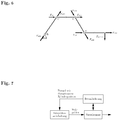
- the planned structure of the vibration damping is divided into the in Fig. 2 Subsystems shown: geometry control, pre-control, control (with observer) and feedforward control.
- the geometry control serves to generate trajectories for the distribution boom.
- the trajectories are a time function for position, speed, acceleration and / or jerk of the joint axes of the distributor boom. They are adapted in the feedforward control to the dynamics of the system and given the control as the setpoint.
- the regulation which in Fig. 4 is again divided into two parts: the axis control ( Fig. 5 ) and the control for damping the vibrations and position control with the controller and the observer.
- the method comprises an active vibration damping to reduce vibrations in the distribution boom. It is distinguished between the desired movements of the segments by the operator and the vibrations excited by the movement.
- the vibration damping takes into account the desired movement and dampens only the resulting structural vibrations. The vibrations due to concrete production are also reduced.
- the goal of vibration damping is to reduce vibrations throughout the distribution boom.
- the vibration state of the entire arm is estimated from the vibrations of the individual segments.
- the distributor boom has variable natural frequencies as a function of the position and inclination of the segments.
- the vibration damping takes into account this variability of the natural frequencies as a function of the mast position.
- the first natural frequencies are the biggest influence on the vibration behavior.
- the vibration state of the distributor boom is detected by rotation rate sensors 18 to 21.
- the sensors are mounted on one or more segments 4 to 7 and measure the rate of rotation about the hinge axes.
- the advantage of these sensors for vibration detection is that, in contrast to conventional sensors (eg strain gauges) can be easily mounted.
- the sensor can be mounted on all outer and inner sides of the segment.
- the MEMS-based rotation rate sensors are also cost-effective, robust and low-maintenance.
- the rotation rate sensor 18 to 21 is mounted in the front region of the respective segment 4 to 7 in order to optimally detect the structural vibrations. Due to the serial kinematics of the manipulator, the measured rate of rotation of a segment also includes the oscillation of the preceding segment. This circumstance will be taken into account in the draft regulation.
- the position of the distributor boom is determined by directly or indirectly measuring the relative joint angles between the segments. For example, as a measuring arrangement, a detection of the relative joint angle via rotary encoder.
- the control design is based on a mathematical model of the distribution boom.
- the mechanical system is represented by a dynamic model.
- the distributor boom is modeled by a rigid body model with actuated joints B to E. Additional virtual joints take into account the flexibility in the segments. For each segment, an additional virtual joint with spring and damper elements is introduced. The spring and damping constants are chosen so that the deflection and the first natural frequency of the real segment are maintained.
- the model of the distributor boom is composed of several segments. The rigidity of the overall structure results from the rigidity of the individual segments. Since the overall structure is composed of several segments, higher natural frequencies are also reproduced.
- This type of modeling represents a physically motivated discretization of the infinitely dimensional, elastic distribution mast.
- the advantage is that well-developed and efficient rigid body formalisms can be used for modeling.
- the resulting model also has a relatively low system order. Unlike a modal model reduction, the system state of the virtual joints continues to be a physical variable. It describes the concentrated deflection and vibration of the segment.
- the observer uses the inputs and outputs of the system to reconstruct the system state x.
- the inputs of the system u are the setpoints of the hydraulics.
- the outputs y are the measured values of the position and the vibration status of the distributor boom. Due to the fusion of the various measurement signals, the robustness of the vibration damping improves compared to the measuring principle-related drift phenomena of the rotation rate sensor.
- the model-based observer also ensures that the measurement signal of the rotation rate sensors is divided into the separate parts of the joint movement and the oscillation.
- the control selectively dampens the structural vibrations without the set movement to influence.
- the observer gain L is determined by a suitable method such. As Polvorgabe or selected by a Kalman filter.
- the poles are positioned in the complex half-plane so that the damping of the system increases.
- the vibrations in the distribution boom are thus damped.
- the controller receives the estimated state of the observer x , amplifies the signals and supplies them as setpoints of the hydraulics (see Fig. 4 ).
- the control gain K is determined by a suitable method such as. Polvorgabe or optimization-based method (LQR) is calculated.
- the observer and controller design process described above applies to a specific equilibrium position of the distributor boom. For a change in the mast position, therefore, the design process is repeated and adapted to the current position. By tracking the control parameters, the functionality of the vibration damping is ensured for each mast position.
- the vibration damping can also be used for vibrations in the horizontal plane.
- the hydraulic motor on the mast block acts as an actuator.
- the pole position around the vertical axis is detected by an angle encoder.
- the rotation angle sensors for vibration measurement are in this case by a detection direction executed in the horizontal plane and torsion or expanded.
- the sensors are mounted on one or more segments and measure the rate of rotation about the vertical axis and the longitudinal axis.
- the dynamic model of the distributor boom (Section 5.3.3) is supplemented by a horizontal component.
- the virtual joints in the segments are designed as multi-axis hinges that detect bending in the horizontal plane and torsion.
- the rotation around the vertical axis is taken into account by a hinge on the turntable.
- the type and structure of the model are retained against section 5.3.3.
- an observer and a feedback gain are designed for the linearized extended model.
- a separate horizontal vibration damping or a combined vertical and horizontal vibration damping can be implemented.
- the model-based observer ensures that the measuring signal of the rotation rate sensors is divided into the separate components of the vertical axis movement and the oscillation.
- the control selectively dampens the structural vibrations of horizontal bending and torsion without affecting the setpoint movement.
- the movement specifications of the operator are explicitly taken into account by the vibration damping. That is, the desired movement is allowed by the scheme and dampened only the superimposed structural vibrations.
- a pilot control is also provided. This calculates from the setpoint of the operator control signals, who perform the desired mast movement and thereby stimulate no vibration.
- a notch filter is used which, depending on the current mast position, suppresses the natural frequencies of the distributor mast during the movement (see Fig. 3 ).
- the setpoint signals for the hydraulics are converted by a subordinate axis control on the cylinders.
- the axis control converts a nominal angular velocity preset u of the joints into the translatory actual velocity of the cylinders.
- the deflection kinematics as well as nonlinearities of the hydraulics are taken into account by a pilot control (see Fig. 5 ).
- a measure of the feedback can be carried out either the pressure, the cylinder position or the cylinder speed.
- the cylinder speed can also be calculated from the position via a separate signal processing.
- the cylinders transmit the force F u to the distributor boom and thus generate a movement of the joints.
- the axis control is as described above decentralized and separately subordinate each joint.
- the advantage of disturbance variable over traditional oscillation damping is that the disturbances can be compensated before they affect the system. That is, the excitation of concrete production is eliminated before it is visible as vibration in the distribution boom.
- the objective of feedforward control is thus the reduction of vibrations in the distribution boom on the basis of characteristic measured variables of concrete extraction.
- the measured variables describe the state of concrete conveyance and not the vibration state of the distributor boom.
- Typical measures of concrete delivery are the pressure at the inlet of the delivery line, the frequency of the pumping process and the position and speed of the delivery piston.
- the disturbing forces on the placing boom are reconstructed via a model of concrete conveyance and switched to the actuators.
- the gain can be designed to eliminate the influence of disturbance forces on a specific point of the distribution boom.
- the mast tip is selected to keep the position of the end tube calm and constant.
- the modeling of concrete conveyance maps the concrete flow in the delivery line from the feed pump in the vehicle to the end hose at the top of the mast.
- the flow-related disturbance forces of concrete conveyance on the distribution mast are calculated.
- the boundary layer acts like a lubricating film and reduces the friction forces in the wall area.
- Other factors include the variable level factor in the delivery piston and the amount of dissolved air in the concrete.
- the uncertainty and variability of the above factors lead to a direct, purely substance-based modeling with large Difficulties connected. For this reason, modeling based on measurements is proposed. The basic idea is to dispense with the exact mapping of the flow conditions within the pipe and instead only to consider the forces acting on the pipe wall.
- the approach uses an equivalent Newtonian fluid to model the frictional and inertial forces of the fluid on the tube wall.
- the material properties of the equivalent fluid are determined from the measured quantities of concrete production.
- at least the viscosity of the equivalent fluid is determined from the concrete pressure and the flow rate of the concrete.
- the density of the equivalent fluid is a stored average for the density of concrete.
- the output variables of the model are the concentrated disturbance forces F d in each joint of the concrete pump (see Fig. 6 ).
- the effect of the concentrated disturbance forces F d is calculated via a coupling with a mechanical model of the distribution boom.
- the mechanical model takes into account the dynamic and elastic deformation of the segments under the influence of the disturbing forces over the entire distribution boom.
- the coupled model of concrete conveyance and distributor boom is used for the design of a model-based dynamic disturbance variable application.
- the model is extended by a control loop for reducing the disturbance variables in the distribution boom (see disturbance model control loop in Fig. 8 ).
- a control loop for reducing the disturbance variables in the distribution boom (see disturbance model control loop in Fig. 8 ).
- This has advantages for the control design, since no track uncertainties or disturbances occur.
- the entire state vector is available without the use of an observer.
- the control is designed so that the influence of the disturbing forces on the top of the mast is minimized.
- the feedforward control is combined with traditional vibration damping to compensate for oscillations from the movement of the mast and uncertainties in the modeling.
- the vibration damping is based on the measurement and the return of the position and the vibration state of the distribution boom.
- the control is designed in such a way that the manipulated variables of the feedforward control u d act unhindered on the line.
- the vibration damping only intervenes if the states of the real route deviate from the states of the virtual model.
- the hydraulic pressure of the delivery cylinder can be measured.
- the corresponding concrete pressure results from a conversion with the piston area ratio.
- the flow rate of the concrete from the speed of the delivery cylinder can be determined.
- the basic idea of the method is to estimate the disturbance forces from the measured values of the distributor boom.
- the periodicity of concrete production is used to establish a modal model of the disturbance forces.
- the model is composed of the fundamental frequency and its multiples.
- the individual states simulate the vibrational form of the disturbance variable as modal coordinates.
- a modal coordinate has no physical meaning, but only reflects the proportion of the respective frequency at the waveform of the disturbance.
- the disturbance forces are estimated by a disturbance observer or an asymptotic disturbance compensation from the measurements of the distribution boom.
- the estimation methods are based on the inner model principle.
- the principle defines that a stable control loop can completely suppress a disturbance only if it has an internal model of the disturbance signal.
- the model is border stable and consists only of conjugate complex pairs of poles of the frequencies on the imaginary axis of the complex half-plane together.
- the observer or the asymptotic noise compensation the initial state of the modal model is adapted from the measurement signals of the distribution boom. This corresponds to an estimate of the unknown amplitude and phase position of the disturbing forces.
- the greater number of frequencies takes more time to learn the present waveform.
- a transient movement occurs, whose Amplitude increases with the number of frequencies.
- the number of frequencies must be selected so that on the one hand the disturbance is mapped sufficiently accurate and on the other hand, the transient response occurs briefly and with low amplitude.
- the reconstructed disturbance variables are applied to the actuators of the distributor mast via a controller (see Fig. 9 ).
- the feedforward control is combined with a vibration damping based on the measured variables of the distributor boom y in order to ensure the stability of the system.
- the states of the system are estimated based on the model of the distribution boom and the disturbance model by the disturbance observer.
- the measured variables include the mast position and the vibration state of the distributor mast.
- the regulator in Fig. 9 thus amplifies the estimated disturbances and states of the system.
- the feedforward control can be designed so that the influence of disturbing forces on the mast tip is minimized.
- the observer or the asymptotic interference compensation learns the disturbance forces from the measured values y of the dynamic oscillation state of the distributor boom. This can reduce the number of sensors for conveying concrete.
- the required measured variable is the pump frequency, which can be determined via the switching times of the delivery cylinders in the software.
- a further advantage of the method is the robustness against changes in track parameters and variation of the concrete properties.
- the setpoint signals for the hydraulics are converted by a subordinate axis control on the cylinders.
- the axis control converts a desired angular velocity specification of the joints into the translatory actual velocity of the cylinders.
- the deflection kinematics as well as nonlinearities of the hydraulics are taken into account by a pilot control. Depending on the version, a return of the pressure or the cylinder position or speed can be implemented.
- the axis control is decentralized and therefore separately subordinate to each joint.
- the movement specifications of the operator are explicitly taken into account by the feedforward control and vibration damping. That is, the desired movement is allowed by the scheme and dampened only the superimposed structural vibrations.
- a pilot control is also provided. This calculates from the setpoint of the operator control signals ⁇ soll , which perform the desired mast movement and thereby stimulate no vibration.
- a notch filter is used which, depending on the current mast position, suppresses the natural frequencies of the distributor mast during the movement.
- the feedforward control is for the presented Störssennaufscigenen in the 8 and 9 characterized by a signal block.
- the pilot control signal ⁇ soll is taken into account additionally in the disturbance model control loop.
Landscapes
- Engineering & Computer Science (AREA)
- Mechanical Engineering (AREA)
- Architecture (AREA)
- Civil Engineering (AREA)
- Structural Engineering (AREA)
- On-Site Construction Work That Accompanies The Preparation And Application Of Concrete (AREA)
- Reciprocating Pumps (AREA)
Applications Claiming Priority (1)
| Application Number | Priority Date | Filing Date | Title |
|---|---|---|---|
| DE102018109057.9A DE102018109057A1 (de) | 2018-04-17 | 2018-04-17 | Betonpumpe |
Publications (2)
| Publication Number | Publication Date |
|---|---|
| EP3556969A1 true EP3556969A1 (fr) | 2019-10-23 |
| EP3556969B1 EP3556969B1 (fr) | 2023-11-08 |
Family
ID=66092246
Family Applications (1)
| Application Number | Title | Priority Date | Filing Date |
|---|---|---|---|
| EP19167399.5A Active EP3556969B1 (fr) | 2018-04-17 | 2019-04-04 | Pompe à béton |
Country Status (3)
| Country | Link |
|---|---|
| EP (1) | EP3556969B1 (fr) |
| DE (1) | DE102018109057A1 (fr) |
| ES (1) | ES2969925T3 (fr) |
Cited By (7)
| Publication number | Priority date | Publication date | Assignee | Title |
|---|---|---|---|---|
| CN112942839A (zh) * | 2021-04-20 | 2021-06-11 | 江苏理工学院 | 一种移动式混凝土自动浇筑机及其控制系统 |
| CN114562111A (zh) * | 2022-02-14 | 2022-05-31 | 三一汽车制造有限公司 | 臂架位置确定方法、装置、设备及作业机械 |
| CN114756063A (zh) * | 2022-03-30 | 2022-07-15 | 徐州徐工施维英机械有限公司 | 一种臂架轨迹规划的控制方法及泵车 |
| WO2022205639A1 (fr) * | 2021-03-31 | 2022-10-06 | 三一汽车制造有限公司 | Appareil de flèche et engin d'ingénierie |
| CN117005691A (zh) * | 2023-08-08 | 2023-11-07 | 河北吉达重工机械股份有限公司 | 一种混凝土布料机 |
| CN118407621A (zh) * | 2023-03-27 | 2024-07-30 | 湖南三一工业职业技术学院 | 一种基于气压系统的泵车臂架防振动控制装置 |
| CN120311962A (zh) * | 2025-03-14 | 2025-07-15 | 浙江大学 | 一种用于建筑3d打印带线驱动软管的电液混合机械臂 |
Families Citing this family (10)
| Publication number | Priority date | Publication date | Assignee | Title |
|---|---|---|---|---|
| DE102019105871A1 (de) | 2019-03-07 | 2020-09-10 | Liebherr-Mischtechnik Gmbh | Gelenkarm-Steuerung einer Betonpumpe |
| DE102019105817A1 (de) | 2019-03-07 | 2020-09-10 | Liebherr-Mischtechnik Gmbh | Gelenkarm-Steuerung einer Betonpumpe |
| DE102019105814A1 (de) | 2019-03-07 | 2020-09-10 | Liebherr-Mischtechnik Gmbh | Gelenkarm-Steuerung einer Betonpumpe |
| CN111441586A (zh) * | 2020-04-10 | 2020-07-24 | 中国建筑第八工程局有限公司 | 自适应智能混凝土布料系统及方法 |
| CN112049426B (zh) * | 2020-08-31 | 2022-02-25 | 三一汽车制造有限公司 | 臂架控制系统、方法和作业车辆 |
| DE102021107139A1 (de) * | 2021-03-23 | 2022-09-29 | Putzmeister Engineering Gmbh | Betriebsüberwachung für ein Dickstofffördersystem |
| DE102021107142A1 (de) | 2021-03-23 | 2022-09-29 | Putzmeister Engineering Gmbh | Standsicherheitsüberwachung für ein Dickstofffördersystem |
| DE102021134513A1 (de) | 2021-12-23 | 2023-06-29 | Putzmeister Engineering Gmbh | Dickstofffördersystem |
| CN114819158B (zh) * | 2022-03-24 | 2023-04-07 | 浙江大学 | 基于分布式负载口独立控制阀组的混凝土泵车臂架运动抑振方法 |
| CN116205004A (zh) * | 2023-03-14 | 2023-06-02 | 中联重科股份有限公司 | 臂架姿态的确定方法、臂架的控制方法及确定装置 |
Citations (3)
| Publication number | Priority date | Publication date | Assignee | Title |
|---|---|---|---|---|
| JP2000282687A (ja) * | 1999-03-31 | 2000-10-10 | Ishikawajima Constr Mach Co | ブーム付コンクリートポンプ車の運転制御装置 |
| EP1772588A2 (fr) * | 2005-09-08 | 2007-04-11 | Iveco Magirus Ag | Echelle articulée ou plate-forme mobile avec dispositif de contrôle du mouvement et dispositif d'amortissement actif de vibrations |
| CN105317217A (zh) * | 2014-06-17 | 2016-02-10 | 中联重科股份有限公司 | 臂架回转振动抑制设备、系统、方法及工程机械 |
Family Cites Families (8)
| Publication number | Priority date | Publication date | Assignee | Title |
|---|---|---|---|---|
| DE10004779A1 (de) | 2000-02-03 | 2001-08-09 | Putzmeister Ag | Dickstoffförderer mit Verteilermast sowie Verfahren zum pulsierenden Pumpen von Dickstoffen |
| DE10101570B4 (de) | 2001-01-15 | 2008-12-04 | Schwing Gmbh | Großmanipulator mit Schwingungsdämpfung |
| DE10240180A1 (de) | 2002-08-27 | 2004-03-11 | Putzmeister Ag | Vorrichtung zur Betätigung eines Knickmasts |
| ITUD20080057A1 (it) | 2008-03-17 | 2009-09-18 | Cifa Spa | Procedimento di controllo delle vibrazioni di un braccio articolato per il pompaggio di calcestruzzo, e relativo dispositivo |
| US9651112B2 (en) | 2011-10-20 | 2017-05-16 | Zoomlion Heavy Industry Science And Technology Co., Ltd. | Vibration suppression method, controller, device of boom and pump truck |
| AT514116A1 (de) | 2013-04-09 | 2014-10-15 | Ttcontrol Gmbh | Regelsystem und Verfahren zum Steuern der Orientierung eines Segments eines Manipulators |
| CN105637232B (zh) * | 2013-08-30 | 2018-06-19 | 伊顿公司 | 使用一对独立液压计量阀降低动臂振荡的控制方法和系统 |
| DE102015102368A1 (de) | 2015-02-19 | 2016-08-25 | Schwing Gmbh | Positionsregelung Mastspitze |
-
2018
- 2018-04-17 DE DE102018109057.9A patent/DE102018109057A1/de not_active Withdrawn
-
2019
- 2019-04-04 EP EP19167399.5A patent/EP3556969B1/fr active Active
- 2019-04-04 ES ES19167399T patent/ES2969925T3/es active Active
Patent Citations (3)
| Publication number | Priority date | Publication date | Assignee | Title |
|---|---|---|---|---|
| JP2000282687A (ja) * | 1999-03-31 | 2000-10-10 | Ishikawajima Constr Mach Co | ブーム付コンクリートポンプ車の運転制御装置 |
| EP1772588A2 (fr) * | 2005-09-08 | 2007-04-11 | Iveco Magirus Ag | Echelle articulée ou plate-forme mobile avec dispositif de contrôle du mouvement et dispositif d'amortissement actif de vibrations |
| CN105317217A (zh) * | 2014-06-17 | 2016-02-10 | 中联重科股份有限公司 | 臂架回转振动抑制设备、系统、方法及工程机械 |
Non-Patent Citations (1)
| Title |
|---|
| SOPHIE ZORN: "Modellbasierte aktive Schwingungstilgung eines Multilink-Groÿraummanipulators", 8 December 2017 (2017-12-08), XP055616776, Retrieved from the Internet <URL:https://d-nb.info/1156851432/34> [retrieved on 20190829] * |
Cited By (10)
| Publication number | Priority date | Publication date | Assignee | Title |
|---|---|---|---|---|
| WO2022205639A1 (fr) * | 2021-03-31 | 2022-10-06 | 三一汽车制造有限公司 | Appareil de flèche et engin d'ingénierie |
| CN112942839A (zh) * | 2021-04-20 | 2021-06-11 | 江苏理工学院 | 一种移动式混凝土自动浇筑机及其控制系统 |
| CN112942839B (zh) * | 2021-04-20 | 2022-04-01 | 江苏理工学院 | 一种移动式混凝土自动浇筑机的控制方法 |
| CN114562111A (zh) * | 2022-02-14 | 2022-05-31 | 三一汽车制造有限公司 | 臂架位置确定方法、装置、设备及作业机械 |
| CN114562111B (zh) * | 2022-02-14 | 2023-09-08 | 三一汽车制造有限公司 | 臂架位置确定方法、装置、设备及作业机械 |
| CN114756063A (zh) * | 2022-03-30 | 2022-07-15 | 徐州徐工施维英机械有限公司 | 一种臂架轨迹规划的控制方法及泵车 |
| CN118407621A (zh) * | 2023-03-27 | 2024-07-30 | 湖南三一工业职业技术学院 | 一种基于气压系统的泵车臂架防振动控制装置 |
| CN117005691A (zh) * | 2023-08-08 | 2023-11-07 | 河北吉达重工机械股份有限公司 | 一种混凝土布料机 |
| CN117005691B (zh) * | 2023-08-08 | 2024-01-30 | 河北吉达重工机械股份有限公司 | 一种混凝土布料机 |
| CN120311962A (zh) * | 2025-03-14 | 2025-07-15 | 浙江大学 | 一种用于建筑3d打印带线驱动软管的电液混合机械臂 |
Also Published As
| Publication number | Publication date |
|---|---|
| ES2969925T3 (es) | 2024-05-23 |
| DE102018109057A1 (de) | 2019-10-17 |
| EP3556969B1 (fr) | 2023-11-08 |
Similar Documents
| Publication | Publication Date | Title |
|---|---|---|
| EP3556969B1 (fr) | Pompe à béton | |
| EP3556967B1 (fr) | Manipulateur de grande taille, en particulier pour pompes à béton | |
| EP3556968A1 (fr) | Pompe à béton | |
| EP3784616B1 (fr) | Grue et procédé pour commander une grue de ce type | |
| EP3649072B1 (fr) | Grue et procédé de commande d'une telle grue | |
| EP1326798B1 (fr) | Grue ou excavateur pour retourner une charge suspendue a un cable porteur avec amortissement du mouvement pendulaire de la charge | |
| DE10240180A1 (de) | Vorrichtung zur Betätigung eines Knickmasts | |
| EP3705663B1 (fr) | Commande à bras articulaire d'une pompe à béton | |
| EP1882795B1 (fr) | Grand manipulateur pourvu d'un amortisseur de vibrations | |
| EP3705662B1 (fr) | Commande à bras articulaire d'une pompe à béton | |
| EP3705664B1 (fr) | Commande à bras articulaire d'une pompe à béton | |
| EP3259221A1 (fr) | Régulation de position d'une pointe de mât | |
| WO2004106215A1 (fr) | Grue ou excavatrice destinee a la manipulation d'une charge suspendue a un cable presentant un systeme de guidage optimise | |
| EP3689141A1 (fr) | Dispositif d'extraction de liquides et/ou d'agents actifs solides et procédé de commande d'un tel dispositif | |
| DE102015208577A1 (de) | Verfahren zur Ansteuerung eines Knickmasts in einem Großmanipulator | |
| DE102012220035A1 (de) | Bewegungssystem, das ausgestaltet ist, um eine nutzlast zu bewegen | |
| DE102005042721A1 (de) | Gelenkleiter oder Hubbühne mit Bahnsteuerung und aktiver Schwingungsdämpfung | |
| WO2022236346A1 (fr) | Procédé de commande en boucle ouverte et/ou en boucle fermée d'un engin de levage monté sur un véhicule | |
| DE102015100669A1 (de) | Anti-pendel-steuerverfahren mit einstellbarer unterstützung für den transport einer schwebenden last | |
| DE60123506T2 (de) | Drehleiter-Regelung | |
| DE10029579A1 (de) | Verfahren zur Orientierung der Last in Krananlagen | |
| DE102016004466A1 (de) | Verfahren zum Bewegen des letzten Gliedes einer kinematischen Kette sowie Vorrichtung und Arbeitsmaschine zum Durchführen des Verfahrens | |
| EP4413220B1 (fr) | Système de distribution d'agent d'étanchéité | |
| DE102023213198A1 (de) | Verfahren zur Bestimmung eines Gewichts einer durch einen Ausleger einer Arbeitsmaschine aufgenommenen Last |
Legal Events
| Date | Code | Title | Description |
|---|---|---|---|
| PUAI | Public reference made under article 153(3) epc to a published international application that has entered the european phase |
Free format text: ORIGINAL CODE: 0009012 |
|
| STAA | Information on the status of an ep patent application or granted ep patent |
Free format text: STATUS: THE APPLICATION HAS BEEN PUBLISHED |
|
| AK | Designated contracting states |
Kind code of ref document: A1 Designated state(s): AL AT BE BG CH CY CZ DE DK EE ES FI FR GB GR HR HU IE IS IT LI LT LU LV MC MK MT NL NO PL PT RO RS SE SI SK SM TR |
|
| AX | Request for extension of the european patent |
Extension state: BA ME |
|
| STAA | Information on the status of an ep patent application or granted ep patent |
Free format text: STATUS: REQUEST FOR EXAMINATION WAS MADE |
|
| 17P | Request for examination filed |
Effective date: 20200421 |
|
| STAA | Information on the status of an ep patent application or granted ep patent |
Free format text: STATUS: EXAMINATION IS IN PROGRESS |
|
| 17Q | First examination report despatched |
Effective date: 20220527 |
|
| GRAP | Despatch of communication of intention to grant a patent |
Free format text: ORIGINAL CODE: EPIDOSNIGR1 |
|
| STAA | Information on the status of an ep patent application or granted ep patent |
Free format text: STATUS: GRANT OF PATENT IS INTENDED |
|
| RIC1 | Information provided on ipc code assigned before grant |
Ipc: B66C 23/68 20060101ALI20230616BHEP Ipc: B25J 9/00 20060101ALI20230616BHEP Ipc: B66C 13/06 20060101ALI20230616BHEP Ipc: E04G 21/04 20060101AFI20230616BHEP |
|
| INTG | Intention to grant announced |
Effective date: 20230703 |
|
| GRAS | Grant fee paid |
Free format text: ORIGINAL CODE: EPIDOSNIGR3 |
|
| GRAA | (expected) grant |
Free format text: ORIGINAL CODE: 0009210 |
|
| STAA | Information on the status of an ep patent application or granted ep patent |
Free format text: STATUS: THE PATENT HAS BEEN GRANTED |
|
| AK | Designated contracting states |
Kind code of ref document: B1 Designated state(s): AL AT BE BG CH CY CZ DE DK EE ES FI FR GB GR HR HU IE IS IT LI LT LU LV MC MK MT NL NO PL PT RO RS SE SI SK SM TR |
|
| REG | Reference to a national code |
Ref country code: GB Ref legal event code: FG4D Free format text: NOT ENGLISH |
|
| REG | Reference to a national code |
Ref country code: CH Ref legal event code: EP |
|
| REG | Reference to a national code |
Ref country code: DE Ref legal event code: R096 Ref document number: 502019009851 Country of ref document: DE |
|
| REG | Reference to a national code |
Ref country code: IE Ref legal event code: FG4D Free format text: LANGUAGE OF EP DOCUMENT: GERMAN |
|
| REG | Reference to a national code |
Ref country code: LT Ref legal event code: MG9D |
|
| REG | Reference to a national code |
Ref country code: NL Ref legal event code: MP Effective date: 20231108 |
|
| PG25 | Lapsed in a contracting state [announced via postgrant information from national office to epo] |
Ref country code: GR Free format text: LAPSE BECAUSE OF FAILURE TO SUBMIT A TRANSLATION OF THE DESCRIPTION OR TO PAY THE FEE WITHIN THE PRESCRIBED TIME-LIMIT Effective date: 20240209 |
|
| PG25 | Lapsed in a contracting state [announced via postgrant information from national office to epo] |
Ref country code: IS Free format text: LAPSE BECAUSE OF FAILURE TO SUBMIT A TRANSLATION OF THE DESCRIPTION OR TO PAY THE FEE WITHIN THE PRESCRIBED TIME-LIMIT Effective date: 20240308 |
|
| PG25 | Lapsed in a contracting state [announced via postgrant information from national office to epo] |
Ref country code: LT Free format text: LAPSE BECAUSE OF FAILURE TO SUBMIT A TRANSLATION OF THE DESCRIPTION OR TO PAY THE FEE WITHIN THE PRESCRIBED TIME-LIMIT Effective date: 20231108 |
|
| PG25 | Lapsed in a contracting state [announced via postgrant information from national office to epo] |
Ref country code: NL Free format text: LAPSE BECAUSE OF FAILURE TO SUBMIT A TRANSLATION OF THE DESCRIPTION OR TO PAY THE FEE WITHIN THE PRESCRIBED TIME-LIMIT Effective date: 20231108 |
|
| PG25 | Lapsed in a contracting state [announced via postgrant information from national office to epo] |
Ref country code: NL Free format text: LAPSE BECAUSE OF FAILURE TO SUBMIT A TRANSLATION OF THE DESCRIPTION OR TO PAY THE FEE WITHIN THE PRESCRIBED TIME-LIMIT Effective date: 20231108 Ref country code: LT Free format text: LAPSE BECAUSE OF FAILURE TO SUBMIT A TRANSLATION OF THE DESCRIPTION OR TO PAY THE FEE WITHIN THE PRESCRIBED TIME-LIMIT Effective date: 20231108 Ref country code: IS Free format text: LAPSE BECAUSE OF FAILURE TO SUBMIT A TRANSLATION OF THE DESCRIPTION OR TO PAY THE FEE WITHIN THE PRESCRIBED TIME-LIMIT Effective date: 20240308 Ref country code: GR Free format text: LAPSE BECAUSE OF FAILURE TO SUBMIT A TRANSLATION OF THE DESCRIPTION OR TO PAY THE FEE WITHIN THE PRESCRIBED TIME-LIMIT Effective date: 20240209 Ref country code: BG Free format text: LAPSE BECAUSE OF FAILURE TO SUBMIT A TRANSLATION OF THE DESCRIPTION OR TO PAY THE FEE WITHIN THE PRESCRIBED TIME-LIMIT Effective date: 20240208 Ref country code: PT Free format text: LAPSE BECAUSE OF FAILURE TO SUBMIT A TRANSLATION OF THE DESCRIPTION OR TO PAY THE FEE WITHIN THE PRESCRIBED TIME-LIMIT Effective date: 20240308 |
|
| REG | Reference to a national code |
Ref country code: ES Ref legal event code: FG2A Ref document number: 2969925 Country of ref document: ES Kind code of ref document: T3 Effective date: 20240523 |
|
| PG25 | Lapsed in a contracting state [announced via postgrant information from national office to epo] |
Ref country code: SE Free format text: LAPSE BECAUSE OF FAILURE TO SUBMIT A TRANSLATION OF THE DESCRIPTION OR TO PAY THE FEE WITHIN THE PRESCRIBED TIME-LIMIT Effective date: 20231108 Ref country code: RS Free format text: LAPSE BECAUSE OF FAILURE TO SUBMIT A TRANSLATION OF THE DESCRIPTION OR TO PAY THE FEE WITHIN THE PRESCRIBED TIME-LIMIT Effective date: 20231108 Ref country code: PL Free format text: LAPSE BECAUSE OF FAILURE TO SUBMIT A TRANSLATION OF THE DESCRIPTION OR TO PAY THE FEE WITHIN THE PRESCRIBED TIME-LIMIT Effective date: 20231108 Ref country code: NO Free format text: LAPSE BECAUSE OF FAILURE TO SUBMIT A TRANSLATION OF THE DESCRIPTION OR TO PAY THE FEE WITHIN THE PRESCRIBED TIME-LIMIT Effective date: 20240208 Ref country code: LV Free format text: LAPSE BECAUSE OF FAILURE TO SUBMIT A TRANSLATION OF THE DESCRIPTION OR TO PAY THE FEE WITHIN THE PRESCRIBED TIME-LIMIT Effective date: 20231108 Ref country code: HR Free format text: LAPSE BECAUSE OF FAILURE TO SUBMIT A TRANSLATION OF THE DESCRIPTION OR TO PAY THE FEE WITHIN THE PRESCRIBED TIME-LIMIT Effective date: 20231108 |
|
| PG25 | Lapsed in a contracting state [announced via postgrant information from national office to epo] |
Ref country code: DK Free format text: LAPSE BECAUSE OF FAILURE TO SUBMIT A TRANSLATION OF THE DESCRIPTION OR TO PAY THE FEE WITHIN THE PRESCRIBED TIME-LIMIT Effective date: 20231108 |
|
| PGFP | Annual fee paid to national office [announced via postgrant information from national office to epo] |
Ref country code: ES Payment date: 20240503 Year of fee payment: 6 |
|
| PG25 | Lapsed in a contracting state [announced via postgrant information from national office to epo] |
Ref country code: CZ Free format text: LAPSE BECAUSE OF FAILURE TO SUBMIT A TRANSLATION OF THE DESCRIPTION OR TO PAY THE FEE WITHIN THE PRESCRIBED TIME-LIMIT Effective date: 20231108 |
|
| PG25 | Lapsed in a contracting state [announced via postgrant information from national office to epo] |
Ref country code: SK Free format text: LAPSE BECAUSE OF FAILURE TO SUBMIT A TRANSLATION OF THE DESCRIPTION OR TO PAY THE FEE WITHIN THE PRESCRIBED TIME-LIMIT Effective date: 20231108 |
|
| PG25 | Lapsed in a contracting state [announced via postgrant information from national office to epo] |
Ref country code: SM Free format text: LAPSE BECAUSE OF FAILURE TO SUBMIT A TRANSLATION OF THE DESCRIPTION OR TO PAY THE FEE WITHIN THE PRESCRIBED TIME-LIMIT Effective date: 20231108 Ref country code: SK Free format text: LAPSE BECAUSE OF FAILURE TO SUBMIT A TRANSLATION OF THE DESCRIPTION OR TO PAY THE FEE WITHIN THE PRESCRIBED TIME-LIMIT Effective date: 20231108 Ref country code: RO Free format text: LAPSE BECAUSE OF FAILURE TO SUBMIT A TRANSLATION OF THE DESCRIPTION OR TO PAY THE FEE WITHIN THE PRESCRIBED TIME-LIMIT Effective date: 20231108 Ref country code: EE Free format text: LAPSE BECAUSE OF FAILURE TO SUBMIT A TRANSLATION OF THE DESCRIPTION OR TO PAY THE FEE WITHIN THE PRESCRIBED TIME-LIMIT Effective date: 20231108 Ref country code: DK Free format text: LAPSE BECAUSE OF FAILURE TO SUBMIT A TRANSLATION OF THE DESCRIPTION OR TO PAY THE FEE WITHIN THE PRESCRIBED TIME-LIMIT Effective date: 20231108 Ref country code: CZ Free format text: LAPSE BECAUSE OF FAILURE TO SUBMIT A TRANSLATION OF THE DESCRIPTION OR TO PAY THE FEE WITHIN THE PRESCRIBED TIME-LIMIT Effective date: 20231108 |
|
| REG | Reference to a national code |
Ref country code: DE Ref legal event code: R097 Ref document number: 502019009851 Country of ref document: DE |
|
| PGFP | Annual fee paid to national office [announced via postgrant information from national office to epo] |
Ref country code: TR Payment date: 20240402 Year of fee payment: 6 |
|
| PLBE | No opposition filed within time limit |
Free format text: ORIGINAL CODE: 0009261 |
|
| STAA | Information on the status of an ep patent application or granted ep patent |
Free format text: STATUS: NO OPPOSITION FILED WITHIN TIME LIMIT |
|
| 26N | No opposition filed |
Effective date: 20240809 |
|
| PG25 | Lapsed in a contracting state [announced via postgrant information from national office to epo] |
Ref country code: SI Free format text: LAPSE BECAUSE OF FAILURE TO SUBMIT A TRANSLATION OF THE DESCRIPTION OR TO PAY THE FEE WITHIN THE PRESCRIBED TIME-LIMIT Effective date: 20231108 |
|
| PG25 | Lapsed in a contracting state [announced via postgrant information from national office to epo] |
Ref country code: SI Free format text: LAPSE BECAUSE OF FAILURE TO SUBMIT A TRANSLATION OF THE DESCRIPTION OR TO PAY THE FEE WITHIN THE PRESCRIBED TIME-LIMIT Effective date: 20231108 |
|
| PG25 | Lapsed in a contracting state [announced via postgrant information from national office to epo] |
Ref country code: MC Free format text: LAPSE BECAUSE OF FAILURE TO SUBMIT A TRANSLATION OF THE DESCRIPTION OR TO PAY THE FEE WITHIN THE PRESCRIBED TIME-LIMIT Effective date: 20231108 |
|
| PG25 | Lapsed in a contracting state [announced via postgrant information from national office to epo] |
Ref country code: MC Free format text: LAPSE BECAUSE OF FAILURE TO SUBMIT A TRANSLATION OF THE DESCRIPTION OR TO PAY THE FEE WITHIN THE PRESCRIBED TIME-LIMIT Effective date: 20231108 |
|
| PG25 | Lapsed in a contracting state [announced via postgrant information from national office to epo] |
Ref country code: LU Free format text: LAPSE BECAUSE OF NON-PAYMENT OF DUE FEES Effective date: 20240404 |
|
| GBPC | Gb: european patent ceased through non-payment of renewal fee |
Effective date: 20240404 |
|
| REG | Reference to a national code |
Ref country code: BE Ref legal event code: MM Effective date: 20240430 |
|
| PG25 | Lapsed in a contracting state [announced via postgrant information from national office to epo] |
Ref country code: LU Free format text: LAPSE BECAUSE OF NON-PAYMENT OF DUE FEES Effective date: 20240404 |
|
| PG25 | Lapsed in a contracting state [announced via postgrant information from national office to epo] |
Ref country code: BE Free format text: LAPSE BECAUSE OF NON-PAYMENT OF DUE FEES Effective date: 20240430 |
|
| PG25 | Lapsed in a contracting state [announced via postgrant information from national office to epo] |
Ref country code: GB Free format text: LAPSE BECAUSE OF NON-PAYMENT OF DUE FEES Effective date: 20240404 |
|
| PG25 | Lapsed in a contracting state [announced via postgrant information from national office to epo] |
Ref country code: GB Free format text: LAPSE BECAUSE OF NON-PAYMENT OF DUE FEES Effective date: 20240404 Ref country code: BE Free format text: LAPSE BECAUSE OF NON-PAYMENT OF DUE FEES Effective date: 20240430 |
|
| PG25 | Lapsed in a contracting state [announced via postgrant information from national office to epo] |
Ref country code: IE Free format text: LAPSE BECAUSE OF NON-PAYMENT OF DUE FEES Effective date: 20240404 |
|
| PG25 | Lapsed in a contracting state [announced via postgrant information from national office to epo] |
Ref country code: IT Free format text: LAPSE BECAUSE OF NON-PAYMENT OF DUE FEES Effective date: 20240404 |
|
| PGFP | Annual fee paid to national office [announced via postgrant information from national office to epo] |
Ref country code: DE Payment date: 20250430 Year of fee payment: 7 |
|
| PGFP | Annual fee paid to national office [announced via postgrant information from national office to epo] |
Ref country code: FR Payment date: 20250426 Year of fee payment: 7 |
|
| PGFP | Annual fee paid to national office [announced via postgrant information from national office to epo] |
Ref country code: CH Payment date: 20250501 Year of fee payment: 7 |
|
| PGFP | Annual fee paid to national office [announced via postgrant information from national office to epo] |
Ref country code: AT Payment date: 20250424 Year of fee payment: 7 |
|
| PG25 | Lapsed in a contracting state [announced via postgrant information from national office to epo] |
Ref country code: CY Free format text: LAPSE BECAUSE OF FAILURE TO SUBMIT A TRANSLATION OF THE DESCRIPTION OR TO PAY THE FEE WITHIN THE PRESCRIBED TIME-LIMIT; INVALID AB INITIO Effective date: 20190404 |
|
| PG25 | Lapsed in a contracting state [announced via postgrant information from national office to epo] |
Ref country code: HU Free format text: LAPSE BECAUSE OF FAILURE TO SUBMIT A TRANSLATION OF THE DESCRIPTION OR TO PAY THE FEE WITHIN THE PRESCRIBED TIME-LIMIT; INVALID AB INITIO Effective date: 20190404 |
|
| PG25 | Lapsed in a contracting state [announced via postgrant information from national office to epo] |
Ref country code: FI Free format text: LAPSE BECAUSE OF FAILURE TO SUBMIT A TRANSLATION OF THE DESCRIPTION OR TO PAY THE FEE WITHIN THE PRESCRIBED TIME-LIMIT Effective date: 20231108 |
|
| PG25 | Lapsed in a contracting state [announced via postgrant information from national office to epo] |
Ref country code: IT Free format text: LAPSE BECAUSE OF NON-PAYMENT OF DUE FEES Effective date: 20240404 |
|
| PGFP | Annual fee paid to national office [announced via postgrant information from national office to epo] |
Ref country code: IT Payment date: 20250428 Year of fee payment: 7 |
|
| PGRI | Patent reinstated in contracting state [announced from national office to epo] |
Ref country code: IT Effective date: 20240902 |