EP3557056B1 - Circuit frigorifique à plusieurs étages de compresseur - Google Patents
Circuit frigorifique à plusieurs étages de compresseur Download PDFInfo
- Publication number
- EP3557056B1 EP3557056B1 EP19176434.9A EP19176434A EP3557056B1 EP 3557056 B1 EP3557056 B1 EP 3557056B1 EP 19176434 A EP19176434 A EP 19176434A EP 3557056 B1 EP3557056 B1 EP 3557056B1
- Authority
- EP
- European Patent Office
- Prior art keywords
- lubricant
- refrigerant circuit
- suction
- accordance
- crankcase
- Prior art date
- Legal status (The legal status is an assumption and is not a legal conclusion. Google has not performed a legal analysis and makes no representation as to the accuracy of the status listed.)
- Active
Links
Images



Classifications
-
- F—MECHANICAL ENGINEERING; LIGHTING; HEATING; WEAPONS; BLASTING
- F04—POSITIVE - DISPLACEMENT MACHINES FOR LIQUIDS; PUMPS FOR LIQUIDS OR ELASTIC FLUIDS
- F04B—POSITIVE-DISPLACEMENT MACHINES FOR LIQUIDS; PUMPS
- F04B39/00—Component parts, details, or accessories, of pumps or pumping systems specially adapted for elastic fluids, not otherwise provided for in, or of interest apart from, groups F04B25/00 - F04B37/00
- F04B39/02—Lubrication
- F04B39/0223—Lubrication characterised by the compressor type
- F04B39/023—Hermetic compressors
- F04B39/0238—Hermetic compressors with oil distribution channels
-
- F—MECHANICAL ENGINEERING; LIGHTING; HEATING; WEAPONS; BLASTING
- F04—POSITIVE - DISPLACEMENT MACHINES FOR LIQUIDS; PUMPS FOR LIQUIDS OR ELASTIC FLUIDS
- F04B—POSITIVE-DISPLACEMENT MACHINES FOR LIQUIDS; PUMPS
- F04B27/00—Multi-cylinder pumps specially adapted for elastic fluids and characterised by number or arrangement of cylinders
- F04B27/08—Multi-cylinder pumps specially adapted for elastic fluids and characterised by number or arrangement of cylinders having cylinders coaxial with, or parallel or inclined to, main shaft axis
- F04B27/10—Multi-cylinder pumps specially adapted for elastic fluids and characterised by number or arrangement of cylinders having cylinders coaxial with, or parallel or inclined to, main shaft axis having stationary cylinders
- F04B27/1036—Component parts, details, e.g. sealings, lubrication
- F04B27/109—Lubrication
-
- F—MECHANICAL ENGINEERING; LIGHTING; HEATING; WEAPONS; BLASTING
- F04—POSITIVE - DISPLACEMENT MACHINES FOR LIQUIDS; PUMPS FOR LIQUIDS OR ELASTIC FLUIDS
- F04B—POSITIVE-DISPLACEMENT MACHINES FOR LIQUIDS; PUMPS
- F04B39/00—Component parts, details, or accessories, of pumps or pumping systems specially adapted for elastic fluids, not otherwise provided for in, or of interest apart from, groups F04B25/00 - F04B37/00
- F04B39/02—Lubrication
-
- F—MECHANICAL ENGINEERING; LIGHTING; HEATING; WEAPONS; BLASTING
- F04—POSITIVE - DISPLACEMENT MACHINES FOR LIQUIDS; PUMPS FOR LIQUIDS OR ELASTIC FLUIDS
- F04B—POSITIVE-DISPLACEMENT MACHINES FOR LIQUIDS; PUMPS
- F04B39/00—Component parts, details, or accessories, of pumps or pumping systems specially adapted for elastic fluids, not otherwise provided for in, or of interest apart from, groups F04B25/00 - F04B37/00
- F04B39/02—Lubrication
- F04B39/0207—Lubrication with lubrication control systems
-
- F—MECHANICAL ENGINEERING; LIGHTING; HEATING; WEAPONS; BLASTING
- F04—POSITIVE - DISPLACEMENT MACHINES FOR LIQUIDS; PUMPS FOR LIQUIDS OR ELASTIC FLUIDS
- F04B—POSITIVE-DISPLACEMENT MACHINES FOR LIQUIDS; PUMPS
- F04B39/00—Component parts, details, or accessories, of pumps or pumping systems specially adapted for elastic fluids, not otherwise provided for in, or of interest apart from, groups F04B25/00 - F04B37/00
- F04B39/02—Lubrication
- F04B39/0223—Lubrication characterised by the compressor type
- F04B39/0276—Lubrication characterised by the compressor type the pump being of the reciprocating piston type, e.g. oscillating, free-piston compressors
-
- F—MECHANICAL ENGINEERING; LIGHTING; HEATING; WEAPONS; BLASTING
- F04—POSITIVE - DISPLACEMENT MACHINES FOR LIQUIDS; PUMPS FOR LIQUIDS OR ELASTIC FLUIDS
- F04B—POSITIVE-DISPLACEMENT MACHINES FOR LIQUIDS; PUMPS
- F04B39/00—Component parts, details, or accessories, of pumps or pumping systems specially adapted for elastic fluids, not otherwise provided for in, or of interest apart from, groups F04B25/00 - F04B37/00
- F04B39/02—Lubrication
- F04B39/0284—Constructional details, e.g. reservoirs in the casing
-
- F—MECHANICAL ENGINEERING; LIGHTING; HEATING; WEAPONS; BLASTING
- F04—POSITIVE - DISPLACEMENT MACHINES FOR LIQUIDS; PUMPS FOR LIQUIDS OR ELASTIC FLUIDS
- F04B—POSITIVE-DISPLACEMENT MACHINES FOR LIQUIDS; PUMPS
- F04B39/00—Component parts, details, or accessories, of pumps or pumping systems specially adapted for elastic fluids, not otherwise provided for in, or of interest apart from, groups F04B25/00 - F04B37/00
- F04B39/02—Lubrication
- F04B39/0284—Constructional details, e.g. reservoirs in the casing
- F04B39/0292—Lubrication of pistons or cylinders
-
- F—MECHANICAL ENGINEERING; LIGHTING; HEATING; WEAPONS; BLASTING
- F04—POSITIVE - DISPLACEMENT MACHINES FOR LIQUIDS; PUMPS FOR LIQUIDS OR ELASTIC FLUIDS
- F04B—POSITIVE-DISPLACEMENT MACHINES FOR LIQUIDS; PUMPS
- F04B39/00—Component parts, details, or accessories, of pumps or pumping systems specially adapted for elastic fluids, not otherwise provided for in, or of interest apart from, groups F04B25/00 - F04B37/00
- F04B39/12—Casings; Cylinders; Cylinder heads; Fluid connections
- F04B39/123—Fluid connections
-
- F—MECHANICAL ENGINEERING; LIGHTING; HEATING; WEAPONS; BLASTING
- F04—POSITIVE - DISPLACEMENT MACHINES FOR LIQUIDS; PUMPS FOR LIQUIDS OR ELASTIC FLUIDS
- F04B—POSITIVE-DISPLACEMENT MACHINES FOR LIQUIDS; PUMPS
- F04B39/00—Component parts, details, or accessories, of pumps or pumping systems specially adapted for elastic fluids, not otherwise provided for in, or of interest apart from, groups F04B25/00 - F04B37/00
- F04B39/12—Casings; Cylinders; Cylinder heads; Fluid connections
- F04B39/125—Cylinder heads
-
- F—MECHANICAL ENGINEERING; LIGHTING; HEATING; WEAPONS; BLASTING
- F04—POSITIVE - DISPLACEMENT MACHINES FOR LIQUIDS; PUMPS FOR LIQUIDS OR ELASTIC FLUIDS
- F04B—POSITIVE-DISPLACEMENT MACHINES FOR LIQUIDS; PUMPS
- F04B39/00—Component parts, details, or accessories, of pumps or pumping systems specially adapted for elastic fluids, not otherwise provided for in, or of interest apart from, groups F04B25/00 - F04B37/00
- F04B39/12—Casings; Cylinders; Cylinder heads; Fluid connections
- F04B39/128—Crankcases
-
- F—MECHANICAL ENGINEERING; LIGHTING; HEATING; WEAPONS; BLASTING
- F04—POSITIVE - DISPLACEMENT MACHINES FOR LIQUIDS; PUMPS FOR LIQUIDS OR ELASTIC FLUIDS
- F04B—POSITIVE-DISPLACEMENT MACHINES FOR LIQUIDS; PUMPS
- F04B53/00—Component parts, details or accessories not provided for in, or of interest apart from, groups F04B1/00 - F04B23/00 or F04B39/00 - F04B47/00
- F04B53/007—Cylinder heads
-
- F—MECHANICAL ENGINEERING; LIGHTING; HEATING; WEAPONS; BLASTING
- F04—POSITIVE - DISPLACEMENT MACHINES FOR LIQUIDS; PUMPS FOR LIQUIDS OR ELASTIC FLUIDS
- F04B—POSITIVE-DISPLACEMENT MACHINES FOR LIQUIDS; PUMPS
- F04B53/00—Component parts, details or accessories not provided for in, or of interest apart from, groups F04B1/00 - F04B23/00 or F04B39/00 - F04B47/00
- F04B53/18—Lubricating
-
- F—MECHANICAL ENGINEERING; LIGHTING; HEATING; WEAPONS; BLASTING
- F25—REFRIGERATION OR COOLING; COMBINED HEATING AND REFRIGERATION SYSTEMS; HEAT PUMP SYSTEMS; MANUFACTURE OR STORAGE OF ICE; LIQUEFACTION SOLIDIFICATION OF GASES
- F25B—REFRIGERATION MACHINES, PLANTS OR SYSTEMS; COMBINED HEATING AND REFRIGERATION SYSTEMS; HEAT PUMP SYSTEMS
- F25B2341/00—Details of ejectors not being used as compression device; Details of flow restrictors or expansion valves
- F25B2341/001—Ejectors not being used as compression device
- F25B2341/0016—Ejectors for creating an oil recirculation
Definitions
- the invention relates to a refrigerant circuit with a reciprocating piston compressor, comprising a crankcase in which a collecting space for lubricant is arranged, a cylinder housing in which at least one reciprocating piston can be moved in an oscillating manner, a valve plate closing the cylinder housing in which at least one inlet valve and one outlet valve are arranged, and a cylinder head in which a suction gas guide running towards the inlet valve and a pressure gas guide leading away from the outlet valve are provided.
- the US 4,413,954 discloses a swash plate compressor in whose cylinder block double-acting pistons are provided which are movable in cylinder bores, wherein the cylinder bores are closed by valve plates in which outlet openings are provided.
- These intake openings are assigned to oil suction holes in which a pressure drop occurs when the refrigerant is sucked in through the intake openings, so that oil mist is sucked through the bearings of the drive shaft via oil supply passages and enters the oil suction holes far above an oil sump.
- the US 3,713,513 discloses a refrigerant compressor with a crankcase, in the interior of which a suction chamber is arranged, to which gas is supplied from the interior of the crankcase via a channel.
- This channel serves to supply not oil but only gas from the interior of the crankcase to the intake chamber in order to ensure that the pressure in the crankcase is lower than in the engine compartment, so that oil or lubricant that collects in the engine compartment flows into the crankcase.
- the DE 1 044 839 discloses a vibrating compressor in which oil is supplied from an oil sump to a suction line via a capillary tube in order to lubricate the piston.
- the oil sump forms on the bottom of the capsule that houses the oscillating compressor, and the oil sump regenerates from the oil that separates in the capsule, so that, during operation, oil is constantly added in small quantities to the sucked-in steam in order to lubricate the piston in the cylinder.
- the invention is therefore based on the object of improving a refrigerant circuit with several reciprocating piston compressors of the generic type in such a way that excessive lubricant accumulations can be avoided.
- the advantage of the solution according to the invention is that such an embodiment makes it possible to suck lubricant out of the collecting chamber and supply it to the suction gas, which then conveys this lubricant through the reciprocating piston compressor and further conveys it via the compressed gas guide in the refrigerant circuit, for example to the next compressor in the refrigerant circuit.
- the inlet opening in the collecting chamber is arranged such that it specifies a predetermined position of a surface level of a lubricant bath.
- the inlet opening of the lubricant suction channel specifies a lowest surface level of the lubricant bath that can be achieved by sucking lubricant out via the lubricant suction channel.
- this pipe has the inlet opening, so that the position of the inlet opening can also be defined by positioning the pipe in the crankcase.
- lubricant suction channel runs at least partially in the crankcase, i.e. is formed in a wall of the crankcase and thus no additional pipe is required at least for this section.
- this solution also makes it easy to fix the position of the inlet opening of the lubricant suction channel and thus, for example, to determine the minimum lubricant level that can be achieved by suction.
- the region having the outlet opening of the lubricant suction channel is located in a constriction of a nozzle.
- An alternative solution provides that the area of the suction gas guide having the outlet opening of the lubricant suction channel is located behind a throttle device in the suction gas guide in the flow direction of the suction gas flow.
- Such a throttling device makes it possible, for example, behind the throttling point, at least temporarily, to reduce the static pressure to such an extent that a pressure gradient occurs between the collecting chamber in the crankcase and the area of the outlet opening in the suction gas duct, thus sucking lubricant out of the collecting chamber.
- the throttling device could be implemented as a constantly effective throttling point, for example by means of a very cost-effective orifice plate, which, however, has a constant throttling effect.
- Another advantageous solution provides for an adjustable throttle device which offers the possibility of adjusting the throttle effect and thus also the static pressure in the area between the throttle point and the inlet valve, for example depending on the size of the suction gas flow.
- the adjustable throttle device can be statically adjustable, i.e. have a constant setting over a large number of working cycles.
- Another solution which has as little impact on the compressor performance as possible, provides for the adjustable throttling device to alternate between essentially throttling-free time intervals and throttling-effective time intervals.
- the throttling-effective time intervals can extend over less than one working cycle of the reciprocating compressor or over several working cycles.
- the throttle-free intervals extend over several working cycles in order to have as little impact on compressor performance as possible.
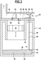
- a first embodiment of a reciprocating compressor for refrigerants according to the invention comprises a crankcase 10 in which a crank drive 12 is provided and which forms a collecting space 14 for lubricant 16, for example oil, which collects in the collecting space 14 during the lubrication of the reciprocating compressor and forms a lubricant bath 18, the surface level 20 of which varies depending on the amount of lubricant 16 in the lubricant bath 18.
- a crankcase 10 in which a crank drive 12 is provided and which forms a collecting space 14 for lubricant 16, for example oil, which collects in the collecting space 14 during the lubrication of the reciprocating compressor and forms a lubricant bath 18, the surface level 20 of which varies depending on the amount of lubricant 16 in the lubricant bath 18.
- a cylinder housing 22 is connected to the crankcase 10, in which a reciprocating piston 24, driven by the crank drive 12, can be moved up and down, whereby a cylinder chamber 26 is available for compressing refrigerant.
- the cylinder chamber 26 is closed off on its side opposite the crank drive 12 by a valve plate designated as a whole by 30, in which at least one inlet valve 32 and at least one outlet valve 34 are provided per cylinder chamber 26.
- a cylinder head 40 which extends over the valve plate 30 and in which a suction gas guide 42 extending to the inlet valve 32 and a pressure gas guide 44 leading away from the outlet valve 34 are provided, wherein the suction gas guide 42 is designed as a channel 48 leading from a suction gas connection 46 to the inlet valve 32 and, for example, running predominantly directly above the valve plate 30.
- refrigerant to be compressed is supplied to the inlet valve 32 in the valve plate 30 via the suction gas guide 42 in the cylinder head 40, namely when the reciprocating piston 24 performs a suction movement, or the refrigerant in the suction gas guide 42 remains essentially without flow, namely when the reciprocating piston 24 performs a compression movement and compresses the refrigerant in the cylinder 26 and finally expels it via the outlet valve 34 into the pressure gas guide 44.
- the suction gas guide 42 in the first embodiment is provided with a nozzle 50 in which an acceleration of a suction gas flow 52 takes place before reaching the inlet valve 32.
- an outlet opening 56 of a lubricant suction channel designated as a whole by 60, is provided, the inlet opening 62 of which is arranged in the collecting chamber 14 of the crankcase 10, specifically at a distance A from a bottom 64 of the collecting chamber 14, so that lubricant 16 can only be sucked in through the inlet opening 62 until, as in Fig. 2 shown, the surface level 20 of the lubricant bath 18 is at the level of the inlet opening 62.
- the lubricant suction channel 60 is designed as a pipe 66 which extends from the region 54 in the nozzle 50 to the inlet opening 62 and, through the position of the inlet opening 62, defines the position of the surface level 20 of the lubricant bath 18 at which it is just possible to suck in lubricant via the lubricant suction channel 60, while if the surface level 20 drops further, it is no longer possible to suck in lubricant.
- the pressure P1 in the region 54 of the suction gas stream 52 flowing through the nozzle 50 is lower than the pressure P2 in the crankcase 10, in particular in the collecting chamber 14, it is possible to suck lubricant out of the crankcase 10 via the lubricant suction channel 60 as long as the surface level 20 is higher than the inlet opening 62 and until the surface level 20 is at the level of the inlet opening 62 of the lubricant suction channel 60.
- the lubricant sucked into the nozzle 50 is fed by the suction gas flow 52 via the inlet valve 32 to the cylinder chamber 26 and is expelled from there again with the compressed refrigerant via the outlet valve 34 and thus discharged via the compressed gas guide 44, for example conveyed with the compressed gas to the next refrigerant compressor.
- the lubricant suction channel 60' is not formed by a pipe 66, but is formed in the crankcase 10, for example a wall region 70 thereof, so that the lubricant suction channel 60' runs in the wall region 70 up to the inlet opening 62, also passes through an opening 72 of the valve plate 30 and finally passes through an opening 74 of the nozzle 50, which reaches up to the outlet opening 56 in the nozzle 50.
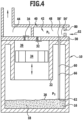
- a reciprocating compressor according to the invention shown in Fig. 4 , those parts which are identical to those of the first or second embodiment are also provided with the same reference numerals, so that reference can be made to the description thereof in full.
- the lubricant suction channel 60 runs in the pipe 66, from the inlet opening 62 to an outlet opening 56', which in this embodiment is located in the area on a side of the valve plate 30 facing the suction gas guide 42, so that the outlet opening 56' is directly adjacent to the channel 48 provided in the cylinder head 40.
- a diaphragm 80 is provided as a throttle device in relation to the suction gas flow 52 upstream of the outlet opening 56', which then, when the reciprocating piston 24 carries out a suction movement while enlarging the cylinder chamber 26, leads to a pressure drop downstream of the diaphragm 80, so that the static pressure P 1 in the area 54' between the diaphragm 80 and the inlet valve 32 drops briefly during the suction movement 24 and thus a static pressure P 1 is established, at least briefly, which is lower than the pressure P 2 in the crankcase 10, in particular in the collecting chamber 14, so that during this time during which the static pressure P 1 is lower than the static pressure P 2 lubricant is then drawn out of the lubricant via the lubricant suction channel 60. the collecting chamber 14 when the surface level 20 is above the inlet opening 62.
- the outlet opening 56 is also located on the valve plate 30, specifically in the region 54' which lies between an adjustable throttle device 90 and the inlet valve 32.
- the throttle device 90 comprises a passage 92, which can be adjusted with regard to its throttling effect for the suction gas flow 52 by means of an adjustable throttle valve 94, for example a throttle valve 94 pivotable about an axis 96, wherein, for example, an actuator 98 is provided.
- an adjustable throttle valve 94 for example a throttle valve 94 pivotable about an axis 96, wherein, for example, an actuator 98 is provided.
- this allows the same effect to be achieved as with the orifice 80, but with the difference that the throttle device 90 can be adjusted in terms of its throttling effect on the suction gas flow 52 by turning the throttle valve 94, so that it is possible to adjust the pressure P 1 , namely in accordance with the suction gas flow 52, so that, for example, during certain partial phases of the suction movement of the reciprocating piston 24, the static pressure P 1 drops to such an extent that it is lower than the static pressure P 2 in the Crankcase 10, in particular in the collecting chamber 14, and thus it is possible to suck lubricant out of the collecting chamber 14 and supply it to the suction gas stream 52 for further transport.
- This solution has the advantage that, due to the adjustability of the throttle valve 94 by means of the actuator 98 according to the operating conditions of the reciprocating compressor, the time periods at which the static pressure P 1 in the channel 48 is lower than the static pressure P 2 in the crankcase 10, in particular in the collecting chamber 14 thereof, can be adjusted in each case in adaptation to the suction gas flow 52.
- the variant of the third embodiment described above thus provides that the setting of the throttle valve 94 remains constant over a large number of working cycles and thus the setting can be made such that at least temporarily the static pressure P1 drops to such an extent that lubricant 16 is sucked in via the lubricant suction channel 60.
- throttle valve 94 dynamically, i.e., for example, to adjust the throttle valve 94 to a specific value for throttling the suction gas flow 52 during each working cycle in order to reduce the static pressure P1 in the region 54' for a specific period of time.
Landscapes
- Engineering & Computer Science (AREA)
- Mechanical Engineering (AREA)
- General Engineering & Computer Science (AREA)
- Compressor (AREA)
- Compressors, Vaccum Pumps And Other Relevant Systems (AREA)
Claims (10)
- Circuit de refroidissement avec plusieurs étages de compresseur, dans lequel un étage de compresseur est installé comme compresseur à pistons alternatifs dans le circuit de refroidissement et comprend ce qui suit, un carter de vilebrequin (10) dans lequel est disposée une chambre collectrice (14) pour lubrifiants (16), un carter de cylindre (22) dans lequel au moins un piston alternatif (24) est mobile de manière oscillante, une plaque porte-soupape (30) terminant le carter de cylindre (22), dans laquelle sont disposées au moins une valve d'admission (32) et une soupape d'échappement (34), et une tête de cylindre (40) dans laquelle sont prévues une conduite de gaz d'aspiration (42) dirigée vers la valve d'admission (32) et une conduite de gaz sous pression (44) s'éloignant de la soupape d'échappement (34),
dans lequel un canal d'aspiration (60) de lubrifiant est prévu, lequel présente un orifice d'admission (62) affecté à la chambre collectrice (14) et un orifice d'admission (56) affecté à la conduite de gaz d'aspiration (42), dans lequel l'orifice d'admission (62) est agencé dans la chambre collectrice (14) de sorte qu'il prédéfinisse une position prédéterminée d'un niveau superficiel (20) d'un bain de lubrifiant (18), et dans lequel l'orifice d'échappement (56) se trouve dans une zone (54) de la conduite de gaz d'aspiration (42), dans laquelle il règne une pression statique (P1) au moins temporairement, laquelle est inférieure à une pression statique (P2) dans la chambre collectrice (14) pour du lubrifiant (16) de sorte que du lubrifiant soit aspiré de la chambre collectrice (14) et soit amené au gaz d'aspiration qui achemine alors ce lubrifiant à travers le compresseur à pistons alternatifs et le transporte plus loin par l'intermédiaire d'une conduite de gaz sous pression dans le circuit de refroidissement vers le compresseur suivant dans le circuit de refroidissement. - Circuit de refroidissement selon la revendication 1, caractérisé en ce que l'orifice d'admission (62) du canal d'aspiration de lubrifiant (60) prédéfinit un niveau superficiel (20) le plus bas pouvant être atteint par aspiration de lubrifiant (16) par l'intermédiaire du canal d'aspiration de lubrifiant (60) du bain de lubrifiant (18).
- Circuit de refroidissement selon l'une quelconque des revendications précédentes, caractérisé en ce que le canal d'aspiration de lubrifiant (60) passe, du moins par endroits, par un tube (66) dépassant à l'intérieur du carter de vilebrequin (10).
- Circuit de refroidissement selon la revendication 3, caractérisé en ce que le tube (66) présente l'orifice d'admission (62).
- Circuit de refroidissement selon l'une quelconque des revendications précédentes, caractérisé en ce que le canal d'aspiration de lubrifiant (60) passe, du moins par endroits, dans le carter de vilebrequin (10).
- Circuit de refroidissement selon l'une quelconque des revendications précédentes, caractérisé en ce que la zone (54) présentant l'orifice d'échappement (56) du canal d'aspiration de lubrifiant (60) se trouve dans un rétrécissement d'une buse (50).
- Circuit de refroidissement selon l'une quelconque des revendications 1 à 5, caractérisé en ce que la zone (54) de la conduite de gaz d'aspiration (42) présentant l'orifice d'échappement (56) du canal d'aspiration de lubrifiant (60) se trouve derrière un dispositif d'étranglement (80, 90) dans la conduite de gaz d'aspiration (42) dans le sens d'écoulement du flux de gaz d'aspiration (42).
- Circuit de refroidissement selon la revendication 7, caractérisé en ce que le dispositif d'étranglement est conçu comme un diaphragme (80).
- Circuit de refroidissement selon la revendication 7, caractérisé en ce que le dispositif d'étranglement est un dispositif d'étranglement réglable (90).
- Circuit de refroidissement selon la revendication 9, caractérisé en ce que le dispositif d'étranglement (90) réglable bascule entre des intervalles de temps sans étranglement et des intervalles de temps avec étranglement.
Applications Claiming Priority (3)
| Application Number | Priority Date | Filing Date | Title |
|---|---|---|---|
| DE102008004569A DE102008004569A1 (de) | 2008-01-10 | 2008-01-10 | Hubkolbenverdichter |
| EP08869359.3A EP2229532B1 (fr) | 2008-01-10 | 2008-12-30 | Compresseur à piston |
| PCT/EP2008/068357 WO2009087071A1 (fr) | 2008-01-10 | 2008-12-30 | Compresseur à piston |
Related Parent Applications (1)
| Application Number | Title | Priority Date | Filing Date |
|---|---|---|---|
| EP08869359.3A Division EP2229532B1 (fr) | 2008-01-10 | 2008-12-30 | Compresseur à piston |
Publications (2)
| Publication Number | Publication Date |
|---|---|
| EP3557056A1 EP3557056A1 (fr) | 2019-10-23 |
| EP3557056B1 true EP3557056B1 (fr) | 2024-11-06 |
Family
ID=40461769
Family Applications (2)
| Application Number | Title | Priority Date | Filing Date |
|---|---|---|---|
| EP08869359.3A Active EP2229532B1 (fr) | 2008-01-10 | 2008-12-30 | Compresseur à piston |
| EP19176434.9A Active EP3557056B1 (fr) | 2008-01-10 | 2008-12-30 | Circuit frigorifique à plusieurs étages de compresseur |
Family Applications Before (1)
| Application Number | Title | Priority Date | Filing Date |
|---|---|---|---|
| EP08869359.3A Active EP2229532B1 (fr) | 2008-01-10 | 2008-12-30 | Compresseur à piston |
Country Status (6)
| Country | Link |
|---|---|
| US (1) | US8690545B2 (fr) |
| EP (2) | EP2229532B1 (fr) |
| CN (1) | CN101910630B (fr) |
| DE (1) | DE102008004569A1 (fr) |
| TR (1) | TR201909111T4 (fr) |
| WO (1) | WO2009087071A1 (fr) |
Families Citing this family (9)
| Publication number | Priority date | Publication date | Assignee | Title |
|---|---|---|---|---|
| DE102013203268A1 (de) * | 2013-02-27 | 2014-08-28 | Bitzer Kühlmaschinenbau Gmbh | Kältemittelverdichteranlage |
| FR3009896A1 (fr) | 2013-08-20 | 2015-02-27 | Commissariat Energie Atomique | Electrolyte liquide pour accumulateur au lithium-ion, accumulateur au lithium-ion et procede de charge d'un accumulateur lithium-ion |
| DE102015103730A1 (de) | 2015-03-13 | 2016-09-15 | Bitzer Kühlmaschinenbau Gmbh | Kältemittelverdichteranlage |
| JP2017198406A (ja) * | 2016-04-28 | 2017-11-02 | 株式会社デンソー | 減圧装置および冷凍サイクル装置 |
| WO2020075128A1 (fr) * | 2018-10-12 | 2020-04-16 | Officine Mario Dorin S.P.A. | Compresseur alternatif pour système de réfrigération et/ou de conditionnement et/ou de pompe à chaleur |
| GB2587663B (en) * | 2019-10-04 | 2021-11-03 | Ernest H Hill Ltd | Improvements to pumps and compressors |
| NL2031315B1 (en) * | 2022-03-17 | 2023-09-29 | Gea Refrigeration Netherlands N V | A compressor assembly |
| CN115182870B (zh) * | 2022-07-18 | 2024-01-16 | 西南石油大学 | 一种用于往复式压缩缸的流线型气道结构 |
| KR102825391B1 (ko) * | 2022-11-04 | 2025-07-02 | 노상인 | 낮은 소음과 향상된 윤활성을 가지는 압축기 |
Family Cites Families (25)
| Publication number | Priority date | Publication date | Assignee | Title |
|---|---|---|---|---|
| GB237323A (en) * | 1924-03-28 | 1925-07-28 | Henry Selby Hele Shaw | Improvements in rotary air compressors |
| US1795445A (en) * | 1927-11-21 | 1931-03-10 | Walter G E Rolaff | Reciprocating compressor |
| US2023435A (en) * | 1928-07-06 | 1935-12-10 | Servel Inc | Refrigeration |
| US2054097A (en) * | 1932-05-31 | 1936-09-15 | James B Replogle | Harmonic compressor |
| US2128065A (en) * | 1935-09-04 | 1938-08-23 | Westinghouse Air Brake Co | Compressor lubricator |
| US2155051A (en) * | 1937-06-03 | 1939-04-18 | Sulzer Ag | Apparatus for the compression of gases |
| US2150487A (en) * | 1938-06-04 | 1939-03-14 | Carrier Corp | Compressor apparatus |
| US2233168A (en) * | 1939-04-19 | 1941-02-25 | Gen Electric | Compressor |
| US2629538A (en) * | 1948-05-06 | 1953-02-24 | James B Replogle | Oscillating electrical compressor |
| DE1044839B (de) * | 1956-01-23 | 1958-11-27 | Licentia Gmbh | Anordnung zur Schmierung eines gekapselten Schwingkompressors, insbesondere fuer Kaeltemaschinen |
| DE1972144U (de) * | 1967-03-31 | 1967-11-09 | Otto Boge Fa | Vakuumpumpe. |
| GB1244105A (en) * | 1969-02-04 | 1971-08-25 | Bitzer Kuehlmaschb G M B H | Reciprocating piston compressors |
| US3746477A (en) * | 1970-05-01 | 1973-07-17 | Tokyo Shibaura Electric Co | Rotary compressor |
| US3713513A (en) * | 1971-06-10 | 1973-01-30 | Fedders Corp | Crankcase evacuation and oil return system |
| HK40578A (en) * | 1972-10-04 | 1978-07-21 | Mitchell Co John E | Refrigeration compressor |
| DE2402029B2 (de) * | 1974-01-17 | 1980-04-24 | 1000 Berlin | Schmiervorrichtung für Rotationskolbenverdichter |
| US4127363A (en) * | 1976-12-16 | 1978-11-28 | Kabushiki Kaisha Toyoda Jidoshokki Seisakusho | Swash-plate type compressor |
| JPS5732084A (en) * | 1980-07-31 | 1982-02-20 | Diesel Kiki Co Ltd | Swash plate type compressor |
| US4613284A (en) * | 1985-09-03 | 1986-09-23 | Iosif Baumberg | Apparatus for elevating liquids including a Venturi pipe and a liquid delay element |
| DE4134184A1 (de) * | 1991-10-16 | 1993-04-22 | Bosch Gmbh Robert | Verstellbare hydrostatische pumpe |
| US5190121A (en) * | 1991-10-31 | 1993-03-02 | General Motors Corporation | Two phase compressor lubrication |
| DE4320541A1 (de) * | 1993-06-21 | 1994-12-22 | Wagner Gmbh J | Vorrichtung zum Verspritzen von Spritzgut unter hohem Druck |
| US5347821A (en) * | 1993-07-23 | 1994-09-20 | American Standard Inc. | Apparatus and method of oil charge loss protection for compressors |
| DE4445957A1 (de) * | 1994-12-22 | 1996-06-27 | Abb Management Ag | Verfahren und Vorrichtung zur Eigenschmierung der Wälzlager von Turbomaschinen |
| DE10358471A1 (de) * | 2003-11-17 | 2005-06-23 | Bitzer Kühlmaschinenbau Gmbh | Kältemittelverdichter für Kraftfahrzeuge |
-
2008
- 2008-01-10 DE DE102008004569A patent/DE102008004569A1/de not_active Ceased
- 2008-12-30 WO PCT/EP2008/068357 patent/WO2009087071A1/fr not_active Ceased
- 2008-12-30 EP EP08869359.3A patent/EP2229532B1/fr active Active
- 2008-12-30 EP EP19176434.9A patent/EP3557056B1/fr active Active
- 2008-12-30 CN CN200880124472.0A patent/CN101910630B/zh active Active
-
2009
- 2009-12-30 TR TR2019/09111T patent/TR201909111T4/tr unknown
-
2010
- 2010-07-07 US US12/831,508 patent/US8690545B2/en active Active
Also Published As
| Publication number | Publication date |
|---|---|
| CN101910630A (zh) | 2010-12-08 |
| EP2229532A1 (fr) | 2010-09-22 |
| US20110005266A1 (en) | 2011-01-13 |
| US8690545B2 (en) | 2014-04-08 |
| EP2229532B1 (fr) | 2019-05-29 |
| CN101910630B (zh) | 2014-01-01 |
| WO2009087071A1 (fr) | 2009-07-16 |
| DE102008004569A1 (de) | 2009-07-16 |
| EP3557056A1 (fr) | 2019-10-23 |
| TR201909111T4 (tr) | 2019-07-22 |
Similar Documents
| Publication | Publication Date | Title |
|---|---|---|
| EP2229532B1 (fr) | Compresseur à piston | |
| EP2064446B1 (fr) | Compresseur comprenant un piston maintenu sous l'effet de la pression d'un gaz | |
| DE4008882C2 (fr) | ||
| DE3718651A1 (de) | Stroemungsteiler | |
| DE102014118266B3 (de) | Kompressorvorrichtung mit separatem Luftentölelement | |
| EP0758054A1 (fr) | Système de circulation d'huile pour un compresseur à vis | |
| DE2650935A1 (de) | Gekapselte kaeltemaschine | |
| DE68906511T2 (de) | In-line-filtereinrichtung fuer druckluft. | |
| EP3657017B1 (fr) | Compresseur frigorifique | |
| EP2961985B1 (fr) | Installation de compression d'un réfrigérant | |
| EP3209883B1 (fr) | Silencieux d'aspiration pour un compresseur frigorifique à enceinte hermétique | |
| DE69303447T2 (de) | Vakuumpumpgerät | |
| DE102015122443B4 (de) | Kältemittelverdichteranlage | |
| EP4288665A1 (fr) | Compresseur, en particulier compresseur frigorifique, machine de froid, et procédé de fabrication d'un compresseur | |
| EP3377764B1 (fr) | Purgeur d'eau à commande pneumatique | |
| AT525559B1 (de) | Kolbenkompressor mit reduziertem Kurbelgehäuseinnendruck | |
| DE102008025322B4 (de) | Kältemittelverdichter | |
| DE898918C (de) | Verfahren und Vorrichtung zur Schmierung, Filterung und Geraeuschdaempfung bei Kaeltemaschinen | |
| DE9305554U1 (de) | Zweifach-Verdrängerpumpe | |
| DE2650936B1 (de) | Gekapselte Kaeltemaschine | |
| DE102016217440A1 (de) | Abscheideeinrichtung | |
| DE919593C (de) | Schmiermittelzufuehrung fuer Kaeltemaschinen | |
| DE60033049T2 (de) | Kühlkreislauf | |
| DE10142540A1 (de) | Taumelscheibenkompressor | |
| DE102016217442A1 (de) | Brennkraftmaschine |
Legal Events
| Date | Code | Title | Description |
|---|---|---|---|
| PUAI | Public reference made under article 153(3) epc to a published international application that has entered the european phase |
Free format text: ORIGINAL CODE: 0009012 |
|
| STAA | Information on the status of an ep patent application or granted ep patent |
Free format text: STATUS: THE APPLICATION HAS BEEN PUBLISHED |
|
| AC | Divisional application: reference to earlier application |
Ref document number: 2229532 Country of ref document: EP Kind code of ref document: P |
|
| AK | Designated contracting states |
Kind code of ref document: A1 Designated state(s): AT BE BG CH CY CZ DE DK EE ES FI FR GB GR HR HU IE IS IT LI LT LU LV MC MT NL NO PL PT RO SE SI SK TR |
|
| STAA | Information on the status of an ep patent application or granted ep patent |
Free format text: STATUS: REQUEST FOR EXAMINATION WAS MADE |
|
| 17P | Request for examination filed |
Effective date: 20200319 |
|
| RBV | Designated contracting states (corrected) |
Designated state(s): AT BE BG CH CY CZ DE DK EE ES FI FR GB GR HR HU IE IS IT LI LT LU LV MC MT NL NO PL PT RO SE SI SK TR |
|
| STAA | Information on the status of an ep patent application or granted ep patent |
Free format text: STATUS: EXAMINATION IS IN PROGRESS |
|
| 17Q | First examination report despatched |
Effective date: 20220304 |
|
| P01 | Opt-out of the competence of the unified patent court (upc) registered |
Effective date: 20230517 |
|
| GRAP | Despatch of communication of intention to grant a patent |
Free format text: ORIGINAL CODE: EPIDOSNIGR1 |
|
| STAA | Information on the status of an ep patent application or granted ep patent |
Free format text: STATUS: GRANT OF PATENT IS INTENDED |
|
| RIC1 | Information provided on ipc code assigned before grant |
Ipc: F04B 39/12 20060101ALI20231206BHEP Ipc: F04B 39/02 20060101AFI20231206BHEP |
|
| INTG | Intention to grant announced |
Effective date: 20240104 |
|
| GRAJ | Information related to disapproval of communication of intention to grant by the applicant or resumption of examination proceedings by the epo deleted |
Free format text: ORIGINAL CODE: EPIDOSDIGR1 |
|
| STAA | Information on the status of an ep patent application or granted ep patent |
Free format text: STATUS: EXAMINATION IS IN PROGRESS |
|
| GRAP | Despatch of communication of intention to grant a patent |
Free format text: ORIGINAL CODE: EPIDOSNIGR1 |
|
| STAA | Information on the status of an ep patent application or granted ep patent |
Free format text: STATUS: GRANT OF PATENT IS INTENDED |
|
| INTC | Intention to grant announced (deleted) | ||
| INTG | Intention to grant announced |
Effective date: 20240529 |
|
| GRAS | Grant fee paid |
Free format text: ORIGINAL CODE: EPIDOSNIGR3 |
|
| GRAA | (expected) grant |
Free format text: ORIGINAL CODE: 0009210 |
|
| STAA | Information on the status of an ep patent application or granted ep patent |
Free format text: STATUS: THE PATENT HAS BEEN GRANTED |
|
| AC | Divisional application: reference to earlier application |
Ref document number: 2229532 Country of ref document: EP Kind code of ref document: P |
|
| AK | Designated contracting states |
Kind code of ref document: B1 Designated state(s): AT BE BG CH CY CZ DE DK EE ES FI FR GB GR HR HU IE IS IT LI LT LU LV MC MT NL NO PL PT RO SE SI SK TR |
|
| REG | Reference to a national code |
Ref country code: GB Ref legal event code: FG4D Free format text: NOT ENGLISH |
|
| REG | Reference to a national code |
Ref country code: CH Ref legal event code: EP |
|
| REG | Reference to a national code |
Ref country code: DE Ref legal event code: R096 Ref document number: 502008017275 Country of ref document: DE |
|
| REG | Reference to a national code |
Ref country code: IE Ref legal event code: FG4D Free format text: LANGUAGE OF EP DOCUMENT: GERMAN |
|
| REG | Reference to a national code |
Ref country code: LT Ref legal event code: MG9D |
|
| REG | Reference to a national code |
Ref country code: NL Ref legal event code: MP Effective date: 20241106 |
|
| PG25 | Lapsed in a contracting state [announced via postgrant information from national office to epo] |
Ref country code: HR Free format text: LAPSE BECAUSE OF FAILURE TO SUBMIT A TRANSLATION OF THE DESCRIPTION OR TO PAY THE FEE WITHIN THE PRESCRIBED TIME-LIMIT Effective date: 20241106 Ref country code: IS Free format text: LAPSE BECAUSE OF FAILURE TO SUBMIT A TRANSLATION OF THE DESCRIPTION OR TO PAY THE FEE WITHIN THE PRESCRIBED TIME-LIMIT Effective date: 20250306 Ref country code: PT Free format text: LAPSE BECAUSE OF FAILURE TO SUBMIT A TRANSLATION OF THE DESCRIPTION OR TO PAY THE FEE WITHIN THE PRESCRIBED TIME-LIMIT Effective date: 20250306 |
|
| PG25 | Lapsed in a contracting state [announced via postgrant information from national office to epo] |
Ref country code: FI Free format text: LAPSE BECAUSE OF FAILURE TO SUBMIT A TRANSLATION OF THE DESCRIPTION OR TO PAY THE FEE WITHIN THE PRESCRIBED TIME-LIMIT Effective date: 20241106 Ref country code: NL Free format text: LAPSE BECAUSE OF FAILURE TO SUBMIT A TRANSLATION OF THE DESCRIPTION OR TO PAY THE FEE WITHIN THE PRESCRIBED TIME-LIMIT Effective date: 20241106 |
|
| PG25 | Lapsed in a contracting state [announced via postgrant information from national office to epo] |
Ref country code: BG Free format text: LAPSE BECAUSE OF FAILURE TO SUBMIT A TRANSLATION OF THE DESCRIPTION OR TO PAY THE FEE WITHIN THE PRESCRIBED TIME-LIMIT Effective date: 20241106 |
|
| PG25 | Lapsed in a contracting state [announced via postgrant information from national office to epo] |
Ref country code: ES Free format text: LAPSE BECAUSE OF FAILURE TO SUBMIT A TRANSLATION OF THE DESCRIPTION OR TO PAY THE FEE WITHIN THE PRESCRIBED TIME-LIMIT Effective date: 20241106 |
|
| PG25 | Lapsed in a contracting state [announced via postgrant information from national office to epo] |
Ref country code: NO Free format text: LAPSE BECAUSE OF FAILURE TO SUBMIT A TRANSLATION OF THE DESCRIPTION OR TO PAY THE FEE WITHIN THE PRESCRIBED TIME-LIMIT Effective date: 20250206 |
|
| PG25 | Lapsed in a contracting state [announced via postgrant information from national office to epo] |
Ref country code: GR Free format text: LAPSE BECAUSE OF FAILURE TO SUBMIT A TRANSLATION OF THE DESCRIPTION OR TO PAY THE FEE WITHIN THE PRESCRIBED TIME-LIMIT Effective date: 20250207 Ref country code: LV Free format text: LAPSE BECAUSE OF FAILURE TO SUBMIT A TRANSLATION OF THE DESCRIPTION OR TO PAY THE FEE WITHIN THE PRESCRIBED TIME-LIMIT Effective date: 20241106 |
|
| PG25 | Lapsed in a contracting state [announced via postgrant information from national office to epo] |
Ref country code: PL Free format text: LAPSE BECAUSE OF FAILURE TO SUBMIT A TRANSLATION OF THE DESCRIPTION OR TO PAY THE FEE WITHIN THE PRESCRIBED TIME-LIMIT Effective date: 20241106 |
|
| PG25 | Lapsed in a contracting state [announced via postgrant information from national office to epo] |
Ref country code: DK Free format text: LAPSE BECAUSE OF FAILURE TO SUBMIT A TRANSLATION OF THE DESCRIPTION OR TO PAY THE FEE WITHIN THE PRESCRIBED TIME-LIMIT Effective date: 20241106 |
|
| PG25 | Lapsed in a contracting state [announced via postgrant information from national office to epo] |
Ref country code: EE Free format text: LAPSE BECAUSE OF FAILURE TO SUBMIT A TRANSLATION OF THE DESCRIPTION OR TO PAY THE FEE WITHIN THE PRESCRIBED TIME-LIMIT Effective date: 20241106 |
|
| PG25 | Lapsed in a contracting state [announced via postgrant information from national office to epo] |
Ref country code: RO Free format text: LAPSE BECAUSE OF FAILURE TO SUBMIT A TRANSLATION OF THE DESCRIPTION OR TO PAY THE FEE WITHIN THE PRESCRIBED TIME-LIMIT Effective date: 20241106 |
|
| PG25 | Lapsed in a contracting state [announced via postgrant information from national office to epo] |
Ref country code: SK Free format text: LAPSE BECAUSE OF FAILURE TO SUBMIT A TRANSLATION OF THE DESCRIPTION OR TO PAY THE FEE WITHIN THE PRESCRIBED TIME-LIMIT Effective date: 20241106 |
|
| PG25 | Lapsed in a contracting state [announced via postgrant information from national office to epo] |
Ref country code: CZ Free format text: LAPSE BECAUSE OF FAILURE TO SUBMIT A TRANSLATION OF THE DESCRIPTION OR TO PAY THE FEE WITHIN THE PRESCRIBED TIME-LIMIT Effective date: 20241106 |
|
| REG | Reference to a national code |
Ref country code: CH Ref legal event code: PL |
|
| REG | Reference to a national code |
Ref country code: DE Ref legal event code: R097 Ref document number: 502008017275 Country of ref document: DE |
|
| PG25 | Lapsed in a contracting state [announced via postgrant information from national office to epo] |
Ref country code: LU Free format text: LAPSE BECAUSE OF NON-PAYMENT OF DUE FEES Effective date: 20241230 |
|
| PG25 | Lapsed in a contracting state [announced via postgrant information from national office to epo] |
Ref country code: SE Free format text: LAPSE BECAUSE OF FAILURE TO SUBMIT A TRANSLATION OF THE DESCRIPTION OR TO PAY THE FEE WITHIN THE PRESCRIBED TIME-LIMIT Effective date: 20241106 |
|
| PLBE | No opposition filed within time limit |
Free format text: ORIGINAL CODE: 0009261 |
|
| STAA | Information on the status of an ep patent application or granted ep patent |
Free format text: STATUS: NO OPPOSITION FILED WITHIN TIME LIMIT |
|
| PG25 | Lapsed in a contracting state [announced via postgrant information from national office to epo] |
Ref country code: MC Free format text: LAPSE BECAUSE OF FAILURE TO SUBMIT A TRANSLATION OF THE DESCRIPTION OR TO PAY THE FEE WITHIN THE PRESCRIBED TIME-LIMIT Effective date: 20241106 |
|
| REG | Reference to a national code |
Ref country code: BE Ref legal event code: MM Effective date: 20241231 |
|
| 26N | No opposition filed |
Effective date: 20250807 |
|
| PGFP | Annual fee paid to national office [announced via postgrant information from national office to epo] |
Ref country code: TR Payment date: 20250929 Year of fee payment: 18 Ref country code: IT Payment date: 20250929 Year of fee payment: 18 |
|
| PG25 | Lapsed in a contracting state [announced via postgrant information from national office to epo] |
Ref country code: BE Free format text: LAPSE BECAUSE OF NON-PAYMENT OF DUE FEES Effective date: 20241231 |
|
| PGFP | Annual fee paid to national office [announced via postgrant information from national office to epo] |
Ref country code: FR Payment date: 20250926 Year of fee payment: 18 |
|
| PG25 | Lapsed in a contracting state [announced via postgrant information from national office to epo] |
Ref country code: CH Free format text: LAPSE BECAUSE OF NON-PAYMENT OF DUE FEES Effective date: 20241231 |
|
| PG25 | Lapsed in a contracting state [announced via postgrant information from national office to epo] |
Ref country code: IE Free format text: LAPSE BECAUSE OF NON-PAYMENT OF DUE FEES Effective date: 20241230 |
|
| PGFP | Annual fee paid to national office [announced via postgrant information from national office to epo] |
Ref country code: DE Payment date: 20250926 Year of fee payment: 18 |
|
| PGFP | Annual fee paid to national office [announced via postgrant information from national office to epo] |
Ref country code: GB Payment date: 20251223 Year of fee payment: 18 |
|
| REG | Reference to a national code |
Ref country code: AT Ref legal event code: MM01 Ref document number: 1739595 Country of ref document: AT Kind code of ref document: T Effective date: 20241230 |
|
| PG25 | Lapsed in a contracting state [announced via postgrant information from national office to epo] |
Ref country code: AT Free format text: LAPSE BECAUSE OF NON-PAYMENT OF DUE FEES Effective date: 20241230 |
|
| PG25 | Lapsed in a contracting state [announced via postgrant information from national office to epo] |
Ref country code: CY Free format text: LAPSE BECAUSE OF FAILURE TO SUBMIT A TRANSLATION OF THE DESCRIPTION OR TO PAY THE FEE WITHIN THE PRESCRIBED TIME-LIMIT Effective date: 20241106 |
|
| PG25 | Lapsed in a contracting state [announced via postgrant information from national office to epo] |
Ref country code: HU Free format text: LAPSE BECAUSE OF FAILURE TO SUBMIT A TRANSLATION OF THE DESCRIPTION OR TO PAY THE FEE WITHIN THE PRESCRIBED TIME-LIMIT; INVALID AB INITIO Effective date: 20081230 |
|
| PG25 | Lapsed in a contracting state [announced via postgrant information from national office to epo] |
Ref country code: SI Free format text: LAPSE BECAUSE OF FAILURE TO SUBMIT A TRANSLATION OF THE DESCRIPTION OR TO PAY THE FEE WITHIN THE PRESCRIBED TIME-LIMIT Effective date: 20241106 |
|
| PG25 | Lapsed in a contracting state [announced via postgrant information from national office to epo] |
Ref country code: LT Free format text: LAPSE BECAUSE OF FAILURE TO SUBMIT A TRANSLATION OF THE DESCRIPTION OR TO PAY THE FEE WITHIN THE PRESCRIBED TIME-LIMIT Effective date: 20241106 |