EP3557280A1 - Vorrichtung und verfahren zur erzeugung von karten, die eine umgebung eines fahrzeugs darstellen - Google Patents
Vorrichtung und verfahren zur erzeugung von karten, die eine umgebung eines fahrzeugs darstellen Download PDFInfo
- Publication number
- EP3557280A1 EP3557280A1 EP18167990.3A EP18167990A EP3557280A1 EP 3557280 A1 EP3557280 A1 EP 3557280A1 EP 18167990 A EP18167990 A EP 18167990A EP 3557280 A1 EP3557280 A1 EP 3557280A1
- Authority
- EP
- European Patent Office
- Prior art keywords
- type
- polarization
- radar
- vehicle
- radar sensor
- Prior art date
- Legal status (The legal status is an assumption and is not a legal conclusion. Google has not performed a legal analysis and makes no representation as to the accuracy of the status listed.)
- Granted
Links
Images

Classifications
-
- G—PHYSICS
- G01—MEASURING; TESTING
- G01S—RADIO DIRECTION-FINDING; RADIO NAVIGATION; DETERMINING DISTANCE OR VELOCITY BY USE OF RADIO WAVES; LOCATING OR PRESENCE-DETECTING BY USE OF THE REFLECTION OR RERADIATION OF RADIO WAVES; ANALOGOUS ARRANGEMENTS USING OTHER WAVES
- G01S13/00—Systems using the reflection or reradiation of radio waves, e.g. radar systems; Analogous systems using reflection or reradiation of waves whose nature or wavelength is irrelevant or unspecified
- G01S13/87—Combinations of radar systems, e.g. primary radar and secondary radar
-
- G—PHYSICS
- G01—MEASURING; TESTING
- G01S—RADIO DIRECTION-FINDING; RADIO NAVIGATION; DETERMINING DISTANCE OR VELOCITY BY USE OF RADIO WAVES; LOCATING OR PRESENCE-DETECTING BY USE OF THE REFLECTION OR RERADIATION OF RADIO WAVES; ANALOGOUS ARRANGEMENTS USING OTHER WAVES
- G01S13/00—Systems using the reflection or reradiation of radio waves, e.g. radar systems; Analogous systems using reflection or reradiation of waves whose nature or wavelength is irrelevant or unspecified
- G01S13/88—Radar or analogous systems specially adapted for specific applications
- G01S13/89—Radar or analogous systems specially adapted for specific applications for mapping or imaging
-
- G—PHYSICS
- G01—MEASURING; TESTING
- G01S—RADIO DIRECTION-FINDING; RADIO NAVIGATION; DETERMINING DISTANCE OR VELOCITY BY USE OF RADIO WAVES; LOCATING OR PRESENCE-DETECTING BY USE OF THE REFLECTION OR RERADIATION OF RADIO WAVES; ANALOGOUS ARRANGEMENTS USING OTHER WAVES
- G01S13/00—Systems using the reflection or reradiation of radio waves, e.g. radar systems; Analogous systems using reflection or reradiation of waves whose nature or wavelength is irrelevant or unspecified
- G01S13/88—Radar or analogous systems specially adapted for specific applications
- G01S13/93—Radar or analogous systems specially adapted for specific applications for anti-collision purposes
- G01S13/931—Radar or analogous systems specially adapted for specific applications for anti-collision purposes of land vehicles
-
- G—PHYSICS
- G01—MEASURING; TESTING
- G01S—RADIO DIRECTION-FINDING; RADIO NAVIGATION; DETERMINING DISTANCE OR VELOCITY BY USE OF RADIO WAVES; LOCATING OR PRESENCE-DETECTING BY USE OF THE REFLECTION OR RERADIATION OF RADIO WAVES; ANALOGOUS ARRANGEMENTS USING OTHER WAVES
- G01S7/00—Details of systems according to groups G01S13/00, G01S15/00, G01S17/00
- G01S7/02—Details of systems according to groups G01S13/00, G01S15/00, G01S17/00 of systems according to group G01S13/00
- G01S7/024—Details of systems according to groups G01S13/00, G01S15/00, G01S17/00 of systems according to group G01S13/00 using polarisation effects
- G01S7/025—Details of systems according to groups G01S13/00, G01S15/00, G01S17/00 of systems according to group G01S13/00 using polarisation effects involving the transmission of linearly polarised waves
-
- G—PHYSICS
- G01—MEASURING; TESTING
- G01S—RADIO DIRECTION-FINDING; RADIO NAVIGATION; DETERMINING DISTANCE OR VELOCITY BY USE OF RADIO WAVES; LOCATING OR PRESENCE-DETECTING BY USE OF THE REFLECTION OR RERADIATION OF RADIO WAVES; ANALOGOUS ARRANGEMENTS USING OTHER WAVES
- G01S7/00—Details of systems according to groups G01S13/00, G01S15/00, G01S17/00
- G01S7/02—Details of systems according to groups G01S13/00, G01S15/00, G01S17/00 of systems according to group G01S13/00
- G01S7/024—Details of systems according to groups G01S13/00, G01S15/00, G01S17/00 of systems according to group G01S13/00 using polarisation effects
- G01S7/026—Details of systems according to groups G01S13/00, G01S15/00, G01S17/00 of systems according to group G01S13/00 using polarisation effects involving the transmission of elliptically or circularly polarised waves
-
- G—PHYSICS
- G01—MEASURING; TESTING
- G01S—RADIO DIRECTION-FINDING; RADIO NAVIGATION; DETERMINING DISTANCE OR VELOCITY BY USE OF RADIO WAVES; LOCATING OR PRESENCE-DETECTING BY USE OF THE REFLECTION OR RERADIATION OF RADIO WAVES; ANALOGOUS ARRANGEMENTS USING OTHER WAVES
- G01S7/00—Details of systems according to groups G01S13/00, G01S15/00, G01S17/00
- G01S7/02—Details of systems according to groups G01S13/00, G01S15/00, G01S17/00 of systems according to group G01S13/00
- G01S7/41—Details of systems according to groups G01S13/00, G01S15/00, G01S17/00 of systems according to group G01S13/00 using analysis of echo signal for target characterisation; Target signature; Target cross-section
- G01S7/411—Identification of targets based on measurements of radar reflectivity
-
- G—PHYSICS
- G01—MEASURING; TESTING
- G01S—RADIO DIRECTION-FINDING; RADIO NAVIGATION; DETERMINING DISTANCE OR VELOCITY BY USE OF RADIO WAVES; LOCATING OR PRESENCE-DETECTING BY USE OF THE REFLECTION OR RERADIATION OF RADIO WAVES; ANALOGOUS ARRANGEMENTS USING OTHER WAVES
- G01S13/00—Systems using the reflection or reradiation of radio waves, e.g. radar systems; Analogous systems using reflection or reradiation of waves whose nature or wavelength is irrelevant or unspecified
- G01S13/003—Bistatic radar systems; Multistatic radar systems
-
- G—PHYSICS
- G01—MEASURING; TESTING
- G01S—RADIO DIRECTION-FINDING; RADIO NAVIGATION; DETERMINING DISTANCE OR VELOCITY BY USE OF RADIO WAVES; LOCATING OR PRESENCE-DETECTING BY USE OF THE REFLECTION OR RERADIATION OF RADIO WAVES; ANALOGOUS ARRANGEMENTS USING OTHER WAVES
- G01S13/00—Systems using the reflection or reradiation of radio waves, e.g. radar systems; Analogous systems using reflection or reradiation of waves whose nature or wavelength is irrelevant or unspecified
- G01S13/87—Combinations of radar systems, e.g. primary radar and secondary radar
- G01S13/878—Combination of several spaced transmitters or receivers of known location for determining the position of a transponder or a reflector
-
- G—PHYSICS
- G01—MEASURING; TESTING
- G01S—RADIO DIRECTION-FINDING; RADIO NAVIGATION; DETERMINING DISTANCE OR VELOCITY BY USE OF RADIO WAVES; LOCATING OR PRESENCE-DETECTING BY USE OF THE REFLECTION OR RERADIATION OF RADIO WAVES; ANALOGOUS ARRANGEMENTS USING OTHER WAVES
- G01S13/00—Systems using the reflection or reradiation of radio waves, e.g. radar systems; Analogous systems using reflection or reradiation of waves whose nature or wavelength is irrelevant or unspecified
- G01S13/88—Radar or analogous systems specially adapted for specific applications
- G01S13/93—Radar or analogous systems specially adapted for specific applications for anti-collision purposes
- G01S13/931—Radar or analogous systems specially adapted for specific applications for anti-collision purposes of land vehicles
- G01S2013/9327—Sensor installation details
- G01S2013/93271—Sensor installation details in the front of the vehicles
-
- G—PHYSICS
- G01—MEASURING; TESTING
- G01S—RADIO DIRECTION-FINDING; RADIO NAVIGATION; DETERMINING DISTANCE OR VELOCITY BY USE OF RADIO WAVES; LOCATING OR PRESENCE-DETECTING BY USE OF THE REFLECTION OR RERADIATION OF RADIO WAVES; ANALOGOUS ARRANGEMENTS USING OTHER WAVES
- G01S13/00—Systems using the reflection or reradiation of radio waves, e.g. radar systems; Analogous systems using reflection or reradiation of waves whose nature or wavelength is irrelevant or unspecified
- G01S13/88—Radar or analogous systems specially adapted for specific applications
- G01S13/93—Radar or analogous systems specially adapted for specific applications for anti-collision purposes
- G01S13/931—Radar or analogous systems specially adapted for specific applications for anti-collision purposes of land vehicles
- G01S2013/9327—Sensor installation details
- G01S2013/93272—Sensor installation details in the back of the vehicles
-
- G—PHYSICS
- G01—MEASURING; TESTING
- G01S—RADIO DIRECTION-FINDING; RADIO NAVIGATION; DETERMINING DISTANCE OR VELOCITY BY USE OF RADIO WAVES; LOCATING OR PRESENCE-DETECTING BY USE OF THE REFLECTION OR RERADIATION OF RADIO WAVES; ANALOGOUS ARRANGEMENTS USING OTHER WAVES
- G01S13/00—Systems using the reflection or reradiation of radio waves, e.g. radar systems; Analogous systems using reflection or reradiation of waves whose nature or wavelength is irrelevant or unspecified
- G01S13/88—Radar or analogous systems specially adapted for specific applications
- G01S13/93—Radar or analogous systems specially adapted for specific applications for anti-collision purposes
- G01S13/931—Radar or analogous systems specially adapted for specific applications for anti-collision purposes of land vehicles
- G01S2013/9327—Sensor installation details
- G01S2013/93274—Sensor installation details on the side of the vehicles
Definitions
- the invention concerns a device and a method for generating maps representing a surrounding environment of a vehicle.
- Radar is one of the key sensing principles for automotive Advanced Driver Assistance Systems (ADAS). Radar sensors provide beside the classical application of target detection also features for classification which is in particular important towards higher automation in autonomous driving.
- ADAS Advanced Driver Assistance Systems
- radar reflectivity the main classification feature which is not available from other sensing modalities such as vision and LIDAR (light detection and ranging). Reflectivity reveals the scattering properties of the objects in the Cell under Test (CuT) and reflectivity amplitude is already suggested for automotive applications (see J. Lombacher, M. Hahn, J. Dickmann and C. Wohler, "Object classification in radar using ensemble methods," in 2017 IEEE MTT-S International Conference on Microwaves for Intelligent Mobility (ICMIM), 2017 and J. Lombacher, M. Hahn, J. Dickmann and C. Wohler, "Detection of arbitrarily rotated parked cars based on radar sensors," in 2015 16th International Radar Symposium (IRS), 2015 ).
- ICMIM International Conference on Microwaves for Intelligent Mobility
- the reflectivity amplitude can be split up depending on the polarization of the electromagnetic wave which leads to the concept of polarimetry.
- polarimetry the transmitted and received waves are treated as vertical, horizontal and left and right hand circular polarization and the ratios between the different transmit and receive modes are captured in a matrix.
- This polarimetric matrix allows to draw conclusion on the object class which is already used for classification in radar earth observation from space (see X. Xue, L. Di, L. Guo and L. Lin,”An efficient classification method of fully polarimetric SAR image based on polarimetric features and spatial features" in 2015 Fourth International Conference on Agro-Geoinformatics, 2015 ).
- a system for generating maps representing a surrounding environment of a vehicle is provided.
- the surrounding environment includes stationary and moving objects.
- the system can be installed in the vehicle.
- the system includes at least one radar sensor of a first type, at least one radar sensor of a second type and a controller.
- the at least one radar sensor of the first type is configured to transmit and receive radar signals with a first polarization
- the at least one radar sensor of the second type is configured to transmit and receive radar signals with a second polarization.
- the second polarization is different to at least some extend from the first polarization.
- the at least one radar sensor of the first type and the at least one radar sensor of the second type may be positioned at different locations on the vehicle.
- the radar sensors of the first and second type are characterized by the polarization of the radar signals that they transmit and receive after the transmitted radar signals have been scattered by one or more objects.
- the system may include more than one radar sensor of the each type.
- the radar sensors of the same type of polarization can be identical in construction or can be different in construction.
- the controller is coupled to the radar sensors of the first and second type.
- the controller is configured to store information (or data) on the immediate surrounding environment of the vehicle in a first map, wherein the information stored in the first map is extracted from the radar signals transmitted and received by the at least one radar sensor of the first type.
- the controller is configured to store information (or data) on the immediate surrounding environment of the vehicle in a second map, wherein the information stored in the second map is extracted from the radar signals transmitted and received by the at least one radar sensor of the second type.
- each of the two maps stores information which is extracted from radar signals having a given polarization. Both maps may cover the same area around the vehicle. In other words, the area covered by the first map may be coextensive to the area covered by the second map.
- the radar sensors of the first and second type transmit radar signals, e.g. radio waves, which are scattered and/or reflected by objects in the vicinity of the vehicle.
- the scattered and/or reflected radar signals are received by the radar sensors. From these radar signals, the information on the surrounding environment of the vehicle can be extracted.
- the information can comprise information on detected objects located in the vicinity of the vehicle, for example, the location, the size and/or the angle of these objects.
- the radar sensors of the first and second type provide this information to the controller.
- the information stored in the first map is extracted from radar signals with the first polarization transmitted by the at least one radar sensor of the first type, scattered by one or more objects and then received by the at least one radar sensor of the first type.
- the information stored in the second map is extracted from radar signals with the second polarization transmitted by the at least one radar sensor of the second type, scattered by one or more objects and then received by the at least one radar sensor of the second type.
- the system according to the first aspect allows to reuse automotive radar sensors that differ in polarization depending on the sensor type and thereby saves costs.
- the detections made by the radar sensors are stored in the first and second maps in bird's eye view while driving through a scene.
- the detections from different sensor types can be combined. This enables to get for the same cell in the occupancy grid the response in, for example, vertical polarization and horizontal polarization on the same time from different radar sensors mounted on the vehicle.
- These detections are stored in different feature maps depending on the radar sensor's polarization to preserve polarimetry information and get integrated polarimetry information; this can be added to the classification feature set to distinguish object classes.
- the radar signals transmitted and received by the at least one radar sensor of the first type may have a single polarization, i.e. only one polarization, and/or the radar signals transmitted and received by the at least one radar sensor of the second type may have a single polarization.
- the first polarization and the second polarization may be polarizations from the following group of polarizations: vertical polarization, horizontal polarization, left hand circular polarization, right hand circular polarization and any combination thereof.
- Electromagnetic waves such as radar signals
- the electric field vector and the magnetic field are also perpendicular to each other.
- a vertically polarized electromagnetic wave has its electric field vector oscillating in the vertical direction
- a horizontally polarized electromagnetic wave has its electric field vector oscillating in the horizontal direction.
- each of the electrical field and the magnetic field oscillates in a respective single direction.
- the fields rotate at a constant rate in a plane as the wave travels. The rotation can have two possible directions: If the fields rotate in a left hand sense with respect to the direction of wave travel, it is called left hand circular polarization, or, if the fields rotate in a right hand sense, it is called right hand circular polarization.
- the controller may be further configured to use the first and second maps and, in particular, the third and/or fourth maps described below for generating an occupancy map representing free and occupied space around the vehicle. Building an occupancy map of the environment of the vehicle while driving is crucial for different high level applications related to driver assistance systems and the field of autonomous driving.
- the occupancy map is divided into different cells that are arranged in an x-y-plane of the occupancy map coordinate system, i.e., the ground coordinate system.
- the information about the environment in this 2D map is represented by an occupancy probability for each of the cells in this map.
- the controller uses the first and second maps and, in particular, the third and/or fourth maps described below for detecting an object in the surrounding environment of the vehicle and assigning a label of one of a plurality of predetermined classes to the object.
- the predetermined classes may, for example, include classes for vehicles, buildings, trees etc.
- the system comprises at least one radar sensor of a third type configured to transmit and receive radar signals with a third polarization.
- the third polarization is different to at least some extend from the first and second polarizations.
- the controller is coupled to the at least one radar sensor of the third type and is further configured to store information (or data) on the surrounding environment of the vehicle extracted from the radar signals transmitted and received by the at least one radar sensor of the third type in a third map.
- the system comprises at least one radar sensor of a fourth type configured to transmit and receive radar signals with a fourth polarization.
- the fourth polarization is different to at least some extend from the first, second and third polarizations.
- the controller is coupled to the at least one radar sensor of the fourth type and is further configured to store information (or data) on the surrounding environment of the vehicle extracted from the radar signals transmitted and received by the at least one radar sensor of the fourth type in a fourth map.
- the third and/or fourth maps may cover the same area around the vehicle as the first and second maps.
- the radar signals transmitted and received by the at least one radar sensor of the third and/or fourth type may have a single polarization.
- the third polarization and the fourth polarization may be polarizations from the following group of polarizations: vertical polarization, horizontal polarization, left hand circular polarization, right hand circular polarization and any combination thereof.
- radar signals of each of the four polarization types are transmitted.
- the radar sensors can be used as monostatic radar sensors in which the transmitter transmitting the radar signals and the receiver receiving the radar signals are collocated. This means that each of the radar sensors receives the radar signals which were previously transmitted by the same radar sensor.
- the radar sensors can be operated in a multistatic configuration, in which the transmitter and the receiver are separated by a distance. This allows to transmit radar signals in the polarization of one of the radar sensors, while receiving the radar signals with a different polarization of another radar sensor and hence sense crosspolarization information which can be captured in further feature maps depending on the polarization combination.
- the receiving radar sensor receives the portion of the radar signals having the polarization of the receiving radar sensor.
- the controller is further configured to store information on the surrounding environment of the vehicle extracted from radar signals transmitted by the at least one radar sensor of the first type and received by the at least one radar sensor of the second type in a fifth map and/or to store information on the surrounding environment of the vehicle extracted from radar signals transmitted by the at least one radar sensor of the second type and received by the at least one radar sensor of the first type in a sixth map.
- the fifth and sixth maps may cover the same area around the vehicle as the first and second maps.
- a vehicle comprises a system for generating maps representing a surrounding environment of the vehicle as described above.
- the system includes the at least one radar sensor of the first type and the at least one radar sensor of the second type, which are described above.
- the at least one radar sensor of the first type and the at least one radar sensor of the second type may be positioned at different locations on the vehicle.
- the at least one radar sensor of the first type is positioned on the front of the vehicle and/or the at least one radar sensor of the second type is positioned on a corner of the vehicle.
- a respective radar sensor of the second type can be positioned in each corner of the vehicle.
- the at least one radar sensor of the first type and the at least one radar sensor of the second type may serve other functions in the vehicle as well.
- the radar signals transmitted and received by the at least one radar sensor of the first type and/or the radar signals transmitted and received by the at least one radar sensor of the second type may be used for parking aid, adaptive cruise control, collision warning, autonomous emergency braking, lane departure warning, lane change assist and/or blind spot detection.
- a method for generating maps representing a surrounding environment of a vehicle comprises the following steps:
- the method according to the third aspect of the application may comprise the embodiments disclosed above in connection with the system according to the first aspect of the application.
- Fig. 1 schematically illustrates a system 10 that allows generating maps representing a surrounding environment of a vehicle.
- the surrounding environment includes stationary and moving objects in the vicinity of the vehicle.
- the system 10 is an exemplary embodiment according to the first aspect of the application.
- the system 10 includes a radar sensor 11 of a first type, a radar sensor 12 of a second type, a radar sensor 13 of a third type, a radar sensor 14 of a fourth type and a controller 15 coupled to the radar sensors 11 to 14. Further, the system 10 may contain more than one radar sensor of the same type.
- the radar sensor 11 transmits and receives radar signals with a first polarization
- the radar sensor 12 transmits and receives radar signals with a second polarization
- the radar sensor 13 transmits and receives radar signals with a third polarization
- the radar sensor 14 transmits and receives radar signals with a fourth polarization.
- Each of the radar signals transmitted and received by radar sensors 11 to 14 has a specific polarization, for example, a single polarization. Further, the polarization of the radar signals transmitted by one of the radar sensors 11 to 14 is different to at least some extend from the polarization of the radar signals transmitted by the other radar sensors.
- One of the radar sensors 11 to 14 can transmit radar signals with a vertical polarization
- another radar sensor can transmit radar signals with a horizontal polarization
- another radar sensor can transmit radar signals with a left hand circular polarization
- another radar sensor can transmit radar signals with a right hand circular polarization.
- one or more of the radar sensors 11 to 14 transmit radar signals with a polarization being a combination of vertical, horizontal and/or circular polarizations.
- Each of the radar sensors 11 to 14 sends information on the surrounding environment of the vehicle extracted from the radar signals transmitted and received by the respective radar sensor to the controller 15.
- the controller 15 stores the information received by the radar sensor 11 in a first map, the information received by the radar sensor 12 in a second map, the information received by the radar sensor 13 in a third map and the information received by the radar sensor 14 in a fourth map.
- Each of the four maps can cover the same area in the vicinity of the vehicle.
- the system 10 can be configured that radar signals that are transmitted by one of the sensors 11 to 14 are received by another one of the sensors 11 to 14.
- radar signals which are transmitted by the radar sensor 11, are received by the radar sensor 12.
- the information on the surrounding environment of the vehicle extracted from these radar signals can be stored in a fifth map by the controller 15.
- radar signals which are transmitted by the radar sensor 12 and received by the radar sensor 11, can be used to extract information on the surrounding environment of the vehicle and the controller 15 can store this information in a sixth map.
- any combination of one of the radar sensors 11 to 14 transmitting radar signals and any other of the radar sensors 11 to 14 receiving the radar signals is possible.
- the information extracted from these radar signals can be send to the controller 15, which stores the information in separate maps.
- the controller 15 uses the first, second, third, fourth, fifth and sixth maps and possibly further maps for generating an occupancy map representing free and occupied space around the vehicle. Further, the controller 15 uses the four maps for detecting an object in the surrounding environment of the vehicle and assigning a label of one of a plurality of predetermined classes to the object. For example, the controller 15 can determine whether an object detected in the vicinity of the vehicle is another vehicle, a building or belongs to any other class of objects.
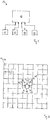
- Fig. 2 schematically illustrates a vehicle 16 in bird's eye view including a system 10' for generating maps representing the surrounding environment of the vehicle 16.
- the vehicle 16 is an exemplary embodiment according to the second aspect of the application.
- the system 10' is almost identical to the system 10 illustrated in Fig. 1 .
- the difference between the systems 10 and 10' is that the system 10' includes one radar sensor 11 of the first type and four radar sensors 12 of the second type.
- the radar sensor 11 is positioned on the front of the vehicle 16 and the four radar sensors 12 are positioned on each corner of the vehicle 16.
- the controller 15 installed in the vehicle 16 stores the information on the surrounding environment of the vehicle 16 received by the radar sensor 11 in a first map and the information on the surrounding environment of the vehicle 16 received by the radar sensors 12 in a second map as described above in connection with the system 10 shown in Fig. 1 . Further, the controller 15 may store information on the surrounding environment of the vehicle 16 in a fifth and sixth map as also explained above.
- Fig. 2 further shows an example of the maps stored by the controller 15.
- the map shown in Fig. 2 covers the immediate surrounding environment of the vehicle 16 and includes a plurality of cells M x,y arranged in an array (with the indices x and y denoting different cells). In the cells M x,y the detections made for a given polarization are stored.
- the position of an object 17 is shown in one of the cells M x,y . Further, the controller 15 has classified the detected object 17 as a tree. Since the controller 15 uses several maps with information extracted from radar signals with different polarizations and, in addition, the scattering properties of an object depend on the material the object is made of and also depend on the polarization of the radar signal, it is, for example, possible to determine from the maps stored by the controller 15 whether the object 17 is a tree or a pillar made of cement.
- the radar sensors 11 and 12 may have additional functions in the vehicle 16.
- the radar sensors 11 and 12 can be used for parking aid, adaptive cruise control, collision warning, autonomous emergency braking, lane departure warning, lane change assist and/or blind spot detection.
- Fig. 3 schematically illustrates a method 20 for generating maps representing a surrounding environment of a vehicle.
- the method 20 is an exemplary embodiment according to the third aspect of the application.
- the method 20 includes steps 21 and 22.
- step 21 radar signals with a first polarization are transmitted and received using a radar sensor of a first type, and radar signals with a second polarization are transmitted and received using a radar sensor of a second type.
- step 22 information on the surrounding environment of the vehicle extracted from the radar signals transmitted and received by the radar sensor of the first type are stored in a first map, and information on the surrounding environment of the vehicle extracted from the radar signals transmitted and received by the radar sensor of the second type are stored in a second map.
- the method 20 may include further steps and may comprise the embodiments disclosed above in connection with the system 10 and the vehicle 16.
Landscapes
- Engineering & Computer Science (AREA)
- Remote Sensing (AREA)
- Radar, Positioning & Navigation (AREA)
- Physics & Mathematics (AREA)
- Computer Networks & Wireless Communication (AREA)
- General Physics & Mathematics (AREA)
- Electromagnetism (AREA)
- Radar Systems Or Details Thereof (AREA)
- Traffic Control Systems (AREA)
Priority Applications (1)
| Application Number | Priority Date | Filing Date | Title |
|---|---|---|---|
| EP18167990.3A EP3557280B1 (de) | 2018-04-18 | 2018-04-18 | Vorrichtung und verfahren zur erzeugung von karten, die eine umgebung eines fahrzeugs darstellen |
Applications Claiming Priority (1)
| Application Number | Priority Date | Filing Date | Title |
|---|---|---|---|
| EP18167990.3A EP3557280B1 (de) | 2018-04-18 | 2018-04-18 | Vorrichtung und verfahren zur erzeugung von karten, die eine umgebung eines fahrzeugs darstellen |
Publications (2)
| Publication Number | Publication Date |
|---|---|
| EP3557280A1 true EP3557280A1 (de) | 2019-10-23 |
| EP3557280B1 EP3557280B1 (de) | 2023-05-03 |
Family
ID=62025710
Family Applications (1)
| Application Number | Title | Priority Date | Filing Date |
|---|---|---|---|
| EP18167990.3A Active EP3557280B1 (de) | 2018-04-18 | 2018-04-18 | Vorrichtung und verfahren zur erzeugung von karten, die eine umgebung eines fahrzeugs darstellen |
Country Status (1)
| Country | Link |
|---|---|
| EP (1) | EP3557280B1 (de) |
Cited By (1)
| Publication number | Priority date | Publication date | Assignee | Title |
|---|---|---|---|---|
| EP4137846A4 (de) * | 2020-05-01 | 2023-09-13 | Huawei Technologies Co., Ltd. | Verfahren zur erzeugung einer hochpräzisen karte, lokalisierungsverfahren und vorrichtung |
Citations (5)
| Publication number | Priority date | Publication date | Assignee | Title |
|---|---|---|---|---|
| US3757325A (en) * | 1970-12-18 | 1973-09-04 | Toyota Motor Co Ltd | Safety device for vehicle passengers |
| GB2351196A (en) * | 1999-04-01 | 2000-12-20 | Lear Automotive Dearborn Inc | Polarametric blind spot detector with steerable beam |
| GB2523092A (en) * | 2014-02-12 | 2015-08-19 | Jaguar Land Rover Ltd | A system for use in a vehicle |
| DE102015200939A1 (de) * | 2015-01-21 | 2016-07-21 | Robert Bosch Gmbh | Verfahren und System zur Detektion von Objekten in der Umgebung eines Fahrzeugs |
| DE102015003115A1 (de) * | 2015-03-11 | 2016-09-15 | Audi Ag | Verfahren zur Ermittlung einer Fahrbahnzustandsinformation und Kraftfahrzeug |
Family Cites Families (1)
| Publication number | Priority date | Publication date | Assignee | Title |
|---|---|---|---|---|
| US4490719A (en) * | 1981-11-27 | 1984-12-25 | United Technologies Corporation | Polarization controlled map matcher missile guidance system |
-
2018
- 2018-04-18 EP EP18167990.3A patent/EP3557280B1/de active Active
Patent Citations (5)
| Publication number | Priority date | Publication date | Assignee | Title |
|---|---|---|---|---|
| US3757325A (en) * | 1970-12-18 | 1973-09-04 | Toyota Motor Co Ltd | Safety device for vehicle passengers |
| GB2351196A (en) * | 1999-04-01 | 2000-12-20 | Lear Automotive Dearborn Inc | Polarametric blind spot detector with steerable beam |
| GB2523092A (en) * | 2014-02-12 | 2015-08-19 | Jaguar Land Rover Ltd | A system for use in a vehicle |
| DE102015200939A1 (de) * | 2015-01-21 | 2016-07-21 | Robert Bosch Gmbh | Verfahren und System zur Detektion von Objekten in der Umgebung eines Fahrzeugs |
| DE102015003115A1 (de) * | 2015-03-11 | 2016-09-15 | Audi Ag | Verfahren zur Ermittlung einer Fahrbahnzustandsinformation und Kraftfahrzeug |
Non-Patent Citations (3)
| Title |
|---|
| J. LOMBACHER; M. HAHN; J. DICKMANN; C. WOHLER: "Detection of arbitrarily rotated parked cars based on radar sensors", 16TH INTERNATIONAL RADAR SYMPOSIUM (IRS, 2015 |
| J. LOMBACHER; M. HAHN; J. DICKMANN; C. WOHLER: "Object classification in radar using ensemble methods", IEEE MTT-S INTERNATIONAL CONFERENCE ON MICROWAVES FOR INTELLIGENT MOBILITY (ICMIM, 2017 |
| X. XUE; L. DI; L. GUO; L. LIN: "2015 Fourth International Conference on Agro-Geoinformatics", 2015, article "An efficient classification method of fully polarimetric SAR image based on polarimetric features and spatial features" |
Cited By (1)
| Publication number | Priority date | Publication date | Assignee | Title |
|---|---|---|---|---|
| EP4137846A4 (de) * | 2020-05-01 | 2023-09-13 | Huawei Technologies Co., Ltd. | Verfahren zur erzeugung einer hochpräzisen karte, lokalisierungsverfahren und vorrichtung |
Also Published As
| Publication number | Publication date |
|---|---|
| EP3557280B1 (de) | 2023-05-03 |
Similar Documents
| Publication | Publication Date | Title |
|---|---|---|
| US11733353B2 (en) | Object detection using local (ground-aware) adaptive region proposals on point clouds | |
| Ilas | Electronic sensing technologies for autonomous ground vehicles: A review | |
| KR102860331B1 (ko) | 참조 데이터를 이용한 레이더 데이터 처리 장치 및 방법 | |
| US11340354B2 (en) | Methods to improve location/localization accuracy in autonomous machines with GNSS, LIDAR, RADAR, camera, and visual sensors | |
| US20200258392A1 (en) | Navigation techniques for autonomous and semi-autonomous vehicles | |
| Liu et al. | Cooperation of V2I/P2I communication and roadside radar perception for the safety of vulnerable road users | |
| US12117312B2 (en) | Systems and methods for vehicle mapping and localization using synthetic aperture radar | |
| US10871457B2 (en) | Determining material category based on the polarization of received signals | |
| EP0744630A2 (de) | Flughafen-Überwachungssystem und, System zur Warnung eines Eindringens auf eine Start-Landebahn | |
| EP3835823B1 (de) | Informationsverarbeitungsvorrichtung, informationsverarbeitungsverfahren, computerprogramm, informationsverarbeitungssystem und vorrichtung mit sich bewegendem körper | |
| CN115031981A (zh) | 一种车辆、传感器的仿真方法及装置 | |
| US20030061002A1 (en) | System and method for measuring short distances | |
| US10928507B2 (en) | Apparatus and method for improved radar beamforming | |
| US20150127249A1 (en) | Method and system for creating a current situation depiction | |
| CN108297880A (zh) | 分心驾驶员通知系统 | |
| US20190041522A1 (en) | Method and Apparatus Cross Segment Detection in a Lidar System | |
| WO2001011388A1 (en) | Methods and apparatus for stationary object detection | |
| US11036239B1 (en) | Object identification for autonomous road vehicles | |
| EP3557280B1 (de) | Vorrichtung und verfahren zur erzeugung von karten, die eine umgebung eines fahrzeugs darstellen | |
| WO2024081122A1 (en) | Object detection using radar sensors | |
| CN116136596A (zh) | 车辆雷达系统与通过车辆雷达系统检测移动目标的方法 | |
| US12117515B2 (en) | Fractalet radar processing | |
| CN114739381B (zh) | 一种机场车辆导航系统及方法 | |
| US20250102657A1 (en) | Information processing system, information processing apparatus, and information processing method | |
| Miccinesi et al. | Geo-Referenced Mapping through an Anti-Collision Radar Aboard an Unmanned Aerial System. Drones 2022, 6, 72 |
Legal Events
| Date | Code | Title | Description |
|---|---|---|---|
| PUAI | Public reference made under article 153(3) epc to a published international application that has entered the european phase |
Free format text: ORIGINAL CODE: 0009012 |
|
| STAA | Information on the status of an ep patent application or granted ep patent |
Free format text: STATUS: THE APPLICATION HAS BEEN PUBLISHED |
|
| AK | Designated contracting states |
Kind code of ref document: A1 Designated state(s): AL AT BE BG CH CY CZ DE DK EE ES FI FR GB GR HR HU IE IS IT LI LT LU LV MC MK MT NL NO PL PT RO RS SE SI SK SM TR |
|
| AX | Request for extension of the european patent |
Extension state: BA ME |
|
| STAA | Information on the status of an ep patent application or granted ep patent |
Free format text: STATUS: REQUEST FOR EXAMINATION WAS MADE |
|
| 17P | Request for examination filed |
Effective date: 20200406 |
|
| RBV | Designated contracting states (corrected) |
Designated state(s): AL AT BE BG CH CY CZ DE DK EE ES FI FR GB GR HR HU IE IS IT LI LT LU LV MC MK MT NL NO PL PT RO RS SE SI SK SM TR |
|
| STAA | Information on the status of an ep patent application or granted ep patent |
Free format text: STATUS: EXAMINATION IS IN PROGRESS |
|
| 17Q | First examination report despatched |
Effective date: 20211208 |
|
| GRAP | Despatch of communication of intention to grant a patent |
Free format text: ORIGINAL CODE: EPIDOSNIGR1 |
|
| STAA | Information on the status of an ep patent application or granted ep patent |
Free format text: STATUS: GRANT OF PATENT IS INTENDED |
|
| INTG | Intention to grant announced |
Effective date: 20230217 |
|
| GRAS | Grant fee paid |
Free format text: ORIGINAL CODE: EPIDOSNIGR3 |
|
| RAP3 | Party data changed (applicant data changed or rights of an application transferred) |
Owner name: APTIV TECHNOLOGIES LIMITED |
|
| GRAA | (expected) grant |
Free format text: ORIGINAL CODE: 0009210 |
|
| STAA | Information on the status of an ep patent application or granted ep patent |
Free format text: STATUS: THE PATENT HAS BEEN GRANTED |
|
| AK | Designated contracting states |
Kind code of ref document: B1 Designated state(s): AL AT BE BG CH CY CZ DE DK EE ES FI FR GB GR HR HU IE IS IT LI LT LU LV MC MK MT NL NO PL PT RO RS SE SI SK SM TR |
|
| REG | Reference to a national code |
Ref country code: GB Ref legal event code: FG4D |
|
| REG | Reference to a national code |
Ref country code: DE Ref legal event code: R096 Ref document number: 602018049108 Country of ref document: DE |
|
| REG | Reference to a national code |
Ref country code: AT Ref legal event code: REF Ref document number: 1565076 Country of ref document: AT Kind code of ref document: T Effective date: 20230515 Ref country code: CH Ref legal event code: EP |
|
| REG | Reference to a national code |
Ref country code: IE Ref legal event code: FG4D |
|
| P01 | Opt-out of the competence of the unified patent court (upc) registered |
Effective date: 20230626 |
|
| REG | Reference to a national code |
Ref country code: LT Ref legal event code: MG9D |
|
| REG | Reference to a national code |
Ref country code: NL Ref legal event code: MP Effective date: 20230503 |
|
| REG | Reference to a national code |
Ref country code: AT Ref legal event code: MK05 Ref document number: 1565076 Country of ref document: AT Kind code of ref document: T Effective date: 20230503 |
|
| PG25 | Lapsed in a contracting state [announced via postgrant information from national office to epo] |
Ref country code: SE Free format text: LAPSE BECAUSE OF FAILURE TO SUBMIT A TRANSLATION OF THE DESCRIPTION OR TO PAY THE FEE WITHIN THE PRESCRIBED TIME-LIMIT Effective date: 20230503 Ref country code: PT Free format text: LAPSE BECAUSE OF FAILURE TO SUBMIT A TRANSLATION OF THE DESCRIPTION OR TO PAY THE FEE WITHIN THE PRESCRIBED TIME-LIMIT Effective date: 20230904 Ref country code: NO Free format text: LAPSE BECAUSE OF FAILURE TO SUBMIT A TRANSLATION OF THE DESCRIPTION OR TO PAY THE FEE WITHIN THE PRESCRIBED TIME-LIMIT Effective date: 20230803 Ref country code: NL Free format text: LAPSE BECAUSE OF FAILURE TO SUBMIT A TRANSLATION OF THE DESCRIPTION OR TO PAY THE FEE WITHIN THE PRESCRIBED TIME-LIMIT Effective date: 20230503 Ref country code: ES Free format text: LAPSE BECAUSE OF FAILURE TO SUBMIT A TRANSLATION OF THE DESCRIPTION OR TO PAY THE FEE WITHIN THE PRESCRIBED TIME-LIMIT Effective date: 20230503 Ref country code: AT Free format text: LAPSE BECAUSE OF FAILURE TO SUBMIT A TRANSLATION OF THE DESCRIPTION OR TO PAY THE FEE WITHIN THE PRESCRIBED TIME-LIMIT Effective date: 20230503 |
|
| PG25 | Lapsed in a contracting state [announced via postgrant information from national office to epo] |
Ref country code: RS Free format text: LAPSE BECAUSE OF FAILURE TO SUBMIT A TRANSLATION OF THE DESCRIPTION OR TO PAY THE FEE WITHIN THE PRESCRIBED TIME-LIMIT Effective date: 20230503 Ref country code: PL Free format text: LAPSE BECAUSE OF FAILURE TO SUBMIT A TRANSLATION OF THE DESCRIPTION OR TO PAY THE FEE WITHIN THE PRESCRIBED TIME-LIMIT Effective date: 20230503 Ref country code: LV Free format text: LAPSE BECAUSE OF FAILURE TO SUBMIT A TRANSLATION OF THE DESCRIPTION OR TO PAY THE FEE WITHIN THE PRESCRIBED TIME-LIMIT Effective date: 20230503 Ref country code: LT Free format text: LAPSE BECAUSE OF FAILURE TO SUBMIT A TRANSLATION OF THE DESCRIPTION OR TO PAY THE FEE WITHIN THE PRESCRIBED TIME-LIMIT Effective date: 20230503 Ref country code: IS Free format text: LAPSE BECAUSE OF FAILURE TO SUBMIT A TRANSLATION OF THE DESCRIPTION OR TO PAY THE FEE WITHIN THE PRESCRIBED TIME-LIMIT Effective date: 20230903 Ref country code: HR Free format text: LAPSE BECAUSE OF FAILURE TO SUBMIT A TRANSLATION OF THE DESCRIPTION OR TO PAY THE FEE WITHIN THE PRESCRIBED TIME-LIMIT Effective date: 20230503 Ref country code: GR Free format text: LAPSE BECAUSE OF FAILURE TO SUBMIT A TRANSLATION OF THE DESCRIPTION OR TO PAY THE FEE WITHIN THE PRESCRIBED TIME-LIMIT Effective date: 20230804 |
|
| PG25 | Lapsed in a contracting state [announced via postgrant information from national office to epo] |
Ref country code: FI Free format text: LAPSE BECAUSE OF FAILURE TO SUBMIT A TRANSLATION OF THE DESCRIPTION OR TO PAY THE FEE WITHIN THE PRESCRIBED TIME-LIMIT Effective date: 20230503 |
|
| PG25 | Lapsed in a contracting state [announced via postgrant information from national office to epo] |
Ref country code: SK Free format text: LAPSE BECAUSE OF FAILURE TO SUBMIT A TRANSLATION OF THE DESCRIPTION OR TO PAY THE FEE WITHIN THE PRESCRIBED TIME-LIMIT Effective date: 20230503 |
|
| PG25 | Lapsed in a contracting state [announced via postgrant information from national office to epo] |
Ref country code: SM Free format text: LAPSE BECAUSE OF FAILURE TO SUBMIT A TRANSLATION OF THE DESCRIPTION OR TO PAY THE FEE WITHIN THE PRESCRIBED TIME-LIMIT Effective date: 20230503 Ref country code: SK Free format text: LAPSE BECAUSE OF FAILURE TO SUBMIT A TRANSLATION OF THE DESCRIPTION OR TO PAY THE FEE WITHIN THE PRESCRIBED TIME-LIMIT Effective date: 20230503 Ref country code: RO Free format text: LAPSE BECAUSE OF FAILURE TO SUBMIT A TRANSLATION OF THE DESCRIPTION OR TO PAY THE FEE WITHIN THE PRESCRIBED TIME-LIMIT Effective date: 20230503 Ref country code: EE Free format text: LAPSE BECAUSE OF FAILURE TO SUBMIT A TRANSLATION OF THE DESCRIPTION OR TO PAY THE FEE WITHIN THE PRESCRIBED TIME-LIMIT Effective date: 20230503 Ref country code: DK Free format text: LAPSE BECAUSE OF FAILURE TO SUBMIT A TRANSLATION OF THE DESCRIPTION OR TO PAY THE FEE WITHIN THE PRESCRIBED TIME-LIMIT Effective date: 20230503 Ref country code: CZ Free format text: LAPSE BECAUSE OF FAILURE TO SUBMIT A TRANSLATION OF THE DESCRIPTION OR TO PAY THE FEE WITHIN THE PRESCRIBED TIME-LIMIT Effective date: 20230503 |
|
| REG | Reference to a national code |
Ref country code: DE Ref legal event code: R097 Ref document number: 602018049108 Country of ref document: DE |
|
| PLBE | No opposition filed within time limit |
Free format text: ORIGINAL CODE: 0009261 |
|
| STAA | Information on the status of an ep patent application or granted ep patent |
Free format text: STATUS: NO OPPOSITION FILED WITHIN TIME LIMIT |
|
| 26N | No opposition filed |
Effective date: 20240206 |
|
| PG25 | Lapsed in a contracting state [announced via postgrant information from national office to epo] |
Ref country code: SI Free format text: LAPSE BECAUSE OF FAILURE TO SUBMIT A TRANSLATION OF THE DESCRIPTION OR TO PAY THE FEE WITHIN THE PRESCRIBED TIME-LIMIT Effective date: 20230503 |
|
| PG25 | Lapsed in a contracting state [announced via postgrant information from national office to epo] |
Ref country code: SI Free format text: LAPSE BECAUSE OF FAILURE TO SUBMIT A TRANSLATION OF THE DESCRIPTION OR TO PAY THE FEE WITHIN THE PRESCRIBED TIME-LIMIT Effective date: 20230503 Ref country code: IT Free format text: LAPSE BECAUSE OF FAILURE TO SUBMIT A TRANSLATION OF THE DESCRIPTION OR TO PAY THE FEE WITHIN THE PRESCRIBED TIME-LIMIT Effective date: 20230503 |
|
| PG25 | Lapsed in a contracting state [announced via postgrant information from national office to epo] |
Ref country code: BG Free format text: LAPSE BECAUSE OF FAILURE TO SUBMIT A TRANSLATION OF THE DESCRIPTION OR TO PAY THE FEE WITHIN THE PRESCRIBED TIME-LIMIT Effective date: 20230503 |
|
| PG25 | Lapsed in a contracting state [announced via postgrant information from national office to epo] |
Ref country code: MC Free format text: LAPSE BECAUSE OF FAILURE TO SUBMIT A TRANSLATION OF THE DESCRIPTION OR TO PAY THE FEE WITHIN THE PRESCRIBED TIME-LIMIT Effective date: 20230503 |
|
| PG25 | Lapsed in a contracting state [announced via postgrant information from national office to epo] |
Ref country code: MC Free format text: LAPSE BECAUSE OF FAILURE TO SUBMIT A TRANSLATION OF THE DESCRIPTION OR TO PAY THE FEE WITHIN THE PRESCRIBED TIME-LIMIT Effective date: 20230503 Ref country code: BG Free format text: LAPSE BECAUSE OF FAILURE TO SUBMIT A TRANSLATION OF THE DESCRIPTION OR TO PAY THE FEE WITHIN THE PRESCRIBED TIME-LIMIT Effective date: 20230503 |
|
| REG | Reference to a national code |
Ref country code: CH Ref legal event code: PL |
|
| PG25 | Lapsed in a contracting state [announced via postgrant information from national office to epo] |
Ref country code: LU Free format text: LAPSE BECAUSE OF NON-PAYMENT OF DUE FEES Effective date: 20240418 |
|
| REG | Reference to a national code |
Ref country code: BE Ref legal event code: MM Effective date: 20240430 |
|
| PG25 | Lapsed in a contracting state [announced via postgrant information from national office to epo] |
Ref country code: LU Free format text: LAPSE BECAUSE OF NON-PAYMENT OF DUE FEES Effective date: 20240418 |
|
| PG25 | Lapsed in a contracting state [announced via postgrant information from national office to epo] |
Ref country code: BE Free format text: LAPSE BECAUSE OF NON-PAYMENT OF DUE FEES Effective date: 20240430 |
|
| PG25 | Lapsed in a contracting state [announced via postgrant information from national office to epo] |
Ref country code: BE Free format text: LAPSE BECAUSE OF NON-PAYMENT OF DUE FEES Effective date: 20240430 Ref country code: CH Free format text: LAPSE BECAUSE OF NON-PAYMENT OF DUE FEES Effective date: 20240430 |
|
| PG25 | Lapsed in a contracting state [announced via postgrant information from national office to epo] |
Ref country code: IE Free format text: LAPSE BECAUSE OF NON-PAYMENT OF DUE FEES Effective date: 20240418 |
|
| REG | Reference to a national code |
Ref country code: DE Ref legal event code: R081 Ref document number: 602018049108 Country of ref document: DE Owner name: APTIV TECHNOLOGIES AG, CH Free format text: FORMER OWNER: APTIV TECHNOLOGIES LIMITED, ST. MICHAEL, BB |
|
| PGFP | Annual fee paid to national office [announced via postgrant information from national office to epo] |
Ref country code: DE Payment date: 20250313 Year of fee payment: 8 |
|
| PGFP | Annual fee paid to national office [announced via postgrant information from national office to epo] |
Ref country code: FR Payment date: 20250404 Year of fee payment: 8 |
|
| PG25 | Lapsed in a contracting state [announced via postgrant information from national office to epo] |
Ref country code: CY Free format text: LAPSE BECAUSE OF FAILURE TO SUBMIT A TRANSLATION OF THE DESCRIPTION OR TO PAY THE FEE WITHIN THE PRESCRIBED TIME-LIMIT; INVALID AB INITIO Effective date: 20180418 |
|
| PG25 | Lapsed in a contracting state [announced via postgrant information from national office to epo] |
Ref country code: HU Free format text: LAPSE BECAUSE OF FAILURE TO SUBMIT A TRANSLATION OF THE DESCRIPTION OR TO PAY THE FEE WITHIN THE PRESCRIBED TIME-LIMIT; INVALID AB INITIO Effective date: 20180418 |
|
| PGFP | Annual fee paid to national office [announced via postgrant information from national office to epo] |
Ref country code: GB Payment date: 20260305 Year of fee payment: 9 |