EP3557576A1 - Dispositif d'accentuation de son cible, dispositif d'apprentissage de paramètre d'estimation de bruit, procédé d'accentuation de son cible, procédé d'apprentissage de paramètre d'estimation de bruit et programme - Google Patents
Dispositif d'accentuation de son cible, dispositif d'apprentissage de paramètre d'estimation de bruit, procédé d'accentuation de son cible, procédé d'apprentissage de paramètre d'estimation de bruit et programme Download PDFInfo
- Publication number
- EP3557576A1 EP3557576A1 EP17881038.8A EP17881038A EP3557576A1 EP 3557576 A1 EP3557576 A1 EP 3557576A1 EP 17881038 A EP17881038 A EP 17881038A EP 3557576 A1 EP3557576 A1 EP 3557576A1
- Authority
- EP
- European Patent Office
- Prior art keywords
- microphone
- noise
- transfer function
- time frame
- probability distribution
- Prior art date
- Legal status (The legal status is an assumption and is not a legal conclusion. Google has not performed a legal analysis and makes no representation as to the accuracy of the status listed.)
- Granted
Links
Images



Classifications
-
- G—PHYSICS
- G10—MUSICAL INSTRUMENTS; ACOUSTICS
- G10L—SPEECH ANALYSIS TECHNIQUES OR SPEECH SYNTHESIS; SPEECH RECOGNITION; SPEECH OR VOICE PROCESSING TECHNIQUES; SPEECH OR AUDIO CODING OR DECODING
- G10L21/00—Speech or voice signal processing techniques to produce another audible or non-audible signal, e.g. visual or tactile, in order to modify its quality or its intelligibility
- G10L21/02—Speech enhancement, e.g. noise reduction or echo cancellation
- G10L21/0208—Noise filtering
- G10L21/0216—Noise filtering characterised by the method used for estimating noise
- G10L21/0232—Processing in the frequency domain
-
- G—PHYSICS
- G10—MUSICAL INSTRUMENTS; ACOUSTICS
- G10L—SPEECH ANALYSIS TECHNIQUES OR SPEECH SYNTHESIS; SPEECH RECOGNITION; SPEECH OR VOICE PROCESSING TECHNIQUES; SPEECH OR AUDIO CODING OR DECODING
- G10L21/00—Speech or voice signal processing techniques to produce another audible or non-audible signal, e.g. visual or tactile, in order to modify its quality or its intelligibility
- G10L21/02—Speech enhancement, e.g. noise reduction or echo cancellation
- G10L21/0208—Noise filtering
- G10L2021/02082—Noise filtering the noise being echo, reverberation of the speech
-
- G—PHYSICS
- G10—MUSICAL INSTRUMENTS; ACOUSTICS
- G10L—SPEECH ANALYSIS TECHNIQUES OR SPEECH SYNTHESIS; SPEECH RECOGNITION; SPEECH OR VOICE PROCESSING TECHNIQUES; SPEECH OR AUDIO CODING OR DECODING
- G10L21/00—Speech or voice signal processing techniques to produce another audible or non-audible signal, e.g. visual or tactile, in order to modify its quality or its intelligibility
- G10L21/02—Speech enhancement, e.g. noise reduction or echo cancellation
- G10L21/0208—Noise filtering
- G10L21/0216—Noise filtering characterised by the method used for estimating noise
- G10L2021/02161—Number of inputs available containing the signal or the noise to be suppressed
- G10L2021/02165—Two microphones, one receiving mainly the noise signal and the other one mainly the speech signal
-
- G—PHYSICS
- G10—MUSICAL INSTRUMENTS; ACOUSTICS
- G10L—SPEECH ANALYSIS TECHNIQUES OR SPEECH SYNTHESIS; SPEECH RECOGNITION; SPEECH OR VOICE PROCESSING TECHNIQUES; SPEECH OR AUDIO CODING OR DECODING
- G10L21/00—Speech or voice signal processing techniques to produce another audible or non-audible signal, e.g. visual or tactile, in order to modify its quality or its intelligibility
- G10L21/02—Speech enhancement, e.g. noise reduction or echo cancellation
- G10L21/0208—Noise filtering
- G10L21/0264—Noise filtering characterised by the type of parameter measurement, e.g. correlation techniques, zero crossing techniques or predictive techniques
Definitions
- the present invention relates to a technique that causes multiple microphones disposed at distant positions to cooperate with each other in a large space and enhances a target sound, and relates to a target sound enhancement device, a noise estimation parameter learning device, a target sound enhancement method, a noise estimation parameter learning method, and a program.
- Beamforming using a microphone array is a typical technique of suppressing noise arriving in a certain direction.
- a directional microphone such as a shotgun microphone or a parabolic microphone, is often used. In each technique, a sound arriving in a predetermined direction is enhanced, and sounds arriving in the other directions are suppressed.
- a situation is discussed where in a large space, such as a ballpark, a soccer ground, or a manufacturing factory, only a target sound is intended to be collected.
- Specific examples include collection of batting sounds and voices of umpires in a case of a ballpark, and collection of operation sounds of a certain manufacturing machine in a case of a manufacturing factory.
- noise sometimes arrives in the same direction as that of the target sound. Accordingly, the technique described above cannot only enhance the target sound.
- the "m-th microphone” also appears. Representation of the "m-th microphone” means a “freely selected microphone” with respect to the "first microphone”.
- the identification numbers are conceptual. There is no possibility that the position and characteristics of the microphone are identified by the identification number.
- representation of the "first microphone” does not mean that the microphone resides at a predetermined position, such as "behind the plate", for example.
- the "first microphone” means the predetermined microphone suitable for observation of the target sound. Consequently, when the position of the target sound moves, the position of the "first microphone” moves accordingly (more correctly, the identification number (index) assigned to the microphone is appropriately changed according to the movement of the target sound).
- an observed signal collected by beamforming or a directional microphone is assumed to be X (1) ⁇ , ⁇ ⁇ C ⁇ T .
- ⁇ 1,..., ⁇ and ⁇ ⁇ 1,..., T ⁇ are the indices of the frequency and time, respectively.
- H ⁇ (1) is the transfer characteristics from the target sound position to the microphone position.
- Formula (1) shows that the observed signal of the predetermined (first) microphone includes the target sound and noise.
- Time-frequency masking obtains a signal Y ⁇ , ⁇ including an enhanced target sound, using the time-frequency mask G ⁇ , ⁇ .
- the time-frequency masking based on the spectral subtraction method is a method that is used if
- the time-frequency mask is determined as follows using the estimated
- is a method of using a stationary component of
- N ⁇ , ⁇ ⁇ C ⁇ T includes non-stationary noise, such as drumming sounds in a sport field, and riveting sounds in a factory. Consequently,
- may be a method of directly observing noise through a microphone. It seems that in a case of a ballpark, a microphone is attached in the outfield stand, and cheers
- H ⁇ (m) is the transfer characteristics from an m-th microphone to a microphone serving as a main one.
- Non-patent Literature 1 S. Boll, "Suppression of acoustic noise in speech using spectral subtraction", IEEE Trans. ASLP, 1979 .
- the time length of reverberation (impulse response) that can be described as instantaneous mixture is 10 [ms].
- the reverberation time period in a sport field or a manufacturing factory is equal to or longer than this time length. Consequently, a simple instantaneous mixture model cannot be assumed.
- the outfield stand and the home plate are apart from each other by about 100 [m].
- cheers on the outfield stand arrives about 300 [ms] later.
- the sampling frequency is 48.0 [kHz] and the STFT shift width is 256
- a time frame difference P ⁇ 60 occurs. Owing to this time frame difference, a simple spectral subtraction method cannot be executed.
- the present invention has an object to provide a noise estimation parameter learning device according to which even in a large space causing a problem of the reverberation and the time frame difference, multiple microphones disposed at distant positions cooperate with each other, and a spectral subtraction method is executed, thereby allowing the target sound to be enhanced.
- a noise estimation parameter learning device is a device of learning noise estimation parameters used to estimate noise included in observed signals through a plurality of microphones, the noise estimation parameter learning device comprising: a modeling part; a likelihood function setting part; and a parameter update part.
- the modeling part models a probability distribution of observed signals of the predetermined microphone among the plurality of microphones, models a probability distribution of time frame differences caused according to a relative position difference between the predetermined microphone, the freely selected microphone and the noise source, and models a probability distribution of transfer function gains caused according to the relative position difference between the predetermined microphone, the freely selected microphone and the noise source.
- the likelihood function setting part sets a likelihood function pertaining to the time frame difference, and a likelihood function pertaining to the transfer function gain, based on the modeled probability distributions.
- the parameter update part alternately and repetitively updates a variable of the likelihood function pertaining to the time frame difference and a variable of the likelihood function pertaining to the transfer function gain, and outputs the converged time frame difference and the transfer function gain, as the noise estimation parameters.
- the noise estimation parameter learning device of the present invention even in a large space causing a problem of the reverberation and the time frame difference, multiple microphones disposed at distant positions cooperate with each other, and a spectral subtraction method is executed, thereby allowing the target sound to be enhanced.
- Embodiments of the present invention are hereinafter described in detail. Components having the same functions are assigned the same numerals, and redundant description is omitted.
- Embodiment 1 solves the two problems.
- Embodiment 1 provides a technique of estimating the time frame difference and reverberation so as to cause microphones disposed at positions far apart in a large space to cooperate with each other for sound source enhancement.
- the time frame difference and the reverberation (transfer function gain (Note ⁇ 1)) are described in a statistical model, and are estimated with respect to a likelihood maximization reference for an observed signal.
- the reverberation can be described as a transfer function in the frequency domain, and the gain thereof is called a transfer function gain.
- the noise estimation parameter learning device 1 in this embodiment includes a modeling part 11, a likelihood function setting part 12, and a parameter update part 13.
- the modeling part 11 includes an observed signal modeling part 111, a time frame difference modeling part 112, and a transfer function gain modeling part 113.
- the likelihood function setting part 12 includes an objective function setting part 121, a logarithmic part 122, and a term factorization part 123.
- the parameter update part 13 includes a transfer function gain update part 131, a time frame difference update part 132, and a convergence determination part 133.
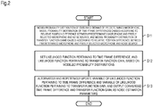
- the modeling part 11 models the probability distribution of observed signals of a predetermined microphone (first microphone) among the plurality of microphones, models the probability distribution of time frame differences caused according to the relative position difference between the predetermined microphone, a freely selected microphone (m-th microphone) and a noise source, and models the probability distribution of transfer function gains caused according to the relative position difference between the predetermined microphone, the freely selected microphone and the noise source (S11).
- the likelihood function setting part 12 sets a likelihood function pertaining to the time frame difference, and a likelihood function pertaining to the transfer function gain, based on the modeled probability distributions (S12).
- the parameter update part 13 alternately and repetitively updates a variable of the likelihood function pertaining to the time frame difference and a variable of the likelihood function pertaining to the transfer function gain, and outputs the time frame difference and the transfer function gain that have converged, as the noise estimation parameters (S13).
- ⁇ , ⁇ from observation through M microphones (M is an integer of two or more) is discussed.
- M is an integer of two or more.
- One or more of the microphones are assumed to be disposed (Note ⁇ 2) at positions sufficiently apart from a microphone serving as a main one.
- (Note ⁇ 2) a distance causing an arrival time difference equal to or more than the shift width of the short-time Fourier transform (STFT). That is, a distance causing the time frame difference in time-frequency analysis.
- STFT short-time Fourier transform
- the observed signal is a signal obtained by frequency-transforming an acoustic signal collected by the microphone, and the difference of two arrival times is equal to or more than the shift width of the frequency transformation, the arrival times being the arrival time of the noise from the noise source to the predetermined microphone and the arrival time of the noise from the noise source to the freely selected microphone.
- the identification number of the predetermined microphone disposed closest to S (1) ⁇ , ⁇ is assumed as one. Its observed signal X (1) ⁇ , ⁇ is assumed to be obtained by Formula (1). It is assumed that in a space there are M-1 point noise sources (e.g., public-address announcement) or a group of point noise sources (e.g., the cheering by supporters) S ⁇ , ⁇ 2 , ... , M
- Formula (7) shows that the observed signal of the freely selected (m-th) microphone includes noise. It is assumed that the noise N ⁇ , ⁇ reaching the first microphone consists only of S ⁇ , ⁇ 2 , ... , M
- P m ⁇ N + is the time frame difference in the time-frequency domain, the difference being caused according to the relative position difference between the first microphone, the m-th microphone and the noise source S(m) ⁇ , ⁇ .
- a (m) ⁇ ,k ⁇ R + is the transfer function gain, which is caused according to the relative position difference between the first microphone, the m-th microphone and the noise source S (m) ⁇ , ⁇ .
- the reverberation time period in a sport field or a manufacturing factory is equal to or longer than this time length. Consequently, a simple instantaneous mixture model cannot be assumed.
- the m-th sound source is assumed to arrive, with convolution of the amplitude spectrum of X (m) ⁇ , ⁇ with the transfer function gain a (m) ⁇ ,k in the time-frequency domain.
- Reference non-patent literature 1 describes this with complex spectral convolution. The present invention describes this with an amplitude spectrum for the sake of more simple description.
- ° is a Hadamard product.
- X ⁇ i X 1 , ⁇ i , X 2 , ⁇ i , ... , X ⁇ , ⁇ i T
- X ⁇ X ⁇ 2 , ... , X ⁇ M
- S (1) ⁇ , ⁇ is often sparse in the time frame direction (the target sound is not present almost over the time period).
- Data required for learning is input into the observed signal modeling part 111. Specifically, the observed signal X 1 , ... , ⁇ ,1 , ... , T 1 , ... , M is input.
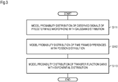
- the observed signal modeling part 111 models the probability distribution of the observed signal X (1) ⁇ of the predetermined microphone with a Gaussian distribution where N ⁇ is the average and a covariance matrix diag( ⁇ ) is adopted N N ⁇ , diag ⁇ 2 (Sill). [Formula 20] X ⁇ 1 ⁇ N X ⁇ 1
- ⁇ (diag( ⁇ )) -1 .
- the observed signal may be transformed from the time waveform into the complex spectrum using a method, such as STFT.
- STFT a method, such as STFT.
- X (m) ⁇ , ⁇ for M channels obtained by applying short-time Fourier transform to learning data is input.
- the microphone distance parameters include microphone distances ⁇ 2,..., M , and the minimum value and the maximum value of the sound source distance estimated from the microphone distances ⁇ 2,..., M ⁇ 2 , ... , M min , ⁇ 2 , ... , M max
- the signal processing parameters include the number of frames K, the sampling frequency f s , the STFT analysis width, and the shift length f shift .
- K 15 and therearound are recommended.
- the signal processing parameters may be set in conformity with the recording environment.
- the sampling frequency is 16.0 [kHz]
- the analysis width may be set to be about 512
- the shift length may be set to be about 256.
- the time frame difference modeling part 112 models the probability distribution of the time frame differences with a Poisson distribution (S112).
- the time frame difference modeling part 112 models the probability distribution of the time frame difference with a Poisson distribution having the average value D m (S112). [Formula 24] P m ⁇ Poisson P m
- Transfer function gain parameters are input into the transfer function gain modeling part 113.
- ⁇ is the value of ⁇ 0
- ⁇ is the attenuation weight according to frame passage
- ⁇ is a small coefficient for preventing division by zero.
- ⁇ 1.0 or therearound
- ⁇ 0.05
- the transfer function gain modeling part 113 models the probability distribution of the transfer function gains with an exponential distribution (S113).
- a (m) ⁇ ,k is a positive real number. In general, the value of the transfer function gain increases with increase in time k. To model this, the transfer function gain modeling part 113 models the probability distribution of the transfer function gains with an exponential distribution having the average value ⁇ k (S113). [Formula 28] a ⁇ , k m ⁇ Exponential a ⁇ , k m
- the probability distributions for the observed signal and each parameter can be defined.
- the parameters are estimated by maximizing the likelihood.
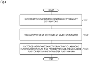
- the objective function setting part 121 sets the objective function as follows, on the basis of the modeled probability distribution (S121).
- L has a form of a product of probability value. Consequently, there is a possibility that underflow occurs during calculation. Accordingly, the fact that a logarithmic function is a monotonically increasing function is used, and the logarithms of both sides are taken. Specifically, the logarithmic part 122 takes logarithms of both sides of the objective function, and transforms Formulae (34) and (33) as follows (S 122).
- Formula (35) achieves maximization using the coordinate descent (CD) method.
- the term factorization part 123 factorizes the likelihood function (logarithmic objective function) to a term related to a (a term related to the transfer function gain), and a term related to P (a term related to the time frame difference) (S123).
- L a ln p X 1 , ... , T
- L P ln p X 1 , ... , T
- Formula (42) is optimization with the limitation. Accordingly, the optimization is achieved using the proximal gradient method.
- the transfer function gain update part 131 assigns a restriction that limits the transfer function gain to a nonnegative value, and repetitively updates the variable of the likelihood function pertaining to the transfer function gain by the proximal gradient method (S131).
- the transfer function gain update part 131 obtains the gradient vector of L a with respect to a by the following formula.
- ⁇ is an update step size.
- the number of repetitions of the gradient method, i.e., Formulae (47) and (48), is about 30 in the case of the batch learning, and about one in the case of the online learning.
- the gradient of Formula (44) may be adjusted using an inertial term (Reference non-patent literature 2) or the like.
- Formula (43) is combinatorial optimization of discrete variables. Accordingly, update is performed by grid searching. Specifically, the time frame difference update part 132 defines the possible maximum value and minimum value of P m for every m, evaluates, for every combination of the minimum and maximum for P m , the likelihood function related to the time frame difference L P and updates P m with the combination of maximizing the function (S 132). For practical use, the minimum value ⁇ 2 , ... , M min and the maximum value ⁇ 2 , ... , M max estimated from each microphone distance ⁇ 2,..., M are input, and the possible maximum value and minimum value for P m may be calculated therefrom.
- the above update can be executed by a batch process of preliminarily estimating ⁇ using the learning data.
- the observed signal may be buffered for a certain time period, and estimation of ⁇ may then be executed using the buffer.
- noise may be estimated by Formula (8), and the target sound may be enhanced by Formulae (4) and (5).
- the convergence determination part 133 determines whether the algorithm has converged or not (S133).
- the determination method may be, for example, the sum of absolute values of the update amount of a (m) ⁇ ,k , whether the learning times are equal to or more than a predetermined number (e.g., 1000 times) or the like.
- a predetermined number e.g. 1000 times
- the learning may be finished after a certain number of repetitions of learning (e.g., 1 to 5).
- the convergence determination part 133 outputs the converged time frame difference and transfer function gain as noise estimation parameter ⁇ .
- the noise estimation parameter learning device 1 of this embodiment even in a large space causing a problem of the reverberation and the time frame difference, multiple microphones disposed at distant positions cooperate with each other, and the spectral subtraction method is executed, thereby allowing the target sound to be enhanced.
- a target sound enhancement device that is a device of enhancing the target sound on the basis of the noise estimation parameter ⁇ obtained in Embodiment 1 is described.
- the configuration of the target sound enhancement device 2 of this embodiment is described.
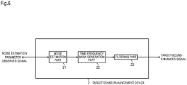
- the target sound enhancement device 2 of this embodiment includes a noise estimation part 21, a time-frequency mask generation part 22, and a filtering part 23.
- Fig. 7 the operation of the target sound enhancement device 2 of this embodiment is described.
- Data required for enhancement is input into the noise estimation part 21.
- the observed signal X 1 , ... , ⁇ , ⁇ 1 , ... , M and the noise estimation parameter ⁇ are input.
- the noise estimation part 21 estimates noise included in the observed signals through M (multiple) microphones on the basis of the observed signals and the noise estimation parameter ⁇ by Formula (8) (S21).
- the noise estimation parameter ⁇ and Formula (8) may be construed as a parameter and formula where an observed signal from the predetermined microphone among the plurality of microphones, the time frame difference caused according to the relative position difference between the predetermined microphone, the freely selected microphone that is among the plurality of microphones and is different from the predetermined microphone and the noise source, and the transfer function gain caused according to the relative position difference between the predetermined microphone, the freely selected microphone and the noise source, are associated with each other.
- the target sound enhancement device 2 may have a configuration independent of the noise estimation parameter learning device 1. That is, independent of the noise estimation parameter ⁇ , according to Formula (8), the noise estimation part 21 may associate the observed signal from the predetermined microphone among the plurality of microphones, the time frame difference caused according to the relative position difference between the predetermined microphone, the freely selected microphone that is among the plurality of microphones and is different from the predetermined microphone and the noise source, and the transfer function gain caused according to the relative position difference between the predetermined microphone, the freely selected microphone and the noise source, with each other, and estimate noise included in observed signals through a plurality of the predetermined microphones.
- the time-frequency mask generation part 22 generates the time-frequency mask G ⁇ , ⁇ based on the spectral subtraction method by Formula (4), on the basis of the observed signal
- the time-frequency mask generation part 22 may be called a filter generation part.
- the filter generation part generates a filter, based at least on the estimated noise by Formula (4) or the like.
- the filtering part 23 filters the observed signal
- acoustic signal complex spectrum Y ⁇ , ⁇
- S23 inverse short-time Fourier transform
- ISTFT inverse short-time Fourier transform
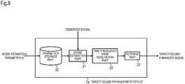
- Embodiment 2 has the configuration where the noise estimation part 21 receives (accepts) the noise estimation parameter ⁇ from another device (noise estimation parameter learning device 1) as required. It is a matter of course that another mode of the target sound enhancement device can be considered. For example, as a target sound enhancement device 2a of Modification 1 shown in Fig. 8 , the noise estimation parameter ⁇ may be preliminarily received from the other device (noise estimation parameter learning device 1), and preliminarily stored in a parameter storage part 20.
- the parameter storage part 20 preliminarily stores and holds the time frame difference and transfer function gain having been converged by alternately and repetitively updating the variables of the two likelihood functions set based on the three probability distributions described above, as the noise estimation parameter ⁇ .
- the target sound enhancement devices 2 and 2a of this embodiment and this modification even in the large space causing the problem of the reverberation and the time frame difference, the multiple microphones disposed at distant positions cooperate with each other, and the spectral subtraction method is executed, thereby allowing the target sound to be enhanced.
- the device of the present invention includes, as a single hardware entity, for example: an input part to which a keyboard and the like can be connected; an output part to which a liquid crystal display and the like can be connected; a communication part to which a communication device (e.g., a communication cable) communicable with the outside of the hardware entity can be connected; a CPU (Central Processing Unit, which may include a cache memory and a register); a RAM and a ROM, which are memories; an external storage device that is a hard disk; and a bus that connects these input part, output part, communication part, CPU, RAM, ROM and external storing device to each other in a manner allowing data to be exchanged therebetween.
- the hardware entity may be provided with a device (drive) capable of reading and writing from and to a recording medium, such as CD-ROM, as required.
- a physical entity including such a hardware resource may be a general-purpose computer or the like.
- the external storage device of the hardware entity stores programs required to achieve the functions described above and data required for the processes of the programs (not limited to the external storage device; for example, programs may be stored in a ROM, which is a storage device dedicated for reading, for example). Data and the like obtained by the processes of the programs are appropriately stored in the RAM or the external storage device.
- each program stored in the external storage device or a ROM etc.
- data required for the process of each program are read into the memory, as required, and are appropriately subjected to analysis, execution and processing by the CPU.
- the CPU achieves predetermined functions (each component represented as ... part, ... portion, etc. described above).
- the present invention is not limited to the embodiments described above, and can be appropriately changed in a range without departing from the spirit of the present invention.
- the processes described in the above embodiments may be executed in a time series manner according to the described order. Alternatively, the processes may be executed in parallel or separately, according to the processing capability of the device that executes the processes, or as required.
- the processing functions of the hardware entity (the device of the present invention) described in the embodiments are achieved by a computer
- the processing details of the functions to be held by the hardware entity are described in a program.
- the program is executed by the computer, thereby achieving the processing functions in the hardware entity on the computer.
- the program that describes the processing details can be recorded in a computer-readable recording medium.
- the computer-readable recording medium may be, for example, any of a magnetic recording device, an optical disk, a magneto-optical recording medium, a semiconductor memory and the like.
- a hard disk device, a flexible disk, a magnetic tape and the like may be used as the magnetic recording device.
- a DVD (Digital Versatile Disc), a DVD-RAM (Random Access Memory), a CD-ROM (Compact Disc Read Only Memory), CD-R (Recordable)/RW (Rewritable) and the like may be used as the optical disk.
- An MO Magneticto-Optical disc
- An EEP-ROM Electrically Erasable and Programmable-Read Only Memory
- the program may be distributed by selling, assigning, lending and the like of portable recording media, such as a DVD and a CD-ROM, which record the program.
- portable recording media such as a DVD and a CD-ROM
- a configuration may be adopted that distributes the program by storing the program in the storage device of the server computer and then transferring the program from the server computer to another computer via a network.
- the computer that executes such a program temporarily stores, in the own storage device, the program stored in the portable recording medium or the program transferred from the server computer. During execution of the process, the computer reads the program stored in the own recording medium, and executes the process according to the read program. Alternatively, according to another execution mode of the program, the computer may directly read the program from the portable recording medium, and execute the process according to the program. Further alternatively, every time the program is transferred to this computer from the server computer, the process according to the received program may be sequentially executed.
- a configuration may be adopted that does not transfer the program to this computer from the server computer but executes the processes described above by what is called an ASP (Application Service Provider) service that achieves the processing functions only through execution instructions and result acquisition.
- ASP Application Service Provider
- the program of this mode includes information that is to be provided for the processes by a computer and is equivalent to the program (data and the like having characteristics that are not direct instructions to the computer but define the processes of the computer).
- the hardware entity can be configured by executing a predetermined program on the computer.
- at least one or some of the processing details may be achieved by hardware.
Landscapes
- Engineering & Computer Science (AREA)
- Computational Linguistics (AREA)
- Quality & Reliability (AREA)
- Signal Processing (AREA)
- Health & Medical Sciences (AREA)
- Audiology, Speech & Language Pathology (AREA)
- Human Computer Interaction (AREA)
- Physics & Mathematics (AREA)
- Acoustics & Sound (AREA)
- Multimedia (AREA)
- Circuit For Audible Band Transducer (AREA)
- Measurement Of Mechanical Vibrations Or Ultrasonic Waves (AREA)
- Soundproofing, Sound Blocking, And Sound Damping (AREA)
Applications Claiming Priority (2)
| Application Number | Priority Date | Filing Date | Title |
|---|---|---|---|
| JP2016244169 | 2016-12-16 | ||
| PCT/JP2017/032866 WO2018110008A1 (fr) | 2016-12-16 | 2017-09-12 | Dispositif d'accentuation de son cible, dispositif d'apprentissage de paramètre d'estimation de bruit, procédé d'accentuation de son cible, procédé d'apprentissage de paramètre d'estimation de bruit et programme |
Publications (3)
| Publication Number | Publication Date |
|---|---|
| EP3557576A1 true EP3557576A1 (fr) | 2019-10-23 |
| EP3557576A4 EP3557576A4 (fr) | 2020-08-12 |
| EP3557576B1 EP3557576B1 (fr) | 2022-12-07 |
Family
ID=62558463
Family Applications (1)
| Application Number | Title | Priority Date | Filing Date |
|---|---|---|---|
| EP17881038.8A Active EP3557576B1 (fr) | 2016-12-16 | 2017-09-12 | Dispositif d'accentuation de son cible, dispositif d'apprentissage de paramètre d'estimation de bruit, procédé d'accentuation de son cible, procédé d'apprentissage de paramètre d'estimation de bruit et programme |
Country Status (6)
| Country | Link |
|---|---|
| US (1) | US11322169B2 (fr) |
| EP (1) | EP3557576B1 (fr) |
| JP (1) | JP6732944B2 (fr) |
| CN (1) | CN110036441B (fr) |
| ES (1) | ES2937232T3 (fr) |
| WO (1) | WO2018110008A1 (fr) |
Families Citing this family (2)
| Publication number | Priority date | Publication date | Assignee | Title |
|---|---|---|---|---|
| WO2020207580A1 (fr) * | 2019-04-10 | 2020-10-15 | Huawei Technologies Co., Ltd. | Appareil de traitement audio et procédé de localisation d'une source audio |
| WO2021205494A1 (fr) * | 2020-04-06 | 2021-10-14 | 日本電信電話株式会社 | Dispositif de traitement de signal, procédé de traitement de signal, et programme |
Family Cites Families (14)
| Publication number | Priority date | Publication date | Assignee | Title |
|---|---|---|---|---|
| EP1600791B1 (fr) * | 2004-05-26 | 2009-04-01 | Honda Research Institute Europe GmbH | Localisation d'une source acoustique basée sur des signaux binauraux |
| EP1640971B1 (fr) * | 2004-09-23 | 2008-08-20 | Harman Becker Automotive Systems GmbH | Traitement adaptatif d'un signal de parole multicanaux avec suppression du bruit |
| EP1993320B1 (fr) * | 2006-03-03 | 2015-01-07 | Nippon Telegraph And Telephone Corporation | Dispositif, procede et programme d'elimination de la reverberation et support d'enregistrement |
| US20080152167A1 (en) * | 2006-12-22 | 2008-06-26 | Step Communications Corporation | Near-field vector signal enhancement |
| US7983428B2 (en) * | 2007-05-09 | 2011-07-19 | Motorola Mobility, Inc. | Noise reduction on wireless headset input via dual channel calibration within mobile phone |
| US8174932B2 (en) * | 2009-06-11 | 2012-05-08 | Hewlett-Packard Development Company, L.P. | Multimodal object localization |
| JP5143802B2 (ja) * | 2009-09-01 | 2013-02-13 | 日本電信電話株式会社 | 雑音除去装置、遠近判定装置と、各装置の方法と、装置プログラム |
| JP5337072B2 (ja) * | 2010-02-12 | 2013-11-06 | 日本電信電話株式会社 | モデル推定装置、音源分離装置、それらの方法及びプログラム |
| FR2976111B1 (fr) * | 2011-06-01 | 2013-07-05 | Parrot | Equipement audio comprenant des moyens de debruitage d'un signal de parole par filtrage a delai fractionnaire, notamment pour un systeme de telephonie "mains libres" |
| US9338551B2 (en) * | 2013-03-15 | 2016-05-10 | Broadcom Corporation | Multi-microphone source tracking and noise suppression |
| JP6193823B2 (ja) * | 2014-08-19 | 2017-09-06 | 日本電信電話株式会社 | 音源数推定装置、音源数推定方法および音源数推定プログラム |
| US10127919B2 (en) * | 2014-11-12 | 2018-11-13 | Cirrus Logic, Inc. | Determining noise and sound power level differences between primary and reference channels |
| CN105225672B (zh) * | 2015-08-21 | 2019-02-22 | 胡旻波 | 融合基频信息的双麦克风定向噪音抑制的系统及方法 |
| CN105590630B (zh) * | 2016-02-18 | 2019-06-07 | 深圳永顺智信息科技有限公司 | 基于指定带宽的定向噪音抑制方法 |
-
2017
- 2017-09-12 EP EP17881038.8A patent/EP3557576B1/fr active Active
- 2017-09-12 US US16/463,958 patent/US11322169B2/en active Active
- 2017-09-12 WO PCT/JP2017/032866 patent/WO2018110008A1/fr not_active Ceased
- 2017-09-12 JP JP2018556185A patent/JP6732944B2/ja active Active
- 2017-09-12 CN CN201780075048.0A patent/CN110036441B/zh active Active
- 2017-09-12 ES ES17881038T patent/ES2937232T3/es active Active
Also Published As
| Publication number | Publication date |
|---|---|
| EP3557576A4 (fr) | 2020-08-12 |
| CN110036441A (zh) | 2019-07-19 |
| CN110036441B (zh) | 2023-02-17 |
| EP3557576B1 (fr) | 2022-12-07 |
| US11322169B2 (en) | 2022-05-03 |
| JPWO2018110008A1 (ja) | 2019-10-24 |
| US20200388298A1 (en) | 2020-12-10 |
| ES2937232T3 (es) | 2023-03-27 |
| JP6732944B2 (ja) | 2020-07-29 |
| WO2018110008A1 (fr) | 2018-06-21 |
Similar Documents
| Publication | Publication Date | Title |
|---|---|---|
| US7295972B2 (en) | Method and apparatus for blind source separation using two sensors | |
| JP5124014B2 (ja) | 信号強調装置、その方法、プログラム及び記録媒体 | |
| JP6723120B2 (ja) | 音響処理装置および音響処理方法 | |
| JP4977062B2 (ja) | 残響除去装置とその方法と、そのプログラムと記録媒体 | |
| CN113470685A (zh) | 语音增强模型的训练方法和装置及语音增强方法和装置 | |
| JP6538624B2 (ja) | 信号処理装置、信号処理方法および信号処理プログラム | |
| JP2019090930A (ja) | 音源強調装置、音源強調学習装置、音源強調方法、プログラム | |
| JP5881454B2 (ja) | 音源ごとに信号のスペクトル形状特徴量を推定する装置、方法、目的信号のスペクトル特徴量を推定する装置、方法、プログラム | |
| EP3557576B1 (fr) | Dispositif d'accentuation de son cible, dispositif d'apprentissage de paramètre d'estimation de bruit, procédé d'accentuation de son cible, procédé d'apprentissage de paramètre d'estimation de bruit et programme | |
| Doulaty et al. | Automatic optimization of data perturbation distributions for multi-style training in speech recognition | |
| JP6973254B2 (ja) | 信号分析装置、信号分析方法および信号分析プログラム | |
| JP2006243290A (ja) | 外乱成分抑圧装置、コンピュータプログラム、及び音声認識システム | |
| JP5726790B2 (ja) | 音源分離装置、音源分離方法、およびプログラム | |
| US11297418B2 (en) | Acoustic signal separation apparatus, learning apparatus, method, and program thereof | |
| Yadav et al. | Joint dereverberation and beamforming with blind estimation of the shape parameter of the desired source prior | |
| JP6734237B2 (ja) | 目的音源推定装置、目的音源推定方法及び目的音源推定プログラム | |
| KR101647059B1 (ko) | 독립 벡터 분석 및 모델 기반 특징 향상을 이용한 강인한 음성 인식 방법 | |
| JP5498452B2 (ja) | 背景音抑圧装置、背景音抑圧方法、およびプログラム | |
| US20230296767A1 (en) | Acoustic-environment mismatch and proximity detection with a novel set of acoustic relative features and adaptive filtering | |
| JP6059112B2 (ja) | 音源分離装置とその方法とプログラム | |
| WO2019208137A1 (fr) | Dispositif de séparation de sources sonores, procédé pour sa mise en œuvre et programme | |
| JP2018191255A (ja) | 収音装置、その方法、及びプログラム | |
| Koizumi et al. | Distant Noise Reduction Based on Multi-delay Noise Model Using Distributed Microphone Array | |
| JP5683446B2 (ja) | スペクトル歪みパラメータ推定値補正装置とその方法とプログラム | |
| JP5530988B2 (ja) | 背景音抑圧装置、背景音抑圧方法、およびプログラム |
Legal Events
| Date | Code | Title | Description |
|---|---|---|---|
| STAA | Information on the status of an ep patent application or granted ep patent |
Free format text: STATUS: THE INTERNATIONAL PUBLICATION HAS BEEN MADE |
|
| PUAI | Public reference made under article 153(3) epc to a published international application that has entered the european phase |
Free format text: ORIGINAL CODE: 0009012 |
|
| STAA | Information on the status of an ep patent application or granted ep patent |
Free format text: STATUS: REQUEST FOR EXAMINATION WAS MADE |
|
| 17P | Request for examination filed |
Effective date: 20190716 |
|
| AK | Designated contracting states |
Kind code of ref document: A1 Designated state(s): AL AT BE BG CH CY CZ DE DK EE ES FI FR GB GR HR HU IE IS IT LI LT LU LV MC MK MT NL NO PL PT RO RS SE SI SK SM TR |
|
| AX | Request for extension of the european patent |
Extension state: BA ME |
|
| DAV | Request for validation of the european patent (deleted) | ||
| DAX | Request for extension of the european patent (deleted) | ||
| A4 | Supplementary search report drawn up and despatched |
Effective date: 20200715 |
|
| RIC1 | Information provided on ipc code assigned before grant |
Ipc: G10L 21/0208 20130101ALI20200709BHEP Ipc: G10L 21/0232 20130101ALI20200709BHEP Ipc: G10L 21/0264 20130101AFI20200709BHEP |
|
| STAA | Information on the status of an ep patent application or granted ep patent |
Free format text: STATUS: EXAMINATION IS IN PROGRESS |
|
| 17Q | First examination report despatched |
Effective date: 20210319 |
|
| REG | Reference to a national code |
Ref country code: DE Ref legal event code: R079 Ref document number: 602017064493 Country of ref document: DE Free format text: PREVIOUS MAIN CLASS: G10L0021026400 Ipc: G10L0021021600 |
|
| GRAJ | Information related to disapproval of communication of intention to grant by the applicant or resumption of examination proceedings by the epo deleted |
Free format text: ORIGINAL CODE: EPIDOSDIGR1 |
|
| GRAP | Despatch of communication of intention to grant a patent |
Free format text: ORIGINAL CODE: EPIDOSNIGR1 |
|
| GRAP | Despatch of communication of intention to grant a patent |
Free format text: ORIGINAL CODE: EPIDOSNIGR1 |
|
| STAA | Information on the status of an ep patent application or granted ep patent |
Free format text: STATUS: GRANT OF PATENT IS INTENDED |
|
| RIC1 | Information provided on ipc code assigned before grant |
Ipc: G10L 21/0232 20130101ALI20220719BHEP Ipc: G10L 21/0264 20130101ALI20220719BHEP Ipc: G10L 21/0208 20130101ALI20220719BHEP Ipc: G10L 21/0216 20130101AFI20220719BHEP |
|
| INTG | Intention to grant announced |
Effective date: 20220802 |
|
| GRAS | Grant fee paid |
Free format text: ORIGINAL CODE: EPIDOSNIGR3 |
|
| GRAA | (expected) grant |
Free format text: ORIGINAL CODE: 0009210 |
|
| STAA | Information on the status of an ep patent application or granted ep patent |
Free format text: STATUS: THE PATENT HAS BEEN GRANTED |
|
| AK | Designated contracting states |
Kind code of ref document: B1 Designated state(s): AL AT BE BG CH CY CZ DE DK EE ES FI FR GB GR HR HU IE IS IT LI LT LU LV MC MK MT NL NO PL PT RO RS SE SI SK SM TR |
|
| REG | Reference to a national code |
Ref country code: GB Ref legal event code: FG4D |
|
| REG | Reference to a national code |
Ref country code: CH Ref legal event code: EP Ref country code: AT Ref legal event code: REF Ref document number: 1536782 Country of ref document: AT Kind code of ref document: T Effective date: 20221215 |
|
| REG | Reference to a national code |
Ref country code: DE Ref legal event code: R096 Ref document number: 602017064493 Country of ref document: DE |
|
| REG | Reference to a national code |
Ref country code: IE Ref legal event code: FG4D |
|
| REG | Reference to a national code |
Ref country code: LT Ref legal event code: MG9D Ref country code: ES Ref legal event code: FG2A Ref document number: 2937232 Country of ref document: ES Kind code of ref document: T3 Effective date: 20230327 |
|
| REG | Reference to a national code |
Ref country code: NL Ref legal event code: MP Effective date: 20221207 |
|
| PG25 | Lapsed in a contracting state [announced via postgrant information from national office to epo] |
Ref country code: SE Free format text: LAPSE BECAUSE OF FAILURE TO SUBMIT A TRANSLATION OF THE DESCRIPTION OR TO PAY THE FEE WITHIN THE PRESCRIBED TIME-LIMIT Effective date: 20221207 Ref country code: NO Free format text: LAPSE BECAUSE OF FAILURE TO SUBMIT A TRANSLATION OF THE DESCRIPTION OR TO PAY THE FEE WITHIN THE PRESCRIBED TIME-LIMIT Effective date: 20230307 Ref country code: LT Free format text: LAPSE BECAUSE OF FAILURE TO SUBMIT A TRANSLATION OF THE DESCRIPTION OR TO PAY THE FEE WITHIN THE PRESCRIBED TIME-LIMIT Effective date: 20221207 Ref country code: FI Free format text: LAPSE BECAUSE OF FAILURE TO SUBMIT A TRANSLATION OF THE DESCRIPTION OR TO PAY THE FEE WITHIN THE PRESCRIBED TIME-LIMIT Effective date: 20221207 |
|
| REG | Reference to a national code |
Ref country code: AT Ref legal event code: MK05 Ref document number: 1536782 Country of ref document: AT Kind code of ref document: T Effective date: 20221207 |
|
| PG25 | Lapsed in a contracting state [announced via postgrant information from national office to epo] |
Ref country code: RS Free format text: LAPSE BECAUSE OF FAILURE TO SUBMIT A TRANSLATION OF THE DESCRIPTION OR TO PAY THE FEE WITHIN THE PRESCRIBED TIME-LIMIT Effective date: 20221207 Ref country code: PL Free format text: LAPSE BECAUSE OF FAILURE TO SUBMIT A TRANSLATION OF THE DESCRIPTION OR TO PAY THE FEE WITHIN THE PRESCRIBED TIME-LIMIT Effective date: 20221207 Ref country code: LV Free format text: LAPSE BECAUSE OF FAILURE TO SUBMIT A TRANSLATION OF THE DESCRIPTION OR TO PAY THE FEE WITHIN THE PRESCRIBED TIME-LIMIT Effective date: 20221207 Ref country code: HR Free format text: LAPSE BECAUSE OF FAILURE TO SUBMIT A TRANSLATION OF THE DESCRIPTION OR TO PAY THE FEE WITHIN THE PRESCRIBED TIME-LIMIT Effective date: 20221207 Ref country code: GR Free format text: LAPSE BECAUSE OF FAILURE TO SUBMIT A TRANSLATION OF THE DESCRIPTION OR TO PAY THE FEE WITHIN THE PRESCRIBED TIME-LIMIT Effective date: 20230308 |
|
| PG25 | Lapsed in a contracting state [announced via postgrant information from national office to epo] |
Ref country code: NL Free format text: LAPSE BECAUSE OF FAILURE TO SUBMIT A TRANSLATION OF THE DESCRIPTION OR TO PAY THE FEE WITHIN THE PRESCRIBED TIME-LIMIT Effective date: 20221207 |
|
| PG25 | Lapsed in a contracting state [announced via postgrant information from national office to epo] |
Ref country code: SM Free format text: LAPSE BECAUSE OF FAILURE TO SUBMIT A TRANSLATION OF THE DESCRIPTION OR TO PAY THE FEE WITHIN THE PRESCRIBED TIME-LIMIT Effective date: 20221207 Ref country code: RO Free format text: LAPSE BECAUSE OF FAILURE TO SUBMIT A TRANSLATION OF THE DESCRIPTION OR TO PAY THE FEE WITHIN THE PRESCRIBED TIME-LIMIT Effective date: 20221207 Ref country code: PT Free format text: LAPSE BECAUSE OF FAILURE TO SUBMIT A TRANSLATION OF THE DESCRIPTION OR TO PAY THE FEE WITHIN THE PRESCRIBED TIME-LIMIT Effective date: 20230410 Ref country code: EE Free format text: LAPSE BECAUSE OF FAILURE TO SUBMIT A TRANSLATION OF THE DESCRIPTION OR TO PAY THE FEE WITHIN THE PRESCRIBED TIME-LIMIT Effective date: 20221207 Ref country code: CZ Free format text: LAPSE BECAUSE OF FAILURE TO SUBMIT A TRANSLATION OF THE DESCRIPTION OR TO PAY THE FEE WITHIN THE PRESCRIBED TIME-LIMIT Effective date: 20221207 Ref country code: AT Free format text: LAPSE BECAUSE OF FAILURE TO SUBMIT A TRANSLATION OF THE DESCRIPTION OR TO PAY THE FEE WITHIN THE PRESCRIBED TIME-LIMIT Effective date: 20221207 |
|
| PG25 | Lapsed in a contracting state [announced via postgrant information from national office to epo] |
Ref country code: SK Free format text: LAPSE BECAUSE OF FAILURE TO SUBMIT A TRANSLATION OF THE DESCRIPTION OR TO PAY THE FEE WITHIN THE PRESCRIBED TIME-LIMIT Effective date: 20221207 Ref country code: IS Free format text: LAPSE BECAUSE OF FAILURE TO SUBMIT A TRANSLATION OF THE DESCRIPTION OR TO PAY THE FEE WITHIN THE PRESCRIBED TIME-LIMIT Effective date: 20230407 Ref country code: AL Free format text: LAPSE BECAUSE OF FAILURE TO SUBMIT A TRANSLATION OF THE DESCRIPTION OR TO PAY THE FEE WITHIN THE PRESCRIBED TIME-LIMIT Effective date: 20221207 |
|
| REG | Reference to a national code |
Ref country code: DE Ref legal event code: R097 Ref document number: 602017064493 Country of ref document: DE |
|
| PLBE | No opposition filed within time limit |
Free format text: ORIGINAL CODE: 0009261 |
|
| STAA | Information on the status of an ep patent application or granted ep patent |
Free format text: STATUS: NO OPPOSITION FILED WITHIN TIME LIMIT |
|
| PG25 | Lapsed in a contracting state [announced via postgrant information from national office to epo] |
Ref country code: DK Free format text: LAPSE BECAUSE OF FAILURE TO SUBMIT A TRANSLATION OF THE DESCRIPTION OR TO PAY THE FEE WITHIN THE PRESCRIBED TIME-LIMIT Effective date: 20221207 |
|
| 26N | No opposition filed |
Effective date: 20230908 |
|
| PG25 | Lapsed in a contracting state [announced via postgrant information from national office to epo] |
Ref country code: SI Free format text: LAPSE BECAUSE OF FAILURE TO SUBMIT A TRANSLATION OF THE DESCRIPTION OR TO PAY THE FEE WITHIN THE PRESCRIBED TIME-LIMIT Effective date: 20221207 |
|
| REG | Reference to a national code |
Ref country code: CH Ref legal event code: PL |
|
| PG25 | Lapsed in a contracting state [announced via postgrant information from national office to epo] |
Ref country code: LU Free format text: LAPSE BECAUSE OF NON-PAYMENT OF DUE FEES Effective date: 20230912 |
|
| REG | Reference to a national code |
Ref country code: BE Ref legal event code: MM Effective date: 20230930 |
|
| PG25 | Lapsed in a contracting state [announced via postgrant information from national office to epo] |
Ref country code: LU Free format text: LAPSE BECAUSE OF NON-PAYMENT OF DUE FEES Effective date: 20230912 Ref country code: MC Free format text: LAPSE BECAUSE OF FAILURE TO SUBMIT A TRANSLATION OF THE DESCRIPTION OR TO PAY THE FEE WITHIN THE PRESCRIBED TIME-LIMIT Effective date: 20221207 |
|
| REG | Reference to a national code |
Ref country code: IE Ref legal event code: MM4A |
|
| PG25 | Lapsed in a contracting state [announced via postgrant information from national office to epo] |
Ref country code: IE Free format text: LAPSE BECAUSE OF NON-PAYMENT OF DUE FEES Effective date: 20230912 |
|
| PG25 | Lapsed in a contracting state [announced via postgrant information from national office to epo] |
Ref country code: CH Free format text: LAPSE BECAUSE OF NON-PAYMENT OF DUE FEES Effective date: 20230930 |
|
| PG25 | Lapsed in a contracting state [announced via postgrant information from national office to epo] |
Ref country code: IE Free format text: LAPSE BECAUSE OF NON-PAYMENT OF DUE FEES Effective date: 20230912 Ref country code: CH Free format text: LAPSE BECAUSE OF NON-PAYMENT OF DUE FEES Effective date: 20230930 |
|
| PG25 | Lapsed in a contracting state [announced via postgrant information from national office to epo] |
Ref country code: BE Free format text: LAPSE BECAUSE OF NON-PAYMENT OF DUE FEES Effective date: 20230930 |
|
| PG25 | Lapsed in a contracting state [announced via postgrant information from national office to epo] |
Ref country code: BG Free format text: LAPSE BECAUSE OF FAILURE TO SUBMIT A TRANSLATION OF THE DESCRIPTION OR TO PAY THE FEE WITHIN THE PRESCRIBED TIME-LIMIT Effective date: 20221207 |
|
| PG25 | Lapsed in a contracting state [announced via postgrant information from national office to epo] |
Ref country code: BG Free format text: LAPSE BECAUSE OF FAILURE TO SUBMIT A TRANSLATION OF THE DESCRIPTION OR TO PAY THE FEE WITHIN THE PRESCRIBED TIME-LIMIT Effective date: 20221207 |
|
| PG25 | Lapsed in a contracting state [announced via postgrant information from national office to epo] |
Ref country code: CY Free format text: LAPSE BECAUSE OF FAILURE TO SUBMIT A TRANSLATION OF THE DESCRIPTION OR TO PAY THE FEE WITHIN THE PRESCRIBED TIME-LIMIT; INVALID AB INITIO Effective date: 20170912 |
|
| PG25 | Lapsed in a contracting state [announced via postgrant information from national office to epo] |
Ref country code: HU Free format text: LAPSE BECAUSE OF FAILURE TO SUBMIT A TRANSLATION OF THE DESCRIPTION OR TO PAY THE FEE WITHIN THE PRESCRIBED TIME-LIMIT; INVALID AB INITIO Effective date: 20170912 |
|
| PGFP | Annual fee paid to national office [announced via postgrant information from national office to epo] |
Ref country code: DE Payment date: 20250919 Year of fee payment: 9 |
|
| PGFP | Annual fee paid to national office [announced via postgrant information from national office to epo] |
Ref country code: IT Payment date: 20250923 Year of fee payment: 9 |
|
| PGFP | Annual fee paid to national office [announced via postgrant information from national office to epo] |
Ref country code: GB Payment date: 20250919 Year of fee payment: 9 |
|
| PGFP | Annual fee paid to national office [announced via postgrant information from national office to epo] |
Ref country code: FR Payment date: 20250922 Year of fee payment: 9 |
|
| PG25 | Lapsed in a contracting state [announced via postgrant information from national office to epo] |
Ref country code: TR Free format text: LAPSE BECAUSE OF FAILURE TO SUBMIT A TRANSLATION OF THE DESCRIPTION OR TO PAY THE FEE WITHIN THE PRESCRIBED TIME-LIMIT Effective date: 20221207 |
|
| PGFP | Annual fee paid to national office [announced via postgrant information from national office to epo] |
Ref country code: ES Payment date: 20251030 Year of fee payment: 9 |
|
| REG | Reference to a national code |
Ref country code: DE Ref legal event code: R081 Ref document number: 602017064493 Country of ref document: DE Owner name: NTT, INC., JP Free format text: FORMER OWNER: NIPPON TELEGRAPH AND TELEPHONE CORPORATION, TOKYO, JP Ref country code: DE Ref legal event code: R082 Ref document number: 602017064493 Country of ref document: DE Representative=s name: DENNEMEYER & ASSOCIATES RECHTSANWALTSGESELLSCH, DE |