EP3557734A1 - Procédé et dispositif de fabrication de paquets de bandes de tôles multicouche - Google Patents
Procédé et dispositif de fabrication de paquets de bandes de tôles multicouche Download PDFInfo
- Publication number
- EP3557734A1 EP3557734A1 EP19164602.5A EP19164602A EP3557734A1 EP 3557734 A1 EP3557734 A1 EP 3557734A1 EP 19164602 A EP19164602 A EP 19164602A EP 3557734 A1 EP3557734 A1 EP 3557734A1
- Authority
- EP
- European Patent Office
- Prior art keywords
- sheet metal
- sheet
- metal strip
- strip
- arrangement
- Prior art date
- Legal status (The legal status is an assumption and is not a legal conclusion. Google has not performed a legal analysis and makes no representation as to the accuracy of the status listed.)
- Granted
Links
Images


Classifications
-
- H—ELECTRICITY
- H02—GENERATION; CONVERSION OR DISTRIBUTION OF ELECTRIC POWER
- H02K—DYNAMO-ELECTRIC MACHINES
- H02K15/00—Processes or apparatus specially adapted for manufacturing, assembling, maintaining or repairing of dynamo-electric machines
- H02K15/02—Processes or apparatus specially adapted for manufacturing, assembling, maintaining or repairing of dynamo-electric machines of stator or rotor bodies
-
- B—PERFORMING OPERATIONS; TRANSPORTING
- B32—LAYERED PRODUCTS
- B32B—LAYERED PRODUCTS, i.e. PRODUCTS BUILT-UP OF STRATA OF FLAT OR NON-FLAT, e.g. CELLULAR OR HONEYCOMB, FORM
- B32B37/00—Methods or apparatus for laminating, e.g. by curing or by ultrasonic bonding
- B32B37/14—Methods or apparatus for laminating, e.g. by curing or by ultrasonic bonding characterised by the properties of the layers
- B32B37/16—Methods or apparatus for laminating, e.g. by curing or by ultrasonic bonding characterised by the properties of the layers with all layers existing as coherent layers before laminating
- B32B37/20—Methods or apparatus for laminating, e.g. by curing or by ultrasonic bonding characterised by the properties of the layers with all layers existing as coherent layers before laminating involving the assembly of continuous webs only
-
- B—PERFORMING OPERATIONS; TRANSPORTING
- B21—MECHANICAL METAL-WORKING WITHOUT ESSENTIALLY REMOVING MATERIAL; PUNCHING METAL
- B21B—ROLLING OF METAL
- B21B1/00—Metal-rolling methods or mills for making semi-finished products of solid or profiled cross-section; Sequence of operations in milling trains; Layout of rolling-mill plant, e.g. grouping of stands; Succession of passes or of sectional pass alternations
- B21B1/22—Metal-rolling methods or mills for making semi-finished products of solid or profiled cross-section; Sequence of operations in milling trains; Layout of rolling-mill plant, e.g. grouping of stands; Succession of passes or of sectional pass alternations for rolling plates, strips, bands or sheets of indefinite length
-
- B—PERFORMING OPERATIONS; TRANSPORTING
- B21—MECHANICAL METAL-WORKING WITHOUT ESSENTIALLY REMOVING MATERIAL; PUNCHING METAL
- B21B—ROLLING OF METAL
- B21B1/00—Metal-rolling methods or mills for making semi-finished products of solid or profiled cross-section; Sequence of operations in milling trains; Layout of rolling-mill plant, e.g. grouping of stands; Succession of passes or of sectional pass alternations
- B21B1/38—Metal-rolling methods or mills for making semi-finished products of solid or profiled cross-section; Sequence of operations in milling trains; Layout of rolling-mill plant, e.g. grouping of stands; Succession of passes or of sectional pass alternations for rolling sheets of limited length, e.g. folded sheets, superimposed sheets, pack rolling
-
- B—PERFORMING OPERATIONS; TRANSPORTING
- B21—MECHANICAL METAL-WORKING WITHOUT ESSENTIALLY REMOVING MATERIAL; PUNCHING METAL
- B21B—ROLLING OF METAL
- B21B15/00—Arrangements for performing additional metal-working operations specially combined with or arranged in, or specially adapted for use in connection with, metal-rolling mills
-
- B—PERFORMING OPERATIONS; TRANSPORTING
- B21—MECHANICAL METAL-WORKING WITHOUT ESSENTIALLY REMOVING MATERIAL; PUNCHING METAL
- B21B—ROLLING OF METAL
- B21B47/00—Auxiliary arrangements, devices or methods in connection with rolling of multi-layer sheets of metal
-
- B—PERFORMING OPERATIONS; TRANSPORTING
- B32—LAYERED PRODUCTS
- B32B—LAYERED PRODUCTS, i.e. PRODUCTS BUILT-UP OF STRATA OF FLAT OR NON-FLAT, e.g. CELLULAR OR HONEYCOMB, FORM
- B32B15/00—Layered products comprising a layer of metal
- B32B15/01—Layered products comprising a layer of metal all layers being exclusively metallic
-
- B—PERFORMING OPERATIONS; TRANSPORTING
- B32—LAYERED PRODUCTS
- B32B—LAYERED PRODUCTS, i.e. PRODUCTS BUILT-UP OF STRATA OF FLAT OR NON-FLAT, e.g. CELLULAR OR HONEYCOMB, FORM
- B32B37/00—Methods or apparatus for laminating, e.g. by curing or by ultrasonic bonding
- B32B37/0046—Methods or apparatus for laminating, e.g. by curing or by ultrasonic bonding characterised by constructional aspects of the apparatus
- B32B37/0053—Constructional details of laminating machines comprising rollers; Constructional features of the rollers
-
- B—PERFORMING OPERATIONS; TRANSPORTING
- B32—LAYERED PRODUCTS
- B32B—LAYERED PRODUCTS, i.e. PRODUCTS BUILT-UP OF STRATA OF FLAT OR NON-FLAT, e.g. CELLULAR OR HONEYCOMB, FORM
- B32B37/00—Methods or apparatus for laminating, e.g. by curing or by ultrasonic bonding
- B32B37/06—Methods or apparatus for laminating, e.g. by curing or by ultrasonic bonding characterised by the heating method
-
- B—PERFORMING OPERATIONS; TRANSPORTING
- B32—LAYERED PRODUCTS
- B32B—LAYERED PRODUCTS, i.e. PRODUCTS BUILT-UP OF STRATA OF FLAT OR NON-FLAT, e.g. CELLULAR OR HONEYCOMB, FORM
- B32B37/00—Methods or apparatus for laminating, e.g. by curing or by ultrasonic bonding
- B32B37/12—Methods or apparatus for laminating, e.g. by curing or by ultrasonic bonding characterised by using adhesives
-
- B—PERFORMING OPERATIONS; TRANSPORTING
- B32—LAYERED PRODUCTS
- B32B—LAYERED PRODUCTS, i.e. PRODUCTS BUILT-UP OF STRATA OF FLAT OR NON-FLAT, e.g. CELLULAR OR HONEYCOMB, FORM
- B32B38/00—Ancillary operations in connection with laminating processes
- B32B38/0004—Cutting, tearing or severing, e.g. bursting; Cutter details
-
- B—PERFORMING OPERATIONS; TRANSPORTING
- B32—LAYERED PRODUCTS
- B32B—LAYERED PRODUCTS, i.e. PRODUCTS BUILT-UP OF STRATA OF FLAT OR NON-FLAT, e.g. CELLULAR OR HONEYCOMB, FORM
- B32B7/00—Layered products characterised by the relation between layers; Layered products characterised by the relative orientation of features between layers, or by the relative values of a measurable parameter between layers, i.e. products comprising layers having different physical, chemical or physicochemical properties; Layered products characterised by the interconnection of layers
- B32B7/04—Interconnection of layers
- B32B7/12—Interconnection of layers using interposed adhesives or interposed materials with bonding properties
-
- B—PERFORMING OPERATIONS; TRANSPORTING
- B65—CONVEYING; PACKING; STORING; HANDLING THIN OR FILAMENTARY MATERIAL
- B65H—HANDLING THIN OR FILAMENTARY MATERIAL, e.g. SHEETS, WEBS, CABLES
- B65H35/00—Delivering articles from cutting or line-perforating machines; Article or web delivery apparatus incorporating cutting or line-perforating devices, e.g. adhesive tape dispensers
- B65H35/02—Delivering articles from cutting or line-perforating machines; Article or web delivery apparatus incorporating cutting or line-perforating devices, e.g. adhesive tape dispensers from or with longitudinal slitters or perforators
-
- H—ELECTRICITY
- H02—GENERATION; CONVERSION OR DISTRIBUTION OF ELECTRIC POWER
- H02K—DYNAMO-ELECTRIC MACHINES
- H02K1/00—Details of the magnetic circuit
- H02K1/06—Details of the magnetic circuit characterised by the shape, form or construction
-
- B—PERFORMING OPERATIONS; TRANSPORTING
- B21—MECHANICAL METAL-WORKING WITHOUT ESSENTIALLY REMOVING MATERIAL; PUNCHING METAL
- B21B—ROLLING OF METAL
- B21B1/00—Metal-rolling methods or mills for making semi-finished products of solid or profiled cross-section; Sequence of operations in milling trains; Layout of rolling-mill plant, e.g. grouping of stands; Succession of passes or of sectional pass alternations
- B21B1/38—Metal-rolling methods or mills for making semi-finished products of solid or profiled cross-section; Sequence of operations in milling trains; Layout of rolling-mill plant, e.g. grouping of stands; Succession of passes or of sectional pass alternations for rolling sheets of limited length, e.g. folded sheets, superimposed sheets, pack rolling
- B21B2001/386—Plates
-
- B—PERFORMING OPERATIONS; TRANSPORTING
- B21—MECHANICAL METAL-WORKING WITHOUT ESSENTIALLY REMOVING MATERIAL; PUNCHING METAL
- B21B—ROLLING OF METAL
- B21B15/00—Arrangements for performing additional metal-working operations specially combined with or arranged in, or specially adapted for use in connection with, metal-rolling mills
- B21B15/0007—Cutting or shearing the product
- B21B2015/0021—Cutting or shearing the product in the rolling direction
-
- B—PERFORMING OPERATIONS; TRANSPORTING
- B23—MACHINE TOOLS; METAL-WORKING NOT OTHERWISE PROVIDED FOR
- B23D—PLANING; SLOTTING; SHEARING; BROACHING; SAWING; FILING; SCRAPING; LIKE OPERATIONS FOR WORKING METAL BY REMOVING MATERIAL, NOT OTHERWISE PROVIDED FOR
- B23D19/00—Shearing machines or shearing devices cutting by rotary discs
-
- B—PERFORMING OPERATIONS; TRANSPORTING
- B23—MACHINE TOOLS; METAL-WORKING NOT OTHERWISE PROVIDED FOR
- B23D—PLANING; SLOTTING; SHEARING; BROACHING; SAWING; FILING; SCRAPING; LIKE OPERATIONS FOR WORKING METAL BY REMOVING MATERIAL, NOT OTHERWISE PROVIDED FOR
- B23D31/00—Shearing machines or shearing devices covered by none or more than one of the groups B23D15/00 - B23D29/00; Combinations of shearing machines
-
- B—PERFORMING OPERATIONS; TRANSPORTING
- B32—LAYERED PRODUCTS
- B32B—LAYERED PRODUCTS, i.e. PRODUCTS BUILT-UP OF STRATA OF FLAT OR NON-FLAT, e.g. CELLULAR OR HONEYCOMB, FORM
- B32B2255/00—Coating on the layer surface
- B32B2255/06—Coating on the layer surface on metal layer
-
- B—PERFORMING OPERATIONS; TRANSPORTING
- B32—LAYERED PRODUCTS
- B32B—LAYERED PRODUCTS, i.e. PRODUCTS BUILT-UP OF STRATA OF FLAT OR NON-FLAT, e.g. CELLULAR OR HONEYCOMB, FORM
- B32B2255/00—Coating on the layer surface
- B32B2255/26—Polymeric coating
-
- B—PERFORMING OPERATIONS; TRANSPORTING
- B65—CONVEYING; PACKING; STORING; HANDLING THIN OR FILAMENTARY MATERIAL
- B65H—HANDLING THIN OR FILAMENTARY MATERIAL, e.g. SHEETS, WEBS, CABLES
- B65H2701/00—Handled material; Storage means
- B65H2701/10—Handled articles or webs
- B65H2701/17—Nature of material
- B65H2701/173—Metal
Definitions
- the invention relates to a method and an apparatus for producing multilayer sheet-metal strip packages, in particular for use in automotive applications.
- the main application is multilayer metal strip packages as semifinished products of the cores of rotors and stators in electric motors and also as semi-finished products for body components.
- Electric motors have a rotor and a stator.
- the stator is arranged rotatable and stationary and builds by means of permanent magnets or coils on a first magnetic field.
- the rotor is rotatably mounted relative to the stator and builds by means of permanent magnets or coils on a second magnetic field.
- the two magnetic fields are brought into mutual magnetic interaction by controlled reversal of the magnetic fields.
- One of the magnetic fields is generated to realize the Umpolung usually by an AC-current-carrying coil.
- the permanent magnets are inserted into ferromagnetic cores or the coils are arranged around ferromagnetic cores.
- the cores are mostly designed as cylindrical cores.
- the metal strips are cut out of strip material before they are wound in the case of a laminated stator core with a coil or joined in the case of a laminated rotor core with a shaft.
- the laminations of the rotor are provided with permanent magnets, short-circuit cages or coils.
- a method for producing multilayer sheet-metal strip packages is known.
- two ferromagnetic strip material wound on two drums arranged one above the other are unrolled and placed on top of each other by a conveyor roller.
- an adhesive insulating layer is introduced in front of the conveyor roller. This is done either by applying adhesive in a roll-shaped coater or by introducing an adhesive-carrying film between the two metal strips.
- the compound is then cured under pressure and with heat.
- the double-layered metal strip thus formed can in turn be wound onto a drum and the process repeated several times.
- the multi-layer tapes are fed to a press and punched boards in the desired shape.
- a method for the production of composite sheets, a method is disclosed in which two outer rolls of two separate metallic layers and a third roll of a plastic layer are unwound. The three layers are continuously brought together in a first laminating device by a first laminating gap to a sheet metal strip package. Subsequently, the sheet-metal strip package is first led into a first heating zone and into a second laminating device with a second laminating gap. Finally, the laminated sheet strip package is transported through a cooling zone.
- the present invention is therefore based on the object to provide a method for producing multilayer sheet-metal strip packages, in particular for use in automotive applications, which leads to low production costs. Moreover, it is an object of the invention for the proposed method to provide a device.
- a method for producing multilayer sheet-metal strip packages with the following steps: feeding of a metallic strip material which has a top side and a bottom side, by means of a feed arrangement. Slitting the fed strip material in a longitudinal direction of the fed strip material into a plurality of sheet metal strips in a continuous process by means of a ribbon subassembly, and continuously superposing at least a partial number of the sheet metal strips into a sheet metal strip package by means of a guide arrangement.
- the proposed method has the advantage that the metal strip packs are produced in a continuous process, strip material in standard sizes can be supplied and changeover times can be reduced.
- the width of the fed strip material is a maximum of 4500 mm, in particular a maximum of 2500 mm, in particular a maximum of 2000 mm.
- the width is defined by the distance of the aligned in the direction of transport sides of the strip material.
- the thickness of the fed strip material is preferably greater than 0.04 mm, in particular greater than 0.05 mm, and / or preferably less than 3 mm, in particular less than 2 mm.
- the thickness is oriented perpendicular to the width.
- the strip material may have a uniform or variable longitudinal thickness.
- the strip material can be supplied continuously, for example by unwinding coils, or sequentially as a strip material of predefined length.
- the supplied strip material may be a multi-layer sheet-metal strip package, in particular a sheet-metal strip package which has been produced by a method according to the invention in order to realize a high number of layers.
- the strip material can be produced from a ferromagnetic metal, in particular from an electrical steel strip.
- the strip material may be supplied uncoated in a possible embodiment. Uncoated is also to be understood as strip material which has a precoating, for example for corrosion protection or for passivation, which does not serve to insulate or join the metal strips. In a further embodiment, strip material may be fed to the process which has a pre-coating which serves to insulate or connect the metal strips.
- a plastic coating may be applied by means of a coating arrangement on at least one of the top side and the underside of the fed strip material or the sheet-metal strip.
- the application of the plastic coating can be made flat. Alternatively, the application can also be punctiform.
- the coating can extend completely over the width of the strip material or the sheet metal strip. Alternatively, areas of the coating material can be kept free when the plastic coating is applied.
- other surface coating methods such as spray coating and powder coating are conceivable.
- a punctiform application of the coating material can be realized via corresponding syringe heads.
- the application of the plastic coating can take place over part of the width of the fed strip material or the sheet metal strip or over the entire width of the fed strip material or the sheet metal strip.
- the plastic coating may comprise an adhesive, baked enamel, or insulating varnish.
- an electrical separation of the sheet metal layers is achieved by the plastic coating and / or the sheet metal layers are materially connected to one another by the plastic coating.
- the plastic coating may be a viscoelastic polymer. Due to the damping property of the visco-elastic polymer, this plastic coating is used in particular in vibration-damped laminated cores for body components.
- the application of the plastic coating on the strip material can be done before feeding the strip material.
- the application of the plastic coating on the strip material can be done after feeding and before slitting into several metal strips. If the coating material is applied to the metal strips, the application can be carried out after slitting and before rolling.
- the longitudinal dividing of the fed strip material in a longitudinal direction of the fed strip material into a plurality of sheet metal strips takes place via a strip part installation.
- the strip subassembly can thereby represent any separating production method, in particular laser beam, plasma or water jet cutting, cutoff, punching or shearing.
- the sheet metal strip produced in this way can have the same width, at least in a part number.
- the metal strips remain in the plane perpendicular to the transport direction of the strip material, in which the band split unit is arranged, further connected to the supplied strip material, so that the longitudinal splitting takes place continuously.
- the continuous superimposing at least a partial number of metal strips to a sheet metal strip package by means of a guide arrangement, the plurality of guide rollers and guide rollers, in particular for lateral guidance of the metal strip to allow stacking of the metal strips transverse to the transport direction, may comprise. It is possible that the metal strips are merged into several separate Blechstsammlungmultien. Especially if partial numbers the metal strip each having different widths, metal strips can be merged with the same width each to a sheet metal strip package.
- the metal strip packages can be rolled in a possible embodiment by means of a rolling arrangement.
- the rolling force can be adjusted so that air inclusions are pushed out in the plastic coating or the plastic coating is evenly distributed. It is also conceivable that the rolling force is adjusted so that the sheet metal layers undergo plastic deformation.
- the rolling can be done with the supply of heat to initiate curing of the plastic coating, especially in thermosetting plastics.
- the heat supply can take place via a furnace in which the rolling rolls are arranged. Alternatively, the rolling rolls can be heated directly. The rolls can then be followed by a cooling section. Especially with cold-curing plastic coatings can be dispensed with a supply of heat.
- the sheet metal strip packages can be rolled up into coils by means of a roll-up arrangement.
- the coils can be sold as semi-finished or transferred to a downstream process step.
- the sheet metal strip packages can be contoured by means of a contouring arrangement into laminated cores, in particular by shear cutting, for example punching or fine blanking.
- fineblanking enables the cost-effective production of components with high dimensional stability requirements.
- any other separation method is conceivable, for example normal punching or laser beam cutting.
- the laminated cores can be produced, for example, in the form of non-segmented stator or rotor cores, in particular as 360 ° -rades, as well as segmented stator or rotor cores. If the individual sheet metal layers of the laminated cores are not materially connected to one another, the contouring arrangement can have a magazine for accommodating the laminated cores, in which the laminated cores can be joined to form one unit.
- the longitudinal dividing of the fed strip material into a plurality of sheet metal strips can take place by at least one separation unit, which is arranged in a parting plane (E1, E2) perpendicular to the transport direction, and the continuous superposition of at least a part number of the sheet metal strips (8, 8 ', 8 ") can be carried out in a plane of unification (E3) perpendicular to the direction of transport
- a percentage deviation between a distance separating the individual metal strips (8, 8 ', 8") between the parting line (E1, E2) which is the greatest distance from the union plane (E3), and the union plane (E3) cover may be less than 25%, in particular less than 15%, in particular less than 10%.
- a device for producing multilayer sheet-metal strip packages which comprises a feed arrangement for the supply of a metallic strip material.
- a belt subassembly divides the belt material into a plurality of sheet metal strips in a longitudinal direction of the fed strip material, and a guide arrangement is configured to continuously superimpose at least a part number of the plurality of sheet metal strips into a sheet metal strip package.
- the device has the same advantages as the method described above and also allows a space-saving design.
- the device may have a coating arrangement for applying a plastic coating to at least one of the upper side and the lower side of the strip material or of the sheet metal strips.
- a rolling arrangement for rolling the sheet-metal strip packages may be arranged in the device.
- the rolling arrangement can in particular be equipped with an additional heat supply, wherein the heat can be supplied through an oven or by heating the rolling rolls.
- the device may comprise a contouring arrangement for separating sheet metal packages from the sheet metal strip packages or a take-up arrangement for winding the sheet metal strip packages into a coil.
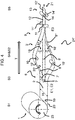
- FIG. 1 shows a method according to the invention or a device 24 according to the invention for producing multilayer sheet-metal strip packages (12 ') in a first embodiment.
- a first process step S1 unwound uncoated strip material 2 is unwound from a drum 23 by means of a feed arrangement 1 and fed.
- the strip material 2 comprises a top 19 and a bottom 20 and has a width B1 and a thickness D1, which is shown only schematically in the drawings, the width B1 extending from a first long side and a second long side of the strip material 2 and is oriented transversely to a transport direction T of the strip material 2.
- the width B1 is 2500mm without being limited thereto.
- the thickness D1 of the strip material 2 is constant in the transport direction T.
- the thickness D1 may alternatively be designed variable.
- the band material 2 is made of a ferromagnetic metal, without being limited thereto.
- the process step S1 is followed by the process step S2, in which the strip material 2 is coated in a coating arrangement 3 with a plastic coating becomes.
- an insulating varnish is used as the coating material.
- an adhesive, baked enamel, or visco-elastic polymer is used as a coating material.
- the strip material 2 is passed through two vertically arranged coating rolls 4, 4 '.
- the lower coating roll 4 ' is supplied by a material reservoir 5, as shown.
- the upper coating roller 4 is also supplied with the coating material by a material reservoir 5 'not shown in the figures.
- a plurality of juxtaposed coating rollers 4 wet the top 19 and / or the bottom 20 of the strip material 2 and areas are kept free of coating material.
- any other surface coating such as spray coating, powder coating or also point application of the coating material is conceivable.
- the process step S2 is followed by the process step S3, in which the strip material 2 is divided into three sheet metal strips 8, 8 ', 8 "in a strip subassembly 6, without the number being limited thereto, for which purpose two rotating cutting plates 7, 7' cut the strip
- the cutting can alternatively also be effected by means of a laser or a water jet
- the sheet metal strips 8, 8 ', 8 "produced in this case have an equal width B2 with respect to one another in the present case. It is also conceivable that in each case a part number of the sheet metal strips 8 has a different width B2.
- the metal strips 8, 8 ', 8 are in an imaginary plane E1, E2 transversely to the transport direction T, in which the cutting discs 7, 7' are arranged, further connected to the fed strip material 2, so that the longitudinal splitting takes place in a continuous process.
- the process step S3 is followed by the process step S4, in which the previously produced sheet metal strips 8, 8 ', 8 "are continuously guided over one another by means of a guide arrangement 9.
- the two outer sheet metal strips 8, 8" are deflected via deflecting rollers 10, 10' and so the middle sheet metal strip 8 'positioned between them.
- a three-layer sheet-metal strip package 12 results, the three Sheet metal strips 8, 8 ', 8 "are electrically separated from each other by the previously applied coating of insulating lacquer
- the distance, the sheet metal strips 8' and 8" on the guide rollers 10 and 10 'between the parting planes E1 and E2 and the union plane E3 cover in the illustrated embodiment is greater than the distance traveled by the straight in the direction of transport T sheet metal strip 8 between the parting planes E1 and E2 and the union plane E3.
- the metal strip 8 is likewise guided over deflecting rollers, so that the distance of the metal strip 8 between the parting planes E1 or E2 and the union plane E3 is substantially identical to the travel distance of the metal strips 8 'and 8 "
- at least two different widths B2 have, so that it is also conceivable that in each case the sheet metal strips 8, which have a same width B2, are superimposed and thus a plurality of sheet metal strip packages 12 are formed, of several pairs of guide rollers 11, 11 ' be recorded.
- the process step S4 is followed by the process step S5, in which the sheet metal strip package 12 is rolled by means of a rolling arrangement 13.
- the metal strip package 12 is guided by two vertically arranged rolling rollers 14, 14 ', which act on the sheet metal strip package 12 with a defined force.
- the force is chosen such that the coating material is evenly distributed between the sheet-metal strips 8, 8 ', 8 "or air inclusions are pressed out, but it is also conceivable that the force is chosen so large that the sheet-metal strips 8 , 8 ', 8 "experience a plastic deformation.
- the rolling rolls 14, 14 ' can also be heated.
- the insulating varnish hardens on a subsequent cooling-down path 21 and connects the individual layers of the sheet-metal strip packets 12 'in a materially bonded manner.
- For cold-curing coating materials can be dispensed with the heat.
- FIG. 2 a process step S6 following the process step S5 and an arrangement representing this process step S6 are shown.
- a contouring 15 laminated cores 17, 17' in the form of segmented Statorschwkernen for electric motors, without being limited to this form.
- the contouring 15 laminated cores are produced in the form of non-segmented stator or rotor cores, in particular as 360 ° -rades, as well as segmented rotor cores.
- the individual sheet metal layers of the laminated cores 12 ' are connected by the insulating material cohesively.
- the cutting tool 16 is shown for clarity.
- the contouring arrangement 15 can comprise a guide plate with serrations, an insert and an ejector. It is also conceivable that in the contouring 15 a laser or water jet cutting takes place instead of a fine cutting. For components with lower vorhalttechniksanssenen a normal punch as contouring 15 is conceivable.
- a process step S7 downstream of the process step S5 and an arrangement representing this process step S7 are shown.
- the rolled sheet metal strip package 12 ' is rolled up by means of a roll-up arrangement 22 onto a drum 23' to form a coil, also called a coil.
- the coil can be distributed as a semi-finished product or fed to a further processing process, for example in a separate punching system.
- the drum 23 'with the sheet-metal strip packages 12' serves as a strip material for the process step S1 described above and the process sequence FIG. 1 passes.
- FIG. 4 a method according to the invention or a device 24 'according to the invention for producing multilayer sheet metal strip packages (12') is shown in a second embodiment.
- the method or device 24 'differs from the method or device disclosed in US Pat FIG. 1 is shown only by the arrangement of the process step of the coating or the positioning of the coating arrangement 3 '. Coating by means of a coating arrangement 3 'of the upper side 19' and underside 20 'takes place within the guide arrangement 9.
- two painting units 18, 18' are arranged between the sheet metal strips 8, 8 ', 8 ", which hold the sheet metal strips 8, 8', 8 "in the spray painting process surface coat.
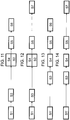
- FIG. 5 illustrates the process based on the illustrated flowchart, which is characterized by the synopsis of the previously described FIGS. 1 and 2 results.
- FIG. 6 shows the flow chart of the process, which is characterized by the synopsis of FIGS. 1 and 3 results. Reference should therefore be made at this point to the previous explanations.
- FIG. 7 a possible embodiment of the method is shown, whose process sequence is based on the process sequence FIG. 6 differs in that the process step S2 is omitted.
- the rolling process S5 can be dispensed with the supply of heat or the rolling process can according to the in FIG. 8 omitted fourth possible process sequence omitted.
- FIG. 9 another possible process sequence of a method according to the invention for the production of multi-layer sheet-metal strip packages 12 is illustrated with reference to a flow chart.
- the process sequence FIG. 9 differs from the process sequence FIG. 5 in that the order of the process steps S2 and S3 is reversed. In this respect, the similarities to the explanations to FIG. 5 directed.
- the uncoated strip material 2 is first divided into a plurality of sheet metal strips 8, 8 ', 8 "Subsequently, a flat surface is applied to the sheet metal strips 8, 8', 8" on an upper side 19 'and a lower side 20' Plastic coating applied in a coating arrangement 3.
- a flat surface is applied to the sheet metal strips 8, 8', 8" on an upper side 19 'and a lower side 20'
- Plastic coating applied in a coating arrangement 3.
- FIG. 10 a possible process sequence of a method according to the invention for the production of multi-layer sheet-metal strip packages 12 is illustrated with reference to a flowchart, which is based on the process sequence FIG. 9 differs in that the process step S7 is omitted and the process step S6 directly follows the process step S5.
- FIG. 11 a possible process sequence of a method according to the invention for the production of multi-layer sheet-metal strip packages 12 is shown with reference to a flow chart, which is characterized by the synopsis of FIGS. 4 and 2 results. Reference should therefore be made at this point to the previous explanations.
- FIG. 12 a possible process sequence of a method according to the invention for the production of multi-layer sheet-metal strip packages 12 is shown with reference to a flow chart, which is characterized by the synopsis of FIGS. 4 and 3 results. Reference should therefore be made at this point to the previous explanations.
- FIG. 13 another possible process sequence of a method according to the invention for the production of multi-layer sheet-metal strip packages 12 is illustrated with reference to a flow chart.
- the process sequence FIG. 13 differs from the process sequence FIG. 5 in that, in step S1 ', strip material 2, which has been previously coated, is unwound from a drum 23 and fed to the process, and process step S2 is omitted.
- the previously applied coating is made of an insulating varnish. But it is also possible that an adhesive, baked enamel, insulating varnish or visco-elastic polymer is used.
- the process steps from S3 balance with the process steps FIG. 5 so for the similarities in a nutshell on the remarks too FIG. 5 is referenced.
- FIG. 14 another possible process sequence of a method according to the invention for the production of multi-layer sheet-metal strip packages 12 is illustrated with reference to a flow chart.
- the process sequence FIG. 14 differs from the process sequence FIG. 13 in that the process step S6 is replaced by the process step S7.
Landscapes
- Engineering & Computer Science (AREA)
- Mechanical Engineering (AREA)
- Power Engineering (AREA)
- Manufacturing & Machinery (AREA)
- Application Of Or Painting With Fluid Materials (AREA)
- Laminated Bodies (AREA)
- Manufacture Of Motors, Generators (AREA)
- Manufacturing Cores, Coils, And Magnets (AREA)
Applications Claiming Priority (1)
| Application Number | Priority Date | Filing Date | Title |
|---|---|---|---|
| DE102018109008.0A DE102018109008B3 (de) | 2018-04-16 | 2018-04-16 | Verfahren und Vorrichtung zur Herstellung von mehrlagigen Blechstreifenpaketen |
Publications (2)
| Publication Number | Publication Date |
|---|---|
| EP3557734A1 true EP3557734A1 (fr) | 2019-10-23 |
| EP3557734B1 EP3557734B1 (fr) | 2021-01-06 |
Family
ID=65904323
Family Applications (1)
| Application Number | Title | Priority Date | Filing Date |
|---|---|---|---|
| EP19164602.5A Active EP3557734B1 (fr) | 2018-04-16 | 2019-03-22 | Procédé et dispositif de fabrication de paquets de bandes de tôles multicouche |
Country Status (6)
| Country | Link |
|---|---|
| US (1) | US20190315112A1 (fr) |
| EP (1) | EP3557734B1 (fr) |
| JP (1) | JP2019186553A (fr) |
| KR (1) | KR20190120707A (fr) |
| CN (1) | CN110385341A (fr) |
| DE (1) | DE102018109008B3 (fr) |
Families Citing this family (6)
| Publication number | Priority date | Publication date | Assignee | Title |
|---|---|---|---|---|
| DE102019213658A1 (de) | 2019-09-09 | 2021-03-11 | Elringklinger Ag | Verfahren zur Herstellung eines Blechstapels, Blechstapel, Maschinenbauteil und Elektromotor |
| DE102020208689A1 (de) | 2020-07-10 | 2022-01-13 | Elringklinger Ag | Verbindungsmaterial, Blechstapel, Maschinenbauteil und Elektromotor |
| EP4032629A1 (fr) * | 2021-01-25 | 2022-07-27 | Primetals Technologies Germany GmbH | Mesure de la planéité dans les trains de laminoir pour l'aluminium |
| CN115765227B (zh) * | 2022-11-18 | 2024-02-02 | 南通通达矽钢冲压科技有限公司 | 一种高材料利用率的自粘极靴铁芯结构 |
| CN120038569B (zh) * | 2025-04-23 | 2025-07-04 | 昶辰(佛山)特殊钢有限公司 | 一种层板加工方法及产线 |
| CN121402444B (zh) * | 2025-12-26 | 2026-04-07 | 益阳金能新材料有限责任公司 | 一种碳钢-高铬铸铁复合高耐磨板材及其制备方法 |
Citations (2)
| Publication number | Priority date | Publication date | Assignee | Title |
|---|---|---|---|---|
| DE10032506A1 (de) * | 2000-07-05 | 2002-01-17 | Kienle & Spiess Stanz & Druck | Verfahren zur Herstellung von Massivkernen aus Lamellen |
| EP2139011A1 (fr) * | 2007-04-13 | 2009-12-30 | Hitachi Metals, Ltd. | Noyau magnetique pour antenne, procede de fabrication d'un noyau magnetique pour antenne et antenne |
Family Cites Families (12)
| Publication number | Priority date | Publication date | Assignee | Title |
|---|---|---|---|---|
| DE3110339C2 (de) | 1981-03-17 | 1984-09-27 | Thyssen Industrie Ag, 4300 Essen | Verfahren zum Herstellen eines Blechpakets für einen Langstator-Linearmotor |
| DE3820997A1 (de) | 1988-06-22 | 1989-12-28 | Bwg Bergwerk Walzwerk | Vorrichtung zum separieren von bandstreifen eines laengsgeteilten bandes, insbesondere metallbandes |
| US5018267A (en) * | 1989-09-05 | 1991-05-28 | Armco Inc. | Method of forming a laminate |
| JPH09183147A (ja) * | 1995-12-28 | 1997-07-15 | Mitsui Petrochem Ind Ltd | 多層積層体の製造方法 |
| DE10110494C1 (de) * | 2001-02-14 | 2002-12-05 | Lohmann Therapie Syst Lts | Verfahren und Vorrichtung zur Herstellung dünner Plättchen aus einem Wirkstofffilm |
| DE10257396A1 (de) | 2002-12-06 | 2004-06-24 | Basf Ag | Verbundelemente, insbesondere Karosserieteile |
| DE10331023A1 (de) | 2003-07-10 | 2005-02-17 | Bwg Bergwerk- Und Walzwerk-Maschinenbau Gmbh | Vorrichtung und Verfahren zum Separieren von Bandstreifen nach der Längsteilung eines Bandes, insbesondere Metallbandes |
| JP2005297393A (ja) | 2004-04-13 | 2005-10-27 | Nippon Steel Corp | 低鉄損複数層電磁鋼板とその製造方法及び装置 |
| JP6086098B2 (ja) * | 2014-06-23 | 2017-03-01 | Jfeスチール株式会社 | 積層電磁鋼板およびその製造方法 |
| DE102014110252A1 (de) | 2014-07-21 | 2016-01-21 | Thyssenkrupp Ag | Vorrichtung und Verfahren zur Herstellung von Verbundblechen durch Mehrfachkaschierung |
| DE102014014976A1 (de) | 2014-10-14 | 2016-04-14 | Thyssenkrupp Ag | Verbundwerkstoff |
| DE102017108306A1 (de) | 2017-04-19 | 2018-10-25 | Bwg Bergwerk- Und Walzwerk-Maschinenbau Gmbh | Anlage und Verfahren zum Längsteilen eines Bandes |
-
2018
- 2018-04-16 DE DE102018109008.0A patent/DE102018109008B3/de not_active Expired - Fee Related
-
2019
- 2019-03-22 US US16/361,293 patent/US20190315112A1/en not_active Abandoned
- 2019-03-22 EP EP19164602.5A patent/EP3557734B1/fr active Active
- 2019-04-11 KR KR1020190042306A patent/KR20190120707A/ko not_active Withdrawn
- 2019-04-12 CN CN201910294089.XA patent/CN110385341A/zh not_active Withdrawn
- 2019-04-15 JP JP2019076933A patent/JP2019186553A/ja active Pending
Patent Citations (2)
| Publication number | Priority date | Publication date | Assignee | Title |
|---|---|---|---|---|
| DE10032506A1 (de) * | 2000-07-05 | 2002-01-17 | Kienle & Spiess Stanz & Druck | Verfahren zur Herstellung von Massivkernen aus Lamellen |
| EP2139011A1 (fr) * | 2007-04-13 | 2009-12-30 | Hitachi Metals, Ltd. | Noyau magnetique pour antenne, procede de fabrication d'un noyau magnetique pour antenne et antenne |
Also Published As
| Publication number | Publication date |
|---|---|
| CN110385341A (zh) | 2019-10-29 |
| JP2019186553A (ja) | 2019-10-24 |
| US20190315112A1 (en) | 2019-10-17 |
| DE102018109008B3 (de) | 2019-09-05 |
| EP3557734B1 (fr) | 2021-01-06 |
| KR20190120707A (ko) | 2019-10-24 |
Similar Documents
| Publication | Publication Date | Title |
|---|---|---|
| EP3557734B1 (fr) | Procédé et dispositif de fabrication de paquets de bandes de tôles multicouche | |
| EP2883692A1 (fr) | Dispositif et procédé de liaison de pièces en tôle et d'un paquet de tôles | |
| DE102013020662B4 (de) | Verfahren zur Herstellung von Lamellen für ein Lamellenpaket, insbesondere für elektrische Maschinen und Generatoren, Vorrichtung mit wenigstens einer Stanzpresse sowie nach dem Verfahren hergestellte Lamelle und Lamellenpaket | |
| DE102014011474A1 (de) | Lamellenpaket sowie Verfahren zu dessen Herstellung | |
| EP3850735A1 (fr) | Procédé et dispositif pour relier des pièces de tôles de façon à former des paquets de tôles | |
| DE102014017149A1 (de) | Verfahren zur Herstellung von Lamellenpaketen und Anlage zur Durchführung des Verfahrens | |
| EP3316457A1 (fr) | Dispositif et procédé de liaison de parties de tôles à un paquet de tôles | |
| EP3207547B1 (fr) | Bobine et procédé de production d'un stratifié de bandes magnétiques enroulées en une bobine | |
| EP3089335B1 (fr) | Dispositif et procédé de liaison de parties de tôles à un paquet de tôles | |
| DE112023003735T5 (de) | Verfahren zur herstellung eines mehrschichtmaterials vor der stanzpresse für geblechte elektromotorkomponenten | |
| EP3593439A1 (fr) | Dispositif et procédé de liaison de pièces de tôle pour obtenir un noyau feuilleté | |
| DE102015106968A1 (de) | Produktionsanlage und Verfahren zur Herstellung von KFZ-Kennzeichenrohlingen | |
| DE102015208870A1 (de) | Verfahren zur Herstellung eines Blechpakets | |
| EP3182570B1 (fr) | Procédé de revêtement d'un noyau électromagnétique | |
| DE2347484B2 (de) | Verfahren zum Stanzen von im wesentlich ringsektorförmigen Blechsegmenten für Statorblechpakete elektrischer Maschinen | |
| DE2753586A1 (de) | Ein- oder beidseitig isoliertes, lackiertes o.dgl. blech fuer elektrische maschinen wie transformatoren, drosselspulen, zuendspulen, motoren, generatoren o.dgl. | |
| EP3503139B1 (fr) | Procédé et produit semi-fini de fabrication au moins un paquet-section de un composant magnétique doux | |
| DE102012000705A1 (de) | Verfahren zum Herstellen von beschichteten Magnetkernen | |
| DE102010002003A1 (de) | Elektromotorkörper und Verfahren zur Herstellung eines Elektromotorkörpers | |
| DE102016000399A1 (de) | Verfahren zum Herstellen eines Blechpakets für eine elektrische Maschine | |
| DE102007037167A1 (de) | Einlagige Flachspule auf Substrat | |
| DE102022110938A1 (de) | Verfahren zur zumindest teilumfänglichen Herstellung eines Blechpakets für ein Aktivteil einer elektrischen Maschine | |
| EP0708460A2 (fr) | Fabrication de tÔles de noyau | |
| DE102023132788A1 (de) | Rotor für eine Axialflussmaschine | |
| DE102024120952A1 (de) | Vorrichtung zur Herstellung eines Blechelements und Blechelement |
Legal Events
| Date | Code | Title | Description |
|---|---|---|---|
| PUAI | Public reference made under article 153(3) epc to a published international application that has entered the european phase |
Free format text: ORIGINAL CODE: 0009012 |
|
| STAA | Information on the status of an ep patent application or granted ep patent |
Free format text: STATUS: THE APPLICATION HAS BEEN PUBLISHED |
|
| AK | Designated contracting states |
Kind code of ref document: A1 Designated state(s): AL AT BE BG CH CY CZ DE DK EE ES FI FR GB GR HR HU IE IS IT LI LT LU LV MC MK MT NL NO PL PT RO RS SE SI SK SM TR |
|
| AX | Request for extension of the european patent |
Extension state: BA ME |
|
| STAA | Information on the status of an ep patent application or granted ep patent |
Free format text: STATUS: REQUEST FOR EXAMINATION WAS MADE |
|
| 17P | Request for examination filed |
Effective date: 20200327 |
|
| RBV | Designated contracting states (corrected) |
Designated state(s): AL AT BE BG CH CY CZ DE DK EE ES FI FR GB GR HR HU IE IS IT LI LT LU LV MC MK MT NL NO PL PT RO RS SE SI SK SM TR |
|
| GRAP | Despatch of communication of intention to grant a patent |
Free format text: ORIGINAL CODE: EPIDOSNIGR1 |
|
| STAA | Information on the status of an ep patent application or granted ep patent |
Free format text: STATUS: GRANT OF PATENT IS INTENDED |
|
| RIC1 | Information provided on ipc code assigned before grant |
Ipc: B65H 35/02 20060101ALI20200715BHEP Ipc: B21B 1/38 20060101ALI20200715BHEP Ipc: H02K 1/06 20060101ALI20200715BHEP Ipc: B23D 31/00 20060101ALN20200715BHEP Ipc: H02K 15/02 20060101AFI20200715BHEP Ipc: B23D 19/00 20060101ALN20200715BHEP Ipc: B21B 15/00 20060101ALI20200715BHEP |
|
| INTG | Intention to grant announced |
Effective date: 20200804 |
|
| GRAS | Grant fee paid |
Free format text: ORIGINAL CODE: EPIDOSNIGR3 |
|
| GRAA | (expected) grant |
Free format text: ORIGINAL CODE: 0009210 |
|
| STAA | Information on the status of an ep patent application or granted ep patent |
Free format text: STATUS: THE PATENT HAS BEEN GRANTED |
|
| AK | Designated contracting states |
Kind code of ref document: B1 Designated state(s): AL AT BE BG CH CY CZ DE DK EE ES FI FR GB GR HR HU IE IS IT LI LT LU LV MC MK MT NL NO PL PT RO RS SE SI SK SM TR |
|
| REG | Reference to a national code |
Ref country code: GB Ref legal event code: FG4D Free format text: NOT ENGLISH |
|
| REG | Reference to a national code |
Ref country code: AT Ref legal event code: REF Ref document number: 1353434 Country of ref document: AT Kind code of ref document: T Effective date: 20210115 Ref country code: CH Ref legal event code: EP |
|
| REG | Reference to a national code |
Ref country code: DE Ref legal event code: R096 Ref document number: 502019000631 Country of ref document: DE |
|
| REG | Reference to a national code |
Ref country code: IE Ref legal event code: FG4D Free format text: LANGUAGE OF EP DOCUMENT: GERMAN |
|
| REG | Reference to a national code |
Ref country code: NL Ref legal event code: MP Effective date: 20210106 |
|
| REG | Reference to a national code |
Ref country code: LT Ref legal event code: MG9D |
|
| PG25 | Lapsed in a contracting state [announced via postgrant information from national office to epo] |
Ref country code: GR Free format text: LAPSE BECAUSE OF FAILURE TO SUBMIT A TRANSLATION OF THE DESCRIPTION OR TO PAY THE FEE WITHIN THE PRESCRIBED TIME-LIMIT Effective date: 20210407 Ref country code: FI Free format text: LAPSE BECAUSE OF FAILURE TO SUBMIT A TRANSLATION OF THE DESCRIPTION OR TO PAY THE FEE WITHIN THE PRESCRIBED TIME-LIMIT Effective date: 20210106 Ref country code: HR Free format text: LAPSE BECAUSE OF FAILURE TO SUBMIT A TRANSLATION OF THE DESCRIPTION OR TO PAY THE FEE WITHIN THE PRESCRIBED TIME-LIMIT Effective date: 20210106 Ref country code: BG Free format text: LAPSE BECAUSE OF FAILURE TO SUBMIT A TRANSLATION OF THE DESCRIPTION OR TO PAY THE FEE WITHIN THE PRESCRIBED TIME-LIMIT Effective date: 20210406 Ref country code: NO Free format text: LAPSE BECAUSE OF FAILURE TO SUBMIT A TRANSLATION OF THE DESCRIPTION OR TO PAY THE FEE WITHIN THE PRESCRIBED TIME-LIMIT Effective date: 20210406 Ref country code: PT Free format text: LAPSE BECAUSE OF FAILURE TO SUBMIT A TRANSLATION OF THE DESCRIPTION OR TO PAY THE FEE WITHIN THE PRESCRIBED TIME-LIMIT Effective date: 20210506 Ref country code: LT Free format text: LAPSE BECAUSE OF FAILURE TO SUBMIT A TRANSLATION OF THE DESCRIPTION OR TO PAY THE FEE WITHIN THE PRESCRIBED TIME-LIMIT Effective date: 20210106 |
|
| PG25 | Lapsed in a contracting state [announced via postgrant information from national office to epo] |
Ref country code: SE Free format text: LAPSE BECAUSE OF FAILURE TO SUBMIT A TRANSLATION OF THE DESCRIPTION OR TO PAY THE FEE WITHIN THE PRESCRIBED TIME-LIMIT Effective date: 20210106 Ref country code: RS Free format text: LAPSE BECAUSE OF FAILURE TO SUBMIT A TRANSLATION OF THE DESCRIPTION OR TO PAY THE FEE WITHIN THE PRESCRIBED TIME-LIMIT Effective date: 20210106 Ref country code: LV Free format text: LAPSE BECAUSE OF FAILURE TO SUBMIT A TRANSLATION OF THE DESCRIPTION OR TO PAY THE FEE WITHIN THE PRESCRIBED TIME-LIMIT Effective date: 20210106 Ref country code: PL Free format text: LAPSE BECAUSE OF FAILURE TO SUBMIT A TRANSLATION OF THE DESCRIPTION OR TO PAY THE FEE WITHIN THE PRESCRIBED TIME-LIMIT Effective date: 20210106 |
|
| PG25 | Lapsed in a contracting state [announced via postgrant information from national office to epo] |
Ref country code: IS Free format text: LAPSE BECAUSE OF FAILURE TO SUBMIT A TRANSLATION OF THE DESCRIPTION OR TO PAY THE FEE WITHIN THE PRESCRIBED TIME-LIMIT Effective date: 20210506 |
|
| REG | Reference to a national code |
Ref country code: DE Ref legal event code: R097 Ref document number: 502019000631 Country of ref document: DE |
|
| PG25 | Lapsed in a contracting state [announced via postgrant information from national office to epo] |
Ref country code: SM Free format text: LAPSE BECAUSE OF FAILURE TO SUBMIT A TRANSLATION OF THE DESCRIPTION OR TO PAY THE FEE WITHIN THE PRESCRIBED TIME-LIMIT Effective date: 20210106 Ref country code: EE Free format text: LAPSE BECAUSE OF FAILURE TO SUBMIT A TRANSLATION OF THE DESCRIPTION OR TO PAY THE FEE WITHIN THE PRESCRIBED TIME-LIMIT Effective date: 20210106 Ref country code: CZ Free format text: LAPSE BECAUSE OF FAILURE TO SUBMIT A TRANSLATION OF THE DESCRIPTION OR TO PAY THE FEE WITHIN THE PRESCRIBED TIME-LIMIT Effective date: 20210106 Ref country code: MC Free format text: LAPSE BECAUSE OF FAILURE TO SUBMIT A TRANSLATION OF THE DESCRIPTION OR TO PAY THE FEE WITHIN THE PRESCRIBED TIME-LIMIT Effective date: 20210106 |
|
| PLBE | No opposition filed within time limit |
Free format text: ORIGINAL CODE: 0009261 |
|
| STAA | Information on the status of an ep patent application or granted ep patent |
Free format text: STATUS: NO OPPOSITION FILED WITHIN TIME LIMIT |
|
| PG25 | Lapsed in a contracting state [announced via postgrant information from national office to epo] |
Ref country code: DK Free format text: LAPSE BECAUSE OF FAILURE TO SUBMIT A TRANSLATION OF THE DESCRIPTION OR TO PAY THE FEE WITHIN THE PRESCRIBED TIME-LIMIT Effective date: 20210106 Ref country code: SK Free format text: LAPSE BECAUSE OF FAILURE TO SUBMIT A TRANSLATION OF THE DESCRIPTION OR TO PAY THE FEE WITHIN THE PRESCRIBED TIME-LIMIT Effective date: 20210106 Ref country code: RO Free format text: LAPSE BECAUSE OF FAILURE TO SUBMIT A TRANSLATION OF THE DESCRIPTION OR TO PAY THE FEE WITHIN THE PRESCRIBED TIME-LIMIT Effective date: 20210106 |
|
| 26N | No opposition filed |
Effective date: 20211007 |
|
| REG | Reference to a national code |
Ref country code: BE Ref legal event code: MM Effective date: 20210331 |
|
| PG25 | Lapsed in a contracting state [announced via postgrant information from national office to epo] |
Ref country code: FR Free format text: LAPSE BECAUSE OF NON-PAYMENT OF DUE FEES Effective date: 20210331 Ref country code: LU Free format text: LAPSE BECAUSE OF NON-PAYMENT OF DUE FEES Effective date: 20210322 Ref country code: IE Free format text: LAPSE BECAUSE OF NON-PAYMENT OF DUE FEES Effective date: 20210322 Ref country code: AL Free format text: LAPSE BECAUSE OF FAILURE TO SUBMIT A TRANSLATION OF THE DESCRIPTION OR TO PAY THE FEE WITHIN THE PRESCRIBED TIME-LIMIT Effective date: 20210106 Ref country code: ES Free format text: LAPSE BECAUSE OF FAILURE TO SUBMIT A TRANSLATION OF THE DESCRIPTION OR TO PAY THE FEE WITHIN THE PRESCRIBED TIME-LIMIT Effective date: 20210106 |
|
| PG25 | Lapsed in a contracting state [announced via postgrant information from national office to epo] |
Ref country code: SI Free format text: LAPSE BECAUSE OF FAILURE TO SUBMIT A TRANSLATION OF THE DESCRIPTION OR TO PAY THE FEE WITHIN THE PRESCRIBED TIME-LIMIT Effective date: 20210106 |
|
| PG25 | Lapsed in a contracting state [announced via postgrant information from national office to epo] |
Ref country code: IT Free format text: LAPSE BECAUSE OF FAILURE TO SUBMIT A TRANSLATION OF THE DESCRIPTION OR TO PAY THE FEE WITHIN THE PRESCRIBED TIME-LIMIT Effective date: 20210106 |
|
| PG25 | Lapsed in a contracting state [announced via postgrant information from national office to epo] |
Ref country code: IS Free format text: LAPSE BECAUSE OF FAILURE TO SUBMIT A TRANSLATION OF THE DESCRIPTION OR TO PAY THE FEE WITHIN THE PRESCRIBED TIME-LIMIT Effective date: 20210506 |
|
| PG25 | Lapsed in a contracting state [announced via postgrant information from national office to epo] |
Ref country code: BE Free format text: LAPSE BECAUSE OF NON-PAYMENT OF DUE FEES Effective date: 20210331 |
|
| REG | Reference to a national code |
Ref country code: CH Ref legal event code: PL |
|
| PG25 | Lapsed in a contracting state [announced via postgrant information from national office to epo] |
Ref country code: LI Free format text: LAPSE BECAUSE OF NON-PAYMENT OF DUE FEES Effective date: 20220331 Ref country code: CH Free format text: LAPSE BECAUSE OF NON-PAYMENT OF DUE FEES Effective date: 20220331 |
|
| PG25 | Lapsed in a contracting state [announced via postgrant information from national office to epo] |
Ref country code: NL Free format text: LAPSE BECAUSE OF NON-PAYMENT OF DUE FEES Effective date: 20210206 Ref country code: CY Free format text: LAPSE BECAUSE OF FAILURE TO SUBMIT A TRANSLATION OF THE DESCRIPTION OR TO PAY THE FEE WITHIN THE PRESCRIBED TIME-LIMIT Effective date: 20210106 |
|
| PG25 | Lapsed in a contracting state [announced via postgrant information from national office to epo] |
Ref country code: HU Free format text: LAPSE BECAUSE OF FAILURE TO SUBMIT A TRANSLATION OF THE DESCRIPTION OR TO PAY THE FEE WITHIN THE PRESCRIBED TIME-LIMIT; INVALID AB INITIO Effective date: 20190322 |
|
| GBPC | Gb: european patent ceased through non-payment of renewal fee |
Effective date: 20230322 |
|
| PG25 | Lapsed in a contracting state [announced via postgrant information from national office to epo] |
Ref country code: GB Free format text: LAPSE BECAUSE OF NON-PAYMENT OF DUE FEES Effective date: 20230322 |
|
| PG25 | Lapsed in a contracting state [announced via postgrant information from national office to epo] |
Ref country code: GB Free format text: LAPSE BECAUSE OF NON-PAYMENT OF DUE FEES Effective date: 20230322 |
|
| PG25 | Lapsed in a contracting state [announced via postgrant information from national office to epo] |
Ref country code: MK Free format text: LAPSE BECAUSE OF FAILURE TO SUBMIT A TRANSLATION OF THE DESCRIPTION OR TO PAY THE FEE WITHIN THE PRESCRIBED TIME-LIMIT Effective date: 20210106 |
|
| PG25 | Lapsed in a contracting state [announced via postgrant information from national office to epo] |
Ref country code: MT Free format text: LAPSE BECAUSE OF FAILURE TO SUBMIT A TRANSLATION OF THE DESCRIPTION OR TO PAY THE FEE WITHIN THE PRESCRIBED TIME-LIMIT Effective date: 20210106 |
|
| REG | Reference to a national code |
Ref country code: AT Ref legal event code: MM01 Ref document number: 1353434 Country of ref document: AT Kind code of ref document: T Effective date: 20240322 |
|
| PG25 | Lapsed in a contracting state [announced via postgrant information from national office to epo] |
Ref country code: AT Free format text: LAPSE BECAUSE OF NON-PAYMENT OF DUE FEES Effective date: 20240322 |
|
| PG25 | Lapsed in a contracting state [announced via postgrant information from national office to epo] |
Ref country code: TR Free format text: LAPSE BECAUSE OF FAILURE TO SUBMIT A TRANSLATION OF THE DESCRIPTION OR TO PAY THE FEE WITHIN THE PRESCRIBED TIME-LIMIT Effective date: 20210106 |
|
| PGFP | Annual fee paid to national office [announced via postgrant information from national office to epo] |
Ref country code: DE Payment date: 20260313 Year of fee payment: 8 |
|
| PGFP | Annual fee paid to national office [announced via postgrant information from national office to epo] |
Ref country code: AT Payment date: 20260410 Year of fee payment: 5 |