EP3557736A1 - Moteur à réluctance synchrone à démarrage en ligne et rotor associé - Google Patents
Moteur à réluctance synchrone à démarrage en ligne et rotor associé Download PDFInfo
- Publication number
- EP3557736A1 EP3557736A1 EP17882054.4A EP17882054A EP3557736A1 EP 3557736 A1 EP3557736 A1 EP 3557736A1 EP 17882054 A EP17882054 A EP 17882054A EP 3557736 A1 EP3557736 A1 EP 3557736A1
- Authority
- EP
- European Patent Office
- Prior art keywords
- rotor
- reluctance motor
- synchronous reluctance
- line start
- conductor
- Prior art date
- Legal status (The legal status is an assumption and is not a legal conclusion. Google has not performed a legal analysis and makes no representation as to the accuracy of the status listed.)
- Granted
Links
Images



Classifications
-
- H—ELECTRICITY
- H02—GENERATION; CONVERSION OR DISTRIBUTION OF ELECTRIC POWER
- H02K—DYNAMO-ELECTRIC MACHINES
- H02K19/00—Synchronous motors or generators
- H02K19/02—Synchronous motors
- H02K19/14—Synchronous motors having additional short-circuited windings for starting as asynchronous motors
-
- H—ELECTRICITY
- H02—GENERATION; CONVERSION OR DISTRIBUTION OF ELECTRIC POWER
- H02K—DYNAMO-ELECTRIC MACHINES
- H02K19/00—Synchronous motors or generators
- H02K19/02—Synchronous motors
- H02K19/04—Synchronous motors for single-phase current
- H02K19/06—Motors having windings on the stator and a variable-reluctance soft-iron rotor without windings, e.g. inductor motors
-
- H—ELECTRICITY
- H02—GENERATION; CONVERSION OR DISTRIBUTION OF ELECTRIC POWER
- H02K—DYNAMO-ELECTRIC MACHINES
- H02K1/00—Details of the magnetic circuit
- H02K1/06—Details of the magnetic circuit characterised by the shape, form or construction
- H02K1/22—Rotating parts of the magnetic circuit
- H02K1/24—Rotor cores with salient poles ; Variable reluctance rotors
- H02K1/246—Variable reluctance rotors
-
- H—ELECTRICITY
- H02—GENERATION; CONVERSION OR DISTRIBUTION OF ELECTRIC POWER
- H02K—DYNAMO-ELECTRIC MACHINES
- H02K21/00—Synchronous motors having permanent magnets; Synchronous generators having permanent magnets
- H02K21/46—Motors having additional short-circuited winding for starting as an asynchronous motor
Definitions
- the present invention relates to a line start synchronous reluctance motor, and more particularly, to a line start synchronous reluctance motor and a rotor thereof capable of improving characteristics of the motor through an asymmetrical flux-barrier structure without changing the number of conductor bars.
- a line start synchronous reluctance motor is a motor using the principle that a rotating force is generated by a change in magnetic resistance according to rotation of a rotor and is widely used for a compressor or the like.
- a rotor of the line start synchronous reluctance motor includes a core formed by laminating a plurality of steel sheets, wherein the core has a plurality of flux barriers and a steel part on which the flux barrier is not formed.
- output of an induction-type motor changes according to combinations of the number of slots formed in a stator and the number of conductor bars formed in a rotor.
- the required performance characteristics are satisfied when forty-four conductor bars are disposed in a four-pole rotor, the required performance characteristics are not satisfied when forty-two or forty-eight conductor bars are disposed in the same four-pole rotor.
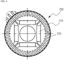
- FIG. 4 illustrates a permanent magnet (PM) motor which is line-started by a PM 720 being inserted into a rotor 700 of an induction-type motor that has conduction bars 710 as illustrated, as a rotor of a motor using a PM, such that motor efficiency is more improved during synchronized operation after self-starting as compared with the induction-type motor.
- PM permanent magnet
- the present invention is directed to providing a line start synchronous reluctance motor and a rotor thereof capable of improving characteristics of the motor through an asymmetrical flux-barrier structure without changing the number of conductor bars, thereby allowing the initial starting of the motor to be smoothly performed, which is advantageous in terms of torque ripple characteristics and die casting.
- the present invention provides a line start synchronous reluctance motor including: a rotor; a plurality of conductor bars disposed on a side of an outer circumferential portion of the rotor; and flux barriers formed at an inner side of the rotor so as to be close to the conductor bars, wherein the flux barriers, which are formed in separate regions of a rotor body that are arranged to have opposite polarities, are formed to be asymmetrical to each other.
- a shaft hole may be formed in an axial direction at the center of the rotor body having a cylindrical shape, conductor bar insertion holes may be formed at predetermined intervals at an inner side of the outer circumferential portion, and flux-barrier insertion holes may be formed between the shaft hole and the conductor bar insertion holes.
- the conductor bars may be arranged at predetermined intervals at a portion close to an outer circumferential portion of the rotor body.
- the conductor bars may be arranged asymmetrically in the separate regions of the rotor body that are arranged to have opposite polarities.
- the conductor bars may each include: a conductor bar body having a tapered portion whose width gradually narrows toward the center of the rotor body; and a conductor bar head portion in a semi-circular shape that is formed at each of both side ends of the conductor bar body.
- a first unit barrier may be formed between an inner side portion of one-side conductor bar and an inner side portion of the other-side conductor bar between which a maximum distance is formed inside the separate regions of the rotor body
- a second unit barrier may be repeatedly formed between an inner side portion of one-side conductor bar and an inner side portion of the other-side conductor bar between which a maximum distance is formed inside separate regions between the first unit barrier and the outer circumferential portion of the rotor body.
- the first unit barrier and the second unit barrier may be formed to have a shape that is bent toward the center of the rotor body.
- first and second may be used to describe various elements, but the elements are not limited by the terms. The terms are only used for the purpose of distinguishing one element from another element.
- a first element may be referred to as a second element while not departing from the scope of the present invention, and likewise, a second element may also be referred to as a first element.
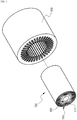
- FIG. 1 is a perspective view illustrating a stator and a rotor of a line start synchronous reluctance motor according to the present invention
- FIG. 2 is an exploded perspective view of the stator and the rotor of the line start synchronous reluctance motor according to the present invention
- FIG. 3 is a longitudinal cross-sectional view illustrating the stator and the rotor of the line start synchronous reluctance motor according to the present invention.
- the line start synchronous reluctance motor according to the present invention allows line starting to be smoothly performed without using an inverter during initial starting, which is advantageous in terms of torque ripple characteristics and die casting.
- the line start synchronous reluctance motor according to the present invention includes a rotor 100, conductor bars 200, and flux barriers 300.
- the rotor 100 is rotatably inserted into a stator 600.
- the rotor 100 includes a product of an extrusion method using die casting that is cut to a predetermined length.
- a shaft hole 111 having a predetermined diameter is formed in an axial direction at the center of a rotor body 110 having a cylindrical shape, conductor bar insertion holes 112 are formed at predetermined intervals at an inner side of an outer circumferential portion of the rotor 100, and the conductor bars 200 are disposed in uniform distribution.
- the flux barriers 300 are disposed in flux-barrier insertion holes 113 which are formed between the shaft hole 111 and the conductor bar insertion holes 112 so that characteristics of the motor are improved.
- opposite polarities may be repeatedly arranged in the rotor body 110, and the rotor body 110 may be divided into first, second, third, fourth, fifth, and sixth regions P1, P2, P3, P4, P5, and P6 whose polarities are different from each other.
- the conductor bars 200 are repeatedly arranged at predetermined intervals at a side of the outer circumferential portion of the rotor 100 along the outer circumferential portion. Forty-four conductor bars 200 are arranged at predetermined intervals at a portion close to an outer circumferential portion of the rotor body 110.
- Such conductor bars 200 each include a conductor bar body 220 having a tapered portion 210 whose width gradually narrows toward the center of the rotor body 110 and a conductor bar head portion 230 in a semi-circular shape that is formed at each of both side ends of the conductor bar body 220. In this way, the conductor bars 200 may be maintained at predetermined intervals.
- Seven conductor bars 200, eight conductor bars 200, seven conductor bars 200, seven conductor bars 200, eight conductor bars 200, and seven conductor bars 200 are arranged to be asymmetrical to each other in the first, second, third, fourth, fifth, and sixth separate regions P1, P2, P3, P4, P5, and P6, respectively, of the rotor body 110 that are arranged to have opposite polarities.
- the flux barriers 300 are repeatedly formed by being separated at predetermined intervals at an inner side of the rotor 100 so as to be close to the conductor bars 200.
- a first unit barrier 310 is formed between an inner side portion of one-side conductor bar 200 and an inner side portion of the other-side conductor bar 200 between which a maximum distance L is formed inside the separate regions of the rotor body 110.
- a second unit barrier 320 is formed between an inner side portion of one-side conductor bar 200 and an inner side portion of the other-side conductor bar 200 between which a maximum distance L' is formed inside separate regions between the first unit barrier 310 and the outer circumferential portion of the rotor body 110.
- another unit barrier having the same shape as the second unit barrier 230 is repeatedly formed at an inner portion of the second unit barrier 230. That is, the unit barriers are arranged in multiple layers. In this case, it is preferable that the unit barriers have a shape that is bent toward the center of the rotor body 110.
- the above-described rotor for a line start synchronous reluctance motor is formed by an extrusion method using die casting so that, first, the shaft hole 111 having a predetermined diameter is formed in an axial direction at the center of a rotor body 110 having a cylindrical shape, the conductor bar insertion holes 112 are formed at predetermined intervals at the inner side of the outer circumferential portion of the rotor, and multiple layers of the flux-barrier insertion holes 113, whose sizes vary, are formed between the shaft hole 111 and the conductor bar insertion holes 112.
- conductors and flux barriers are inserted or injected into the conductor bar insertion holes 112 and the multiple layers of the flux-barrier insertion holes 113, respectively, and hardened, and then both side surfaces of the rotor are processed, thereby obtaining the rotor.
- forty-four conductor bars 200 are arranged at predetermined intervals in the first, second, third, fourth, fifth, and sixth separate regions P1, P2, P3, P4, P5, and P6 in which opposite polarities are repeatedly arranged, and seven conductor bars 200, eight conductor bars 200, seven conductor bars 200, seven conductor bars 200, eight conductor bars 200, and seven conductor bars 200 are arranged to be asymmetrical to each other in the first, second, third, fourth, fifth, and sixth separate regions P1, P2, P3, P4, P5, and P6, respectively.
- the flux barriers 300 including the first unit barrier 310, the second unit barrier 320, and the like are formed in each of the first, second, third, fourth, fifth, and sixth separate regions P1, P2, P3, P4, P5, and P6, characteristics of the motor can be improved. That is, line-starting can be smoothly performed by uniformly distributing conductor bars during initial starting by using the asymmetrically-formed flux barriers 300, without changing the number of conductor bars 200 disposed in the rotor.
- the present invention relates to a line start synchronous reluctance motor that is usable in the field of motors.
Landscapes
- Engineering & Computer Science (AREA)
- Power Engineering (AREA)
- Synchronous Machinery (AREA)
Applications Claiming Priority (2)
| Application Number | Priority Date | Filing Date | Title |
|---|---|---|---|
| KR1020160173018A KR101904922B1 (ko) | 2016-12-16 | 2016-12-16 | 라인기동식 동기형 릴럭턴스 전동기 및 그 회전자 |
| PCT/KR2017/014637 WO2018110971A1 (fr) | 2016-12-16 | 2017-12-13 | Moteur à réluctance synchrone à démarrage en ligne et rotor associé |
Publications (3)
| Publication Number | Publication Date |
|---|---|
| EP3557736A1 true EP3557736A1 (fr) | 2019-10-23 |
| EP3557736A4 EP3557736A4 (fr) | 2020-07-22 |
| EP3557736B1 EP3557736B1 (fr) | 2021-07-07 |
Family
ID=62558928
Family Applications (1)
| Application Number | Title | Priority Date | Filing Date |
|---|---|---|---|
| EP17882054.4A Active EP3557736B1 (fr) | 2016-12-16 | 2017-12-13 | Moteur à réluctance synchrone à démarrage en ligne et rotor associé |
Country Status (4)
| Country | Link |
|---|---|
| US (1) | US11088603B2 (fr) |
| EP (1) | EP3557736B1 (fr) |
| KR (1) | KR101904922B1 (fr) |
| WO (1) | WO2018110971A1 (fr) |
Cited By (1)
| Publication number | Priority date | Publication date | Assignee | Title |
|---|---|---|---|---|
| FR3104651A1 (fr) * | 2019-12-13 | 2021-06-18 | Danfoss Commercial Compressors | Compresseur à spirales ayant un moteur à réluctance synchrone à démarrage direct sur le réseau (DOL) |
Families Citing this family (11)
| Publication number | Priority date | Publication date | Assignee | Title |
|---|---|---|---|---|
| US10916997B2 (en) * | 2017-11-28 | 2021-02-09 | Hamilton Sundstrand Corporation | Line start two-speed brushless motor |
| TWI676335B (zh) * | 2018-10-24 | 2019-11-01 | 台灣電產科技股份有限公司 | 轉子裝置及具有該轉子裝置的磁阻馬達 |
| TWI676336B (zh) * | 2018-10-24 | 2019-11-01 | 台灣電產科技股份有限公司 | 六極之轉子裝置及具有該六極之轉子裝置的磁阻馬達 |
| KR102649212B1 (ko) * | 2018-12-18 | 2024-03-18 | 한국전기연구원 | 직입구동 동기 릴럭턴스 전동기의 회전자 구조 및 그 제조방법 |
| CN110212724B (zh) * | 2019-06-19 | 2023-12-08 | 珠海格力电器股份有限公司 | 自起动同步磁阻电机及具有其的压缩机 |
| CN110635591B (zh) * | 2019-09-27 | 2025-03-07 | 珠海格力电器股份有限公司 | 同步磁阻电机 |
| CN114696493A (zh) * | 2020-12-25 | 2022-07-01 | 日本电产株式会社 | 同步磁阻电动机和电气产品 |
| KR102547221B1 (ko) * | 2021-07-08 | 2023-06-23 | 에스제이글로벌 주식회사 | 직입 구동방식의 영구자석 매입형 자기저항 동기모터의 회전자 및 그의 제조방법 |
| KR102682554B1 (ko) * | 2021-12-24 | 2024-07-05 | 김병국 | 직입형 자기저항 동기전동기 |
| CN118631005A (zh) | 2023-03-07 | 2024-09-10 | 日本电产株式会社 | 同步磁阻电机 |
| KR20260023721A (ko) * | 2024-08-12 | 2026-02-20 | 에스제이글로벌 주식회사 | 직입 구동방식의 영구자석 매입형 자기저항 동기모터의 회전자 단위 원판 |
Family Cites Families (18)
| Publication number | Priority date | Publication date | Assignee | Title |
|---|---|---|---|---|
| US2483848A (en) * | 1946-12-14 | 1949-10-04 | Holtzer Cabot Inc | Synchronous motor |
| US3597646A (en) | 1970-01-26 | 1971-08-03 | Peter John Lawrenson | Dynamoelectric machines |
| GB1347561A (en) * | 1970-01-30 | 1974-02-27 | Nat Res Dev | Dynamo-electric machines of the reluctance type |
| US3721844A (en) | 1971-05-27 | 1973-03-20 | Nat Res Dev | Reluctance motors |
| GB1448990A (en) * | 1972-12-22 | 1976-09-08 | Nat Res Dev | Roatary and linear electric machines |
| JP3051340B2 (ja) * | 1996-06-18 | 2000-06-12 | オークマ株式会社 | 同期電動機 |
| US6088906A (en) * | 1997-09-16 | 2000-07-18 | Ut-Battelle, Llc | Method of manufacturing squirrel cage rotors |
| JP2003259615A (ja) | 2002-03-04 | 2003-09-12 | Mitsubishi Electric Corp | リラクタンスモータ |
| CN1726629B (zh) * | 2002-12-12 | 2010-11-03 | Lg电子株式会社 | 直接起动磁阻电动机的转子 |
| JP2004254396A (ja) | 2003-02-19 | 2004-09-09 | Toshiba Tec Corp | 永久磁石埋込型モータ及び電気掃除機 |
| KR100565220B1 (ko) | 2003-10-14 | 2006-03-30 | 엘지전자 주식회사 | 자기저항 동기 전동기 |
| JP2006149031A (ja) * | 2004-11-17 | 2006-06-08 | Toyota Motor Corp | 車両駆動システムおよびそれを備える車両 |
| KR100876173B1 (ko) * | 2006-12-28 | 2008-12-31 | 주식회사 포스코 | 방향성 전기강판의 자기이방특성을 이용한 릴럭턴스 모터용회전자 제조방법 |
| KR101006681B1 (ko) | 2008-07-16 | 2011-01-10 | 엘지전자 주식회사 | 모터 |
| EP2957027B1 (fr) * | 2013-02-13 | 2018-04-18 | Sew-Eurodrive GmbH & Co. KG | Machine électrique à rotor |
| DE102014014487A1 (de) * | 2014-02-11 | 2015-08-13 | Liebherr-Aerospace Lindenberg Gmbh | Luftfahrzeug mit einer Synchronreluktanzmaschine |
| DE102014215304A1 (de) * | 2014-08-04 | 2016-02-04 | Ksb Aktiengesellschaft | Rotor, Reluktanzmaschine und Herstellungsverfahren für Rotor |
| DE102016211841A1 (de) * | 2016-06-30 | 2018-01-04 | Universität der Bundeswehr München | Rotor, Verfahren zum Herstellen eines Rotors, Reluktanzmaschine und Arbeitsmaschine |
-
2016
- 2016-12-16 KR KR1020160173018A patent/KR101904922B1/ko active Active
-
2017
- 2017-12-13 WO PCT/KR2017/014637 patent/WO2018110971A1/fr not_active Ceased
- 2017-12-13 US US16/468,519 patent/US11088603B2/en active Active
- 2017-12-13 EP EP17882054.4A patent/EP3557736B1/fr active Active
Cited By (1)
| Publication number | Priority date | Publication date | Assignee | Title |
|---|---|---|---|---|
| FR3104651A1 (fr) * | 2019-12-13 | 2021-06-18 | Danfoss Commercial Compressors | Compresseur à spirales ayant un moteur à réluctance synchrone à démarrage direct sur le réseau (DOL) |
Also Published As
| Publication number | Publication date |
|---|---|
| WO2018110971A1 (fr) | 2018-06-21 |
| EP3557736B1 (fr) | 2021-07-07 |
| EP3557736A4 (fr) | 2020-07-22 |
| KR101904922B1 (ko) | 2018-10-15 |
| US11088603B2 (en) | 2021-08-10 |
| US20200091804A1 (en) | 2020-03-19 |
| KR20180070389A (ko) | 2018-06-26 |
Similar Documents
| Publication | Publication Date | Title |
|---|---|---|
| US11088603B2 (en) | Line start synchronous reluctance motor and rotor thereof | |
| US10411535B2 (en) | Rotor for rotating electric machine | |
| EP3926794A1 (fr) | Moteur à réluctance synchrone à démarrage automatique et compresseur équipé de ce dernier | |
| EP2059989B1 (fr) | Machine synchrone et son procédé de fabrication | |
| EP1164683A2 (fr) | Rotor à aimant permanent et son procédé de fabrication | |
| CN110138117A (zh) | 同步磁阻电机转子结构、电机及转子结构制造的方法 | |
| US11264878B2 (en) | Rotor for rotary electric machine and method of manufacturing rotary electric machine | |
| EP3032717A1 (fr) | Moteur sans balais | |
| KR102660064B1 (ko) | 로터 어셈블리 및 전기 모터 | |
| CN105871160B (zh) | 同步磁阻电机 | |
| WO2019082518A1 (fr) | Moteur à réluctance synchrone | |
| EP3926798B1 (fr) | Structure de rotor de moteur électrique à réluctance synchrone et démarrage direct, moteur électrique et compresseur | |
| CN106165262A (zh) | 用于旋转电机的转子 | |
| JP2000197325A (ja) | リラクタンスモ―タ | |
| KR20150045384A (ko) | 전기 기계에서의 토크 리플 감소 | |
| US20220200375A1 (en) | Four-pole synchronous reluctance motor | |
| EP2509199A1 (fr) | Rotor | |
| EP2509198B1 (fr) | Rotor | |
| JP6877944B2 (ja) | 同期リラクタンス型回転電機 | |
| CN108599506B (zh) | 电机的转子及电机 | |
| JP3072504B2 (ja) | 電動機の回転子 | |
| JP2019170091A (ja) | 回転電機 | |
| JP6886994B2 (ja) | 永久磁石電動機 | |
| CN108141069A (zh) | 用于旋转电机的转子 | |
| CN104852520B (zh) | 旋转电机单元 |
Legal Events
| Date | Code | Title | Description |
|---|---|---|---|
| STAA | Information on the status of an ep patent application or granted ep patent |
Free format text: STATUS: THE INTERNATIONAL PUBLICATION HAS BEEN MADE |
|
| PUAI | Public reference made under article 153(3) epc to a published international application that has entered the european phase |
Free format text: ORIGINAL CODE: 0009012 |
|
| STAA | Information on the status of an ep patent application or granted ep patent |
Free format text: STATUS: REQUEST FOR EXAMINATION WAS MADE |
|
| 17P | Request for examination filed |
Effective date: 20190704 |
|
| AK | Designated contracting states |
Kind code of ref document: A1 Designated state(s): AL AT BE BG CH CY CZ DE DK EE ES FI FR GB GR HR HU IE IS IT LI LT LU LV MC MK MT NL NO PL PT RO RS SE SI SK SM TR |
|
| AX | Request for extension of the european patent |
Extension state: BA ME |
|
| DAV | Request for validation of the european patent (deleted) | ||
| DAX | Request for extension of the european patent (deleted) | ||
| A4 | Supplementary search report drawn up and despatched |
Effective date: 20200624 |
|
| RIC1 | Information provided on ipc code assigned before grant |
Ipc: H02K 21/46 20060101ALI20200618BHEP Ipc: H02K 19/06 20060101ALI20200618BHEP Ipc: H02K 19/14 20060101AFI20200618BHEP Ipc: H02K 1/24 20060101ALI20200618BHEP |
|
| GRAP | Despatch of communication of intention to grant a patent |
Free format text: ORIGINAL CODE: EPIDOSNIGR1 |
|
| STAA | Information on the status of an ep patent application or granted ep patent |
Free format text: STATUS: GRANT OF PATENT IS INTENDED |
|
| RIC1 | Information provided on ipc code assigned before grant |
Ipc: H02K 19/06 20060101ALI20210126BHEP Ipc: H02K 21/46 20060101ALI20210126BHEP Ipc: H02K 1/24 20060101ALI20210126BHEP Ipc: H02K 19/14 20060101AFI20210126BHEP |
|
| INTG | Intention to grant announced |
Effective date: 20210224 |
|
| GRAS | Grant fee paid |
Free format text: ORIGINAL CODE: EPIDOSNIGR3 |
|
| GRAA | (expected) grant |
Free format text: ORIGINAL CODE: 0009210 |
|
| STAA | Information on the status of an ep patent application or granted ep patent |
Free format text: STATUS: THE PATENT HAS BEEN GRANTED |
|
| AK | Designated contracting states |
Kind code of ref document: B1 Designated state(s): AL AT BE BG CH CY CZ DE DK EE ES FI FR GB GR HR HU IE IS IT LI LT LU LV MC MK MT NL NO PL PT RO RS SE SI SK SM TR |
|
| REG | Reference to a national code |
Ref country code: GB Ref legal event code: FG4D |
|
| REG | Reference to a national code |
Ref country code: AT Ref legal event code: REF Ref document number: 1409531 Country of ref document: AT Kind code of ref document: T Effective date: 20210715 |
|
| REG | Reference to a national code |
Ref country code: DE Ref legal event code: R096 Ref document number: 602017041897 Country of ref document: DE |
|
| REG | Reference to a national code |
Ref country code: IE Ref legal event code: FG4D |
|
| REG | Reference to a national code |
Ref country code: LT Ref legal event code: MG9D |
|
| REG | Reference to a national code |
Ref country code: NL Ref legal event code: MP Effective date: 20210707 |
|
| REG | Reference to a national code |
Ref country code: AT Ref legal event code: MK05 Ref document number: 1409531 Country of ref document: AT Kind code of ref document: T Effective date: 20210707 |
|
| PG25 | Lapsed in a contracting state [announced via postgrant information from national office to epo] |
Ref country code: RS Free format text: LAPSE BECAUSE OF FAILURE TO SUBMIT A TRANSLATION OF THE DESCRIPTION OR TO PAY THE FEE WITHIN THE PRESCRIBED TIME-LIMIT Effective date: 20210707 Ref country code: SE Free format text: LAPSE BECAUSE OF FAILURE TO SUBMIT A TRANSLATION OF THE DESCRIPTION OR TO PAY THE FEE WITHIN THE PRESCRIBED TIME-LIMIT Effective date: 20210707 Ref country code: HR Free format text: LAPSE BECAUSE OF FAILURE TO SUBMIT A TRANSLATION OF THE DESCRIPTION OR TO PAY THE FEE WITHIN THE PRESCRIBED TIME-LIMIT Effective date: 20210707 Ref country code: ES Free format text: LAPSE BECAUSE OF FAILURE TO SUBMIT A TRANSLATION OF THE DESCRIPTION OR TO PAY THE FEE WITHIN THE PRESCRIBED TIME-LIMIT Effective date: 20210707 Ref country code: FI Free format text: LAPSE BECAUSE OF FAILURE TO SUBMIT A TRANSLATION OF THE DESCRIPTION OR TO PAY THE FEE WITHIN THE PRESCRIBED TIME-LIMIT Effective date: 20210707 Ref country code: LT Free format text: LAPSE BECAUSE OF FAILURE TO SUBMIT A TRANSLATION OF THE DESCRIPTION OR TO PAY THE FEE WITHIN THE PRESCRIBED TIME-LIMIT Effective date: 20210707 Ref country code: BG Free format text: LAPSE BECAUSE OF FAILURE TO SUBMIT A TRANSLATION OF THE DESCRIPTION OR TO PAY THE FEE WITHIN THE PRESCRIBED TIME-LIMIT Effective date: 20211007 Ref country code: AT Free format text: LAPSE BECAUSE OF FAILURE TO SUBMIT A TRANSLATION OF THE DESCRIPTION OR TO PAY THE FEE WITHIN THE PRESCRIBED TIME-LIMIT Effective date: 20210707 Ref country code: PT Free format text: LAPSE BECAUSE OF FAILURE TO SUBMIT A TRANSLATION OF THE DESCRIPTION OR TO PAY THE FEE WITHIN THE PRESCRIBED TIME-LIMIT Effective date: 20211108 Ref country code: NL Free format text: LAPSE BECAUSE OF FAILURE TO SUBMIT A TRANSLATION OF THE DESCRIPTION OR TO PAY THE FEE WITHIN THE PRESCRIBED TIME-LIMIT Effective date: 20210707 Ref country code: NO Free format text: LAPSE BECAUSE OF FAILURE TO SUBMIT A TRANSLATION OF THE DESCRIPTION OR TO PAY THE FEE WITHIN THE PRESCRIBED TIME-LIMIT Effective date: 20211007 |
|
| PG25 | Lapsed in a contracting state [announced via postgrant information from national office to epo] |
Ref country code: PL Free format text: LAPSE BECAUSE OF FAILURE TO SUBMIT A TRANSLATION OF THE DESCRIPTION OR TO PAY THE FEE WITHIN THE PRESCRIBED TIME-LIMIT Effective date: 20210707 Ref country code: LV Free format text: LAPSE BECAUSE OF FAILURE TO SUBMIT A TRANSLATION OF THE DESCRIPTION OR TO PAY THE FEE WITHIN THE PRESCRIBED TIME-LIMIT Effective date: 20210707 Ref country code: GR Free format text: LAPSE BECAUSE OF FAILURE TO SUBMIT A TRANSLATION OF THE DESCRIPTION OR TO PAY THE FEE WITHIN THE PRESCRIBED TIME-LIMIT Effective date: 20211008 |
|
| REG | Reference to a national code |
Ref country code: DE Ref legal event code: R097 Ref document number: 602017041897 Country of ref document: DE |
|
| PG25 | Lapsed in a contracting state [announced via postgrant information from national office to epo] |
Ref country code: DK Free format text: LAPSE BECAUSE OF FAILURE TO SUBMIT A TRANSLATION OF THE DESCRIPTION OR TO PAY THE FEE WITHIN THE PRESCRIBED TIME-LIMIT Effective date: 20210707 |
|
| PLBE | No opposition filed within time limit |
Free format text: ORIGINAL CODE: 0009261 |
|
| STAA | Information on the status of an ep patent application or granted ep patent |
Free format text: STATUS: NO OPPOSITION FILED WITHIN TIME LIMIT |
|
| PG25 | Lapsed in a contracting state [announced via postgrant information from national office to epo] |
Ref country code: SM Free format text: LAPSE BECAUSE OF FAILURE TO SUBMIT A TRANSLATION OF THE DESCRIPTION OR TO PAY THE FEE WITHIN THE PRESCRIBED TIME-LIMIT Effective date: 20210707 Ref country code: SK Free format text: LAPSE BECAUSE OF FAILURE TO SUBMIT A TRANSLATION OF THE DESCRIPTION OR TO PAY THE FEE WITHIN THE PRESCRIBED TIME-LIMIT Effective date: 20210707 Ref country code: RO Free format text: LAPSE BECAUSE OF FAILURE TO SUBMIT A TRANSLATION OF THE DESCRIPTION OR TO PAY THE FEE WITHIN THE PRESCRIBED TIME-LIMIT Effective date: 20210707 Ref country code: EE Free format text: LAPSE BECAUSE OF FAILURE TO SUBMIT A TRANSLATION OF THE DESCRIPTION OR TO PAY THE FEE WITHIN THE PRESCRIBED TIME-LIMIT Effective date: 20210707 Ref country code: CZ Free format text: LAPSE BECAUSE OF FAILURE TO SUBMIT A TRANSLATION OF THE DESCRIPTION OR TO PAY THE FEE WITHIN THE PRESCRIBED TIME-LIMIT Effective date: 20210707 Ref country code: AL Free format text: LAPSE BECAUSE OF FAILURE TO SUBMIT A TRANSLATION OF THE DESCRIPTION OR TO PAY THE FEE WITHIN THE PRESCRIBED TIME-LIMIT Effective date: 20210707 |
|
| 26N | No opposition filed |
Effective date: 20220408 |
|
| PG25 | Lapsed in a contracting state [announced via postgrant information from national office to epo] |
Ref country code: MC Free format text: LAPSE BECAUSE OF FAILURE TO SUBMIT A TRANSLATION OF THE DESCRIPTION OR TO PAY THE FEE WITHIN THE PRESCRIBED TIME-LIMIT Effective date: 20210707 Ref country code: IT Free format text: LAPSE BECAUSE OF FAILURE TO SUBMIT A TRANSLATION OF THE DESCRIPTION OR TO PAY THE FEE WITHIN THE PRESCRIBED TIME-LIMIT Effective date: 20210707 |
|
| REG | Reference to a national code |
Ref country code: CH Ref legal event code: PL |
|
| REG | Reference to a national code |
Ref country code: BE Ref legal event code: MM Effective date: 20211231 |
|
| PG25 | Lapsed in a contracting state [announced via postgrant information from national office to epo] |
Ref country code: LU Free format text: LAPSE BECAUSE OF NON-PAYMENT OF DUE FEES Effective date: 20211213 Ref country code: IE Free format text: LAPSE BECAUSE OF NON-PAYMENT OF DUE FEES Effective date: 20211213 |
|
| PG25 | Lapsed in a contracting state [announced via postgrant information from national office to epo] |
Ref country code: FR Free format text: LAPSE BECAUSE OF NON-PAYMENT OF DUE FEES Effective date: 20211231 Ref country code: BE Free format text: LAPSE BECAUSE OF NON-PAYMENT OF DUE FEES Effective date: 20211231 |
|
| PG25 | Lapsed in a contracting state [announced via postgrant information from national office to epo] |
Ref country code: LI Free format text: LAPSE BECAUSE OF NON-PAYMENT OF DUE FEES Effective date: 20211231 Ref country code: CH Free format text: LAPSE BECAUSE OF NON-PAYMENT OF DUE FEES Effective date: 20211231 |
|
| PG25 | Lapsed in a contracting state [announced via postgrant information from national office to epo] |
Ref country code: CY Free format text: LAPSE BECAUSE OF FAILURE TO SUBMIT A TRANSLATION OF THE DESCRIPTION OR TO PAY THE FEE WITHIN THE PRESCRIBED TIME-LIMIT Effective date: 20210707 |
|
| PG25 | Lapsed in a contracting state [announced via postgrant information from national office to epo] |
Ref country code: HU Free format text: LAPSE BECAUSE OF FAILURE TO SUBMIT A TRANSLATION OF THE DESCRIPTION OR TO PAY THE FEE WITHIN THE PRESCRIBED TIME-LIMIT; INVALID AB INITIO Effective date: 20171213 |
|
| PG25 | Lapsed in a contracting state [announced via postgrant information from national office to epo] |
Ref country code: MK Free format text: LAPSE BECAUSE OF FAILURE TO SUBMIT A TRANSLATION OF THE DESCRIPTION OR TO PAY THE FEE WITHIN THE PRESCRIBED TIME-LIMIT Effective date: 20210707 |
|
| PG25 | Lapsed in a contracting state [announced via postgrant information from national office to epo] |
Ref country code: MT Free format text: LAPSE BECAUSE OF FAILURE TO SUBMIT A TRANSLATION OF THE DESCRIPTION OR TO PAY THE FEE WITHIN THE PRESCRIBED TIME-LIMIT Effective date: 20210707 |
|
| PG25 | Lapsed in a contracting state [announced via postgrant information from national office to epo] |
Ref country code: TR Free format text: LAPSE BECAUSE OF FAILURE TO SUBMIT A TRANSLATION OF THE DESCRIPTION OR TO PAY THE FEE WITHIN THE PRESCRIBED TIME-LIMIT Effective date: 20210707 |
|
| PGFP | Annual fee paid to national office [announced via postgrant information from national office to epo] |
Ref country code: DE Payment date: 20250707 Year of fee payment: 9 |
|
| PGFP | Annual fee paid to national office [announced via postgrant information from national office to epo] |
Ref country code: GB Payment date: 20251001 Year of fee payment: 9 |