EP3557847A1 - Procédé de configuration de signal de référence, station de base et terminal - Google Patents
Procédé de configuration de signal de référence, station de base et terminal Download PDFInfo
- Publication number
- EP3557847A1 EP3557847A1 EP17894029.2A EP17894029A EP3557847A1 EP 3557847 A1 EP3557847 A1 EP 3557847A1 EP 17894029 A EP17894029 A EP 17894029A EP 3557847 A1 EP3557847 A1 EP 3557847A1
- Authority
- EP
- European Patent Office
- Prior art keywords
- reference signal
- subcarrier
- terminal
- subcarriers
- resource
- Prior art date
- Legal status (The legal status is an assumption and is not a legal conclusion. Google has not performed a legal analysis and makes no representation as to the accuracy of the status listed.)
- Granted
Links
Images







Classifications
-
- H—ELECTRICITY
- H04—ELECTRIC COMMUNICATION TECHNIQUE
- H04L—TRANSMISSION OF DIGITAL INFORMATION, e.g. TELEGRAPHIC COMMUNICATION
- H04L5/00—Arrangements affording multiple use of the transmission path
- H04L5/003—Arrangements for allocating sub-channels of the transmission path
- H04L5/0048—Allocation of pilot signals, i.e. of signals known to the receiver
-
- H—ELECTRICITY
- H04—ELECTRIC COMMUNICATION TECHNIQUE
- H04L—TRANSMISSION OF DIGITAL INFORMATION, e.g. TELEGRAPHIC COMMUNICATION
- H04L27/00—Modulated-carrier systems
- H04L27/26—Systems using multi-frequency codes
-
- H—ELECTRICITY
- H04—ELECTRIC COMMUNICATION TECHNIQUE
- H04L—TRANSMISSION OF DIGITAL INFORMATION, e.g. TELEGRAPHIC COMMUNICATION
- H04L27/00—Modulated-carrier systems
- H04L27/26—Systems using multi-frequency codes
- H04L27/2601—Multicarrier modulation systems
-
- H—ELECTRICITY
- H04—ELECTRIC COMMUNICATION TECHNIQUE
- H04L—TRANSMISSION OF DIGITAL INFORMATION, e.g. TELEGRAPHIC COMMUNICATION
- H04L27/00—Modulated-carrier systems
- H04L27/26—Systems using multi-frequency codes
- H04L27/2601—Multicarrier modulation systems
- H04L27/2602—Signal structure
- H04L27/261—Details of reference signals
- H04L27/2613—Structure of the reference signals
-
- H—ELECTRICITY
- H04—ELECTRIC COMMUNICATION TECHNIQUE
- H04L—TRANSMISSION OF DIGITAL INFORMATION, e.g. TELEGRAPHIC COMMUNICATION
- H04L5/00—Arrangements affording multiple use of the transmission path
- H04L5/0001—Arrangements for dividing the transmission path
- H04L5/0003—Two-dimensional division
- H04L5/0005—Time-frequency
- H04L5/0007—Time-frequency the frequencies being orthogonal, e.g. OFDM(A) or DMT
-
- H—ELECTRICITY
- H04—ELECTRIC COMMUNICATION TECHNIQUE
- H04L—TRANSMISSION OF DIGITAL INFORMATION, e.g. TELEGRAPHIC COMMUNICATION
- H04L5/00—Arrangements affording multiple use of the transmission path
- H04L5/003—Arrangements for allocating sub-channels of the transmission path
- H04L5/0037—Inter-user or inter-terminal allocation
-
- H—ELECTRICITY
- H04—ELECTRIC COMMUNICATION TECHNIQUE
- H04L—TRANSMISSION OF DIGITAL INFORMATION, e.g. TELEGRAPHIC COMMUNICATION
- H04L5/00—Arrangements affording multiple use of the transmission path
- H04L5/0091—Signalling for the administration of the divided path, e.g. signalling of configuration information
-
- H—ELECTRICITY
- H04—ELECTRIC COMMUNICATION TECHNIQUE
- H04W—WIRELESS COMMUNICATION NETWORKS
- H04W72/00—Local resource management
- H04W72/04—Wireless resource allocation
- H04W72/044—Wireless resource allocation based on the type of the allocated resource
- H04W72/0453—Resources in frequency domain, e.g. a carrier in FDMA
Definitions
- Embodiments of the present invention relate to the field of communications technologies, and in particular, to a reference signal configuration method, a base station, and a terminal.
- Uplink Uplink
- UL new radio
- New Radio, NR new radio
- DFT-S-OFDM Discrete Fourier Transform-Spread-Orthogonal Frequency Division Multiplexing
- CP-OFDM Cyclic Prefix-Orthogonal Frequency Division Multiplexing
- DFT-S-OFDM is mainly used for user equipment (User Equipment, UE) at an edge of a cell
- CP-OFDM is mainly used for UE at a center of a cell.
- This application provides a reference signal configuration method, a base station, and a terminal, so as to configure a time-frequency resource on which a reference signal of a terminal is located, so that when a terminal that uses a DFT-S-OFDM waveform and a terminal that uses a CP-OFDM waveform use a same time-frequency resource, a PAPR of the DFT-S-OFDM is relatively low while performance of CP-OFDM is ensured.
- an embodiment of the present invention provides a reference signal configuration method, including: generating, by a base station, resource configuration information, where the resource configuration information is used to indicate a resource unit occupied by a reference signal of a first terminal, a time-frequency resource on which the resource unit is located includes a plurality of contiguous symbols in time domain and a plurality of contiguous subcarriers in frequency domain, the reference signal is carried in at least one of the plurality of symbols, the reference signal is carried in a plurality of subcarrier groups on the symbol that carries the reference signal, each of the plurality of subcarrier groups includes a plurality of subcarriers whose frequencies are contiguous, adjacent subcarrier groups are spaced by a preset quantity of subcarriers, the reference signal occupies one subcarrier in each subcarrier group, and the first terminal uses a first waveform; and sending, by the base station, the resource configuration information to the first terminal.
- the first waveform is a discrete Fourier transform-spread-orthogonal frequency division multiplexing (Discrete Fourier Transform-Spread-Orthogonal Frequency Division Multiplexing, DFT-S-OFDM) waveform.
- each subcarrier in the plurality of subcarrier groups that carry the reference signal is used to carry a reference signal of a second terminal, where the second terminal uses a cyclic prefix-orthogonal frequency division multiplexing (Cyclic Prefix-Orthogonal Frequency Division Multiplexing, CP-OFDM) waveform, and the reference signal of the second terminal is a DMRS.
- CP-OFDM Cyclic Prefix-Orthogonal Frequency Division Multiplexing
- each subcarrier group includes two contiguous subcarriers.
- a terminal that uses the first waveform can enable the first waveform to occupy only half of subcarriers in a subcarrier group. Therefore, a PAPR of a first waveform can be relatively low.
- a subcarrier occupied by the reference signal in each subcarrier group is a subcarrier with a highest frequency or a subcarrier with a lowest frequency in the subcarrier group.
- each subcarrier group includes three or more contiguous subcarriers.
- the reference signal is a demodulation reference signal DMRS.
- the resource configuration information includes a first identifier of each of the plurality of subcarrier groups that carry the reference signal, and a second identifier of a subcarrier occupied by the reference signal in the subcarrier group that carries the reference signal.
- the resource configuration information includes the first identifier of each of the plurality of subcarrier groups that carry the reference signal, and an OCC codebook sequence corresponding to the reference signal
- the OCC codebook sequence includes a plurality of indicators, where an indicator that is in the OCC codebook sequence and that is corresponding to a reference signal is used to indicate whether the first terminal configures the reference signal on a subcarrier in a subcarrier group that carries the reference signal.
- the resource configuration information includes the first identifier of each of the plurality of subcarrier groups that carry the reference signal, and an OCC codebook sequence corresponding to the reference signal
- the OCC codebook sequence includes a plurality of indicators, where an indicator that is in the OCC codebook sequence and that is corresponding to a reference signal is used to indicate whether the first terminal generates a reference signal on a subcarrier in a subcarrier group that carries the reference signal.
- the resource configuration information includes the first identifier of each of the plurality of subcarrier groups that carry the reference signal, and an OCC codebook sequence corresponding to the reference signal, and the OCC codebook sequence includes a plurality of indicators, where each indicator in the OCC codebook sequence is used to instruct the first terminal to map a result obtained by multiplying the reference signal by the indicator onto a subcarrier in the subcarrier group that carries the reference signal.
- the resource configuration indication information includes the first identifier of each of the plurality of subcarrier groups that carry the reference signal, and the OCC codebook sequence corresponding to the reference signal, where the first terminal and the second terminal use different OCC codebooks.
- an embodiment of the present invention provides a reference signal configuration method, including: generating, by a first terminal, a reference signal, where the first terminal uses a first waveform; and sending, by the first terminal, the reference signal, where a time-frequency resource used to carry the reference signal includes a plurality of contiguous symbols in time domain and a plurality of contiguous subcarriers in frequency domain, a resource unit in which the reference signal is located is carried in at least one of the plurality of symbols in the time-frequency resource, the reference signal is carried in a plurality of subcarrier groups on the symbol that carries the reference signal, each of the plurality of subcarrier groups includes the plurality of contiguous subcarriers, adjacent subcarrier groups are spaced by a preset quantity of subcarriers, and the reference signal occupies one subcarrier in each subcarrier group.
- the first waveform is a discrete Fourier transform-spread-orthogonal frequency division multiplexing DFT-S-OFDM waveform.
- each subcarrier in the plurality of subcarrier groups that carry the reference signal is used to carry a reference signal of a second terminal, where the second terminal uses a cyclic prefix-orthogonal frequency division multiplexing CP-OFDM waveform, and the reference signal of the second terminal is a DMRS.
- each subcarrier group includes two contiguous subcarriers.
- a subcarrier occupied by the reference signal in each subcarrier group is a subcarrier with a highest frequency or a subcarrier with a lowest frequency.
- each subcarrier group includes three or more contiguous subcarriers.
- the reference signal is a demodulation reference signal DMRS.
- the resource configuration information includes a first identifier of each of the plurality of subcarrier groups that carry the reference signal, and a second identifier of a subcarrier occupied by the reference signal in the subcarrier group that carries the reference signal.
- the resource configuration information includes the first identifier of each of the plurality of subcarrier groups that carry the reference signal, and an OCC codebook sequence corresponding to the reference signal
- the OCC codebook sequence includes a plurality of indicators, where an indicator that is in the OCC codebook sequence and that is corresponding to a reference signal is used to indicate whether the first terminal configures the reference signal on a subcarrier in a subcarrier group that carries the reference signal.
- the resource configuration information includes the first identifier of each of the plurality of subcarrier groups that carry the reference signal and an OCC codebook sequence corresponding to the reference signal
- the OCC codebook sequence includes a plurality of indicators, where an indicator that is in the OCC codebook sequence and that is corresponding to a reference signal is used to indicate whether the first terminal generates a reference signal on a subcarrier in a subcarrier group that carries the reference signal.
- the resource configuration information includes the first identifier of each of the plurality of subcarrier groups that carry the reference signal and an OCC codebook sequence corresponding to the reference signal
- the OCC codebook sequence includes a plurality of indicators, where each indicator in the OCC codebook sequence is used to instruct the first terminal to map a result obtained by multiplying the reference signal by the indicator onto a subcarrier in the subcarrier group that carries the reference signal.
- the resource configuration indication information includes the first identifier of each of the plurality of subcarrier groups that carry the reference signal, and the OCC codebook sequence corresponding to the reference signal, where the first terminal and the second terminal use different OCC codebook sequences.
- an embodiment of the present invention provides a base station, including: a generation unit, configured to generate resource configuration information, where the resource configuration information is used to indicate a resource unit occupied by a reference signal of a first terminal, a time-frequency resource on which the resource unit is located includes a plurality of contiguous symbols in time domain and a plurality of contiguous subcarriers in frequency domain, the reference signal is carried in at least one of the plurality of symbols, the reference signal is carried in a plurality of subcarrier groups on the symbol that carries the reference signal, each of the plurality of subcarrier groups includes a plurality of subcarriers whose frequencies are contiguous, adjacent subcarrier groups are spaced by a preset quantity of subcarriers, the reference signal occupies one subcarrier in each subcarrier group, and the first terminal uses a first waveform; and a sending unit, configured to send the resource configuration information to the first terminal.
- a generation unit configured to generate resource configuration information, where the resource configuration information is used to indicate a resource
- the first waveform is a discrete Fourier transform-spread-orthogonal frequency division multiplexing DFT-S-OFDM waveform.
- each subcarrier in the plurality of subcarrier groups that carry the reference signal is used to carry a reference signal of a second terminal, where the second terminal uses a cyclic prefix-orthogonal frequency division multiplexing CP-OFDM waveform, and the reference signal of the second terminal is a DMRS.
- each subcarrier group includes two contiguous subcarriers.
- a subcarrier occupied by the reference signal in each subcarrier group is a subcarrier with a highest frequency or a subcarrier with a lowest frequency in the subcarrier group.
- each subcarrier group includes three or more contiguous subcarriers.
- the reference signal is a demodulation reference signal DMRS.
- an embodiment of the present invention provides a terminal, including: a generation unit, configured to generate a reference signal, where the terminal uses a first waveform; and a sending unit, configured to send the reference signal, where a time-frequency resource used to carry the reference signal includes a plurality of contiguous symbols in time domain and a plurality of contiguous subcarriers in frequency domain, a resource unit in which the reference signal is located is carried in at least one of the plurality of symbols in the time-frequency resource, the reference signal is carried in a plurality of subcarrier groups on the symbol that carries the reference signal, each of the plurality of subcarrier groups includes the plurality of contiguous subcarriers, adjacent subcarrier groups are spaced by a preset quantity of subcarriers, and the reference signal occupies one subcarrier in each subcarrier group.
- the first waveform is a discrete Fourier transform-spread-orthogonal frequency division multiplexing DFT-S-OFDM waveform.
- each of a plurality of subcarriers occupied by the reference signal is used to carry a reference signal of a second terminal, where the second terminal uses a cyclic prefix-orthogonal frequency division multiplexing CP-OFDM waveform, and the reference signal of the second terminal is a DMRS.
- each subcarrier group includes two contiguous subcarriers.
- a subcarrier occupied by the reference signal in each subcarrier group is a subcarrier with a highest frequency or a subcarrier with a lowest frequency in the subcarrier group.
- each subcarrier group includes three or more contiguous subcarriers.
- an embodiment of the present invention provides a base station, including: a memory, a processor, a bus, and a transceiver.
- the memory is configured to store code and data.
- the processor is connected to the memory by using the bus, and the processor runs the code in the memory to generate resource configuration information, where the resource configuration information is used to indicate a resource unit occupied by a reference signal of a first terminal, a time-frequency resource on which the resource unit is located includes a plurality of contiguous symbols in time domain and a plurality of contiguous subcarriers in frequency domain, the reference signal is carried in at least one of the plurality of symbols, the reference signal is carried in a plurality of subcarrier groups on the symbol that carries the reference signal, each of the plurality of subcarrier groups includes a plurality of subcarriers whose frequencies are contiguous, adjacent subcarrier groups are spaced by a preset quantity of subcarriers, the reference signal occupies one subcarrier in each subcarrier group, and the first
- an embodiment of the present invention provides a terminal, including a memory, a processor, a bus, and a transceiver.
- the memory stores code and data.
- the processor is connected to the memory by using a bus, and the processor runs code in the memory to generate a reference signal, where a first terminal uses a first waveform.
- the transceiver is configured to send the reference signal, where a time-frequency resource used to carry the reference signal includes a plurality of contiguous symbols in time domain and a plurality of contiguous subcarriers in frequency domain, a resource unit in which the reference signal is located is carried in at least one of the plurality of symbols in the time-frequency resource, the reference signal is carried in a plurality of subcarrier groups on the symbol that carries the reference signal, each of the plurality of subcarrier groups includes the plurality of contiguous subcarriers, adjacent subcarrier groups are spaced by a preset quantity of subcarriers, and the reference signal occupies one subcarrier in each subcarrier group.
- an embodiment of the present invention provides a computer readable storage medium.
- the computer readable storage medium stores an instruction, and when the computer readable storage medium runs on a computer, the base station is enabled to execute the instruction of the reference signal configuration method described in the first aspect to any one of the possible design manners of the first aspect.
- an embodiment of the present invention provides a computer readable storage medium.
- the computer readable storage medium stores an instruction, and when the computer readable storage medium runs on a computer, the terminal is enabled to execute the instruction of the reference signal configuration method described in the second aspect to any one of the possible design manners of the second aspect.
- an embodiment of the present invention provides a computer program product including an instruction, and when the computer program product runs on a base station, the base station is enabled to perform the reference signal configuration method described in the first aspect to any one of the possible implementations of the first aspect.
- an embodiment of the present invention provides a computer program product including an instruction, and when the computer program product runs on a terminal, the terminal is enabled to perform the reference signal configuration method described in the second aspect to any one of the possible implementations of the second aspect.
- an embodiment of the present invention provides a reference signal configuration method, including: determining, by a base station, a resource unit occupied by a reference signal of a first terminal, where a time-frequency resource on which the resource unit is located includes a plurality of contiguous symbols in time domain and a plurality of contiguous subcarriers in frequency domain, the reference signal is carried in at least one of the plurality of symbols, the reference signal is carried in a plurality of subcarrier groups on the symbol that carries the reference signal, each of the plurality of subcarrier groups includes a plurality of subcarriers whose frequencies are contiguous, adjacent subcarrier groups are spaced by a preset quantity of subcarriers, the reference signal occupies one subcarrier in each subcarrier group, and the first terminal uses a first waveform; and obtaining, by the base station, the reference signal by using the resource unit.
- the first waveform is a discrete Fourier transform-spread-orthogonal frequency division multiplexing DFT-S-OFDM waveform.
- each subcarrier in the plurality of subcarrier groups that carry the reference signal is used to carry a reference signal of a second terminal, where the second terminal uses a cyclic prefix-orthogonal frequency division multiplexing CP-OFDM waveform, and the reference signal of the second terminal is a DMRS.
- each subcarrier group includes two contiguous subcarriers.
- a subcarrier occupied by the reference signal in each subcarrier group is a subcarrier with a highest frequency or a subcarrier with a lowest frequency in the subcarrier group.
- each subcarrier group includes three or more contiguous subcarriers.
- the reference signal is a demodulation reference signal DMRS.
- an embodiment of the present invention provides a base station, including: a determining module, configured to determine a resource unit occupied by a reference signal of a first terminal, where a time-frequency resource on which the resource unit is located includes a plurality of contiguous symbols in time domain and a plurality of contiguous subcarriers in frequency domain, the reference signal is carried in at least one of the plurality of symbols, the reference signal is carried in a plurality of subcarrier groups on the symbol that carries the reference signal, each of the plurality of subcarrier groups includes a plurality of subcarriers whose frequencies are contiguous, adjacent subcarrier groups are spaced by a preset quantity of subcarriers, the reference signal occupies one subcarrier in each subcarrier group, and the first terminal uses a first waveform; and an obtaining module, configured to obtain the reference signal by using the resource unit.
- the first waveform is a discrete Fourier transform-spread-orthogonal frequency division multiplexing DFT-S-OFDM waveform.
- each subcarrier in the plurality of subcarrier groups that carry the reference signal is used to carry a reference signal of a second terminal, where the second terminal uses a cyclic prefix-orthogonal frequency division multiplexing CP-OFDM waveform, and the reference signal of the second terminal is a DMRS.
- each subcarrier group includes two contiguous subcarriers.
- a subcarrier occupied by the reference signal in each subcarrier group is a subcarrier with a highest frequency or a subcarrier with a lowest frequency in the subcarrier group.
- each subcarrier group includes three or more contiguous subcarriers.
- the reference signal is a demodulation reference signal DMRS.
- an embodiment of the present invention provides a base station, including: a processor, configured to: determine a resource unit occupied by a reference signal of a first terminal, where a time-frequency resource on which the resource unit is located includes a plurality of contiguous symbols in time domain and a plurality of contiguous subcarriers in frequency domain, the reference signal is carried in at least one of the plurality of symbols, the reference signal is carried in a plurality of subcarrier groups on the symbol that carries the reference signal, each of the plurality of subcarrier groups includes a plurality of subcarriers whose frequencies are contiguous, adjacent subcarrier groups are spaced by a preset quantity of subcarriers, the reference signal occupies one subcarrier in each subcarrier group, and the first terminal uses a first waveform; and obtain the reference signal by using the resource unit.
- the first waveform is a discrete Fourier transform-spread-orthogonal frequency division multiplexing DFT-S-OFDM waveform.
- each subcarrier in the plurality of subcarrier groups that carry the reference signal is used to carry a reference signal of a second terminal, where the second terminal uses a cyclic prefix-orthogonal frequency division multiplexing CP-OFDM waveform, and the reference signal of the second terminal is a DMRS.
- each subcarrier group includes two contiguous subcarriers.
- a subcarrier occupied by the reference signal in each subcarrier group is a subcarrier with a highest frequency or a subcarrier with a lowest frequency in the subcarrier group.
- each subcarrier group includes three or more contiguous subcarriers.
- the reference signal is a demodulation reference signal DMRS.
- An embodiment of the present invention further provides a communications system, where the communications system includes the base station described in the third aspect to any one of the possible implementations of the third aspect, and the terminal described in the fourth aspect or any one of the possible implementations of the fourth aspect.
- any computer readable storage medium provided above is configured to perform a method corresponding to the base station or the terminal provided above. Therefore, for beneficial effects that can be achieved by any computer readable storage medium, reference may be made to beneficial effects in a corresponding method provided above. Details are not described herein again.
- the time-frequency resource used to carry the reference signal includes the plurality of contiguous symbols in time domain and a plurality of contiguous subcarriers in frequency domain
- the resource unit in which the reference signal is located occupies at least one of the plurality of symbols
- the reference signal is carried in the plurality of subcarrier groups on the symbol that carries the reference signal
- each of the plurality of subcarrier groups includes a plurality of contiguous subcarriers
- adjacent subcarrier groups are spaced by a preset quantity of subcarriers
- the reference signal occupies one subcarrier in each subcarrier group. Because the reference signal is carried in the plurality of subcarriers and occupies only one subcarrier in one subcarrier group, in this embodiment of the present invention, a PAPR of the DFT-S-OFDM can be relatively low.
- any readable medium provided above is configured to perform a corresponding method provided above. Therefore, for beneficial effects that can be achieved by any readable medium, reference may be made to beneficial effects in a corresponding method provided above. Details are not described herein again.
- the word such as “example” or “for example” is used to represent giving an example, an illustration, or a description. Any embodiment or design scheme described as an “example” or “for example” in the embodiments of the present invention should not be explained as being more preferred or having more advantages than another embodiment or design scheme. Exactly, use of the word “example” or “for example” is intended to present a concept in a specific manner.
- the terms “first”, “second”, and the like are used to distinguish between same items or similar items whose functions and purposes are basically the same, and a person skilled in the art may understand that the terms “first”, “second”, and the like do not limit a quantity and an execution sequence.
- the technical solutions provided in the embodiments of the present invention may be applied to a wireless communications system that supports two waveforms, for example, a wireless communications network that supports a DFT-S-OFDM waveform and a CP-OFDM waveform.
- the system includes a base station 101 and at least one user equipment that communicates with the base station 101 (only two user equipments are shown in FIG. 1 ), for example, user equipment 102 and user equipment 103 in FIG. 1 .
- a base station may be a device that communicates with user equipment (User Equipment, UE) or another communications station such as a relay station, and the base station may provide communication coverage in a specific physical area.
- user equipment User Equipment, UE
- another communications station such as a relay station
- UE may be distributed in an entire wireless network, and each UE may be stationary or in motion.
- the UE may be a terminal (terminal), a mobile station (mobile station), a subscriber unit (subscriber unit), a station (station), or the like.
- the UE may be a cellular phone (cellular phone), a personal digital assistant (personal digital assistant, PDA), a wireless modem (Modem), a wireless communications device, a handheld (handheld) device, a laptop computer (laptop computer), a cordless phone (cordless phone), a wireless local loop (wireless local loop, WLL) station, or the like.
- the UE When the UE is applied to communication in an M2M manner, the UE may be referred to as an M2M terminal, and may be specifically a smart meter, a smart appliance, or the like that supports M2M communication.
- the base station includes a baseband subsystem, an intermediate radio frequency subsystem, an antenna feeder subsystem, and some support structures (for example, an entire subsystem).
- the baseband subsystem is used to implement operation and maintenance of the entire base station, signaling processing, radio resource management, and a transmission interface to an EPC (Evolved Packet Core, evolved packet core), and implement a main control function of operation and maintenance of an LTE physical layer, a MAC (Media Access Control, media access control) layer, and L3 signaling.
- EPC Evolved Packet Core, evolved packet core
- the intermediate radio frequency subsystem implements conversion among a baseband signal, an intermediate frequency signal, and a radio frequency signal, and implements demodulation of an LTE wireless receive signal, modulation of a transmit signal, and power amplification.
- the antenna feeder subsystem includes an antenna and a feeder connected to a radio frequency module of the base station, and an antenna and a feeder of a GRS receiving card, so as to implement receiving and sending of a wireless air interface signal.
- the entire subsystem is a support part of the baseband subsystem and the intermediate frequency subsystem, and provides a structure, power supply, and an environment monitoring function.
- the baseband subsystem may be shown in FIG. 2b .
- a mobile phone accesses the Internet may be as follows: The mobile phone accesses a core network (MME/S-GW) by using the base station, and then accesses the Internet by using the core network.
- data of the Internet is transmitted to a baseband part by using an interface between the core network and the base station; the baseband part performs processing at a PDCP layer, an RLC layer, and a MAC layer, encoding, modulation, and the like, and sends processed data to a radio frequency part; and the radio frequency part transmits the processed data to the terminal.
- the baseband part may be connected to the radio frequency part by using a CPRI interface.
- an optical fiber may be currently used to remove the radio frequency part, for example, a remote RRU.
- a baseband in each step of the configuration method in the embodiments of the present invention is implemented by using a radio frequency.
- a receiving step and a sending step are implemented by using an antenna (for example, an air interface).
- An interface between the terminal and the base station used in the embodiments of the present invention may be understood as an air interface used for communication between the terminal and the base station, or may be referred to as a Uu interface.
- a reference signal (Reference Signal, RS) is also referred to as a pilot (Pilot) or a training sequence and is known for both a transmitting device and a receiving device.
- Reference signals have a variety of functions, and may be classified into a plurality of types based on a specific function, for example, a reference signal used to obtain channel state information (Channel State Information Reference, CSI), a reference signal used to demodulate a received signal, and a reference signal used to manage a beam. In particular, some reference signals may be used for a variety of purposes.
- a reference signal transmission mode and configuration of a resource that carries the reference signal may vary with the purpose.
- the reference signal in the embodiments of the present invention is a demodulation reference signal (Demodulation Reference Signal, DMRS).
- DMRS Demodulation Reference Signal
- channel estimation may be performed on a precoded channel (which is also referred to as an equivalent channel) based on the DMRS, and the data is demodulated based on a channel estimation result. Therefore, the DMRS is used to demodulate a received signal.
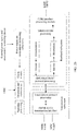
- FIG. 3 shows a reference signal configuration method provided in an embodiment of the present invention. As shown in FIG. 3 , the method includes the following steps.
- a base station generates resource configuration information, where the resource configuration information is used to indicate a resource unit occupied by a reference signal of a first terminal, a time-frequency resource on which the resource unit is located includes a plurality of contiguous symbols in time domain and a plurality of contiguous subcarriers in frequency domain, the reference signal is carried in at least one of the plurality of symbols, the reference signal is carried in a plurality of subcarrier groups on the symbol that carries the reference signal, each of the plurality of subcarrier groups includes a plurality of subcarriers whose frequencies are contiguous, adjacent subcarrier groups are spaced by a preset quantity of subcarriers, the reference signal occupies one subcarrier in each subcarrier group, and the first terminal uses a first waveform.
- the resource unit includes at least one of the plurality of symbols in time domain and one subcarrier in each of the plurality of subcarrier groups in frequency domain.
- the foregoing time-frequency resource may be similar to an RB or an RB pair in LTE.
- the first waveform in this embodiment of the present invention is a discrete Fourier transform-spread-orthogonal frequency division multiplexing DFT-S-OFDM waveform.
- the base station In S101, the base station generates the resource configuration information.
- the resource configuration information is used to indicate the resource unit occupied by the reference signal of the first terminal.
- FIG. 4 is an example schematic diagram of a distribution pattern 100 of resources used by the reference signal of the first terminal based on an indication of the base station.
- a minimum resource granularity may be one OFDM symbol, or may be one SC-FDMA symbol during uplink transmission (which are collectively referred to as the OFDM symbol below).
- a minimum resource granularity is one subcarrier.
- One time-frequency resource unit, that is, one resource element (Resource Element, RE) includes one OFDM symbol and one subcarrier. Resource mapping is performed at a physical layer on an RE basis. As shown in FIG.
- resource elements (Resource Element, RE) occupied by the reference signal R corresponding to an antenna port 1 are distributed in two resource blocks 104 and 106 included in a resource block (Resource Block) pair 102.
- the resource block pair 102 includes a plurality of contiguous symbols in time domain and a plurality of contiguous subcarriers in frequency domain.
- locations of resource elements that carry the reference signal are fixed. Based on the reference signal carried in the resource elements, channel estimation can be performed on the entire resource block 102 with reference to a specific interpolation method. It can be learned that the resource unit includes at least one of the plurality of symbols in time domain and one subcarrier in each of the plurality of subcarrier groups in frequency domain.
- the foregoing time-frequency resource may be similar to the RB or the RB pair in LTE.
- This embodiment of the present invention provides a resource unit, and the resource unit may be used as a basic unit for resource allocation when scheduling is performed for a user, or may be a unit used to describe a manner of arranging a plurality of reference signals. With reference to FIG. 4 , the following describes the resource unit provided in this embodiment of the present invention.
- FIG. 4 is a schematic structural diagram of a resource unit 100 according to this embodiment of the present invention.
- the resource unit (Resource Unit) 100 occupies a plurality of contiguous subcarriers in frequency domain and a plurality of contiguous symbols (OFDM symbols) in time domain.
- a minimum unit of the resource unit is a resource element (Resource Element, RE), and each resource element occupies one subcarrier in frequency domain and one symbol in time domain.
- the resource unit 100 includes a plurality of REs.
- the reference signal of the first terminal is carried in at least one of the plurality of symbols.
- the reference signal is carried in the plurality of subcarrier groups, such as a first subcarrier group, a second subcarrier group, and a third subcarrier group in FIG. 5 .
- subcarrier groups such as a first subcarrier group, a second subcarrier group, and a third subcarrier group in FIG. 5 .
- a quantity of subcarrier groups may be one or more, and is not limited to the three groups listed herein.
- Each of the plurality of subcarrier groups includes a plurality of contiguous subcarriers.
- the first subcarrier group includes a first subcarrier and a second subcarrier.
- that one subcarrier group may include two subcarriers is only used as an example. It may be understood that, in an actual use process, one subcarrier group may alternatively include three or more subcarriers.
- Subcarriers of a preset quantity are spaced between the adjacent subcarrier groups.
- the reference signal occupies one subcarrier in each subcarrier group. If one subcarrier group includes two subcarriers, the reference signal occupies half of resources in the subcarrier group.
- the reference signal occupies one-third or less of the resources in the subcarrier group.
- the reference signal may also occupy two or more subcarriers when the subcarrier group includes three or more subcarriers, provided that the subcarriers occupied by the reference signal are only some of the subcarriers in the subcarrier group and that the reference signal can maintain a low peak-to-average power ratio (PAPR-Peak to Average Power Ratio, PAPR).
- PAPR-Peak to Average Power Ratio PAPR
- Step S102 After the base station determines the resource unit occupied by the reference signal of the first terminal, the base station sends the resource configuration information to the terminal.
- the base station may send the resource configuration information to the terminal by using downlink control information (Downlink control information, DCI).
- DCI Downlink control information
- step S103 and step S104 the first terminal receives and saves the resource configuration information sent by the base station. Then, in step S104 and step S105, the first terminal generates the reference signal, and a first base station sends the reference signal to the base station based on the resource unit indicated by the saved resource configuration information.
- step S105 in this embodiment of the present invention the method provided in this embodiment of the present invention further includes the following step.
- Step S106 The base station receives the reference signal sent by the first terminal.
- one terminal can use only one waveform, that is, the DFT-S-OFDM waveform or a CP-OFDM waveform.
- one terminal can use the DFT-S-OFDM waveform, and the other terminal can use the CP-OFDM waveform.
- MU between a first terminal that uses the DFT-S-OFDM waveform and a second terminal that uses the CP-OFDM waveform at the same time can be implemented.
- DFT-S-OFDM is used for user equipment at an edge of a cell and CP-OFDM is used for user equipment at a center of a cell
- CP-OFDM can use a time-frequency resource occupied by DFT-S-OFDM, thereby improving performance of CP-OFDM.
- the subcarrier occupied by the reference signal in each subcarrier group is a subcarrier with a highest frequency or a lowest frequency.
- the reference signal may be determined, based on a parameter such as channel quality, that the reference signal is placed on the subcarrier with the highest frequency or the subcarrier with the lowest frequency in each subcarrier group.
- the reference signal of the first terminal is multiplexed on the subcarrier by using an orthogonal code of the reference signal
- a reference signal of the second terminal is multiplexed on the subcarrier by using an orthogonal code of the reference signal; that is, the reference signal of each terminal is multiplexed on the subcarrier in the subcarrier group by using an orthogonal code of the terminal.
- the orthogonal code may be an orthogonal cover code (Orthogonal Cover Code, OCC).
- each subcarrier group includes two subcarriers
- the first waveform is the DFT-S-OFDM waveform
- the reference signal of the second terminal that uses the CP-OFDM waveform is carried in a subcarrier group that carries a DMRS to describe specific content of sending the resource configuration information by the base station to the terminal, and distribution of the reference signals of the first terminal that uses the DFT-S-OFDM waveform and the reference signals of the second terminal that uses the CP-OFDM waveform on a pattern.
- the resource configuration information in this embodiment of the present invention includes a first identifier of each of the plurality of subcarrier groups that carry the reference signal, and a second identifier of a subcarrier occupied by the reference signal in the subcarrier group that carries the reference signal.
- the configuration information may include only an identifier of the subcarrier group in which the reference signal is located.
- the first identifier is used to uniquely identify the subcarrier group
- the second identifier is used to uniquely identify the subcarrier.
- the first identifier and the second identifier may be numbers.
- each subcarrier group may be numbered, for example, the first subcarrier group is numbered 10, the second subcarrier group is numbered 20, and so on. Details are not described herein in this embodiment of the present invention. It may be understood that the foregoing example only illustrates that the identifier of each subcarrier group is a number and may be set based on a requirement during an actual use process. For another example, a number of the first subcarrier in the first subcarrier group may be 101.
- the configuration indication information sent by the base station to the second terminal that uses the CP-OFDM waveform is only used to indicate a specific subcarrier group that carries the reference signal.
- the second terminal that uses the CP-OFDM waveform After receiving the configuration indication information, the second terminal that uses the CP-OFDM waveform sends the reference signal in the subcarrier group indicated by the configuration indication information. That is, as shown in FIG. 5 , reference signals X1, X2, X3, X4, X5, and X6 of the terminal that uses the CP-OFDM waveform are respectively configured on each subcarrier in the first subcarrier group, the second subcarrier group, and the third subcarrier group.
- the terminal that uses the first waveform such as the DFT-S-OFDM waveform includes reference signals S1, S2, and S3.
- the resource configuration information is used to indicate that the reference signal S1 is carried in the first subcarrier group, and the reference signal S1 occupies the first subcarrier in the first subcarrier group, that the reference signal S2 is carried in the second subcarrier group, and the reference signal S2 occupies a first subcarrier in the second subcarrier group, and that the reference signal S3 is carried in the third subcarrier group, and the reference signal S3 occupies a first subcarrier in the third subcarrier group.
- the first terminal After receiving the resource configuration information, the first terminal maps the reference signal S1 onto the first subcarrier in the first subcarrier group, maps the reference signal S2 onto the first subcarrier in the second subcarrier group, and maps the reference signal S3 onto the first subcarrier in the third subcarrier group.
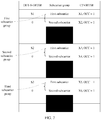
- the resource configuration information in this embodiment of the present invention includes the first identifier of each of the plurality of subcarrier groups that carry the reference signals, and an OCC codebook sequence is corresponding to the reference signal.
- the OCC codebook sequence includes a plurality of indicators, and each of the plurality of indicators is corresponding to one subcarrier in the subcarrier group that carries the reference signal.
- the OCC codebook sequence corresponding to one reference signal is used to instruct the first terminal to configure the reference signal on a specific subcarrier in the subcarrier group that carries the reference signal. That is, the OCC codebook sequence corresponding to one reference signal is used to indicate a specific location of the reference signal in the subcarrier group.
- a quantity of indicators in the OCC codebook sequence may be determined based on a quantity of subcarriers in the subcarrier group that carries the reference signal corresponding to the OCC codebook.
- the OCC codebook sequence in this embodiment of the present invention includes a first indicator and a second indicator, for example, the first indicator is “1" and the second indicator is "0".
- the first indicator in the OCC codebook sequence is used to instruct the first terminal to map the reference signal onto a subcarrier corresponding to the first indicator
- the second indicator in the OCC codebook sequence is used to instruct the first terminal not to map the reference signal onto a subcarrier corresponding to the second indicator
- the resource configuration information is used to indicate that the reference signal S1, the reference signal S2, and the reference signal S3 are respectively carried in the first subcarrier group, the second subcarrier group, and the third subcarrier group
- the codebooks corresponding to the reference signal S1, the reference signal S2, and the reference signal S3 are [1, 0].
- the first terminal maps the reference signal S1 onto the first subcarrier; or if an indicator corresponding to the second subcarrier in the first subcarrier group is 0, the first terminal does not map the reference signal S2 onto the second subcarrier. If the first subcarrier in the second subcarrier group is corresponding to the indicator 1, the first terminal maps the reference signal S2 onto the first subcarrier in the second subcarrier group; or if a second subcarrier in the second subcarrier group is corresponding to the indicator 0, the terminal does not map the reference signal S2 onto the second subcarrier in the second subcarrier group.
- the first terminal maps the reference signal S3 onto the first subcarrier in the third subcarrier group; or if a second subcarrier in the third subcarrier group is corresponding to the indicator 0, the first terminal does not map the reference signal S3 onto the second subcarrier in the third subcarrier group.
- distribution of the reference signals on the resource unit may be shown in FIG. 6 .
- the first indicator in the OCC codebook sequence is used to instruct the first terminal to generate a reference signal on a subcarrier in the subcarrier group that carries the reference signal
- the second indicator in the OCC codebook sequence is used to instruct the first terminal not to generate a reference signal on a subcarrier in the subcarrier group that carries the reference signal
- the first terminal generates a reference signal on one subcarrier in the subcarrier group that carries the reference signal, and does not generate a reference signal on another subcarrier in the subcarrier group that carries the reference signal; that is, a sequence of the reference signals generated on the subcarrier group that carries the reference signal is [S1, 0].
- the following uses the reference signal S1, the reference signal S2, and the reference signal S3 as an example for detailed description: If the first terminal determines that the codebook corresponding to the reference signal is [S1, 0], a sequence of the reference signals generated on the subcarrier group that carries the reference signal S1, the reference signal S2, and the reference signal S3 is [S1, 0, S2, 0, S3, 0...]. The first terminal configures, based on the sequence of the generated reference signals, the reference signals on the subcarriers in the subcarrier group that carries the reference signal, as shown in FIG. 7 .
- the codebook corresponding to the reference signal is [0, 1], that is, if the codebooks respectively corresponding to the reference signal S1, the reference signal S2, and the reference signal S3 are [0, 1], the sequence of the reference signals generated by the first terminal is [0, S1, 0, S2, 0, S3...].
- the first terminal places, based on the sequence [0, S1, 0, S2, 0, S3...] corresponding to the foregoing reference signals, the reference signals on the subcarriers that carry the reference signals.
- each indicator in the OCC codebook sequence is used to instruct the first terminal to map a result obtained by multiplying the reference signal by the indicator onto a subcarrier in the subcarrier group that carries the reference signal.
- the first terminal multiplies each reference signal in the reference signal sequence by an indicator in an OCC codebook sequence, and maps a result obtained by multiplying each reference signal by the indicator in the codebook sequence corresponding to the reference signal onto a subcarrier, as shown in FIG. 8a .
- the reference signal S1 is multiplied by the indicator 1 in the OCC codebook, so that the reference signal S1 is carried in the first subcarrier in the first subcarrier group.
- the reference signal S1 is multiplied by the indicator 0 in the OCC codebook, so that the reference signal S1 is not carried in the second subcarrier in the first subcarrier group.
- the reference signal S2 is multiplied by the indicator 1 in the OCC codebook, so that the reference signal S2 is carried in the first subcarrier in the second subcarrier group.
- the reference signal S2 is multiplied by the indicator 0 in the OCC codebook, so that the reference signal S2 is not carried in the second subcarrier in the second subcarrier group.
- the reference signal S3 is multiplied by the indicator 1 in the OCC codebook, so that the reference signal S3 is carried in the first subcarrier in the third subcarrier group.
- the reference signal S3 is multiplied by the indicator 0 in the OCC codebook, so that the reference signal S3 is not carried in the second subcarrier in the third subcarrier group.
- the reference signal S1 and the reference signal S2 are carried in the first subcarrier group
- the reference signal S3 and the reference signal S4 are carried in the second subcarrier group
- the reference signal S5 and the reference signal S6 are carried in the third subcarrier group.
- the first terminal After generating the reference signal sequence [S1, S2, S3, S4, S5, S6, ...], the first terminal multiplies each reference signal in the reference signal sequence [S1, S2, S3, S4, S5, S6, ...] by an indicator in an OCC codebook sequence, and maps a result obtained by multiplying each reference signal by the indicator in the codebook sequence corresponding to the reference signal onto a subcarrier.
- the reference signal S1 is multiplied by the indicator 1 in the OCC codebook, so that the reference signal S1 is carried in the first subcarrier in the first subcarrier group.
- the reference signal S2 is multiplied by the indicator 0 in the OCC codebook, so that the reference signal S2 is not carried in the second subcarrier in the first subcarrier group.
- the reference signal S3 is multiplied by the indicator 1 in the OCC codebook, so that the reference signal S3 is carried in the first subcarrier in the second subcarrier group.
- the reference signal S4 is multiplied by the indicator 0 in the OCC codebook, so that the reference signal S4 is not carried in the second subcarrier in the second subcarrier group.
- the reference signal S5 is multiplied by the indicator 1 in the OCC codebook, so that the reference signal S5 is carried in the first subcarrier in the third subcarrier group.
- the reference signal S6 is multiplied by the indicator 0 in the OCC codebook, so that the reference signal S6 is not carried in the second subcarrier in the third subcarrier group.
- the resource configuration indication information includes the first identifier of each of the plurality of subcarrier groups that carry the reference signals, and the OCC codebook sequences corresponding to the reference signals, where the first terminal and the second terminal use different OCC codebooks.
- an OCC codebook used by the first terminal is [1, 0]
- an OCC codebook used by the second terminal is [1, 1].
- the sequence of the reference signals generated by the first terminal is [S1, S2, S3, S4, S5, S6...]
- a sequence of reference signals generated by the first terminal is [X1, X2, X3, X4, X5, X6...].
- the reference signal S1 is carried in the first subcarrier in the first subcarrier group, and after the reference signal S2 is multiplied by the indicator 0 in the OCC codebook, the reference signal S2 is not carried in the second subcarrier in the first subcarrier group.
- the reference signal X1 is carried in the first subcarrier in the first subcarrier group, and after a reference signal X2 is multiplied by the indicator 1 in the OCC codebook, the reference signal X2 is carried in the first subcarrier in the first subcarrier group.
- the reference signal S1 is carried in the first subcarrier in the first subcarrier group
- the reference signal S3 is carried in the first subcarrier in the second subcarrier group
- the reference signal S5 is carried in the first subcarrier in the third subcarrier group.
- the reference signal X1 is carried in the first subcarrier in the first subcarrier group
- the reference signal X2 is carried in the second subcarrier in the first subcarrier group
- the reference signal X3 is carried in the first subcarrier in the second subcarrier group
- the reference signal X4 is carried in the second subcarrier in the second subcarrier group
- the reference signal X5 is carried in the first subcarrier in the third subcarrier group
- the reference signal X6 is carried in the second subcarrier in the third subcarrier group.
- the base station and the terminal include hardware structures and/or software modules for performing corresponding functions.
- a person of ordinary skill in the art should easily be aware that, in combination with the examples described in the embodiments disclosed in this specification, network element, algorithms steps may be implemented by hardware or a combination of hardware and computer software. Whether a function is performed by hardware or hardware driven by computer software depends on particular applications and design constraints of the technical solutions. A person skilled in the art may use different methods to implement the described functions for each particular application, but it should not be considered that the implementation goes beyond the scope of this application.
- function module division may be performed on the base station and the terminal based on the foregoing method example.
- each function module may be obtained through division based on a corresponding function, or two or more functions may be integrated into one processing module.
- the integrated module may be implemented in a form of hardware, or may be implemented in a form of a software function module.
- module division is used as an example, and is merely a logical function division. In actual implementation, another division manner may be used.
- FIG. 10 is a possible schematic structural diagram of the base station in the foregoing embodiment.
- the base station 300 includes a generation unit 301 and a sending unit 302.
- the generation unit 301 is configured to perform step S101 in the foregoing embodiment; and the sending unit 302 is configured to perform step S102 in the foregoing embodiment. All related content of the steps in the foregoing method embodiment may be cited in function descriptions of corresponding function modules, and details are not described herein again.
- the generation unit 301 may be a processor of the base station
- the sending unit 302 may be a transmitter
- the transmitter may be integrated with a receiver to form a transceiver.
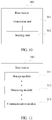
- FIG. 11 is a possible schematic diagram of a logical structure of a base station 310 in the foregoing embodiment.
- the base station 310 includes a processing module 312 and a communications module 313.
- the processing module 312 is configured to control and manage an action of an application function, for example, the processing module 312 is configured to perform steps S101 and S102 in the foregoing embodiment, and/or is configured to perform another process of the technology described in this specification.
- the communications module 313 is configured to communicate with a terminal.
- the base station 310 may further include a storage module 311, configured to store program code and data of the base station.
- the processing module 312 may be a processor or a controller, for example, may be a central processing unit, a general purpose processor, a digital signal processor, an application-specific integrated circuit, a field programmable gate array or another programmable logic device, a transistor logical device, a hardware component, or any combination thereof.
- the processing module 312 may implement or execute various example logical blocks, modules, and circuits described with reference to content disclosed in the present invention.
- the processor may be a combination for implementing a computing function, for example, a combination of one or more microprocessors, or a combination of a digital signal processor and a microprocessor.
- the communications module 313 may be a transceiver, a transceiver circuit, or the like.
- the storage module 311 may be a memory.
- the base station in this embodiment of the present invention may be a device shown in FIG. 12 .
- FIG. 12 shows an example structure of a base station.
- the base station 320 includes a processor 322, a transceiver 323, a memory 321, and a bus 324.
- the transceiver 323, the processor 322, and the memory 321 are connected to each other by using the bus 324.
- the bus 324 may be a peripheral component interconnect (peripheral component interconnect, PCI) bus, an extended industry standard architecture (extended industry standard architecture, EISA) bus, or the like.
- PCI peripheral component interconnect
- EISA extended industry standard architecture
- the bus may be classified into an address bus, a data bus, a control bus, and the like. For ease of illustration, only one thick line is used in FIG. 12 to represent the bus, but it does not indicate that there is only one bus or only one type of bus.
- FIG. 13 is a possible schematic structural diagram of a terminal in the foregoing embodiment.
- the terminal 400 includes a generation unit 401, a receiving unit 402, and a sending unit 403.
- the generation unit 401 is configured to perform step S103 in the foregoing embodiment;
- the receiving unit 402 is configured to perform step S104 in the foregoing embodiment;
- the sending unit 403 is configured to perform step S105 in the foregoing embodiment. All related content of the steps in the foregoing method embodiment may be cited in function descriptions of corresponding function modules, and details are not described herein again.
- the generation unit 401 may be a processor of the base station
- the receiving unit 402 may be a receiver
- the sending unit 403 may be a transmitter
- the receiver may be integrated with the transmitter to form a transceiver of the terminal.
- FIG. 14 is a possible schematic diagram of a logical structure of a terminal 410 in the foregoing embodiment.
- the terminal 410 includes a processing module 412 and a communications module 413.
- the processing module 412 is configured to control and manage an action of the terminal, for example, the processing module 412 is configured to perform steps S103, S104 and S105 in the foregoing embodiment, and/or is configured to perform another process of the technology described in this specification.
- the communications module 413 is configured to communicate with a base station.
- the terminal 410 may further include a storage module 411, configured to store program code and data of the terminal.
- the processing module 412 may be a processor or a controller, for example, may be a central processing unit, a general purpose processor, a digital signal processor, an application-specific integrated circuit, a field programmable gate array or another programmable logic device, a transistor logic device, a hardware component, or any combination thereof.
- the processing module 412 may implement or execute various example logical blocks, modules, and circuits described with reference to content disclosed in the present invention.
- the processor may be a combination for implementing a computing function, for example, a combination of one or more microprocessors, or a combination of a digital signal processor and a microprocessor.
- the communications module 413 may be a transceiver, a transceiver circuit, or the like.
- the storage module 411 may be a memory.
- the terminal in this embodiment of the present invention may be a device shown in FIG. 15 .
- FIG. 15 shows an example structure of a terminal, where the terminal 420 includes a processor 422, a transceiver 423, a memory 421, and a bus 424.
- the transceiver 423, the processor 422, and the memory 421 are interconnected by using the bus 424.
- the bus 424 may be a PCI bus, an EISA bus, or the like.
- the bus may be classified into an address bus, a data bus, a control bus, and the like. For ease of illustration, only one thick line is used in FIG. 15 to represent the bus, but it does not indicate that there is only one bus or only one type of bus.
- an embodiment of the present invention provides a computer readable storage medium, where the computer readable storage medium stores an instruction, and when the computer readable storage medium runs on a computer, the base station is enabled to perform steps S101 and S102 in the foregoing embodiment.
- an embodiment of the present invention provides a computer readable storage medium, where the computer readable storage medium stores an instruction, and when the computer readable storage medium runs on a computer, the terminal is enabled to perform steps S103 to S105 in the foregoing embodiment.
- All or some of the foregoing embodiments may be implemented in a form of software, hardware, firmware, or any combination thereof.
- a software program is used to implement the embodiments, the embodiments may be implemented completely or partially in a form of a computer program product.
- the computer program product includes one or more computer instructions. When the computer program instructions are loaded and executed on the computer, the procedure or functions described according to the embodiments of the present invention are all or partially generated.
- the computer may be a general purpose computer, a dedicated computer, a computer network, or other programmable apparatuses.
- the computer instructions may be stored in a computer readable storage medium or may be transmitted from a computer readable storage medium to another computer readable storage medium.
- the computer instructions may be transmitted from a website, computer, server, or data center to another website, computer, server, or data center in a wired (for example, a coaxial cable, an optical fiber, or a digital subscriber line DSL) or wireless (for example, infrared, radio, and microwave, or the like) manner.
- the computer readable storage medium may be any usable medium accessible by a computer, or a data storage device, such as a server or a data center, integrating one or more usable media.
- the usable medium may be a magnetic medium (for example, a floppy disk, a hard disk, or a magnetic tape), an optical medium (for example, a DVD), a semiconductor medium (for example, a solid state disk (Solid State Disk, SSD)), or the like.
- a magnetic medium for example, a floppy disk, a hard disk, or a magnetic tape
- an optical medium for example, a DVD
- a semiconductor medium for example, a solid state disk (Solid State Disk, SSD)
- the disclosed system, apparatus, and method may be implemented in other manners.
- the described apparatus embodiment is merely an example.
- the module or unit division is merely logical function division and may be other division in actual implementation.
- a plurality of units or components may be combined or integrated into another system, or some features may be ignored or not performed.
- the displayed or discussed mutual couplings or direct couplings or communication connections may be implemented by using some interfaces.
- the indirect couplings or communication connections between the apparatuses or units may be implemented in electronic, mechanical, or other forms.
- the units described as separate parts may or may not be physically separate, and parts displayed as units may or may not be physical units, may be located in one position, or may be distributed on a plurality of network units. Some or all of the units may be selected based on actual requirements to achieve the objectives of the solutions of the embodiments.
- function units in the embodiments of this application may be integrated into one processing unit, or each of the units may exist alone physically, or two or more units may be integrated into one unit.
- the integrated unit may be implemented in a form of hardware, or may be implemented in a form of a software function unit.
- the integrated unit When the integrated unit is implemented in the form of a software function unit and sold or used as an independent product, the integrated unit may be stored in a computer readable storage medium.
- the computer software product is stored in a storage medium and includes several instructions for instructing a computer device (which may be a personal computer, a server, or a network device) or a processor to perform all or some of the steps of the methods described in the embodiments of this application.
- the foregoing storage medium includes: any medium that can store program code, such as a flash memory, a removable hard disk, a read-only memory, a random access memory, a magnetic disk, or an optical disc.
Landscapes
- Engineering & Computer Science (AREA)
- Signal Processing (AREA)
- Computer Networks & Wireless Communication (AREA)
- Mobile Radio Communication Systems (AREA)
Applications Claiming Priority (2)
| Application Number | Priority Date | Filing Date | Title |
|---|---|---|---|
| CN201710061810.1A CN108365935B (zh) | 2017-01-26 | 2017-01-26 | 一种参考信号配置方法、基站和终端 |
| PCT/CN2017/119087 WO2018137460A1 (fr) | 2017-01-26 | 2017-12-27 | Procédé de configuration de signal de référence, station de base et terminal |
Publications (3)
| Publication Number | Publication Date |
|---|---|
| EP3557847A1 true EP3557847A1 (fr) | 2019-10-23 |
| EP3557847A4 EP3557847A4 (fr) | 2020-01-01 |
| EP3557847B1 EP3557847B1 (fr) | 2020-12-23 |
Family
ID=62978061
Family Applications (1)
| Application Number | Title | Priority Date | Filing Date |
|---|---|---|---|
| EP17894029.2A Active EP3557847B1 (fr) | 2017-01-26 | 2017-12-27 | Procédé de configuration de signal de référence, station de base et terminal |
Country Status (4)
| Country | Link |
|---|---|
| US (1) | US20190349164A1 (fr) |
| EP (1) | EP3557847B1 (fr) |
| CN (1) | CN108365935B (fr) |
| WO (1) | WO2018137460A1 (fr) |
Cited By (1)
| Publication number | Priority date | Publication date | Assignee | Title |
|---|---|---|---|---|
| CN111869156A (zh) * | 2020-06-16 | 2020-10-30 | 北京小米移动软件有限公司 | 参考信号资源的配置方法、装置、通信设备及存储介质 |
Families Citing this family (8)
| Publication number | Priority date | Publication date | Assignee | Title |
|---|---|---|---|---|
| CN109802792B (zh) * | 2017-11-17 | 2021-09-21 | 华为技术有限公司 | 接收参考信号的方法和发送参考信号的方法 |
| WO2019140562A1 (fr) * | 2018-01-17 | 2019-07-25 | Qualcomm Incorporated | Techniques et appareils destinés à un signal de référence de démodulation et rotation de phase destinée à une attribution de blocs de ressource sous-physique au moyen d'une modulation à deux tonalités |
| CN116260562B (zh) * | 2018-12-05 | 2025-08-01 | 中兴通讯股份有限公司 | 用于使用离散频谱的技术 |
| CN111435928B (zh) * | 2019-03-19 | 2021-12-21 | 维沃移动通信有限公司 | 传输方法及终端 |
| CN111294188B (zh) * | 2019-07-16 | 2021-07-27 | 北京紫光展锐通信技术有限公司 | 参考信号信息的确定方法及装置、存储介质、终端 |
| CN113966000B (zh) * | 2020-07-20 | 2025-04-04 | 华为技术有限公司 | 用于波束训练的方法和装置 |
| CN112134676B (zh) * | 2020-09-28 | 2025-11-04 | 中兴通讯股份有限公司 | 参考信号传输方法、装置、通信节点及存储介质 |
| US12213104B1 (en) * | 2021-07-09 | 2025-01-28 | T-Mobile Usa, Inc. | Selecting data throughput using waveform switching |
Family Cites Families (5)
| Publication number | Priority date | Publication date | Assignee | Title |
|---|---|---|---|---|
| CN101222268B (zh) * | 2007-01-08 | 2011-11-30 | 中兴通讯股份有限公司 | 连续频分多址系统跳频发射机、接收机装置及其跳频方法 |
| BRPI0813126B1 (pt) * | 2007-06-19 | 2020-02-04 | Panasonic Corp | estação base, método para transmitir dados, estação móvel e método para receber dados |
| CN101778068B (zh) * | 2009-12-25 | 2014-01-01 | 中兴通讯股份有限公司 | 定位参考信号频域位置确定方法及装置 |
| CN102469059B (zh) * | 2010-11-15 | 2015-10-28 | 中兴通讯股份有限公司 | 解调参考信号承载方法及装置 |
| WO2014190472A1 (fr) * | 2013-05-27 | 2014-12-04 | 华为技术有限公司 | Procédé et dispositif de soumission d'informations de mesure de qualité de signal |
-
2017
- 2017-01-26 CN CN201710061810.1A patent/CN108365935B/zh active Active
- 2017-12-27 WO PCT/CN2017/119087 patent/WO2018137460A1/fr not_active Ceased
- 2017-12-27 EP EP17894029.2A patent/EP3557847B1/fr active Active
-
2019
- 2019-07-25 US US16/522,324 patent/US20190349164A1/en not_active Abandoned
Cited By (2)
| Publication number | Priority date | Publication date | Assignee | Title |
|---|---|---|---|---|
| CN111869156A (zh) * | 2020-06-16 | 2020-10-30 | 北京小米移动软件有限公司 | 参考信号资源的配置方法、装置、通信设备及存储介质 |
| CN111869156B (zh) * | 2020-06-16 | 2023-10-03 | 北京小米移动软件有限公司 | 参考信号资源的配置方法、装置、通信设备及存储介质 |
Also Published As
| Publication number | Publication date |
|---|---|
| CN108365935A (zh) | 2018-08-03 |
| CN108365935B (zh) | 2020-01-03 |
| US20190349164A1 (en) | 2019-11-14 |
| EP3557847A4 (fr) | 2020-01-01 |
| EP3557847B1 (fr) | 2020-12-23 |
| WO2018137460A1 (fr) | 2018-08-02 |
Similar Documents
| Publication | Publication Date | Title |
|---|---|---|
| EP3557847B1 (fr) | Procédé de configuration de signal de référence, station de base et terminal | |
| CN108768599B (zh) | 上行信号的发送、接收方法及装置、存储介质、电子设备 | |
| US12184579B2 (en) | Method and apparatus for transmitting DMRS | |
| CN109495231B (zh) | 传输信号的方法和设备 | |
| EP2875690B1 (fr) | Noeud de réseau et procédé dans celui-ci pour planifier une transmission de données en liaison descendante à un ue | |
| EP3217711B1 (fr) | Dispositif de station de base, dispositif de terminal et procédé de communication | |
| CN111726877B (zh) | 数据传输方法、终端和基站 | |
| EP3740008B1 (fr) | Procédé de détermination d'emplacement de canal de commande, dispositif et support de stockage lisible par processeur | |
| EP3565167B1 (fr) | Procédé et appareil de transmission d'informations | |
| JP2020504484A (ja) | 基準信号の伝送方法及び通信装置 | |
| WO2017092697A1 (fr) | Procédé et dispositif de traitement de signal de communication dans un système de communication | |
| WO2019158092A1 (fr) | Procédé d'apprentissage du nombre d'unités de ressource dans un processus de communication et dispositif associé | |
| WO2016122763A1 (fr) | Rapport apériodique d'informations d'état de canal (csi) pour agrégation de porteuses | |
| EP4487635A1 (fr) | Amélioration de la capacité d'un signal de référence de sondage | |
| US20190305902A1 (en) | Reference signal transmission method and apparatus | |
| US11005626B2 (en) | Parameter configuration method and related products | |
| US11962521B2 (en) | Radio communication apparatus, method, program, non-transitory computer readable recording medium, and system | |
| CN120457663A (zh) | 控制资源集的配置 |
Legal Events
| Date | Code | Title | Description |
|---|---|---|---|
| STAA | Information on the status of an ep patent application or granted ep patent |
Free format text: STATUS: THE INTERNATIONAL PUBLICATION HAS BEEN MADE |
|
| PUAI | Public reference made under article 153(3) epc to a published international application that has entered the european phase |
Free format text: ORIGINAL CODE: 0009012 |
|
| STAA | Information on the status of an ep patent application or granted ep patent |
Free format text: STATUS: REQUEST FOR EXAMINATION WAS MADE |
|
| 17P | Request for examination filed |
Effective date: 20190719 |
|
| AK | Designated contracting states |
Kind code of ref document: A1 Designated state(s): AL AT BE BG CH CY CZ DE DK EE ES FI FR GB GR HR HU IE IS IT LI LT LU LV MC MK MT NL NO PL PT RO RS SE SI SK SM TR |
|
| AX | Request for extension of the european patent |
Extension state: BA ME |
|
| A4 | Supplementary search report drawn up and despatched |
Effective date: 20191203 |
|
| RIC1 | Information provided on ipc code assigned before grant |
Ipc: H04L 5/00 20060101ALI20191127BHEP Ipc: H04L 29/08 20060101AFI20191127BHEP Ipc: H04L 27/26 20060101ALI20191127BHEP |
|
| DAV | Request for validation of the european patent (deleted) | ||
| DAX | Request for extension of the european patent (deleted) | ||
| GRAP | Despatch of communication of intention to grant a patent |
Free format text: ORIGINAL CODE: EPIDOSNIGR1 |
|
| STAA | Information on the status of an ep patent application or granted ep patent |
Free format text: STATUS: GRANT OF PATENT IS INTENDED |
|
| INTG | Intention to grant announced |
Effective date: 20200727 |
|
| GRAS | Grant fee paid |
Free format text: ORIGINAL CODE: EPIDOSNIGR3 |
|
| GRAA | (expected) grant |
Free format text: ORIGINAL CODE: 0009210 |
|
| STAA | Information on the status of an ep patent application or granted ep patent |
Free format text: STATUS: THE PATENT HAS BEEN GRANTED |
|
| AK | Designated contracting states |
Kind code of ref document: B1 Designated state(s): AL AT BE BG CH CY CZ DE DK EE ES FI FR GB GR HR HU IE IS IT LI LT LU LV MC MK MT NL NO PL PT RO RS SE SI SK SM TR |
|
| REG | Reference to a national code |
Ref country code: GB Ref legal event code: FG4D |
|
| REG | Reference to a national code |
Ref country code: DE Ref legal event code: R096 Ref document number: 602017030262 Country of ref document: DE |
|
| REG | Reference to a national code |
Ref country code: AT Ref legal event code: REF Ref document number: 1348813 Country of ref document: AT Kind code of ref document: T Effective date: 20210115 |
|
| REG | Reference to a national code |
Ref country code: IE Ref legal event code: FG4D |
|
| PG25 | Lapsed in a contracting state [announced via postgrant information from national office to epo] |
Ref country code: RS Free format text: LAPSE BECAUSE OF FAILURE TO SUBMIT A TRANSLATION OF THE DESCRIPTION OR TO PAY THE FEE WITHIN THE PRESCRIBED TIME-LIMIT Effective date: 20201223 Ref country code: FI Free format text: LAPSE BECAUSE OF FAILURE TO SUBMIT A TRANSLATION OF THE DESCRIPTION OR TO PAY THE FEE WITHIN THE PRESCRIBED TIME-LIMIT Effective date: 20201223 Ref country code: NO Free format text: LAPSE BECAUSE OF FAILURE TO SUBMIT A TRANSLATION OF THE DESCRIPTION OR TO PAY THE FEE WITHIN THE PRESCRIBED TIME-LIMIT Effective date: 20210323 Ref country code: GR Free format text: LAPSE BECAUSE OF FAILURE TO SUBMIT A TRANSLATION OF THE DESCRIPTION OR TO PAY THE FEE WITHIN THE PRESCRIBED TIME-LIMIT Effective date: 20210324 |
|
| REG | Reference to a national code |
Ref country code: AT Ref legal event code: MK05 Ref document number: 1348813 Country of ref document: AT Kind code of ref document: T Effective date: 20201223 |
|
| REG | Reference to a national code |
Ref country code: NL Ref legal event code: MP Effective date: 20201223 |
|
| PG25 | Lapsed in a contracting state [announced via postgrant information from national office to epo] |
Ref country code: LV Free format text: LAPSE BECAUSE OF FAILURE TO SUBMIT A TRANSLATION OF THE DESCRIPTION OR TO PAY THE FEE WITHIN THE PRESCRIBED TIME-LIMIT Effective date: 20201223 Ref country code: SE Free format text: LAPSE BECAUSE OF FAILURE TO SUBMIT A TRANSLATION OF THE DESCRIPTION OR TO PAY THE FEE WITHIN THE PRESCRIBED TIME-LIMIT Effective date: 20201223 Ref country code: BG Free format text: LAPSE BECAUSE OF FAILURE TO SUBMIT A TRANSLATION OF THE DESCRIPTION OR TO PAY THE FEE WITHIN THE PRESCRIBED TIME-LIMIT Effective date: 20210323 |
|
| PG25 | Lapsed in a contracting state [announced via postgrant information from national office to epo] |
Ref country code: NL Free format text: LAPSE BECAUSE OF FAILURE TO SUBMIT A TRANSLATION OF THE DESCRIPTION OR TO PAY THE FEE WITHIN THE PRESCRIBED TIME-LIMIT Effective date: 20201223 Ref country code: HR Free format text: LAPSE BECAUSE OF FAILURE TO SUBMIT A TRANSLATION OF THE DESCRIPTION OR TO PAY THE FEE WITHIN THE PRESCRIBED TIME-LIMIT Effective date: 20201223 |
|
| REG | Reference to a national code |
Ref country code: DE Ref legal event code: R119 Ref document number: 602017030262 Country of ref document: DE |
|
| REG | Reference to a national code |
Ref country code: LT Ref legal event code: MG9D |
|
| PG25 | Lapsed in a contracting state [announced via postgrant information from national office to epo] |
Ref country code: SK Free format text: LAPSE BECAUSE OF FAILURE TO SUBMIT A TRANSLATION OF THE DESCRIPTION OR TO PAY THE FEE WITHIN THE PRESCRIBED TIME-LIMIT Effective date: 20201223 Ref country code: RO Free format text: LAPSE BECAUSE OF FAILURE TO SUBMIT A TRANSLATION OF THE DESCRIPTION OR TO PAY THE FEE WITHIN THE PRESCRIBED TIME-LIMIT Effective date: 20201223 Ref country code: PT Free format text: LAPSE BECAUSE OF FAILURE TO SUBMIT A TRANSLATION OF THE DESCRIPTION OR TO PAY THE FEE WITHIN THE PRESCRIBED TIME-LIMIT Effective date: 20210423 Ref country code: SM Free format text: LAPSE BECAUSE OF FAILURE TO SUBMIT A TRANSLATION OF THE DESCRIPTION OR TO PAY THE FEE WITHIN THE PRESCRIBED TIME-LIMIT Effective date: 20201223 Ref country code: LT Free format text: LAPSE BECAUSE OF FAILURE TO SUBMIT A TRANSLATION OF THE DESCRIPTION OR TO PAY THE FEE WITHIN THE PRESCRIBED TIME-LIMIT Effective date: 20201223 Ref country code: EE Free format text: LAPSE BECAUSE OF FAILURE TO SUBMIT A TRANSLATION OF THE DESCRIPTION OR TO PAY THE FEE WITHIN THE PRESCRIBED TIME-LIMIT Effective date: 20201223 Ref country code: CZ Free format text: LAPSE BECAUSE OF FAILURE TO SUBMIT A TRANSLATION OF THE DESCRIPTION OR TO PAY THE FEE WITHIN THE PRESCRIBED TIME-LIMIT Effective date: 20201223 |
|
| REG | Reference to a national code |
Ref country code: CH Ref legal event code: PL |
|
| PG25 | Lapsed in a contracting state [announced via postgrant information from national office to epo] |
Ref country code: AT Free format text: LAPSE BECAUSE OF FAILURE TO SUBMIT A TRANSLATION OF THE DESCRIPTION OR TO PAY THE FEE WITHIN THE PRESCRIBED TIME-LIMIT Effective date: 20201223 Ref country code: PL Free format text: LAPSE BECAUSE OF FAILURE TO SUBMIT A TRANSLATION OF THE DESCRIPTION OR TO PAY THE FEE WITHIN THE PRESCRIBED TIME-LIMIT Effective date: 20201223 |
|
| REG | Reference to a national code |
Ref country code: BE Ref legal event code: MM Effective date: 20201231 |
|
| PG25 | Lapsed in a contracting state [announced via postgrant information from national office to epo] |
Ref country code: MC Free format text: LAPSE BECAUSE OF FAILURE TO SUBMIT A TRANSLATION OF THE DESCRIPTION OR TO PAY THE FEE WITHIN THE PRESCRIBED TIME-LIMIT Effective date: 20201223 Ref country code: IS Free format text: LAPSE BECAUSE OF FAILURE TO SUBMIT A TRANSLATION OF THE DESCRIPTION OR TO PAY THE FEE WITHIN THE PRESCRIBED TIME-LIMIT Effective date: 20210423 |
|
| PG25 | Lapsed in a contracting state [announced via postgrant information from national office to epo] |
Ref country code: IE Free format text: LAPSE BECAUSE OF NON-PAYMENT OF DUE FEES Effective date: 20201227 Ref country code: AL Free format text: LAPSE BECAUSE OF FAILURE TO SUBMIT A TRANSLATION OF THE DESCRIPTION OR TO PAY THE FEE WITHIN THE PRESCRIBED TIME-LIMIT Effective date: 20201223 Ref country code: IT Free format text: LAPSE BECAUSE OF FAILURE TO SUBMIT A TRANSLATION OF THE DESCRIPTION OR TO PAY THE FEE WITHIN THE PRESCRIBED TIME-LIMIT Effective date: 20201223 Ref country code: LU Free format text: LAPSE BECAUSE OF NON-PAYMENT OF DUE FEES Effective date: 20201227 |
|
| PLBE | No opposition filed within time limit |
Free format text: ORIGINAL CODE: 0009261 |
|
| STAA | Information on the status of an ep patent application or granted ep patent |
Free format text: STATUS: NO OPPOSITION FILED WITHIN TIME LIMIT |
|
| PG25 | Lapsed in a contracting state [announced via postgrant information from national office to epo] |
Ref country code: LI Free format text: LAPSE BECAUSE OF NON-PAYMENT OF DUE FEES Effective date: 20201231 Ref country code: DE Free format text: LAPSE BECAUSE OF NON-PAYMENT OF DUE FEES Effective date: 20210701 Ref country code: DK Free format text: LAPSE BECAUSE OF FAILURE TO SUBMIT A TRANSLATION OF THE DESCRIPTION OR TO PAY THE FEE WITHIN THE PRESCRIBED TIME-LIMIT Effective date: 20201223 Ref country code: CH Free format text: LAPSE BECAUSE OF NON-PAYMENT OF DUE FEES Effective date: 20201231 |
|
| 26N | No opposition filed |
Effective date: 20210924 |
|
| PG25 | Lapsed in a contracting state [announced via postgrant information from national office to epo] |
Ref country code: FR Free format text: LAPSE BECAUSE OF NON-PAYMENT OF DUE FEES Effective date: 20210223 Ref country code: ES Free format text: LAPSE BECAUSE OF FAILURE TO SUBMIT A TRANSLATION OF THE DESCRIPTION OR TO PAY THE FEE WITHIN THE PRESCRIBED TIME-LIMIT Effective date: 20201223 |
|
| PG25 | Lapsed in a contracting state [announced via postgrant information from national office to epo] |
Ref country code: SI Free format text: LAPSE BECAUSE OF FAILURE TO SUBMIT A TRANSLATION OF THE DESCRIPTION OR TO PAY THE FEE WITHIN THE PRESCRIBED TIME-LIMIT Effective date: 20201223 |
|
| PG25 | Lapsed in a contracting state [announced via postgrant information from national office to epo] |
Ref country code: IS Free format text: LAPSE BECAUSE OF FAILURE TO SUBMIT A TRANSLATION OF THE DESCRIPTION OR TO PAY THE FEE WITHIN THE PRESCRIBED TIME-LIMIT Effective date: 20210423 Ref country code: TR Free format text: LAPSE BECAUSE OF FAILURE TO SUBMIT A TRANSLATION OF THE DESCRIPTION OR TO PAY THE FEE WITHIN THE PRESCRIBED TIME-LIMIT Effective date: 20201223 Ref country code: MT Free format text: LAPSE BECAUSE OF FAILURE TO SUBMIT A TRANSLATION OF THE DESCRIPTION OR TO PAY THE FEE WITHIN THE PRESCRIBED TIME-LIMIT Effective date: 20201223 Ref country code: CY Free format text: LAPSE BECAUSE OF FAILURE TO SUBMIT A TRANSLATION OF THE DESCRIPTION OR TO PAY THE FEE WITHIN THE PRESCRIBED TIME-LIMIT Effective date: 20201223 |
|
| PG25 | Lapsed in a contracting state [announced via postgrant information from national office to epo] |
Ref country code: MK Free format text: LAPSE BECAUSE OF FAILURE TO SUBMIT A TRANSLATION OF THE DESCRIPTION OR TO PAY THE FEE WITHIN THE PRESCRIBED TIME-LIMIT Effective date: 20201223 |
|
| PG25 | Lapsed in a contracting state [announced via postgrant information from national office to epo] |
Ref country code: BE Free format text: LAPSE BECAUSE OF NON-PAYMENT OF DUE FEES Effective date: 20201231 |
|
| PGFP | Annual fee paid to national office [announced via postgrant information from national office to epo] |
Ref country code: GB Payment date: 20251114 Year of fee payment: 9 |