EP3557917A1 - Procédé et appareil pour fournir une communication discontinue efficace - Google Patents
Procédé et appareil pour fournir une communication discontinue efficace Download PDFInfo
- Publication number
- EP3557917A1 EP3557917A1 EP19173705.5A EP19173705A EP3557917A1 EP 3557917 A1 EP3557917 A1 EP 3557917A1 EP 19173705 A EP19173705 A EP 19173705A EP 3557917 A1 EP3557917 A1 EP 3557917A1
- Authority
- EP
- European Patent Office
- Prior art keywords
- keep
- user equipment
- period
- awake message
- awake
- Prior art date
- Legal status (The legal status is an assumption and is not a legal conclusion. Google has not performed a legal analysis and makes no representation as to the accuracy of the status listed.)
- Granted
Links
Images






Classifications
-
- H—ELECTRICITY
- H04—ELECTRIC COMMUNICATION TECHNIQUE
- H04W—WIRELESS COMMUNICATION NETWORKS
- H04W52/00—Power management, e.g. Transmission Power Control [TPC] or power classes
- H04W52/02—Power saving arrangements
- H04W52/0209—Power saving arrangements in terminal devices
- H04W52/0212—Power saving arrangements in terminal devices managed by the network, e.g. network or access point is leader and terminal is follower
- H04W52/0216—Power saving arrangements in terminal devices managed by the network, e.g. network or access point is leader and terminal is follower using a pre-established activity schedule, e.g. traffic indication frame
-
- H—ELECTRICITY
- H04—ELECTRIC COMMUNICATION TECHNIQUE
- H04W—WIRELESS COMMUNICATION NETWORKS
- H04W52/00—Power management, e.g. Transmission Power Control [TPC] or power classes
- H04W52/02—Power saving arrangements
- H04W52/0209—Power saving arrangements in terminal devices
- H04W52/0225—Power saving arrangements in terminal devices using monitoring of external events, e.g. the presence of a signal
- H04W52/0229—Power saving arrangements in terminal devices using monitoring of external events, e.g. the presence of a signal where the received signal is a wanted signal
- H04W52/0235—Power saving arrangements in terminal devices using monitoring of external events, e.g. the presence of a signal where the received signal is a wanted signal where the received signal is a power saving command
-
- H—ELECTRICITY
- H04—ELECTRIC COMMUNICATION TECHNIQUE
- H04W—WIRELESS COMMUNICATION NETWORKS
- H04W72/00—Local resource management
- H04W72/04—Wireless resource allocation
-
- H—ELECTRICITY
- H04—ELECTRIC COMMUNICATION TECHNIQUE
- H04W—WIRELESS COMMUNICATION NETWORKS
- H04W72/00—Local resource management
- H04W72/12—Wireless traffic scheduling
-
- Y—GENERAL TAGGING OF NEW TECHNOLOGICAL DEVELOPMENTS; GENERAL TAGGING OF CROSS-SECTIONAL TECHNOLOGIES SPANNING OVER SEVERAL SECTIONS OF THE IPC; TECHNICAL SUBJECTS COVERED BY FORMER USPC CROSS-REFERENCE ART COLLECTIONS [XRACs] AND DIGESTS
- Y02—TECHNOLOGIES OR APPLICATIONS FOR MITIGATION OR ADAPTATION AGAINST CLIMATE CHANGE
- Y02D—CLIMATE CHANGE MITIGATION TECHNOLOGIES IN INFORMATION AND COMMUNICATION TECHNOLOGIES [ICT], I.E. INFORMATION AND COMMUNICATION TECHNOLOGIES AIMING AT THE REDUCTION OF THEIR OWN ENERGY USE
- Y02D30/00—Reducing energy consumption in communication networks
- Y02D30/70—Reducing energy consumption in communication networks in wireless communication networks
Definitions
- Radio communication systems such as a wireless data networks (e.g., Third Generation Partnership Project (3GPP) Long Term Evolution (LTE) systems, spread spectrum systems (such as Code Division Multiple Access (CDMA) networks), Time Division Multiple Access (TDMA) networks, etc.), provide users with the convenience of mobility along with a rich set of services and features.
- 3GPP Third Generation Partnership Project
- LTE Long Term Evolution
- CDMA Code Division Multiple Access
- TDMA Time Division Multiple Access
- a method comprises enabling, at a network apparatus, for all users in a cell or on a per-user basis use of a keep-awake message for a user equipment and determining, as part of a discontinuous communication mechanism defining an on-period for permitting transmission of data over a network, whether a resource allocation has been made to a user equipment for communicating over the network.
- the method also comprises generating, if the resource allocation has been made, a keep-awake message to instruct the user equipment to extend the on-period, wherein the keep-awake message is indicated by a direct bit sent to the user equipment over a dedicated control channel.
- an apparatus comprises a discontinuous communication module configured enable, at a network apparatus, for all users in a cell or on a per-user basis use of a keep-awake message for a user equipment perform a discontinuous communication procedure that defines an on-period for permitting transmission of data over a network, and to determine whether a resource allocation has been made to a user equipment for communicating over the network.
- the discontinuous communication module is further configured to generate, if the resource allocation has been made, the keep-awake message to instruct the user equipment to extend the on-period, wherein the keep-awake message is indicated by a direct bit sent to the user equipment over a dedicated control channel.
- a method comprises receiving a keep-awake message indicating extension of an on-period of a discontinuous communication procedure over a network.
- the keep-awake message was generated in response to determining that a resource allocation has been made.
- an apparatus comprises a discontinuous communication module configured to receive a keep-awake message indicating extension of an on-period of a discontinuous communication mechanism over a network.
- the keep-awake message was generated in response to determining that a resource allocation has been made.
- FIG. 1 is a diagram of a communication system capable of providing a power saving for a user equipment (UE) through the use of discontinuous communication mechanism, according to an exemplary embodiment of the invention.
- the communication system is compliant with 3GPP LTE, entitled “Long Term Evolution of the 3GPP Radio Technology " (which is incorporated herein by reference in its entirety).
- 3GPP LTE entitled “Long Term Evolution of the 3GPP Radio Technology " (which is incorporated herein by reference in its entirety).
- UEs user equipment
- a network equipment such as a base station 103, which is part of an access network (e.g., WiMAX (Worldwide Interoperability for Microwave Access), 3GPP LTE (or E-UTRAN or 3.9G), etc.).
- WiMAX Worldwide Interoperability for Microwave Access
- 3GPP LTE or E-UTRAN or 3.9G
- 3GPP LTE architecture as shown in FIGs.
- base station 103 is denoted as an enhanced Node B (eNB).
- the UE 101 can be any type of mobile stations, such as handsets, terminals, stations, units, devices, or any type of interface to the user (such as "wearable" circuitry, etc.).
- the base station 103 uses OFDM (Orthogonal Frequency Divisional Multiplexing) as a downlink (DL) transmission scheme and a single-carrier transmission (e.g., SC-FDMA (Single Carrier-Frequency Division Multiple Access) with cyclic prefix for the uplink (UL) transmission scheme.
- OFDM Orthogonal Frequency Divisional Multiplexing
- SC-FDMA Single Carrier-Frequency Division Multiple Access
- SC-FDMA can also be realized using a DFT-S-OFDM principle, which is detailed in 3GGP TR 25.814, entitled “Physical Layer Aspects for Evolved UTRA,” v.1.5.0, May 2006 (which is incorporated herein by reference in its entirety).
- SC-FDMA also referred to as Multi-User-SC-FDMA, allows multiple users to transmit simultaneously on different sub-bands.
- the UE 101 includes a transceiver 105 and an antenna system 107 that couples to the transceiver 105 to receive or transmit signals from the base station 103.
- the antenna system 107 can include one or more antennas (of which only one is shown).
- the base station 103 can employ one or more antennas 109 for transmitting and receiving electromagnetic signals.
- the base station 103 employs a transceiver 111, which transmits information over a downlink (DL) to the UE 101.
- DL downlink
- the system 100 as an LTE network, is a packet-only system, in which real wireless packet based connections are provided. Because the LTE system 100 is a packet-based system, there is no so-called "dedicated" connection (as known from 2G and 3G) reserved for communication between the UE 101 and the network (i.e., the base station 103). In an exemplary embodiment, resources needed for data transfer in the LTE architecture are assigned either as one time assignments or in a more persistent/semi-static way.
- a UE which can be an enhanced UE (eUE)
- eUE enhanced UE
- the UE 101 similarly utilizes a discontinuous communication management module 119 to remain in an active state ("awake”) or enter an inactive state (“sleep”) based on signaling from the base station 103. This signaling is more fully described below.
- this issue can be addressed by employing an approach that provides a fast L1 (or similar) configuration in order to adapt the current DRX period to the buffer information and other system input.
- this approach calls for dedicated L1 signaling, where there are some relatively high error rates and possibilities for misunderstandings between eUE 101 and eNB 103 (e.g., HARQ (Hybrid Automatic Repeat re-Quest)) ACK to NACK errors and opposite if DRX control is sent via normal L1 mechanisms).
- HARQ Hybrid Automatic Repeat re-Quest
- two signalling approaches are utilized to instruct the UE 101 to remain in an active state (as described in FIGs. 7 and 8 ): (1) no overhead; and (2) minimal overhead.
- the "keep-awake" message is identical or maps directly to "if or if not" conditions relating to whether the UE 101 has been scheduled.
- this flexible 1-bit overhead approach (which is predefined) allows the system to increase the UE power saving for the same end-user performance.
- FIG. 6 is a diagram of a "keep awake" mechanism associated with a discontinuous reception process, in accordance with an embodiment of the invention.
- the baseline "on" periods as defined by the regular DRX are shown in hashed and dotted blocks (e.g., on-duration is 2 Transmission Time Intervals (TTIs)).
- TTIs Transmission Time Intervals
- One rule between the eNB 103 and the eUE 101 for determining the on/off state for a current TTI is as follows (i.e., pseudocode seen from UE perspective): Table 1
- the KEEP-AWAKE message can extend an on-period by 1 TTI at a time.
- the KEEP-AWAKE message can include a parameter KEEP-AWAKE (1, number of TTIs). This would allow avoiding repetition of the KEEP-AWAKE message in every TTI.
- FIG. 7 is a flowchart of process for extending the on-period for a user equipment without overhead, in accordance with an embodiment of the invention.
- the UE 101 remains awake until it is no longer scheduled in the uplink/downlink.
- the eNB packet scheduler 115 can then keep the UE 101 awake and empty the buffer 117 during each DRX period if desired.
- eNB 103 seeks to keep UE 101 awake longer than on-duration, the eNB 103 schedules the UE 101 during the last TTI in the on-duration. As the priority is not likely to change significantly over a single TTI, this is not problematic.
- step 701 the UE 101 receives a KEEP-AWAKE message, which in this example indicates an allocation has been made.
- the UE 101 examines the value of the KEEP-AWAKE message. If the value indicates an allocation, then the UE 101 remains in an active state (step 705). Otherwise, the UE 101 can enter a sleep mode, per step 707, as in the normal DRX mode.
- the UE 101 can fail in the detection of its entry in the allocation table. Because this is relevant to the reception of any data, the percentage of error can be controlled, for example, to 1% or less. Consequently, the "cost" is that the eNB 103 may waste some time scheduling for the successive TTI(s) for a "def" UE that has already gone to sleep. This is believed to be a minor issue compared to the potential benefits. Those uncertainties can be taken into account when conducting the packet scheduling of successive TTIs. Also, a warning mechanism can be implemented such that when the eNB 103 detects a missed reception from the UE 101 (DTX received instead of ACK/NACK (acknowledgement/negative acknowledgement), whereby the higher layer protocols can take proper action.
- ACK/NACK acknowledgement/negative acknowledgement
- a concern arises when the eNB 103 exactly empties the buffer 117 towards a UE 101 in the last "on" TTI during the regular DRX. Under this scenario, the UE 101 stays awake and does not receive any scheduling priority. Further, if the UE 101 processes very regular traffic (e.g., VoIP) and only needs on-duration 1TTI for each DRX period, the UE 101 may stay awake for an additional TTI always since it is always scheduled. For such cases, this keep-awake mode can be enabled/disabled on a per user basis (or at least on a per cell basis), in accordance with one embodiment.
- very regular traffic e.g., VoIP
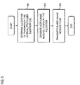
- FIG. 8 is a flowchart of process for extending the on-period for a user equipment with minimal overhead, in accordance with an embodiment of the invention.
- a direct bit indicating the KEEP-AWAKE message is sent over a dedicated control channel, upon detecting that a resource allocation has been granted (steps 801 and 803).
- This approach addresses directly the issues mentioned in the zero-overhead solution and also allows for a non-configured DRX extended mode; e.g., the active mode can always be on.
- the bit can be transmitted as part of the payload, according to one embodiment. Since it is predefined when the KEEP-AWAKE message is sent, the normal rate matching operation can work on both eNB and UE side to "make room" for the additional bit. In this case, the error probability of receiving the KEEP-AWAKE message would correspond to the error rate of the normal packet if encoded together.
- TTI Transmission Time Interval
- a dedicated downlink control channel must be available for sending the KEEP-AWAKE bit.
- FIG. 9 is a graph of a performance comparison relating to the keep-awake mechanism, in accordance with an embodiment of the invention.
- this simulation (as plotted in graph 900), the following assumptions were made: (1) a single-user is scheduled per TTI; and (2) the user is running a 2-hour web-session (e.g., 3GPP HTTP (HyperText Transfer Protocol) traffic model). Also, it is assumed that the UE 101 has a G-factor of OdB, and the system bandwidth is 2.5MHz. Further, a detailed RF modem power consumption model is used that takes into account synchronization, automatic gain control (AGC), etc.
- AGC automatic gain control
- a comparison of the performance of optimally set regular DRX concept e.g., setting DRX period, phase, and on-duration freely
- the metric for performance for example, relates to how much average per-web-page throughput the UE experiences during the 2 hour session compared to how much RF model power is consumed.
- the zero-overhead option is used as reference.
- the packet scheduler 115 always prioritizes the particular DRX user when the user has data buffered for transmission. Also, no allocation table read errors are simulated (e.g., UE 101 always receives the allocation table correctly).
- the keep-awake mechanism can be modified as follows. If the UE 101 is scheduled within the on-duration (can be predefined location as above or more freely defined), the UE 101 automatically stays awake for another on-duration, thereby enhancing the scheduling flexibility for the eNB 103. Depending on the setting for the on-duration, this may cause some degradation in power consumption performance for the UE 101, however. For an on-duration equal to 1 TTI, this scenario is the same as discussed previously.
- FIG. 10 is a flowchart of assigning DRX parameters including a duty cycle parameter and associated duty cycle filter parameter, in accordance with an embodiment of the invention.
- LTE_ACTIVE mode supports DRX/DTX to some level.
- DRX intervals can be supported in LTE ACTIVE up to a length similar to the DRX interval used in LTE_IDLE. This ensures good UE power consumption savings in LTE_ACTIVE, while at the same time reducing the latency of "waking up," as in LTE_ACTIVE mode, most of the radio link parameters have been negotiated.
- the UE 101 in LTE_ACTIVE mode is allowed to sleep when not assigned in uplink/downlink (UL/DL) resources or otherwise performing DL reception or UL transmission.
- Announcements about UL/DL resource allocations for a UE 101 are given on downlink shared control channel (DSCCH) or Allocation Table (AT). Resource allocations for both uplink and downlink are assigned by eNB 103 in the network.
- DSCCH downlink shared control channel
- AT Allocation Table
- the UE 101 reads the DSCCH at every instance of DRX indicating the read-activity. In this manner, the UE 101 knows about the UL/DL resources assigned to it.
- the DRX procedure in certain embodiments, is based on a two level scheme: Regular DRX controlled using RRC signaling, and Interim DRX controlled on a lower layer allowing for shorter reaction times (faster layer) e.g., MAC.
- Regular DRX can be based on requirements of the current connection, and determined and controlled by the network.
- Interim DRX can be used to handle the need for fast change in the DRX for possible increase in assignments of additional resources.
- the operation of interim DRX is also determined and controlled by network.
- the eNB 103 sets the duty cycle parameter and the corresponding duty cycle filter, per step 1001, which can depend on the application/service. These parameters are then formed in a signaling message, as in step 1003. The generated signaling message is forwarded to the UE 101 (step 1005).
- FIG. 11 is a diagram of illustrating the duty cycle parameter, in accordance with an embodiment of the invention.
- the duty cycle controls how long the UE 101 stays awake per DRX timeout in terms of received DSCCH's.
- the DSCCH's received per duty cycle would be received in a continuous manner.
- the duty cycle filter with DRX and duty cycle indicate whether the UE 101 is not supposed to receive the DSCCH's during the duty cycle on period in a continuous manner, but instead with another specific interval (i.e., the indicated filter).
- the purpose of the duty cycle filter or periodicity is to adjust the DRX parameters to limit the amount of H-ARQ (Hybrid Automatic Repeat Request) SAW channels being active for a DRX user.
- duty cycle and duty cycle filter parameters can be assigned together with the DRX parameter(s), or they could be specified by other signaling means or by separate signaling. In one embodiment, duty cycle and duty cycle filter could be applicable for regular DRX only or applicable for both regular and interim DRX.
- the duty cycle and duty cycle filter parameters are used in connection with given DRX parameters.
- the UE is assigned DRX parameters according to the requirements of the current connection. Regular DRX can be used for covering the basic traffic, while interim DRX can be assigned for handling possible needs for (sudden) increase in traffic throughput.
- the duty cycle and corresponding filter parameters can be determined by the network and provided to the UE -- e.g., either in direct signalling together with other DRX parameters, own dedicated signalling message, or even broadcast in system information.
- this value could be the amount of DSCCH allocations the UE 101 receives per DRX, according to one embodiment.
- This parameter can be provided as a timer indicating the time the UE 101 should 'stay awake' per DRX (UE 101 can then receive DSCCH during this time).
- the parameter in one embodiment, can be specified as frames.
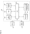
- the computing system 1200 may be coupled via the bus 1201 to a display 1211, such as a liquid crystal display, or active matrix display, for displaying information to a user.
- a display 1211 such as a liquid crystal display, or active matrix display
- An input device 1213 such as a keyboard including alphanumeric and other keys, may be coupled to the bus 1201 for communicating information and command selections to the processor 1203.
- the input device 1213 can include a cursor control, such as a mouse, a trackball, or cursor direction keys, for communicating direction information and command selections to the processor 1203 and for controlling cursor movement on the display 1211.
- the processes described herein can be provided by the computing system 1200 in response to the processor 1203 executing an arrangement of instructions contained in main memory 1205.
- Such instructions can be read into main memory 1205 from another computer-readable medium, such as the storage device 1209.
- Execution of the arrangement of instructions contained in main memory 1205 causes the processor 1203 to perform the process steps described herein.
- processors in a multiprocessing arrangement may also be employed to execute the instructions contained in main memory 1205.
- hard-wired circuitry may be used in place of or in combination with software instructions to implement the embodiment of the invention.
- reconfigurable hardware such as Field Programmable Gate Arrays (FPGAs) can be used, in which the functionality and connection topology of its logic gates are customizable at run-time, typically by programming memory look up tables.
- FPGAs Field Programmable Gate Arrays
- the computing system 1200 also includes at least one communication interface 1215 coupled to bus 1201.
- the communication interface 1215 provides a two-way data communication coupling to a network link (not shown).
- the communication interface 1215 sends and receives electrical, electromagnetic, or optical signals that carry digital data streams representing various types of information.
- the communication interface 1215 can include peripheral interface devices, such as a Universal Serial Bus (USB) interface, a PCMCIA (Personal Computer Memory Card International Association) interface, etc.
- USB Universal Serial Bus
- PCMCIA Personal Computer Memory Card International Association
- the processor 1203 may execute the transmitted code while being received and/or store the code in the storage device 1209, or other non-volatile storage for later execution. In this manner, the computing system 1200 may obtain application code in the form of a carrier wave.
- Non-volatile media include, for example, optical or magnetic disks, such as the storage device 1209.
- Volatile media include dynamic memory, such as main memory 1205.
- Transmission media include coaxial cables, copper wire and fiber optics, including the wires that comprise the bus 1201. Transmission media can also take the form of acoustic, optical, or electromagnetic waves, such as those generated during radio frequency (RF) and infrared (IR) data communications.
- RF radio frequency
- IR infrared
- Computer-readable media include, for example, a floppy disk, a flexible disk, hard disk, magnetic tape, any other magnetic medium, a CD-ROM, CDRW, DVD, any other optical medium, punch cards, paper tape, optical mark sheets, any other physical medium with patterns of holes or other optically recognizable indicia, a RAM, a PROM, and EPROM, a FLASH-EPROM, any other memory chip or cartridge, a carrier wave, or any other medium from which a computer can read.
- a floppy disk a flexible disk, hard disk, magnetic tape, any other magnetic medium, a CD-ROM, CDRW, DVD, any other optical medium, punch cards, paper tape, optical mark sheets, any other physical medium with patterns of holes or other optically recognizable indicia, a RAM, a PROM, and EPROM, a FLASH-EPROM, any other memory chip or cartridge, a carrier wave, or any other medium from which a computer can read.
- the instructions for carrying out at least part of the invention may initially be borne on a magnetic disk of a remote computer.
- the remote computer loads the instructions into main memory and sends the instructions over a telephone line using a modem.
- a modem of a local system receives the data on the telephone line and uses an infrared transmitter to convert the data to an infrared signal and transmit the infrared signal to a portable computing device, such as a personal digital assistant (PDA) or a laptop.
- PDA personal digital assistant
- An infrared detector on the portable computing device receives the information and instructions borne by the infrared signal and places the data on a bus.
- the bus conveys the data to main memory, from which a processor retrieves and executes the instructions.
- the instructions received by main memory can optionally be stored on storage device either before or after execution by processor.
- FIGs. 13A-13D are diagrams of communication systems having exemplary long-term evolution (LTE) architectures, in which the system of FIG. 1 can operate, according to various exemplary embodiments of the invention.
- LTE long-term evolution
- the base station 103 and the UE 101 can communicate in system 1300 using any access scheme, such as Time Division Multiple Access (TDMA), Code Division Multiple Access (CDMA), Wideband Code Division Multiple Access (WCDMA), Orthogonal Frequency Division Multiple Access (OFDMA) or Single Carrier Frequency Division Multiple Access (FDMA) (SC-FDMA) or a combination of thereof.
- TDMA Time Division Multiple Access
- CDMA Code Division Multiple Access
- WCDMA Wideband Code Division Multiple Access
- OFDMA Orthogonal Frequency Division Multiple Access
- SC-FDMA Single Carrier Frequency Division Multiple Access
- both uplink and downlink can utilize WCDMA.
- uplink utilizes SC-FDMA
- downlink utilizes OFDMA.
- the MME (Mobile Management Entity)/Serving Gateways 1301 are connected to the eNBs 103 in a full or partial mesh configuration using tunneling over a packet transport network (e.g., Internet Protocol (IP) network) 1303.
- a packet transport network e.g., Internet Protocol (IP) network
- Exemplary functions of the MME/Serving GW 1301 include distribution of paging messages to the eNBs 103, termination of U-plane packets for paging reasons, and switching of U-plane for support of UE mobility. Since the GWs 1301 serve as a gateway to external networks, e.g., the Internet or private networks 1303, the GWs 1301 include an Access, Authorization and Accounting system (AAA) 1305 to securely determine the identity and privileges of a user and to track each user's activities.
- AAA Access, Authorization and Accounting system
- the MME Serving Gateway 1301 is the key control-node for the LTE access-network and is responsible for idle mode UE tracking and paging procedure including retransmissions. Also, the MME 1301 is involved in the bearer activation/deactivation process and is responsible for selecting the SGW (Serving Gateway) for a UE at the initial attach and at time of intra-LTE handover involving Core Network (CN) node relocation.
- SGW Serving Gateway
- a communication system 1302 supports GERAN (GSM/EDGE radio access) 1304, and UTRAN 1306 based access networks, E-UTRAN 1312 and non-3GPP (not shown) based access networks, and is more fully described in TR 23.882, which is incorporated herein by reference in its entirety.
- GSM/EDGE radio access GSM/EDGE radio access
- UTRAN 1306 based access networks
- E-UTRAN 1312 and non-3GPP (not shown) based access networks and is more fully described in TR 23.882, which is incorporated herein by reference in its entirety.
- MME 1308 control-plane functionality
- Server 1310 bearer-plane functionality
- This scheme enables selection of more cost-effective platforms for, as well as independent scaling of, each of these two elements.
- Service providers can also select optimized topological locations of Serving Gateways 1310 within the network independent of the locations of MMEs 1308 in order to reduce optimized bandwidth latencies and avoid concentrated points of failure.
- the basic architecture of the system 1302 contains following network elements.
- the E-UTRAN e.g., eNB
- the E-UTRAN 1312 interfaces with UE 101 via LTE-Uu.
- the E-UTRAN 1312 supports LTE air interface and includes functions for radio resource control (RRC) functionality corresponding to the control plane MME 1308.
- RRC radio resource control
- the E-UTRAN 1312 also performs a variety of functions including radio resource management, admission control, scheduling, enforcement of negotiated uplink (UL) QoS (Quality of Service), cell information broadcast, ciphering/deciphering of user, compression/decompression of downlink and uplink user plane packet headers and Packet Data Convergence Protocol (PDCP).
- UL uplink
- QoS Quality of Service
- the MME 1308 is involved in the bearer activation/deactivation process and is also responsible for choosing Serving Gateway 1310 for the UE 101.
- MME 1308 functions include Non Access Stratum (NAS) signaling and related security.
- NAS Non Access Stratum
- MME 1308 checks the authorization of the UE 101 to camp on the service provider's Public Land Mobile Network (PLMN) and enforces UE 101 roaming restrictions.
- PLMN Public Land Mobile Network
- the MME 1308 also provides the control plane function for mobility between LTE and 2G/3G access networks with the S3 interface terminating at the MME 1308 from the SGSN (Serving GPRS Support Node) 1314.
- SGSN Serving GPRS Support Node
- the SGSN 1314 is responsible for the delivery of data packets from and to the mobile stations within its geographical service area. Its tasks include packet routing and transfer, mobility management, logical link management, and authentication and charging functions.
- the S6a interface enables transfer of subscription and authentication data for authenticating/authorizing user access to the evolved system (AAA interface) between MME 1308 and HSS (Home Subscriber Server) 1316.
- the S10 interface between MMEs 1308 provides MME relocation and MME 1308 to MME 1308 information transfer.
- the Serving Gateway 1310 is the node that terminates the interface towards the E-UTRAN 1312 via S1-U.
- the S1-U interface provides a per bearer user plane tunneling between the E-UTRAN 1312 and Serving Gateway 1310. It contains support for path switching during handover between eNBs 103.
- the S4 interface provides the user plane with related control and mobility support between SGSN 1314 and the 3GPP Anchor function of Serving Gateway 1310.
- the S12 is an interface between UTRAN 1306 and Serving Gateway 1310.
- Packet Data Network (PDN) Gateway 1318 provides connectivity to the UE 101 to external packet data networks by being the point of exit and entry of traffic for the UE 101.
- the PDN Gateway 1318 performs policy enforcement, packet filtering for each user, charging support, lawful interception and packet screening.
- Another role of the PDN Gateway 1318 is to act as the anchor for mobility between 3GPP and non-3GPP technologies such as WiMax and 3GPP2 (CDMA IX and EvDO (Evolution Data Only)).
- the eNB 103 utilizes an E-UTRA (Evolved Universal Terrestrial Radio Access) (user plane, e.g., RLC (Radio Link Control) 1315, MAC (Media Access Control) 1317, and PHY (Physical) 1319, as well as a control plane (e.g., RRC 1321)).
- the eNB 103 also includes the following functions: Inter Cell RRM (Radio Resource Management) 1323, Connection Mobility Control 1325, RB (Radio Bearer) Control 1327, Radio Admission Control 1329, eNB Measurement Configuration and Provision 1331, and Dynamic Resource Allocation (Scheduler) 1333.
- E-UTRA Evolved Universal Terrestrial Radio Access
- RLC Radio Link Control
- MAC Media Access Control
- PHY Physical
- the eNB 103 also includes the following functions: Inter Cell RRM (Radio Resource Management) 1323, Connection Mobility Control 1325, RB (Radio Bearer) Control 1327, Radio Admission Control 1329, eNB Measurement Configuration and Provision
- the eNB 103 communicates with the aGW 1301 (Access Gateway) via an S1 interface.
- the aGW 1301 includes a User Plane 1301a and a Control plane 1301b.
- the control plane 1301b provides the following components: SAE (System Architecture Evolution) Bearer Control 1335 and MM (Mobile Management) Entity 1337.
- the user plane 1301b includes a PDCP (Packet Data Convergence Protocol) 1339 and a user plane functions 1341. It is noted that the functionality of the aGW 1301 can also be provided by a combination of a serving gateway (SGW) and a packet data network (PDN) GW.
- SGW serving gateway
- PDN packet data network
- the aGW 1301 can also interface with a packet network, such as the Internet 1343.
- the PDCP Packet Data Convergence Protocol
- the eNB functions of FIG. 13C are also provided in this architecture.
- E-UTRAN Evolved Packet Core
- EPC Evolved Packet Core
- radio protocol architecture of E-UTRAN is provided for the user plane and the control plane.
- 3GPP TS 36.300 A more detailed description of the architecture is provided in 3GPP TS 36.300.
- the eNB 103 interfaces via the S1 to the Serving Gateway 1345, which includes a Mobility Anchoring function 1347.
- the MME (Mobility Management Entity) 1349 provides SAE (System Architecture Evolution) Bearer Control 1351, Idle State Mobility Handling 1353, and NAS (Non-Access Stratum) Security 1355.
- SAE System Architecture Evolution
- Idle State Mobility Handling 1353 Idle State Mobility Handling 1353
- NAS Non-Access Stratum
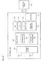
- FIG. 14 is a diagram of exemplary components of an LTE terminal capable of operating in the systems of FIGs. 13A-13D , according to an embodiment of the invention.
- An LTE terminal 1400 is configured to operate in a Multiple Input Multiple Output (MIMO) system. Consequently, an antenna system 1401 provides for multiple antennas to receive and transmit signals.
- the antenna system 1401 is coupled to radio circuitry 1403, which includes multiple transmitters 1405 and receivers 1407.
- the radio circuitry encompasses all of the Radio Frequency (RF) circuitry as well as base-band processing circuitry.
- layer-1 (LI) and layer-2 (L2) processing are provided by units 1409 and 1411, respectively.
- layer-3 functions can be provided (not shown).
- Module 1413 executes all MAC layer functions.
- a timing and calibration module 1415 maintains proper timing by interfacing, for example, an external timing reference (not shown). Additionally, a processor 1417 is included. Under this scenario, the LTE terminal 1400 communicates with a computing device 1419, which can be a personal computer, work station, a PDA, web appliance, cellular phone, etc.
Landscapes
- Engineering & Computer Science (AREA)
- Computer Networks & Wireless Communication (AREA)
- Signal Processing (AREA)
- Mobile Radio Communication Systems (AREA)
Priority Applications (1)
| Application Number | Priority Date | Filing Date | Title |
|---|---|---|---|
| PL19173705T PL3557917T3 (pl) | 2007-02-06 | 2008-02-06 | Sposób i urządzenie do zapewnienia wydajnej komunikacji nieciągłej |
Applications Claiming Priority (4)
| Application Number | Priority Date | Filing Date | Title |
|---|---|---|---|
| US88851407P | 2007-02-06 | 2007-02-06 | |
| EP08709775.4A EP2127419B1 (fr) | 2007-02-06 | 2008-02-06 | Procédé et appareil pour fournir une communication discontinue efficace |
| US12/027,061 US9918277B2 (en) | 2007-02-06 | 2008-02-06 | Method and apparatus for providing efficient discontinuous communication |
| PCT/IB2008/000267 WO2008096243A2 (fr) | 2007-02-06 | 2008-02-06 | Procédé et appareil pour fournir une communication discontinue efficace |
Related Parent Applications (2)
| Application Number | Title | Priority Date | Filing Date |
|---|---|---|---|
| EP08709775.4A Division-Into EP2127419B1 (fr) | 2007-02-06 | 2008-02-06 | Procédé et appareil pour fournir une communication discontinue efficace |
| EP08709775.4A Division EP2127419B1 (fr) | 2007-02-06 | 2008-02-06 | Procédé et appareil pour fournir une communication discontinue efficace |
Publications (2)
| Publication Number | Publication Date |
|---|---|
| EP3557917A1 true EP3557917A1 (fr) | 2019-10-23 |
| EP3557917B1 EP3557917B1 (fr) | 2020-05-13 |
Family
ID=39676075
Family Applications (2)
| Application Number | Title | Priority Date | Filing Date |
|---|---|---|---|
| EP19173705.5A Active EP3557917B1 (fr) | 2007-02-06 | 2008-02-06 | Procédé et appareil pour fournir une communication discontinue efficace |
| EP08709775.4A Active EP2127419B1 (fr) | 2007-02-06 | 2008-02-06 | Procédé et appareil pour fournir une communication discontinue efficace |
Family Applications After (1)
| Application Number | Title | Priority Date | Filing Date |
|---|---|---|---|
| EP08709775.4A Active EP2127419B1 (fr) | 2007-02-06 | 2008-02-06 | Procédé et appareil pour fournir une communication discontinue efficace |
Country Status (9)
| Country | Link |
|---|---|
| US (2) | US9918277B2 (fr) |
| EP (2) | EP3557917B1 (fr) |
| JP (1) | JP5583975B2 (fr) |
| KR (1) | KR101084844B1 (fr) |
| DK (1) | DK2127419T3 (fr) |
| ES (2) | ES2806927T3 (fr) |
| HU (1) | HUE049910T2 (fr) |
| PL (2) | PL3557917T3 (fr) |
| WO (1) | WO2008096243A2 (fr) |
Families Citing this family (61)
| Publication number | Priority date | Publication date | Assignee | Title |
|---|---|---|---|---|
| US20130258919A1 (en) * | 2007-02-05 | 2013-10-03 | Qualcomm Incorporated | Flexible dtx and drx in a wireless communication system |
| JP4932521B2 (ja) * | 2007-02-09 | 2012-05-16 | 株式会社エヌ・ティ・ティ・ドコモ | 移動通信システムで使用される基地局装置及び方法 |
| US7813371B2 (en) * | 2007-03-21 | 2010-10-12 | Kapsch Trafficcom Ag | System and method for short range communication using adaptive channel intervals |
| ES2532681T3 (es) * | 2007-03-26 | 2015-03-30 | Samsung Electronics Co., Ltd. | Procedimiento y aparato de recepción discontinua de un equipo de usuario en un sistema de comunicación móvil |
| US20080267168A1 (en) * | 2007-04-27 | 2008-10-30 | Zhijun Cai | Slow Adaptation of Modulation and Coding for Packet Transmission |
| CA2690430A1 (fr) * | 2007-06-15 | 2008-12-18 | Research In Motion Limited | Systeme et procede pour une reduction de surdebit d'adaptation de liaison |
| AU2007354841B2 (en) | 2007-06-15 | 2011-11-24 | Blackberry Limited | System and method for semi-persistent and dynamic scheduling and discontinuous reception control |
| WO2008151411A1 (fr) * | 2007-06-15 | 2008-12-18 | Research In Motion Limited | Système et procédé pour une distribution de gros paquets pendant une session attribuée de façon semi-persistante |
| KR101504764B1 (ko) * | 2007-06-20 | 2015-03-20 | 삼성전자주식회사 | 이동통신 시스템에서 불연속 수신을 수행하는 통신 장치 및방법 |
| US20090046639A1 (en) * | 2007-08-14 | 2009-02-19 | Zhijun Cai | System and Method for Handling Large IP Packets During VoIP Session |
| ES2558744T3 (es) * | 2007-09-14 | 2016-02-08 | Blackberry Limited | Sistema y método para el tiempo de inicio de control de recepción discontinua |
| CA2710305C (fr) * | 2007-12-20 | 2013-09-17 | Research In Motion Limited | Equipements et procedes de synchronisation de rythme en liaison montante |
| WO2009085973A2 (fr) * | 2007-12-21 | 2009-07-09 | Research In Motion Limited | Système et procédé pour utilisation de ressource en liaison ascendante |
| KR101375734B1 (ko) * | 2008-01-22 | 2014-03-19 | 삼성전자주식회사 | 무선통신시스템에서 과금 장치 및 방법 |
| US8606336B2 (en) | 2008-03-20 | 2013-12-10 | Blackberry Limited | System and method for uplink timing synchronization in conjunction with discontinuous reception |
| US8300757B2 (en) | 2008-08-08 | 2012-10-30 | Motorola Mobility Llc | Methods for detection of failure and recovery in a radio link |
| US8874065B2 (en) * | 2008-10-09 | 2014-10-28 | Qualcomm Incorporated | Method and apparatus for facilitating power conservation via time-gating in a wireless communication system |
| US8442021B2 (en) | 2008-11-07 | 2013-05-14 | Motorola Mobility Llc | Radio link performance prediction in wireless communication terminal |
| US8457112B2 (en) | 2008-11-07 | 2013-06-04 | Motorola Mobility Llc | Radio link performance prediction in wireless communication terminal |
| KR20100089006A (ko) | 2009-02-02 | 2010-08-11 | 엘지전자 주식회사 | 전력소모방지모드에서 신뢰성 있는 메시지 전송방법 |
| US20100208660A1 (en) * | 2009-02-19 | 2010-08-19 | Samsung Electronics Co., Ltd. | Method for distributed drx operation for ease of scheduling and effective power saving |
| US8953581B1 (en) | 2009-05-13 | 2015-02-10 | Dust Networks, Inc. | Timing synchronization for wireless networks |
| US9143980B2 (en) | 2010-01-04 | 2015-09-22 | Telefonaktiebolaget L M Ericsson (Publ) | Methods and arrangements for optimizing radio resource utilization at group communications |
| CN102137381B (zh) * | 2010-11-09 | 2014-06-25 | 华为终端有限公司 | 通过家庭基站进行网络通信的方法、装置及系统 |
| US9100913B2 (en) | 2010-11-15 | 2015-08-04 | Samsung Electronics Co., Ltd. | Method and apparatus for optimizing power consumption of a terminal in a mobile communication system |
| US9681385B2 (en) | 2010-11-15 | 2017-06-13 | Samsung Electronics Co., Ltd | Method and apparatus for optimizing power consumption of a terminal in a mobile communication system |
| EP2654348A4 (fr) * | 2010-12-15 | 2014-01-08 | Fujitsu Ltd | Dispositif de communication sans fil |
| KR20120067856A (ko) | 2010-12-16 | 2012-06-26 | 한국전자통신연구원 | 단말의 저전력 운용을 위한 무선 통신 시스템 및 무선 통신 시스템의 동작 방법 |
| TWI533629B (zh) * | 2010-12-28 | 2016-05-11 | 內數位專利控股公司 | 非附於無線網路之觸發裝置 |
| US20130170415A1 (en) * | 2011-04-04 | 2013-07-04 | Kyocera Corporation | Mobile communication method and radio terminal |
| WO2012141630A1 (fr) * | 2011-04-14 | 2012-10-18 | Telefonaktiebolaget L M Ericsson (Publ) | Procédés et nœuds de réseau pour définir une valeur de temporisation |
| US20130210481A1 (en) * | 2012-02-15 | 2013-08-15 | Sachin Sane | Methods and apparatus for intelligent wirless technology selection |
| WO2013187693A1 (fr) * | 2012-06-12 | 2013-12-19 | 삼성전자 주식회사 | Procédé et dispositif d'émission et de réception d'une petite quantité de données dans un système de communication mobile |
| JP5524291B2 (ja) * | 2012-07-20 | 2014-06-18 | 株式会社Nttドコモ | 移動局 |
| WO2014062103A1 (fr) | 2012-10-15 | 2014-04-24 | Telefonaktiebolaget L M Ericsson (Publ) | Procédé, dispositif réseau, programme informatique et produit de programme informatique permettant de déterminer un ensemble de paramètres d'état d'alimentation |
| JP6082288B2 (ja) | 2012-10-16 | 2017-02-15 | シャープ株式会社 | 無線通信システム |
| US9647818B2 (en) | 2013-01-03 | 2017-05-09 | Intel IP Corporation | Apparatus and method for single-tone device discovery in wireless communication networks |
| JP6094297B2 (ja) * | 2013-03-21 | 2017-03-15 | 富士通株式会社 | 無線端末装置、通信制御装置、及び無線通信方法 |
| CN105103634B (zh) | 2013-03-29 | 2019-03-22 | 英特尔Ip公司 | 无线通信网络中的扩展型呼叫非连续接收(drx)周期 |
| CN104995961B (zh) | 2013-03-29 | 2018-10-02 | 英特尔Ip公司 | 漫游情景中wlan选择策略的控制 |
| US9191178B2 (en) | 2013-04-04 | 2015-11-17 | Intel IP Corporation | Enhanced node B and method for RRC connection establishment for small data transfers |
| WO2014174806A1 (fr) | 2013-04-22 | 2014-10-30 | パナソニック株式会社 | Procédé de fabrication d'un appareil d'affichage el |
| JP6343432B2 (ja) * | 2013-06-25 | 2018-06-13 | 株式会社Nttドコモ | 移動局 |
| WO2015016755A1 (fr) * | 2013-08-02 | 2015-02-05 | Telefonaktiebolaget L M Ericsson (Publ) | Procédés, nœud de réseau, dispositif sans fil, programmes informatiques et produits-programmes informatiques destinés à être utilisés en réception discontinue |
| US20150208276A1 (en) * | 2014-01-20 | 2015-07-23 | Vodafone Ip Licensing Limited | Congestion detection |
| US10219292B2 (en) * | 2014-10-24 | 2019-02-26 | Qualcomm Incorporated | Flexible multiplexing and feedback for variable transmission time intervals |
| US20170265133A1 (en) * | 2014-12-01 | 2017-09-14 | Nokia Solutions And Networks Oy | Inactive communication mode |
| JP6538868B2 (ja) * | 2015-03-11 | 2019-07-03 | ノキア ソリューションズ アンド ネットワークス オサケユキチュア | 接続モード・ユーザ装置のための拡張間欠受信シグナリング |
| US10805000B2 (en) | 2015-07-23 | 2020-10-13 | Qualcomm Incorporated | Method and apparatus for discontinuous transmission in bent-pipe relay in satellite communication systems |
| CN105743976A (zh) * | 2016-01-28 | 2016-07-06 | 浪潮电子信息产业股份有限公司 | 一种基于双通道数据传输机制的安全基线数据通信方法 |
| EP3446423B1 (fr) | 2016-04-19 | 2021-09-22 | Telefonaktiebolaget LM Ericsson (PUBL) | Utilisation d'une procédure de transmission plus robuste |
| CN109314923B (zh) * | 2016-06-30 | 2020-11-17 | 华为技术有限公司 | 一种站点唤醒方法、相关设备和系统 |
| WO2018035224A1 (fr) | 2016-08-16 | 2018-02-22 | Convida Wireless, Llc | Maintien d'un équipement d'utilisateur à l'état éveillé |
| CN109548146B (zh) * | 2017-08-02 | 2023-10-27 | 阿里巴巴集团控股有限公司 | 通讯方法及装置 |
| EP3834525A1 (fr) * | 2018-08-09 | 2021-06-16 | Sharp Kabushiki Kaisha | Modification de l'état de signalisation de réveil d'un terminal sans fil |
| CN113329449B (zh) | 2019-05-30 | 2023-05-12 | Oppo广东移动通信有限公司 | 一种bwp的管理方法及装置、终端 |
| US10517106B1 (en) * | 2019-05-30 | 2019-12-24 | Cypress Semiconductor Corporation | Systems, methods, and devices for network request scheduling |
| CN113906823A (zh) * | 2019-06-13 | 2022-01-07 | 索尼集团公司 | 用于基于能力来配置终端的方法和网络节点 |
| WO2021087678A1 (fr) | 2019-11-04 | 2021-05-14 | Oppo广东移动通信有限公司 | Procédé et appareil de gestion d'état de cellule, dispositif terminal et dispositif réseau |
| CN115280689B (zh) * | 2020-03-09 | 2024-06-25 | 联发科技(新加坡)私人有限公司 | 非地面网络通信中的波束使用管理 |
| US12328149B1 (en) * | 2023-02-02 | 2025-06-10 | Rockwell Collins, Inc. | Notification system and apparatus |
Citations (4)
| Publication number | Priority date | Publication date | Assignee | Title |
|---|---|---|---|---|
| EP1317156A1 (fr) * | 2001-11-28 | 2003-06-04 | Alcatel | Procédé d'opérer une station mobile dans un mode d'économie d'énergie |
| DE10235470A1 (de) * | 2002-08-02 | 2004-02-19 | Siemens Ag | Verfahren, Teilnehmergerät sowie Funkkommunikationssystem zum Übertragen von Nutzdatennachrichten |
| US20060195576A1 (en) * | 2005-02-28 | 2006-08-31 | Mika Rinne | Discontinuous transmission/reception in a communications system |
| WO2006114710A2 (fr) * | 2005-02-28 | 2006-11-02 | Nokia Corporation | Reception/transmission discontinue dans un systeme de communications |
Family Cites Families (8)
| Publication number | Priority date | Publication date | Assignee | Title |
|---|---|---|---|---|
| JP3629077B2 (ja) * | 1995-12-08 | 2005-03-16 | 富士通株式会社 | 無線通信システム,無線通信システム用基地局および間欠電源投入型移動局 |
| MXPA01000893A (es) * | 1998-07-27 | 2002-06-04 | Webtv Networks Inc | Acceso remoto a computadora. |
| US20020082910A1 (en) * | 2000-12-22 | 2002-06-27 | Leandros Kontogouris | Advertising system and method which provides advertisers with an accurate way of measuring response, and banner advertisement therefor |
| JP2003229811A (ja) * | 2002-02-06 | 2003-08-15 | Sony Corp | 無線通信システム、基地局および無線通信端末 |
| KR100457537B1 (ko) | 2002-12-02 | 2004-11-17 | 삼성전자주식회사 | 애드-혹 네트워크에서의 전력 소모 감소 장치 및 방법 |
| US20080084845A1 (en) * | 2006-10-06 | 2008-04-10 | Motorola, Inc. | Wireless communication system frame structure having variable sized cyclic prefix |
| TWI463894B (zh) * | 2006-10-27 | 2014-12-01 | 內數位科技公司 | 無線系統中增強不連續接收方法及裝置 |
| KR20080084533A (ko) | 2007-03-16 | 2008-09-19 | 엘지전자 주식회사 | 이동통신 시스템에서의 데이터 통신 방법 |
-
2008
- 2008-02-06 KR KR1020097018546A patent/KR101084844B1/ko active Active
- 2008-02-06 ES ES19173705T patent/ES2806927T3/es active Active
- 2008-02-06 WO PCT/IB2008/000267 patent/WO2008096243A2/fr not_active Ceased
- 2008-02-06 HU HUE19173705A patent/HUE049910T2/hu unknown
- 2008-02-06 ES ES08709775T patent/ES2748148T3/es active Active
- 2008-02-06 EP EP19173705.5A patent/EP3557917B1/fr active Active
- 2008-02-06 JP JP2009548761A patent/JP5583975B2/ja active Active
- 2008-02-06 US US12/027,061 patent/US9918277B2/en active Active
- 2008-02-06 PL PL19173705T patent/PL3557917T3/pl unknown
- 2008-02-06 EP EP08709775.4A patent/EP2127419B1/fr active Active
- 2008-02-06 PL PL08709775T patent/PL2127419T3/pl unknown
- 2008-02-06 DK DK08709775.4T patent/DK2127419T3/da active
-
2018
- 2018-01-29 US US15/882,582 patent/US10015747B2/en active Active
Patent Citations (4)
| Publication number | Priority date | Publication date | Assignee | Title |
|---|---|---|---|---|
| EP1317156A1 (fr) * | 2001-11-28 | 2003-06-04 | Alcatel | Procédé d'opérer une station mobile dans un mode d'économie d'énergie |
| DE10235470A1 (de) * | 2002-08-02 | 2004-02-19 | Siemens Ag | Verfahren, Teilnehmergerät sowie Funkkommunikationssystem zum Übertragen von Nutzdatennachrichten |
| US20060195576A1 (en) * | 2005-02-28 | 2006-08-31 | Mika Rinne | Discontinuous transmission/reception in a communications system |
| WO2006114710A2 (fr) * | 2005-02-28 | 2006-11-02 | Nokia Corporation | Reception/transmission discontinue dans un systeme de communications |
Non-Patent Citations (2)
| Title |
|---|
| "DRX Scheme (Doc. No. R2-0632248)", 6 November 2006 (2006-11-06), Riga, LATVIA, XP002504706, Retrieved from the Internet <URL:ftp://ftp.3gpp.org/tsg_ran/WG2_RL2/TSGR2_56/Documents/R2-063248.zip> [retrieved on 20081111] * |
| "Views on DRX/DTX control in LTE (Doc. No. R2-063397)", 6 November 2006 (2006-11-06), XP007905621, Retrieved from the Internet <URL:ftp://ftp.3gpp.org/tsg_ran/WG2_RL2/TSGR2_56/Documents/R2-063397.zip> [retrieved on 20080909] * |
Also Published As
| Publication number | Publication date |
|---|---|
| JP2010518721A (ja) | 2010-05-27 |
| EP2127419A2 (fr) | 2009-12-02 |
| ES2748148T3 (es) | 2020-03-13 |
| JP5583975B2 (ja) | 2014-09-03 |
| EP2127419B1 (fr) | 2019-07-03 |
| PL2127419T3 (pl) | 2019-11-29 |
| HUE049910T2 (hu) | 2020-11-30 |
| US10015747B2 (en) | 2018-07-03 |
| WO2008096243A2 (fr) | 2008-08-14 |
| ES2806927T3 (es) | 2021-02-19 |
| DK2127419T3 (da) | 2019-09-23 |
| US20080186893A1 (en) | 2008-08-07 |
| US9918277B2 (en) | 2018-03-13 |
| EP3557917B1 (fr) | 2020-05-13 |
| KR101084844B1 (ko) | 2011-11-21 |
| WO2008096243A3 (fr) | 2009-02-05 |
| PL3557917T3 (pl) | 2020-09-21 |
| CN101637052A (zh) | 2010-01-27 |
| KR20090117789A (ko) | 2009-11-12 |
| US20180152892A1 (en) | 2018-05-31 |
Similar Documents
| Publication | Publication Date | Title |
|---|---|---|
| US10015747B2 (en) | Method and apparatus for providing efficient discontinuous communication | |
| US20080268863A1 (en) | Method and Apparatus for Reporting Channel Quality | |
| CN113873628B (zh) | 监听wus的方法、发送信息的方法及设备 | |
| CN109981237B (zh) | 基站、移动台及其方法 | |
| CN101730219B (zh) | 管理不连续接收的偏移操作的方法及其相关通讯装置 | |
| CN104160761B (zh) | 用于采用寻呼循环学习模式的装置和方法 | |
| US20170303335A1 (en) | System and Method for Uplink Timing Synchronization in Conjunction with Discontinuous Reception | |
| CN110199547B (zh) | 用于确定非连续接收状态的方法、终端设备和网络设备 | |
| US20120113875A1 (en) | Method and apparatus for dynamically modifying a transmission frame | |
| RU2735132C1 (ru) | Способ связи, оконечное устройство и сетевое устройство | |
| US20100113023A1 (en) | Method and Apparatus For Setting Discontinuous Communication Interval | |
| CN117397310A (zh) | 一种drx配置方法及装置、终端设备、网络设备 | |
| JP2018014747A (ja) | 追加のウェイクアップ機会を有する改良された不連続受信動作 | |
| US20240015840A1 (en) | Method and apparatus for triggering a sidelink discontinuous reception command and system | |
| CN103597771B (zh) | 用于载波聚合的不连续接收 | |
| US20090319903A1 (en) | Method and apparatus for distributing system information windows | |
| WO2021088017A1 (fr) | Procédé de détermination de type d'informations de commande de liaison descendante, et appareil | |
| CN121549059A (zh) | 用户设备和基站 | |
| WO2009057045A2 (fr) | Procédé et appareil pour réactiver un canal de données | |
| WO2009022309A2 (fr) | Procédé et appareil servant à fournir un procédé de signalisation d'attribution de ressources adaptable | |
| HK1132409A (en) | Method and apparatus for providing efficient discontinuous communication | |
| HK1132409B (en) | Method and apparatus for providing efficient discontinuous communication | |
| CN101637052B (zh) | 用于提供有效不连续通信的方法和设备 | |
| CN121693978A (zh) | 用于小区dtx/drx激活/去激活和ue行为的组公共dci设计 |
Legal Events
| Date | Code | Title | Description |
|---|---|---|---|
| PUAI | Public reference made under article 153(3) epc to a published international application that has entered the european phase |
Free format text: ORIGINAL CODE: 0009012 |
|
| STAA | Information on the status of an ep patent application or granted ep patent |
Free format text: STATUS: THE APPLICATION HAS BEEN PUBLISHED |
|
| STAA | Information on the status of an ep patent application or granted ep patent |
Free format text: STATUS: REQUEST FOR EXAMINATION WAS MADE |
|
| AC | Divisional application: reference to earlier application |
Ref document number: 2127419 Country of ref document: EP Kind code of ref document: P |
|
| AK | Designated contracting states |
Kind code of ref document: A1 Designated state(s): AT BE BG CH CY CZ DE DK EE ES FI FR GB GR HR HU IE IS IT LI LT LU LV MC MT NL NO PL PT RO SE SI SK TR |
|
| 17P | Request for examination filed |
Effective date: 20190919 |
|
| RBV | Designated contracting states (corrected) |
Designated state(s): AT BE BG CH CY CZ DE DK EE ES FI FR GB GR HR HU IE IS IT LI LT LU LV MC MT NL NO PL PT RO SE SI SK TR |
|
| GRAP | Despatch of communication of intention to grant a patent |
Free format text: ORIGINAL CODE: EPIDOSNIGR1 |
|
| STAA | Information on the status of an ep patent application or granted ep patent |
Free format text: STATUS: GRANT OF PATENT IS INTENDED |
|
| INTG | Intention to grant announced |
Effective date: 20191217 |
|
| GRAS | Grant fee paid |
Free format text: ORIGINAL CODE: EPIDOSNIGR3 |
|
| GRAA | (expected) grant |
Free format text: ORIGINAL CODE: 0009210 |
|
| STAA | Information on the status of an ep patent application or granted ep patent |
Free format text: STATUS: THE PATENT HAS BEEN GRANTED |
|
| AC | Divisional application: reference to earlier application |
Ref document number: 2127419 Country of ref document: EP Kind code of ref document: P |
|
| AK | Designated contracting states |
Kind code of ref document: B1 Designated state(s): AT BE BG CH CY CZ DE DK EE ES FI FR GB GR HR HU IE IS IT LI LT LU LV MC MT NL NO PL PT RO SE SI SK TR |
|
| REG | Reference to a national code |
Ref country code: GB Ref legal event code: FG4D |
|
| REG | Reference to a national code |
Ref country code: CH Ref legal event code: EP |
|
| REG | Reference to a national code |
Ref country code: DE Ref legal event code: R096 Ref document number: 602008062736 Country of ref document: DE |
|
| REG | Reference to a national code |
Ref country code: AT Ref legal event code: REF Ref document number: 1271884 Country of ref document: AT Kind code of ref document: T Effective date: 20200615 |
|
| REG | Reference to a national code |
Ref country code: NL Ref legal event code: FP |
|
| REG | Reference to a national code |
Ref country code: SE Ref legal event code: TRGR |
|
| REG | Reference to a national code |
Ref country code: LT Ref legal event code: MG4D |
|
| PG25 | Lapsed in a contracting state [announced via postgrant information from national office to epo] |
Ref country code: GR Free format text: LAPSE BECAUSE OF FAILURE TO SUBMIT A TRANSLATION OF THE DESCRIPTION OR TO PAY THE FEE WITHIN THE PRESCRIBED TIME-LIMIT Effective date: 20200814 Ref country code: NO Free format text: LAPSE BECAUSE OF FAILURE TO SUBMIT A TRANSLATION OF THE DESCRIPTION OR TO PAY THE FEE WITHIN THE PRESCRIBED TIME-LIMIT Effective date: 20200813 Ref country code: LT Free format text: LAPSE BECAUSE OF FAILURE TO SUBMIT A TRANSLATION OF THE DESCRIPTION OR TO PAY THE FEE WITHIN THE PRESCRIBED TIME-LIMIT Effective date: 20200513 Ref country code: PT Free format text: LAPSE BECAUSE OF FAILURE TO SUBMIT A TRANSLATION OF THE DESCRIPTION OR TO PAY THE FEE WITHIN THE PRESCRIBED TIME-LIMIT Effective date: 20200914 Ref country code: FI Free format text: LAPSE BECAUSE OF FAILURE TO SUBMIT A TRANSLATION OF THE DESCRIPTION OR TO PAY THE FEE WITHIN THE PRESCRIBED TIME-LIMIT Effective date: 20200513 Ref country code: IS Free format text: LAPSE BECAUSE OF FAILURE TO SUBMIT A TRANSLATION OF THE DESCRIPTION OR TO PAY THE FEE WITHIN THE PRESCRIBED TIME-LIMIT Effective date: 20200913 |
|
| PG25 | Lapsed in a contracting state [announced via postgrant information from national office to epo] |
Ref country code: HR Free format text: LAPSE BECAUSE OF FAILURE TO SUBMIT A TRANSLATION OF THE DESCRIPTION OR TO PAY THE FEE WITHIN THE PRESCRIBED TIME-LIMIT Effective date: 20200513 Ref country code: LV Free format text: LAPSE BECAUSE OF FAILURE TO SUBMIT A TRANSLATION OF THE DESCRIPTION OR TO PAY THE FEE WITHIN THE PRESCRIBED TIME-LIMIT Effective date: 20200513 Ref country code: BG Free format text: LAPSE BECAUSE OF FAILURE TO SUBMIT A TRANSLATION OF THE DESCRIPTION OR TO PAY THE FEE WITHIN THE PRESCRIBED TIME-LIMIT Effective date: 20200813 |
|
| REG | Reference to a national code |
Ref country code: HU Ref legal event code: AG4A Ref document number: E049910 Country of ref document: HU |
|
| REG | Reference to a national code |
Ref country code: AT Ref legal event code: MK05 Ref document number: 1271884 Country of ref document: AT Kind code of ref document: T Effective date: 20200513 |
|
| PG25 | Lapsed in a contracting state [announced via postgrant information from national office to epo] |
Ref country code: CZ Free format text: LAPSE BECAUSE OF FAILURE TO SUBMIT A TRANSLATION OF THE DESCRIPTION OR TO PAY THE FEE WITHIN THE PRESCRIBED TIME-LIMIT Effective date: 20200513 Ref country code: EE Free format text: LAPSE BECAUSE OF FAILURE TO SUBMIT A TRANSLATION OF THE DESCRIPTION OR TO PAY THE FEE WITHIN THE PRESCRIBED TIME-LIMIT Effective date: 20200513 Ref country code: AT Free format text: LAPSE BECAUSE OF FAILURE TO SUBMIT A TRANSLATION OF THE DESCRIPTION OR TO PAY THE FEE WITHIN THE PRESCRIBED TIME-LIMIT Effective date: 20200513 Ref country code: DK Free format text: LAPSE BECAUSE OF FAILURE TO SUBMIT A TRANSLATION OF THE DESCRIPTION OR TO PAY THE FEE WITHIN THE PRESCRIBED TIME-LIMIT Effective date: 20200513 |
|
| REG | Reference to a national code |
Ref country code: DE Ref legal event code: R097 Ref document number: 602008062736 Country of ref document: DE |
|
| REG | Reference to a national code |
Ref country code: ES Ref legal event code: FG2A Ref document number: 2806927 Country of ref document: ES Kind code of ref document: T3 Effective date: 20210219 |
|
| PG25 | Lapsed in a contracting state [announced via postgrant information from national office to epo] |
Ref country code: SK Free format text: LAPSE BECAUSE OF FAILURE TO SUBMIT A TRANSLATION OF THE DESCRIPTION OR TO PAY THE FEE WITHIN THE PRESCRIBED TIME-LIMIT Effective date: 20200513 |
|
| PLBE | No opposition filed within time limit |
Free format text: ORIGINAL CODE: 0009261 |
|
| STAA | Information on the status of an ep patent application or granted ep patent |
Free format text: STATUS: NO OPPOSITION FILED WITHIN TIME LIMIT |
|
| 26N | No opposition filed |
Effective date: 20210216 |
|
| PG25 | Lapsed in a contracting state [announced via postgrant information from national office to epo] |
Ref country code: MC Free format text: LAPSE BECAUSE OF FAILURE TO SUBMIT A TRANSLATION OF THE DESCRIPTION OR TO PAY THE FEE WITHIN THE PRESCRIBED TIME-LIMIT Effective date: 20200513 |
|
| REG | Reference to a national code |
Ref country code: BE Ref legal event code: MM Effective date: 20210228 |
|
| PG25 | Lapsed in a contracting state [announced via postgrant information from national office to epo] |
Ref country code: LI Free format text: LAPSE BECAUSE OF NON-PAYMENT OF DUE FEES Effective date: 20210228 Ref country code: LU Free format text: LAPSE BECAUSE OF NON-PAYMENT OF DUE FEES Effective date: 20210206 Ref country code: CH Free format text: LAPSE BECAUSE OF NON-PAYMENT OF DUE FEES Effective date: 20210228 |
|
| PG25 | Lapsed in a contracting state [announced via postgrant information from national office to epo] |
Ref country code: IE Free format text: LAPSE BECAUSE OF NON-PAYMENT OF DUE FEES Effective date: 20210206 |
|
| REG | Reference to a national code |
Ref country code: DE Ref legal event code: R039 Ref document number: 602008062736 Country of ref document: DE Ref country code: DE Ref legal event code: R008 Ref document number: 602008062736 Country of ref document: DE |
|
| PG25 | Lapsed in a contracting state [announced via postgrant information from national office to epo] |
Ref country code: BE Free format text: LAPSE BECAUSE OF NON-PAYMENT OF DUE FEES Effective date: 20210228 |
|
| PG25 | Lapsed in a contracting state [announced via postgrant information from national office to epo] |
Ref country code: CY Free format text: LAPSE BECAUSE OF FAILURE TO SUBMIT A TRANSLATION OF THE DESCRIPTION OR TO PAY THE FEE WITHIN THE PRESCRIBED TIME-LIMIT Effective date: 20200513 |
|
| P01 | Opt-out of the competence of the unified patent court (upc) registered |
Effective date: 20230527 |
|
| PG25 | Lapsed in a contracting state [announced via postgrant information from national office to epo] |
Ref country code: SI Free format text: LAPSE BECAUSE OF FAILURE TO SUBMIT A TRANSLATION OF THE DESCRIPTION OR TO PAY THE FEE WITHIN THE PRESCRIBED TIME-LIMIT Effective date: 20200513 |
|
| REG | Reference to a national code |
Ref country code: DE Ref legal event code: R040 Ref document number: 602008062736 Country of ref document: DE |
|
| PG25 | Lapsed in a contracting state [announced via postgrant information from national office to epo] |
Ref country code: TR Free format text: LAPSE BECAUSE OF FAILURE TO SUBMIT A TRANSLATION OF THE DESCRIPTION OR TO PAY THE FEE WITHIN THE PRESCRIBED TIME-LIMIT Effective date: 20200513 |
|
| PG25 | Lapsed in a contracting state [announced via postgrant information from national office to epo] |
Ref country code: MT Free format text: LAPSE BECAUSE OF FAILURE TO SUBMIT A TRANSLATION OF THE DESCRIPTION OR TO PAY THE FEE WITHIN THE PRESCRIBED TIME-LIMIT Effective date: 20200513 |
|
| PGFP | Annual fee paid to national office [announced via postgrant information from national office to epo] |
Ref country code: FR Payment date: 20251231 Year of fee payment: 19 |
|
| PGFP | Annual fee paid to national office [announced via postgrant information from national office to epo] |
Ref country code: NL Payment date: 20260106 Year of fee payment: 19 |
|
| PGFP | Annual fee paid to national office [announced via postgrant information from national office to epo] |
Ref country code: HU Payment date: 20260130 Year of fee payment: 19 |
|
| PGFP | Annual fee paid to national office [announced via postgrant information from national office to epo] |
Ref country code: SE Payment date: 20251230 Year of fee payment: 19 |
|
| PGFP | Annual fee paid to national office [announced via postgrant information from national office to epo] |
Ref country code: GB Payment date: 20260106 Year of fee payment: 19 |
|
| PGFP | Annual fee paid to national office [announced via postgrant information from national office to epo] |
Ref country code: ES Payment date: 20260305 Year of fee payment: 19 |
|
| PGFP | Annual fee paid to national office [announced via postgrant information from national office to epo] |
Ref country code: DE Payment date: 20251230 Year of fee payment: 19 |
|
| PGFP | Annual fee paid to national office [announced via postgrant information from national office to epo] |
Ref country code: RO Payment date: 20260127 Year of fee payment: 19 Ref country code: IT Payment date: 20260122 Year of fee payment: 19 |
|
| PGFP | Annual fee paid to national office [announced via postgrant information from national office to epo] |
Ref country code: PL Payment date: 20260102 Year of fee payment: 19 |