EP3557954A1 - Émetteur de rayons x - Google Patents
Émetteur de rayons x Download PDFInfo
- Publication number
- EP3557954A1 EP3557954A1 EP18167566.1A EP18167566A EP3557954A1 EP 3557954 A1 EP3557954 A1 EP 3557954A1 EP 18167566 A EP18167566 A EP 18167566A EP 3557954 A1 EP3557954 A1 EP 3557954A1
- Authority
- EP
- European Patent Office
- Prior art keywords
- housing
- ray source
- protection element
- radiator housing
- radiator
- Prior art date
- Legal status (The legal status is an assumption and is not a legal conclusion. Google has not performed a legal analysis and makes no representation as to the accuracy of the status listed.)
- Withdrawn
Links
- 230000005855 radiation Effects 0.000 claims description 30
- 239000002826 coolant Substances 0.000 description 9
- 239000012634 fragment Substances 0.000 description 7
- 239000000463 material Substances 0.000 description 3
- 238000004026 adhesive bonding Methods 0.000 description 2
- 238000001816 cooling Methods 0.000 description 2
- 239000007788 liquid Substances 0.000 description 2
- 239000002184 metal Substances 0.000 description 2
- 238000005476 soldering Methods 0.000 description 2
- 238000003466 welding Methods 0.000 description 2
- 229910000831 Steel Inorganic materials 0.000 description 1
- 230000009172 bursting Effects 0.000 description 1
- 230000007547 defect Effects 0.000 description 1
- 238000010438 heat treatment Methods 0.000 description 1
- 239000010959 steel Substances 0.000 description 1
Images

Classifications
-
- H—ELECTRICITY
- H05—ELECTRIC TECHNIQUES NOT OTHERWISE PROVIDED FOR
- H05G—X-RAY TECHNIQUE
- H05G1/00—X-ray apparatus involving X-ray tubes; Circuits therefor
- H05G1/02—Constructional details
- H05G1/04—Mounting the X-ray tube within a closed housing
-
- H—ELECTRICITY
- H01—ELECTRIC ELEMENTS
- H01J—ELECTRIC DISCHARGE TUBES OR DISCHARGE LAMPS
- H01J35/00—X-ray tubes
- H01J35/02—Details
- H01J35/16—Vessels; Containers; Shields associated therewith
Definitions
- Such an X-ray source is for example from the DE 10 2013 210 967 A1 known.
- the X-ray source comprises a radiator housing, in which an X-ray tube with a vacuum housing is arranged.
- a cathode and an anode are arranged in the vacuum housing (vacuum envelope).
- a radiation exit window is arranged both in the radiator housing and in the vacuum housing.
- the anode can be designed as a standing anode (fixed anode) or as a rotary anode. In high-performance X-ray steels, the anode is designed as a rotary anode.
- the beam exit area lies in the rotation plane of the rotary anode.
- the X-ray radiation is generated in the vacuum housing of the X-ray tube.
- the electrons generated by the cathode are accelerated toward the rotary anode.
- Upon impact of the electrons on the anode surface is formed in the residence area of the focal spot, which forms a focal point in a rotary anode, an all-directed X-ray.
- the heat generated by the electron bombardment heats up the anode and thus also the x-ray tube accordingly during operation.
- the space between the radiator housing and the vacuum housing is filled with a circulating cooling medium. When removing the heat from the vacuum housing of the X-ray tube, the cooling medium itself heats up.
- the deformation of the vacuum housing may even be so pronounced that the vacuum housing in this area touches the radiator housing. Due to the kinetic energy of the fragments of the cracked rotary anode, there is a risk that the vacuum housing of this site could be leak-beaten. If, in addition, the radiator housing is damaged, then hot cooling medium escapes from the X-ray source. Object of the present invention is therefore to provide an X-ray source, a further improved reliability guaranteed.
- the X-ray source according to claim 1 has a radiator housing, in which an X-ray tube is arranged, which comprises a vacuum housing in which at least one cathode and at least one rotary anode are arranged. In a radiation exit region, in each case at least one radiation exit window is arranged in the vacuum housing and in the radiator housing. According to the invention, at least one burst protection element is arranged in the rotation region of the rotary anode.
- the X-ray radiation generated in the material of the rotary anode exits from the radiation exit window in the vacuum housing and into the radiator housing in order subsequently to exit through the radiation exit window in the radiator housing and thus out of the X-ray emitter.
- This area is therefore also referred to as a radiation exit area or beam passage area.
- the radiation exit region which represents the mechanically most sensitive region of an X-ray source, is protected from mechanical deformation by the solution according to the invention.
- the probability that in a high-power X-ray source in the event of rupture of the rotating anode, the radiator housing is leaked and could escape as a result, hot cooling medium is therefore significantly lower, thereby increasing the reliability of the X-ray source accordingly.
- an X-ray source with a further increased rotation of the rotary anode (up to about 200 revolutions per second) can be realized.
- At least one burst protection element is arranged on at least one inner wall of the radiator housing (claim 2).
- the Berstschutzelement which is arranged on at least one inner wall of the radiator housing, is an additional component, which is preferably made of a metal and is fastened non-positively near the region of the radiation exit window in the radiator housing on the inner wall of the radiator housing.
- the burst protection element is thus arranged in the radiation exit region between the vacuum housing and the radiator housing.
- Suitable non-positive fasteners can be realized for example by means of screws, pressure clamps, snap-in connections or cable ties. Cohesive fasteners, for example by gluing, welding or soldering, are possible within the scope of the invention.
- a further advantageous embodiment of the invention is characterized in that at least one burst protection element is arranged on at least one outer wall of the vacuum housing (claim 3).
- the connection between the outer wall of the vacuum housing and the burst protection element can in turn be made cohesively, so for example. by gluing, welding or soldering.
- the design of the Berstterrorismelements and its location within the radiator housing or on the outer wall of the vacuum housing is implemented so that impinging fragments of the cracked rotary anode not in the direction of Beam exit area but in the direction of the massive (thick-walled) radiator housing are directed.
- This direction represents a so-called deformation path in which further components are arranged, e.g. Deflection coils for deflecting the electrons emitted by the cathode.
- the invention provided Berstschutzelement is arranged on such a deflection coil. (Claim 5)
- the Berstterrorismelement can also be arranged at a different location within the radiator housing.
- the deformation of the radiator housing is lower in the X-ray emitter according to the invention, so that consequential damage, which may be complicated to repair, is applied to immediately adjacent components, e.g. the aperture, are very unlikely.
- X-ray source 1 has a radiator housing 2, in which an X-ray tube 3 is arranged, which comprises a vacuum housing 4.
- a cathode and a rotary anode 5 are arranged in the vacuum housing 4.
- the cathode is due to the chosen representation in FIG. 1 not visible.
- the rotary anode 5 is rotationally mounted on a driven anode shaft 6.
- a beam exit window 8 is arranged in the vacuum housing 4.
- a beam exit window 9 is also arranged, which is held in the radiator housing 2 via a tube 10.
- the radiation exit window 8 in the vacuum housing 4 and the radiation exit window 9 in the radiator housing 2 are located in a radiation exit region 11 and are only slightly spaced from each other, typically a few millimeters.
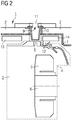
- X-ray source 1 comprises a radiator housing 2, in which an X-ray tube 3 is arranged, which comprises a vacuum housing 4.
- a cathode and a rotary anode 5 are arranged in the vacuum housing 4.
- the cathode is in the chosen representation in FIG. 2 not visible.
- the rotary anode 5 is rotationally mounted on a driven anode shaft 6.
- deflection coils 13 and 14 are arranged in the region of the rotary anode 5 on the inside of the radiator housing 2.
- the deflection coils 13 and 14 serve to deflect the electrons emitted by the cathode in the direction of the rotary anode 5.
- the radiator housing 2 circulates a liquid cooling medium 7 in order to dissipate the heat generated during operation reliably.
- the radiator housing 2 at least in the radiation exit region 11 on at least one inner wall at least one burst protection element 12.
- the radiation exit region 11 comprises a region in which the x-ray radiation generated in the material of the rotary anode 5 exits the radiation exit window 8 in the vacuum housing 4 and enters the radiator housing 2, in order then to exit through the radiation exit window 9 in the radiator housing 2 and thus out of the x-ray emitter 1.
- the burst protection element 12 is an additional component, which is preferably made of a metal and is fastened in a force-locking manner near the region of the radiation outlet window 9 in the radiator housing 2 on the inner wall of the radiator housing 2.
- the burst protection element 12 is thus arranged in the radiation exit region 11 between the vacuum housing 4 and the radiator housing 2.
- Suitable non-positive fasteners are e.g. Can be realized by means of screws, pressure clamps or cable ties.
- the burst protection element 12 is arranged so that incident fragments of the ruptured rotary anode 5 are not directed in the direction of the radiation exit region 11 but in the direction of the thick-walled radiator housing 2.
- This direction represents a so-called deformation path, in which further components are arranged, for example the deflection coils 13 and 14 for deflecting the electrons emitted by the cathode.
- the burst protection element 12 is arranged in the illustrated embodiment.
Landscapes
- X-Ray Techniques (AREA)
Priority Applications (2)
| Application Number | Priority Date | Filing Date | Title |
|---|---|---|---|
| EP18167566.1A EP3557954A1 (fr) | 2018-04-16 | 2018-04-16 | Émetteur de rayons x |
| PCT/EP2019/055656 WO2019201507A1 (fr) | 2018-04-16 | 2019-03-07 | Émetteur de rayons x |
Applications Claiming Priority (1)
| Application Number | Priority Date | Filing Date | Title |
|---|---|---|---|
| EP18167566.1A EP3557954A1 (fr) | 2018-04-16 | 2018-04-16 | Émetteur de rayons x |
Publications (1)
| Publication Number | Publication Date |
|---|---|
| EP3557954A1 true EP3557954A1 (fr) | 2019-10-23 |
Family
ID=62002570
Family Applications (1)
| Application Number | Title | Priority Date | Filing Date |
|---|---|---|---|
| EP18167566.1A Withdrawn EP3557954A1 (fr) | 2018-04-16 | 2018-04-16 | Émetteur de rayons x |
Country Status (2)
| Country | Link |
|---|---|
| EP (1) | EP3557954A1 (fr) |
| WO (1) | WO2019201507A1 (fr) |
Citations (5)
| Publication number | Priority date | Publication date | Assignee | Title |
|---|---|---|---|---|
| DE7715604U1 (de) * | 1977-05-16 | 1978-11-02 | Siemens Ag, 1000 Berlin Und 8000 Muenchen | Röntgenröhren-Schutzgehäuse |
| JPS57136200U (fr) * | 1981-02-20 | 1982-08-25 | ||
| DE102013210967A1 (de) | 2013-06-12 | 2014-12-18 | Siemens Aktiengesellschaft | Röntgenstrahler |
| EP3264441A1 (fr) * | 2015-02-27 | 2018-01-03 | Toshiba Electron Tubes & Devices Co., Ltd. | Dispositif de tube à rayons x |
| DE102016213336A1 (de) * | 2016-07-21 | 2018-01-25 | Siemens Healthcare Gmbh | Röntgenstrahler |
Family Cites Families (2)
| Publication number | Priority date | Publication date | Assignee | Title |
|---|---|---|---|---|
| JP2008084697A (ja) * | 2006-09-27 | 2008-04-10 | Toshiba Corp | 回転陽極x線管装置 |
| JP5405178B2 (ja) * | 2009-04-08 | 2014-02-05 | 株式会社東芝 | 回転陽極型x線管装置 |
-
2018
- 2018-04-16 EP EP18167566.1A patent/EP3557954A1/fr not_active Withdrawn
-
2019
- 2019-03-07 WO PCT/EP2019/055656 patent/WO2019201507A1/fr not_active Ceased
Patent Citations (5)
| Publication number | Priority date | Publication date | Assignee | Title |
|---|---|---|---|---|
| DE7715604U1 (de) * | 1977-05-16 | 1978-11-02 | Siemens Ag, 1000 Berlin Und 8000 Muenchen | Röntgenröhren-Schutzgehäuse |
| JPS57136200U (fr) * | 1981-02-20 | 1982-08-25 | ||
| DE102013210967A1 (de) | 2013-06-12 | 2014-12-18 | Siemens Aktiengesellschaft | Röntgenstrahler |
| EP3264441A1 (fr) * | 2015-02-27 | 2018-01-03 | Toshiba Electron Tubes & Devices Co., Ltd. | Dispositif de tube à rayons x |
| DE102016213336A1 (de) * | 2016-07-21 | 2018-01-25 | Siemens Healthcare Gmbh | Röntgenstrahler |
Also Published As
| Publication number | Publication date |
|---|---|
| WO2019201507A1 (fr) | 2019-10-24 |
Similar Documents
| Publication | Publication Date | Title |
|---|---|---|
| WO2019052922A1 (fr) | Ensemble lidar avec refroidissement par flux d'air | |
| DE3840398A1 (de) | Drehanoden-roentgenroehre | |
| DE212014000043U1 (de) | Röntgenstrahlenquelle mit verbesserter Target-Lebensdauer | |
| AT410991B (de) | Verfahren zum zusammenbauen einer rotierenden röntgenröhrenstruktur | |
| EP0021441B1 (fr) | Accélérateur d'électrons pour radiothérapie aux rayons X | |
| EP2283508B1 (fr) | Source de rayonnement et procédé pour générer des rayons x | |
| EP3793330A1 (fr) | Émetteur de rayons x | |
| DE102014205393A1 (de) | CT-System | |
| EP3629361B1 (fr) | Émetteur de rayons x, emploi d'un émetteur de rayons x et procédé de fabrication d'un émetteur de rayons x | |
| DE102004056110A1 (de) | Drehkolben-Röntgenstrahler | |
| EP3984046B1 (fr) | Système de refroidissement de cuve de réacteur sous pression | |
| DE102012221638B4 (de) | Röntgenstrahler | |
| WO2019201507A1 (fr) | Émetteur de rayons x | |
| DE102006060135A1 (de) | Struktur zum Einfangen von gestreuten Elektronen | |
| DE102017216059A1 (de) | Stehanode für einen Röntgenstrahler und Röntgenstrahler | |
| DE102016213336B4 (de) | Röntgenstrahler | |
| DE10040424A1 (de) | Vorrichtung und Verfahren zur Erhöhung der Röntgenröhrenleistung pro thermischer Last eines Targets | |
| EP1477991B1 (fr) | Enceinte de protection contre les rayonnements pour un appareil à rayons X | |
| DE102005018342B4 (de) | Vorrichtung und Verfahren zur Erzeugung von Röntgenstrahlung | |
| DE202008016905U1 (de) | Vakuumpumpe | |
| DE102013223787A1 (de) | Röntgenröhre | |
| DE202021103476U1 (de) | Modulare Kathodeneinrichtung mit einem Schachtblech | |
| DE69621894T2 (de) | Röntgenröhre und Barrierevorrichtung dafür | |
| DE202017003263U1 (de) | Röntgenröhre | |
| DE102018120215A1 (de) | Röntgengenerator |
Legal Events
| Date | Code | Title | Description |
|---|---|---|---|
| PUAI | Public reference made under article 153(3) epc to a published international application that has entered the european phase |
Free format text: ORIGINAL CODE: 0009012 |
|
| AK | Designated contracting states |
Kind code of ref document: A1 Designated state(s): AL AT BE BG CH CY CZ DE DK EE ES FI FR GB GR HR HU IE IS IT LI LT LU LV MC MK MT NL NO PL PT RO RS SE SI SK SM TR |
|
| AX | Request for extension of the european patent |
Extension state: BA ME |
|
| STAA | Information on the status of an ep patent application or granted ep patent |
Free format text: STATUS: THE APPLICATION IS DEEMED TO BE WITHDRAWN |
|
| 18D | Application deemed to be withdrawn |
Effective date: 20200603 |