EP3558182B1 - Ohrstöpsel und verfahren zur schalldämpfung - Google Patents
Ohrstöpsel und verfahren zur schalldämpfung Download PDFInfo
- Publication number
- EP3558182B1 EP3558182B1 EP17825628.5A EP17825628A EP3558182B1 EP 3558182 B1 EP3558182 B1 EP 3558182B1 EP 17825628 A EP17825628 A EP 17825628A EP 3558182 B1 EP3558182 B1 EP 3558182B1
- Authority
- EP
- European Patent Office
- Prior art keywords
- resonance
- canal
- volume
- mesh
- sound
- Prior art date
- Legal status (The legal status is an assumption and is not a legal conclusion. Google has not performed a legal analysis and makes no representation as to the accuracy of the status listed.)
- Active
Links
Images


Classifications
-
- A—HUMAN NECESSITIES
- A61—MEDICAL OR VETERINARY SCIENCE; HYGIENE
- A61F—FILTERS IMPLANTABLE INTO BLOOD VESSELS; PROSTHESES; DEVICES PROVIDING PATENCY TO, OR PREVENTING COLLAPSING OF, TUBULAR STRUCTURES OF THE BODY, e.g. STENTS; ORTHOPAEDIC, NURSING OR CONTRACEPTIVE DEVICES; FOMENTATION; TREATMENT OR PROTECTION OF EYES OR EARS; BANDAGES, DRESSINGS OR ABSORBENT PADS; FIRST-AID KITS
- A61F11/00—Methods or devices for treatment of the ears or hearing sense; Non-electric hearing aids; Methods or devices for enabling ear patients to achieve auditory perception through physiological senses other than hearing sense; Protective devices for the ears, carried on the body or in the hand
- A61F11/06—Protective devices for the ears
- A61F11/08—Protective devices for the ears internal, e.g. earplugs
-
- A—HUMAN NECESSITIES
- A61—MEDICAL OR VETERINARY SCIENCE; HYGIENE
- A61F—FILTERS IMPLANTABLE INTO BLOOD VESSELS; PROSTHESES; DEVICES PROVIDING PATENCY TO, OR PREVENTING COLLAPSING OF, TUBULAR STRUCTURES OF THE BODY, e.g. STENTS; ORTHOPAEDIC, NURSING OR CONTRACEPTIVE DEVICES; FOMENTATION; TREATMENT OR PROTECTION OF EYES OR EARS; BANDAGES, DRESSINGS OR ABSORBENT PADS; FIRST-AID KITS
- A61F11/00—Methods or devices for treatment of the ears or hearing sense; Non-electric hearing aids; Methods or devices for enabling ear patients to achieve auditory perception through physiological senses other than hearing sense; Protective devices for the ears, carried on the body or in the hand
- A61F11/06—Protective devices for the ears
- A61F11/08—Protective devices for the ears internal, e.g. earplugs
- A61F11/085—Protective devices for the ears internal, e.g. earplugs including an inner channel
Definitions
- the present invention relates to an earplug as defined in claims 1-11 and a method for attenuating sound as defined in claim 12.
- Earplugs provide a simple way to dampen sound from an outside surroundings to an ear canal.
- Acoustic attenuation can be achieved for example by an acoustic dampening element such as a membrane or mesh disposed in an acoustic canal through the earplug.
- a mesh has a desired property that it can allow ventilation or equilibration of air and water there through.
- the acoustic transfer function of a mesh typically shows increasing attenuation at higher frequencies. This may be perceived by the user as an occlusion effect, which is undesirable.
- Excessive dampening at high frequencies can be (partially) compensated by providing a canal with a specifically tuned resonance frequency.
- a canal with a specifically tuned resonance frequency.
- the canal may be folded, but this may leads to a more complicated construction and less adaptability, e.g. tuning of the resonance to a specific user.
- creating a resonance at one frequency can have the effect of even further lowering sound levels at adjacent frequencies.
- EP1046382A1 describes a sound damping filter comprising a sound damping canal with a passage closed off by means of an air-permeable sheetlike membrane
- WO01/76520A1 describes an earplug with a through duct, in which a membrane element is adapted and comprises a membrane holder and a membrane held thereby which is adapted to lock the membrane element.
- the earplug comprises a housing with an ear tip configured to form an acoustic seal with the ear canal.
- An acoustic canal extends straight through the housing to guide the sound from the outside surroundings to inside the ear canal.
- the acoustic canal comprises a canal section having a first diameter that is dimensioned to fit at least partially inside the ear canal.
- the canal section ends at one side in a first exterior opening that is in use directed to let the sound through the earplug into the ear canal. Another side of the canal section transitions into a first resonance volume.
- the first resonance volume starts from an end of the canal section with a second diameter that is wider than the first diameter.
- the acoustic canal further comprises a second resonance volume ending at one side in a second exterior opening.
- the second exterior opening is in use directed to the outside surroundings for receiving the sound.
- Another side of the second resonance volume is separated from the first resonance volume by a sound attenuating mesh bounding one side of each of the resonance volumes.
- the resonance volumes form part of respective resonance cavities separated by the mesh.
- the resonance cavities provide resonance peaks that (partially) compensate attenuation of the mesh in a resonance frequencies range above one kilohertz.
- the earplug can be of relatively simple construction.
- the straight canal may also provide less frequency dependence compared to a folded canal and also improve ventilation of the ear canal in combination with the mesh.
- the combination may act similar to a Helmholtz resonator wherein the resonance frequency can be decreased by increasing the volume rather than extending the length of the canal. In this way the earplug can be more compact without requiring a complicated channel.
- the resonance can also be easily tuned by adapting the volume without having to extend a length of the earplug.
- a distinct resonance peak can be achieved which extends the frequency range for compensating the mesh attenuation above one kilohertz.
- each cavity is bounded while at the same time providing attenuation through the acoustic canal.
- This further simplifies construction.
- This secondary resonance volume might be placed in the concha of the ear, thus filling the concha opening partially.
- Optional openings to the circumference of the secondary resonance volume may improve directional hearing, thus further improving the acoustic properties of the earplug. All features combined may thus provide a compact ventilating earplug of simple construction which provides attenuated sound with minimal occlusion effect over an extended range of frequencies.
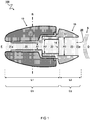
- FIG 1 schematically illustrates a cross-sectional view of an embodiment for an earplug 100 for attenuating sound S from an outside surroundings O to an ear canal E.
- the earplug 100 comprises a housing 10 with an ear tip 11 configured to form an acoustic seal B with the ear canal E.
- An acoustic canal 20 extends through the housing 10 to guide the sound S from the outside surroundings O to inside the ear canal E.
- the acoustic canal 20 comprises a canal section 21 having a first diameter A1 that is dimensioned to fit at least partially inside the ear canal.
- the canal section 21 ends at one side in a first exterior opening 21a that is in use directed to let the sound S into the ear canal.
- Another side of the canal section 21 transitions into a first resonance volume 22.
- the first resonance volume 22 may be defined as starting from an end of the canal section 21 at a position of a second diameter A2 where it gets wider than the first diameter A1.
- the canal section 21 is a straight canal between the ear canal E and the first resonance volume 22.
- the canal section 21 is typically formed by a relatively narrow first tubular part 12 extending partially through the housing 10.
- the first tubular part 12 is covered by an exterior part forming the ear tip 11.
- the ear tip 11 comprises a flexible exterior configured to adapt to its form to an entry of the ear canal E, e.g. a viscoelastic tip.
- the ear tip 11 comprises thermoplastic elastomer TPE or silicone.
- the ear tip 11 comprises a custom molded earplug, e.g. otoplastics.
- the canal section 21, first resonance volume 22, and/or second resonance volume 23 have a cylindrical shape.
- the cylindrical sections line up along a straight line through the earplug, e.g. having a common central axis.
- other shapes may be used, e.g. elliptical, square triangular, etcetera, and/or the central axis may be shifted between sections.
- the first resonance volume 22 and/or second resonance volume 23 is formed in a relatively wide second tubular part 13. These parts can be wider because they need not fit in the ear canal.
- the second tubular part 13 forms the second resonance volume 23 as an open volume with the second exterior opening 23a configured to catch sound S from the outside surroundings O and guide them into the earplug 100.
- the second resonance volume 23 is formed by a surrounding mantle section ending at one side with the mesh 14 and at the opposite side in an opening to the outside surroundings O.
- the mantle section comprises one or more additional side openings.
- the side openings can be holes in the mantle section or slits extending from the central opening 23a into the mantle section. The holes at the side may allow sound to enter, e.g. bouncing from the concha of the ear, to improve directional hearing of a user wearing the ear plug.
- the earplug comprises a sound attenuating element, such as a mesh or mesh-like structure 14 in the acoustic canal 20.
- the mesh may comprise any sound attenuating surface or foil with a structure defining microscopic holes distributed over the surface for filtering sound waves there through.
- the microscopic holes or slits typically have a small cross-section diameter, preferably less than two hundred micrometer, e.g. between ten and hundred micrometer.
- precision woven meshes for use in acoustic applications can be made wires woven together.
- mesh-like structures may be produced by injection molding, e.g. comprising micro-slits or holes.
- the mesh is typically made of strong nylon, metal, PE or PET. After providing the mesh in the desired dimensions, it is typically connected to a carrier part such as the second tubular part 13 to give it support.
- a connection between the mesh and the carrier may comprise gluing, ultrasonic welding or injection molding the part around the mesh.
- the second tubular part 13 may be constructed as one piece integral with the mesh 14, e.g. by molding the part together with the mesh.
- a surface of the mesh is transverse to a length of the acoustic canal 20.
- the mesh 14 can be tilted, e.g. wherein a normal vector to a surface of the mesh is at an angle with respect to a centerline of the acoustic canal 20. Tilting the mesh at an oblique angle may increase its effective surface e.g. for exchange of water and air there through.
- the mesh can be tilted by at least twenty degrees, e.g. wherein the normal vector of the mesh surface is at an angle between forty and sixty degrees with respect to the centerline of the acoustic canal.
- the second tubular part 13 comprises the mesh 14 separating the first resonance volume 22 and second resonance volume 23.
- the mesh 14 can also be provided elsewhere.
- the acoustic canal 20 comprises an optional second resonance volume 23 ending at one side in a second exterior opening 23a.
- the second exterior opening 23a is in use directed to the outside surroundings for receiving the sound S.
- the second exterior opening 23a faces in an opposite direction with respect to the first exterior opening 21a.
- the acoustic canal 20 is directed along a straight line between the second exterior opening 23a and the oppositely facing first exterior opening 21a.
- the second resonance volume 23 may be separated from the first resonance volume 22 by the sound attenuating mesh 14. Accordingly, the mesh 14 can act as a boundary at one side of each of the resonance volumes 22,23. In this way the resonance volumes 22,23 may form part of respective resonance cavities C1, C2 separated by the mesh 14.
- a combined length L1 of the canal section 21 and first resonance volume 22 is between one and two centimeters.
- the length L1, measured between the mesh 14 and an edge of the first exterior opening 21a is less than twenty millimeters, preferably less than eighteen or sixteen millimeters.
- the canal section is preferably narrow to fit in the ear canal.
- the canal section 21 has a diameter A1 in a range between one and five millimeters, preferably between one-and half and four millimeters, or between two and three millimeters.
- the canal section 21 is relatively short to provide a compact earplug yet long enough to fit with sufficient length in the ear canal.
- the canal section 21 has a length in a range between five and twelve millimeters, preferably between eight and eleven millimeters.
- the first resonance volume 22 is defined between the mesh 14 up to but not including the canal section 21.
- a diameter A2 of the first resonance volume 22 is preferably larger than a diameter A1 of the canal section 21, e.g. at least by a factor one-and-half, two, two-and-half, or more, e.g. up to a factor three, four, or five.
- the first resonance volume 22 has a diameter A2 in a range between three-and-half and five-and-half: millimeters, preferably between four and five millimeters, e.g. four-and-half millimeter.
- a cross-sectional area of the first resonance volume 22 is larger than a cross-sectional area of the canal section 21, e.g. by a factor two, three, four, five, or more.
- a volume of the first resonance volume 22 is larger than a volume of the canal section 21, e.g. by a factor of one-and-half, two, or more, e.g. up to a factor three or four.
- the first resonance volume 22 is preferably between thirty and hundred fifty cubic millimeters, e.g. more than fifty cubic millimeters.
- the second resonance volume 23 is defined between the mesh 14 up to the edge of the second exterior opening 23a.
- the second resonance volume 23 has a diameter A3 that is even larger than a diameter A2 of the first resonance volume 22, e.g. larger by a factor 1.1 or 1.2, or more, e.g. up to a factor 1.5.
- the larger diameter may provide a relatively large entry for receiving sound S.
- the second resonance volume 23 has a diameter A3 in a range between 4,5 and 6.5 millimeters, preferably between five and six millimeters, e.g. five-and-half millimeters.
- the second resonance volume 23 can also be relatively large, e.g. with a volume between hundred and two hundred cubic millimeters, e.g.
- the second resonance volume 23 may be larger than the first resonance volume 22, e.g. by a factor 1.2, 1.3, or more, e.g. up to a factor two. It is noted that the larger diameter A3 at the exterior opening 23a may cause a relatively higher resonance frequency.
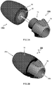
- FIG 2A schematically illustrates an isometric view of an embodiment for the earplug comprising two parts.
- FIG 2B schematically illustrates the parts brought together to form the ear plug.
- the earplug 100 comprises at least two parts 100a, 100b fitting together.
- the first part 100a of the earplug comprises a first tubular part 12 covered at its outer hull by material forming the ear tip 11.
- the second part 100b of the ear plug may comprise a second tubular part 13, wherein the first tubular part 12 and the second tubular part 13 fit together.
- a shape fitting wherein the outer diameter of a section of the second tubular part 13 is slightly higher than the inner diameter of the corresponding section of the first tubular part 12.
- the first tubular part 12 can have a widened section configured to receive a section of the second tubular part 13 forming the first resonance volume 22.
- the fitting parts may be reversed, e.g. a part of the first part 100a of the earplug can fit into the second part 100b of the ear plug.
- the second part 100b of the ear plug comprise a finger gripping portion with two, three, or more depressions to facilitate gripping the ear plug with two, three, or more finger.
- two parts of the earplug fit together with a controllable distance defining a variable volume of the first resonance cavity C1.
- the resonance frequency may be tuned.
- the parts may fit together with a bayonet or screw connection (not shown) wherein a turning of one part with respect to the other determines the resonance volume and frequency.
- a simple sliding connection can be provided, e.g. wherein the parts fit tightly together.
- FIG 3 shows model calculations of frequency (F) dependent (relative) sound levels ( ⁇ S) to illustrate effects provided by different parts forming the earplug.
- FIGs 4A-4E illustrate the parts or embodiments of an earplug used in the model calculations of FIG 3 .
- Curve 30a illustrates a modelled open ear response of a human ear without earplug. See also FIG 4A .
- the curve shows a natural resonance peak Roo extending approximately between one and four kilohertz. Such resonance may typically depend on the shape and dimensions of the ear canal. In some cases the resonance can be useful in emphasizing some higher frequencies that may be part of human speech.
- Curve 30b illustrates a modelled response of attenuation provided by only the mesh 14. See also FIG 4B .
- the mesh 14 provides lowering sound levels (or increasing attenuation - ⁇ S) for increasing frequencies F.
- the mesh 14 is configured to provide sufficient attenuation of the sound S at two hundred Hertz ⁇ S 200 between ten and twenty-five decibel.
- the mesh 14 is configured to provide attenuation of the sound S at one kilohertz ⁇ S 1K between twenty and thirty five decibel.
- Curve 30c illustrates a modelled response of attenuation provided by the mesh 14 in combination with only a straight canal section 21. See also FIG 4C . Comparing curves 30b and 30c illustrates that addition of the canal section 21 causes a resonance peak R0 which partially compensates attenuation of the mesh 14 but at relatively high frequencies above five kilohertz.
- Curve 30d illustrates a modelled response of attenuation provided by the mesh 14 in combination with the first resonance cavity C1 formed by the canal section 21 and the first resonance volume 22. See also FIG 4D . Comparing curves 30c and 30d illustrates that addition of the first resonance volume 22 to the canal section 21 has the effect of shifting the resonance peak of the combined first resonance cavity C1 from an original peak R0 to a shifted peak R1 at a lower frequency.
- the position of the first resonance peak R1 may be controlled by adapting the volume of the first resonance volume 22, e.g. with a larger volume or wider cross-section section A2 resulting in a lower frequency of the first resonance peak R1. In this way, an overall length of the earplug can be kept within a desired range.
- the position of the first resonance peak R1 may also be controlled by adapting a length of the canal section 21, e.g. with a longer canal resulting in a lower frequency of the first resonance peak R1. However this may lead to a long canal and too large ear plug for the desired frequency shift.
- this construction provides desired compensation for attenuation of the mesh 14 at frequencies between one and four kilohertz. However, it is noted that the sound level may actually be decreased for frequencies above four kilohertz.
- Curve 30e illustrates a modelled response of attenuation provided by the mesh 14 in combination with the first resonance cavity C1 and the second resonance cavity C2 formed by the second resonance volume 23. See also FIG 4E . Comparing curves 30d and 30e illustrates that addition of the second resonance volume 23 has the effect of increasing the sound levels or decreasing the attenuation also at higher frequencies, e.g. between four and ten kilohertz. Accordingly, the attenuation of the mesh 14 may be partially compensated over a relatively wide range of frequencies.
- the resonance cavities C1, C2 of the earplug can provide resonance peaks R1,R2 that at least partially compensate attenuation of the mesh 14.
- the sound S is less attenuated around the resonance peaks R1,R2 than it would be in absence of the resonance cavities.
- the acoustic canal can be configured to provide at least two distinct resonance peaks R1,R2 that partially counteract attenuation - ⁇ S of the sound S by the mesh 14 in respective frequency ranges around the resonance peaks R1,R2.
- the compensation takes place in a resonance frequencies range Fr above one kilohertz.
- the maxima of the resonance peaks R1,R2 are in a frequency range Fr above two kilohertz, preferably above three kilohertz.
- the maxima of the resonance peaks R1,R2 are in a frequency range Fr below ten kilohertz, preferably below nine kilohertz.
- the maxima of the resonance peaks R1,R2 are at least two kilohertz apart, preferably at least three or four kilohertz. Furthermore, it is preferably that each of the resonance peaks R1,R2 covers a relatively wide range. For example a full width of the resonance peak at -6 dB from its maximum is at least five hundred hertz, preferably more than one kilohertz.
- the resonance frequencies may cover a range at least between two and six kilohertz, preferably a wider range, e.g. between one kilohertz up to seven, eight, nine, or ten kilohertz. Accordingly, the resonance peaks R1,R2 are adapted to lower high-frequency attenuation of the sound S above one kilohertz.
- the sound level is relatively constant over a range of frequencies.
- a difference between attenuation of sound S at two kilohertz - ⁇ S 2K compared to attenuation at one kilohertz - ⁇ S 1K is less than five decibel [dB], preferably less than four or three decibel.
- the canal section 21 and the first resonance volume 22 are configured to form, in combination, a first resonance cavity C1 with a first resonance peak R1 for the sound S in a first frequency range F1 between two and five kilohertz, preferably between three and four kilohertz.
- the first resonance cavity C1 is adapted to create the first resonance peak R1 just above a resonance Roo of an open ear response 30a.
- the second resonance volume 23 is configured to form a second resonance cavity C2 with a second resonance peak R2 for the sound S in a second frequency range F2 between five and ten kilohertz, preferably between six and nine kilohertz.
- the figures illustrate an earplug 100 and corresponding method for attenuating sound S from an outside surroundings O to an ear canal E.
- a housing 10 is provided with an ear tip 11 to form an acoustic seal B with the ear canal E.
- An acoustic canal 20 extends straight through the housing 10 to guide the sound S from the outside surroundings O to inside the ear canal E.
- the acoustic canal 20 comprises a canal section 21 having a first diameter A1 that fits at least partially inside the ear canal.
- the canal section 21 ends at one side in a first exterior opening 21a that lets the sound S into the ear canal.
- the acoustic canal 20 further comprises a second resonance volume 23 ending at one side in a second exterior opening 23a that receives the sound S.
- Another side of the second resonance volume 23 is separated from the first resonance volume 22 by a sound attenuating mesh 14 bounding one side of each of the resonance volumes 22,23.
- the resonance volumes 22,23 may form part of respective resonance cavities C1, C2 separated by the mesh 14.
- the resonance cavities C1, C2 can thus provide resonance peaks R1,R2 that partially compensate attenuation of the mesh 14 in a resonance frequencies range Fr, e.g. above one kilohertz.
Landscapes
- Health & Medical Sciences (AREA)
- Life Sciences & Earth Sciences (AREA)
- Biomedical Technology (AREA)
- Acoustics & Sound (AREA)
- Biophysics (AREA)
- Otolaryngology (AREA)
- Psychology (AREA)
- Engineering & Computer Science (AREA)
- Physics & Mathematics (AREA)
- Heart & Thoracic Surgery (AREA)
- Vascular Medicine (AREA)
- Animal Behavior & Ethology (AREA)
- General Health & Medical Sciences (AREA)
- Public Health (AREA)
- Veterinary Medicine (AREA)
- Headphones And Earphones (AREA)
Claims (12)
- Ohrstöpsel (100) zum Dämpfen von Schall (S) von einer äußeren Umgebung (O) zu einem Gehörgang (E), wobei der Ohrstöpsel (100) umfasst- ein Gehäuse (10) mit einer Ohrspitze (11), die so konfiguriert ist, dass sie eine akustische Abdichtung (B) mit dem Gehörgang (E) bildet; und- einen akustischen Kanal (20), der sich gerade durch das Gehäuse (10) erstreckt, um den Schall (S) von der äußeren Umgebung (O) in das Innere des Gehörgangs (E) zu leiten, wobei der akustische Kanal (20) umfassto einen Kanalabschnitt (21) mit einem ersten Durchmesser (A1), der so dimensioniert ist, dass er wenigstens teilweise in den Gehörgang passt, wobei der Kanalabschnitt (21) an einer Seite in einer ersten äußeren Öffnung (21a) endet, die im Gebrauch so ausgerichtet ist, dass sie den Schall (S) in den Gehörgang einlässt, wobei eine andere Seite des Kanalabschnitts (21) übergeht ino ein erstes Resonanzvolumen (22), das an einem Ende des Kanalabschnitts (21) mit einem zweiten Durchmesser (A2) beginnt, der breiter als der erste Durchmesser (A1) ist; wobei der akustische Kanal (20) ferner umfasst∘ ein zweites Resonanzvolumen (23), das an einer Seite in einer zweiten äußeren Öffnung (23a) endet, die im Gebrauch zur äußeren Umgebung gerichtet ist, um den Schall (S) zu empfangen, wobei eine andere Seite des zweiten Resonanzvolumens (23) von dem ersten Resonanzvolumen (22) getrennt ist durch∘ ein schalldämpfendes Netz (14), das jeweils eine Seite der Resonanzvolumen (22,23) begrenzt;wobei der akustische Kanal (20) entlang einer geraden Linie zwischen der zweiten äußeren Öffnung (23a) und der entgegengesetzt gerichteten ersten äußeren Öffnung (21a) gerichtet ist;
wobei eine kombinierte Länge (L1) des Kanalabschnitts (21) und des ersten Resonanzvolumens (22), gemessen zwischen dem Netz (14) und einer Kante der ersten äußeren Öffnung (21a), zwischen einem und zwei Zentimetern liegt; wobei ein Volumen des ersten Resonanzvolumens (22) größer ist als ein Volumen des Kanalabschnitts (21);
wobei der Kanalabschnitt (21) und das erste Resonanzvolumen (22) so konfiguriert sind, dass sie in Kombination einen ersten Resonanzhohlraum (C1) mit einer ersten Resonanzspitze (R1) für den Schall (S) in einem ersten Frequenzbereich (F1) zwischen zwei und fünf Kilohertz bilden;
wobei das zweite Resonanzvolumen (23) so konfiguriert ist, dass es einen zweiten Resonanzhohlraum (C2) mit einer zweiten Resonanzspitze (R2) für den Schall (S) in einem zweiten Frequenzbereich (F2) zwischen fünf und zehn Kilohertz bildet;
wobei die Hohlräume (C1, C2) durch das Netz (14) getrennt sind;
wobei erste und zweite Resonanzspitzen (R1,R2) die Dämpfung des Netzes (14) in einem Resonanzfrequenzbereich (Fr) über einem Kilohertz teilweise kompensieren. - Ohrstöpsel nach einem der vorhergehenden Ansprüche, wobei der Ohrstöpsel zwei Teile (100a, 100b) umfasst, die mit einem steuerbaren Abstand zusammenpassen, der ein variables Volumen des ersten Resonanzhohlraums (C1) definiert.
- Ohrstöpsel nach einem der vorhergehenden Ansprüche, wobei der akustische Kanal so konfiguriert ist, dass er wenigstens zwei verschiedene Resonanzspitzen (R1, R2) bereitstellt, die teilweise der Dämpfung (-ΔS) des Schalls (S) durch das Netz (14) in den jeweiligen Frequenzbereichen um die Resonanzspitzen (R1, R2) herum entgegenwirken.
- Ohrstöpsel nach einem der vorhergehenden Ansprüche, wobei die Maxima der Resonanzspitzen (R1, R2) wenigstens zwei Kilohertz voneinander entfernt sind.
- Ohrstöpsel nach einem der vorhergehenden Ansprüche, wobei der von den Resonanzspitzen (R1, R2) bereitgestellte Resonanzfrequenzbereich (Fr) einen Bereich von wenigstens zwischen zwei und acht Kilohertz abdeckt, in dem die Dämpfung des Netzes (14) wenigstens teilweise kompensiert wird.
- Ohrstöpsel nach einem der vorhergehenden Ansprüche, wobei die kombinierte Länge (L1) des Kanalabschnitts (21) und des ersten Resonanzvolumens (22), gemessen zwischen dem Netz (14) und der Kante der ersten äußeren Öffnung (21a), weniger als siebzehn Millimeter beträgt.
- Ohrstöpsel nach einem der vorhergehenden Ansprüche, wobei ein Durchmesser (A2) des ersten Resonanzvolumens (22) um einen Faktor eineinhalb oder mehr größer ist als ein Durchmesser (A1) des Kanalabschnitts (21).
- Ohrstöpsel nach einem der vorhergehenden Ansprüche, wobei das Volumen des ersten Resonanzvolumens (22) um den Faktor eineinhalb oder mehr größer als das Volumen des Kanalabschnitts (21) ist.
- Ohrstöpsel nach einem der vorhergehenden Ansprüche, wobei eine Normale des Netzes (14) in einem Winkel in Bezug auf eine Mittellinie des akustischen Kanals (20) geneigt ist, um seine wirksame Oberfläche zu vergrößern.
- Ohrstöpsel nach einem der vorhergehenden Ansprüche, wobei das zweite Resonanzvolumen (23) durch einen umgebenden Mantelabschnitt gebildet wird, der an einer Seite mit dem Netz (14) und an der gegenüberliegenden Seite in einer Öffnung zur äußeren Umgebung (O) endet, wobei der Mantelabschnitt eine oder mehrere zusätzliche Seitenöffnungen zur Verbesserung des Richtungshörens in der Umgebung umfasst.
- Ohrstöpsel nach einem der vorhergehenden Ansprüche, wobei der Kanalabschnitt (21) durch einen relativ schmalen ersten röhrenförmigen Teil (12) gebildet wird, der von einem flexiblen Äußeren bedeckt ist, das so konfiguriert ist, dass es seine Form an einen Eingang des Gehörgangs (E) anpasst, wobei das erste Resonanzvolumen (22) und/oder das zweite Resonanzvolumen (23) in einem relativ breiten zweiten röhrenförmigen Teil (13) gebildet werden, wobei der zweite röhrenförmige Teil (13) das Netz (14) umfasst, das das erste Resonanzvolumen (22) und das zweite Resonanzvolumen (23) trennt, wobei der erste und der zweite röhrenförmige Teil (11,12) zusammenpassen, um den Ohrstöpsel zu bilden.
- Verfahren zum Dämpfen von Schall (S) aus einer äußeren Umgebung (O) in einen Gehörgang (E), wobei das Verfahren einen Schritt des Bereitstellens eines Ohrstöpsels für den Gehörgang umfasst, wobei der Ohrstöpsel umfasst:- ein Gehäuse (10) mit einer Ohrspitze (11) zur Bildung einer akustischen Abdichtung (B) mit dem Gehörgang (E); und- einen akustischen Kanal (20), der sich gerade durch das Gehäuse (10) erstreckt, um den Schall (S) von der äußeren Umgebung (O) in das Innere des Gehörgangs (E) zu leiten, wobei der akustische Kanal (20) umfassto einen Kanalabschnitt (21) mit einem ersten Durchmesser (A1), der wenigstens teilweise in den Gehörgang passt, wobei der Kanalabschnitt (21) an einer Seite in einer ersten äußeren Öffnung (21a) endet, die den Schall (S) in den Gehörgang einlässt, wobei eine andere Seite des Kanalabschnitts (21) übergeht in∘ ein erstes Resonanzvolumen (22), das an einem Ende des Kanalabschnitts (21) mit einem zweiten Durchmesser (A2) beginnt, der breiter ist als der erste Durchmesser (A1); der akustische Kanal (20) umfasst ferner∘ ein zweites Resonanzvolumen (23), das an einer Seite in einer zweiten äußeren Öffnung (23a) endet, die den Schall (S) empfängt, wobei eine andere Seite des zweiten Resonanzvolumens (23) von dem ersten Resonanzvolumen (22) getrennt ist durcho ein schalldämpfendes Netz (14), das jeweils eine Seite der Resonanzvolumen (22,23) begrenzt;wobei der akustische Kanal (20) entlang einer geraden Linie zwischen der zweiten äußeren Öffnung (23a) und der entgegengesetzt gerichteten ersten äußeren Öffnung (21a) gerichtet ist;
wobei eine kombinierte Länge (L1) des Kanalabschnitts (21) und des ersten Resonanzvolumens (22), gemessen zwischen dem Netz (14) und einer Kante der ersten äußeren Öffnung (21a), zwischen einem und zwei Zentimetern liegt;
wobei ein Volumen des ersten Resonanzvolumens (22) größer ist als ein Volumen des Kanalabschnitts (21);
wobei der Kanalabschnitt (21) und das erste Resonanzvolumen (22) so konfiguriert sind, dass sie in Kombination einen ersten Resonanzhohlraum (C1) mit einer ersten Resonanzspitze (R1) für den Schall (S) in einem ersten Frequenzbereich (F1) zwischen zwei und fünf Kilohertz bilden;
wobei das zweite Resonanzvolumen (23) so konfiguriert ist, dass es einen zweiten Resonanzhohlraum (C2) mit einer zweiten Resonanzspitze (R2) für den Schall (S) in einem zweiten Frequenzbereich (F2) zwischen fünf und zehn Kilohertz bildet;
wobei die Resonanzhohlräume (C1, C2) durch das Netz (14) getrennt sind;
wobei die erste und die zweite Resonanzspitze (R1, R2) die Dämpfung des Netzes (14) in einem Resonanzfrequenzbereich (Fr) über einem Kilohertz teilweise kompensieren.
Applications Claiming Priority (2)
| Application Number | Priority Date | Filing Date | Title |
|---|---|---|---|
| NL2018029A NL2018029B1 (en) | 2016-12-20 | 2016-12-20 | Earplug and method for attenuating sound |
| PCT/NL2017/050847 WO2018117821A1 (en) | 2016-12-20 | 2017-12-19 | Earplug and method for attenuating sound |
Publications (2)
| Publication Number | Publication Date |
|---|---|
| EP3558182A1 EP3558182A1 (de) | 2019-10-30 |
| EP3558182B1 true EP3558182B1 (de) | 2021-02-17 |
Family
ID=60935920
Family Applications (1)
| Application Number | Title | Priority Date | Filing Date |
|---|---|---|---|
| EP17825628.5A Active EP3558182B1 (de) | 2016-12-20 | 2017-12-19 | Ohrstöpsel und verfahren zur schalldämpfung |
Country Status (5)
| Country | Link |
|---|---|
| US (1) | US11291586B2 (de) |
| EP (1) | EP3558182B1 (de) |
| CN (1) | CN110290769B (de) |
| NL (1) | NL2018029B1 (de) |
| WO (1) | WO2018117821A1 (de) |
Families Citing this family (5)
| Publication number | Priority date | Publication date | Assignee | Title |
|---|---|---|---|---|
| US11514878B2 (en) * | 2018-02-23 | 2022-11-29 | Purdue Research Foundation | Helmholtz resonators with broadband capability |
| NL2021475B1 (en) * | 2018-08-16 | 2020-02-24 | Elacin Int B V | A sound damping filter for a hearing protector placeable in the auditory duct of a person, as well as a corresponding hearing protector. |
| WO2020121936A1 (ja) * | 2018-12-12 | 2020-06-18 | 株式会社Jvcケンウッド | 耳栓 |
| CA3248282A1 (en) * | 2022-04-13 | 2023-10-19 | École De Technologie Supérieure | OCCLUSION EFFECT REDUCTION DEVICE FOR HEADPHONES |
| EP4618589A1 (de) | 2024-03-13 | 2025-09-17 | Sonova AG | Kompakte akustische vorrichtung mit anpassbarer frequenzregelung |
Family Cites Families (10)
| Publication number | Priority date | Publication date | Assignee | Title |
|---|---|---|---|---|
| JPS6031748A (ja) * | 1983-08-03 | 1985-02-18 | アサオカ株式会社 | 耳栓 |
| US4852683A (en) | 1988-01-27 | 1989-08-01 | Etymotic Research, Inc. | Earplug with improved audibility |
| US5113967A (en) | 1990-05-07 | 1992-05-19 | Etymotic Research, Inc. | Audibility earplug |
| US6148821A (en) * | 1998-04-29 | 2000-11-21 | Cabot Safety Intermediate Corporation | Selective nonlinear attenuating earplug |
| NL1011877C2 (nl) * | 1999-04-23 | 2000-10-24 | Groeneveld Elcea B V | Geluiddempingsfilter, gehoorbeschermer en werkwijze voor het vervaardigen van een membraan voor een geluiddempingsfilter. |
| SE527853C2 (sv) | 2000-04-06 | 2006-06-20 | Bacou Dalloz Ab | Ljuddämpande öronpropp, membranelement placerad i öronproppens genomgående kanal, sätt att tillverka nämnda öronpropp samt sätt att påverka förloppet av öronproppens dämpningskurva |
| US6691822B2 (en) * | 2000-04-28 | 2004-02-17 | Groeneveld Elcea B.V. | Sound damping filter, ear protector, and method for manufacturing a membrane for a sound damping |
| NL2004004C2 (en) | 2009-12-22 | 2011-06-23 | Dynamic Ear Company B V | Ear protector with a sound damping filter, sound damping filter for such an ear protector as well as method for manufacturing a sound damping filter for such an ear protector. |
| FR2965967B1 (fr) | 2010-10-11 | 2013-08-02 | Pascal Roussel | Filtre acoustique a inserer dans un bouchon d'oreille permettant la perception des sons avec une pente d'attenuation de + 2db/octave |
| NL2013208B1 (en) | 2014-07-17 | 2016-07-14 | Dynamic Ear Company B V | Acoustic valve and ear plug for hearing protection. |
-
2016
- 2016-12-20 NL NL2018029A patent/NL2018029B1/en active
-
2017
- 2017-12-19 US US16/471,303 patent/US11291586B2/en active Active
- 2017-12-19 CN CN201780086253.7A patent/CN110290769B/zh active Active
- 2017-12-19 EP EP17825628.5A patent/EP3558182B1/de active Active
- 2017-12-19 WO PCT/NL2017/050847 patent/WO2018117821A1/en not_active Ceased
Non-Patent Citations (1)
| Title |
|---|
| None * |
Also Published As
| Publication number | Publication date |
|---|---|
| CN110290769A (zh) | 2019-09-27 |
| EP3558182A1 (de) | 2019-10-30 |
| US20190321230A1 (en) | 2019-10-24 |
| WO2018117821A1 (en) | 2018-06-28 |
| NL2018029B1 (en) | 2018-06-28 |
| CN110290769B (zh) | 2021-03-09 |
| US11291586B2 (en) | 2022-04-05 |
Similar Documents
| Publication | Publication Date | Title |
|---|---|---|
| US11291586B2 (en) | Earplug and method for attenuating sound | |
| CN109218887B (zh) | 具有通风室的质量加载耳塞 | |
| CN101626745B (zh) | 具有过滤器结构的低减音听力保护装置 | |
| EP2819428B1 (de) | Musikohrhörer | |
| US8565466B2 (en) | Auditory canal earphone | |
| US6068079A (en) | Acoustic valve capable of selective and non-linear filtering of sound | |
| JP2013085310A (ja) | 聴覚保護イヤプラグ | |
| US8107638B2 (en) | Semi-insert hearing protector having a helmholtz-type resonator | |
| WO2021071877A1 (en) | Horn loudspeakers | |
| WO2019010864A1 (zh) | 噪音滤波器及包括其的耳塞 | |
| US20230022343A1 (en) | An earphone with an acoustic rear chamber vent | |
| US20250310679A1 (en) | Method and apparatus for tuned-frequency-spectrum earpiece | |
| US10716710B2 (en) | Method for manufacturing a sealing ring, and a sealing ring | |
| CN117528309A (zh) | 用于耳机的耳垫或耳模以及具有耳垫或耳模的耳机 | |
| US20210243516A1 (en) | Ear tip with wedge-shaped apertures and earpiece with the same | |
| JP2016220165A (ja) | マイクロホン | |
| US20050196004A1 (en) | Ear insert for a hearing aid | |
| CN109767748B (zh) | 一种耳道内分频段调节噪声滤波的主动降噪方法和装置 | |
| TW202315418A (zh) | 包含在耳道內提供可控制緊固機構之經改良耳機墊系統的無線耳機 | |
| JP2007060529A (ja) | 位相反転型スピーカキャビネット |
Legal Events
| Date | Code | Title | Description |
|---|---|---|---|
| STAA | Information on the status of an ep patent application or granted ep patent |
Free format text: STATUS: UNKNOWN |
|
| STAA | Information on the status of an ep patent application or granted ep patent |
Free format text: STATUS: THE INTERNATIONAL PUBLICATION HAS BEEN MADE |
|
| PUAI | Public reference made under article 153(3) epc to a published international application that has entered the european phase |
Free format text: ORIGINAL CODE: 0009012 |
|
| STAA | Information on the status of an ep patent application or granted ep patent |
Free format text: STATUS: REQUEST FOR EXAMINATION WAS MADE |
|
| 17P | Request for examination filed |
Effective date: 20190715 |
|
| AK | Designated contracting states |
Kind code of ref document: A1 Designated state(s): AL AT BE BG CH CY CZ DE DK EE ES FI FR GB GR HR HU IE IS IT LI LT LU LV MC MK MT NL NO PL PT RO RS SE SI SK SM TR |
|
| AX | Request for extension of the european patent |
Extension state: BA ME |
|
| DAV | Request for validation of the european patent (deleted) | ||
| DAX | Request for extension of the european patent (deleted) | ||
| GRAP | Despatch of communication of intention to grant a patent |
Free format text: ORIGINAL CODE: EPIDOSNIGR1 |
|
| STAA | Information on the status of an ep patent application or granted ep patent |
Free format text: STATUS: GRANT OF PATENT IS INTENDED |
|
| INTG | Intention to grant announced |
Effective date: 20200804 |
|
| GRAS | Grant fee paid |
Free format text: ORIGINAL CODE: EPIDOSNIGR3 |
|
| RAP1 | Party data changed (applicant data changed or rights of an application transferred) |
Owner name: SONOVA AG |
|
| GRAA | (expected) grant |
Free format text: ORIGINAL CODE: 0009210 |
|
| STAA | Information on the status of an ep patent application or granted ep patent |
Free format text: STATUS: THE PATENT HAS BEEN GRANTED |
|
| AK | Designated contracting states |
Kind code of ref document: B1 Designated state(s): AL AT BE BG CH CY CZ DE DK EE ES FI FR GB GR HR HU IE IS IT LI LT LU LV MC MK MT NL NO PL PT RO RS SE SI SK SM TR |
|
| REG | Reference to a national code |
Ref country code: GB Ref legal event code: FG4D |
|
| REG | Reference to a national code |
Ref country code: CH Ref legal event code: EP |
|
| REG | Reference to a national code |
Ref country code: DE Ref legal event code: R096 Ref document number: 602017032916 Country of ref document: DE |
|
| REG | Reference to a national code |
Ref country code: AT Ref legal event code: REF Ref document number: 1360496 Country of ref document: AT Kind code of ref document: T Effective date: 20210315 |
|
| REG | Reference to a national code |
Ref country code: IE Ref legal event code: FG4D |
|
| REG | Reference to a national code |
Ref country code: LT Ref legal event code: MG9D |
|
| REG | Reference to a national code |
Ref country code: NL Ref legal event code: MP Effective date: 20210217 |
|
| PG25 | Lapsed in a contracting state [announced via postgrant information from national office to epo] |
Ref country code: BG Free format text: LAPSE BECAUSE OF FAILURE TO SUBMIT A TRANSLATION OF THE DESCRIPTION OR TO PAY THE FEE WITHIN THE PRESCRIBED TIME-LIMIT Effective date: 20210517 Ref country code: LT Free format text: LAPSE BECAUSE OF FAILURE TO SUBMIT A TRANSLATION OF THE DESCRIPTION OR TO PAY THE FEE WITHIN THE PRESCRIBED TIME-LIMIT Effective date: 20210217 Ref country code: NO Free format text: LAPSE BECAUSE OF FAILURE TO SUBMIT A TRANSLATION OF THE DESCRIPTION OR TO PAY THE FEE WITHIN THE PRESCRIBED TIME-LIMIT Effective date: 20210517 Ref country code: PT Free format text: LAPSE BECAUSE OF FAILURE TO SUBMIT A TRANSLATION OF THE DESCRIPTION OR TO PAY THE FEE WITHIN THE PRESCRIBED TIME-LIMIT Effective date: 20210617 Ref country code: HR Free format text: LAPSE BECAUSE OF FAILURE TO SUBMIT A TRANSLATION OF THE DESCRIPTION OR TO PAY THE FEE WITHIN THE PRESCRIBED TIME-LIMIT Effective date: 20210217 Ref country code: GR Free format text: LAPSE BECAUSE OF FAILURE TO SUBMIT A TRANSLATION OF THE DESCRIPTION OR TO PAY THE FEE WITHIN THE PRESCRIBED TIME-LIMIT Effective date: 20210518 Ref country code: FI Free format text: LAPSE BECAUSE OF FAILURE TO SUBMIT A TRANSLATION OF THE DESCRIPTION OR TO PAY THE FEE WITHIN THE PRESCRIBED TIME-LIMIT Effective date: 20210217 |
|
| REG | Reference to a national code |
Ref country code: AT Ref legal event code: MK05 Ref document number: 1360496 Country of ref document: AT Kind code of ref document: T Effective date: 20210217 |
|
| PG25 | Lapsed in a contracting state [announced via postgrant information from national office to epo] |
Ref country code: SE Free format text: LAPSE BECAUSE OF FAILURE TO SUBMIT A TRANSLATION OF THE DESCRIPTION OR TO PAY THE FEE WITHIN THE PRESCRIBED TIME-LIMIT Effective date: 20210217 Ref country code: LV Free format text: LAPSE BECAUSE OF FAILURE TO SUBMIT A TRANSLATION OF THE DESCRIPTION OR TO PAY THE FEE WITHIN THE PRESCRIBED TIME-LIMIT Effective date: 20210217 Ref country code: NL Free format text: LAPSE BECAUSE OF FAILURE TO SUBMIT A TRANSLATION OF THE DESCRIPTION OR TO PAY THE FEE WITHIN THE PRESCRIBED TIME-LIMIT Effective date: 20210217 Ref country code: PL Free format text: LAPSE BECAUSE OF FAILURE TO SUBMIT A TRANSLATION OF THE DESCRIPTION OR TO PAY THE FEE WITHIN THE PRESCRIBED TIME-LIMIT Effective date: 20210217 Ref country code: RS Free format text: LAPSE BECAUSE OF FAILURE TO SUBMIT A TRANSLATION OF THE DESCRIPTION OR TO PAY THE FEE WITHIN THE PRESCRIBED TIME-LIMIT Effective date: 20210217 |
|
| PG25 | Lapsed in a contracting state [announced via postgrant information from national office to epo] |
Ref country code: IS Free format text: LAPSE BECAUSE OF FAILURE TO SUBMIT A TRANSLATION OF THE DESCRIPTION OR TO PAY THE FEE WITHIN THE PRESCRIBED TIME-LIMIT Effective date: 20210617 |
|
| PG25 | Lapsed in a contracting state [announced via postgrant information from national office to epo] |
Ref country code: CZ Free format text: LAPSE BECAUSE OF FAILURE TO SUBMIT A TRANSLATION OF THE DESCRIPTION OR TO PAY THE FEE WITHIN THE PRESCRIBED TIME-LIMIT Effective date: 20210217 Ref country code: EE Free format text: LAPSE BECAUSE OF FAILURE TO SUBMIT A TRANSLATION OF THE DESCRIPTION OR TO PAY THE FEE WITHIN THE PRESCRIBED TIME-LIMIT Effective date: 20210217 Ref country code: AT Free format text: LAPSE BECAUSE OF FAILURE TO SUBMIT A TRANSLATION OF THE DESCRIPTION OR TO PAY THE FEE WITHIN THE PRESCRIBED TIME-LIMIT Effective date: 20210217 Ref country code: SM Free format text: LAPSE BECAUSE OF FAILURE TO SUBMIT A TRANSLATION OF THE DESCRIPTION OR TO PAY THE FEE WITHIN THE PRESCRIBED TIME-LIMIT Effective date: 20210217 |
|
| REG | Reference to a national code |
Ref country code: DE Ref legal event code: R097 Ref document number: 602017032916 Country of ref document: DE |
|
| PG25 | Lapsed in a contracting state [announced via postgrant information from national office to epo] |
Ref country code: DK Free format text: LAPSE BECAUSE OF FAILURE TO SUBMIT A TRANSLATION OF THE DESCRIPTION OR TO PAY THE FEE WITHIN THE PRESCRIBED TIME-LIMIT Effective date: 20210217 Ref country code: SK Free format text: LAPSE BECAUSE OF FAILURE TO SUBMIT A TRANSLATION OF THE DESCRIPTION OR TO PAY THE FEE WITHIN THE PRESCRIBED TIME-LIMIT Effective date: 20210217 Ref country code: RO Free format text: LAPSE BECAUSE OF FAILURE TO SUBMIT A TRANSLATION OF THE DESCRIPTION OR TO PAY THE FEE WITHIN THE PRESCRIBED TIME-LIMIT Effective date: 20210217 |
|
| PLBE | No opposition filed within time limit |
Free format text: ORIGINAL CODE: 0009261 |
|
| STAA | Information on the status of an ep patent application or granted ep patent |
Free format text: STATUS: NO OPPOSITION FILED WITHIN TIME LIMIT |
|
| 26N | No opposition filed |
Effective date: 20211118 |
|
| PG25 | Lapsed in a contracting state [announced via postgrant information from national office to epo] |
Ref country code: ES Free format text: LAPSE BECAUSE OF FAILURE TO SUBMIT A TRANSLATION OF THE DESCRIPTION OR TO PAY THE FEE WITHIN THE PRESCRIBED TIME-LIMIT Effective date: 20210217 Ref country code: AL Free format text: LAPSE BECAUSE OF FAILURE TO SUBMIT A TRANSLATION OF THE DESCRIPTION OR TO PAY THE FEE WITHIN THE PRESCRIBED TIME-LIMIT Effective date: 20210217 |
|
| PG25 | Lapsed in a contracting state [announced via postgrant information from national office to epo] |
Ref country code: SI Free format text: LAPSE BECAUSE OF FAILURE TO SUBMIT A TRANSLATION OF THE DESCRIPTION OR TO PAY THE FEE WITHIN THE PRESCRIBED TIME-LIMIT Effective date: 20210217 |
|
| PG25 | Lapsed in a contracting state [announced via postgrant information from national office to epo] |
Ref country code: IT Free format text: LAPSE BECAUSE OF FAILURE TO SUBMIT A TRANSLATION OF THE DESCRIPTION OR TO PAY THE FEE WITHIN THE PRESCRIBED TIME-LIMIT Effective date: 20210217 |
|
| PG25 | Lapsed in a contracting state [announced via postgrant information from national office to epo] |
Ref country code: IS Free format text: LAPSE BECAUSE OF FAILURE TO SUBMIT A TRANSLATION OF THE DESCRIPTION OR TO PAY THE FEE WITHIN THE PRESCRIBED TIME-LIMIT Effective date: 20210617 |
|
| PG25 | Lapsed in a contracting state [announced via postgrant information from national office to epo] |
Ref country code: MC Free format text: LAPSE BECAUSE OF FAILURE TO SUBMIT A TRANSLATION OF THE DESCRIPTION OR TO PAY THE FEE WITHIN THE PRESCRIBED TIME-LIMIT Effective date: 20210217 |
|
| REG | Reference to a national code |
Ref country code: CH Ref legal event code: PL |
|
| REG | Reference to a national code |
Ref country code: BE Ref legal event code: MM Effective date: 20211231 |
|
| PG25 | Lapsed in a contracting state [announced via postgrant information from national office to epo] |
Ref country code: LU Free format text: LAPSE BECAUSE OF NON-PAYMENT OF DUE FEES Effective date: 20211219 Ref country code: IE Free format text: LAPSE BECAUSE OF NON-PAYMENT OF DUE FEES Effective date: 20211219 |
|
| PG25 | Lapsed in a contracting state [announced via postgrant information from national office to epo] |
Ref country code: BE Free format text: LAPSE BECAUSE OF NON-PAYMENT OF DUE FEES Effective date: 20211231 |
|
| PG25 | Lapsed in a contracting state [announced via postgrant information from national office to epo] |
Ref country code: LI Free format text: LAPSE BECAUSE OF NON-PAYMENT OF DUE FEES Effective date: 20211231 Ref country code: CH Free format text: LAPSE BECAUSE OF NON-PAYMENT OF DUE FEES Effective date: 20211231 |
|
| PG25 | Lapsed in a contracting state [announced via postgrant information from national office to epo] |
Ref country code: CY Free format text: LAPSE BECAUSE OF FAILURE TO SUBMIT A TRANSLATION OF THE DESCRIPTION OR TO PAY THE FEE WITHIN THE PRESCRIBED TIME-LIMIT Effective date: 20210217 |
|
| PG25 | Lapsed in a contracting state [announced via postgrant information from national office to epo] |
Ref country code: HU Free format text: LAPSE BECAUSE OF FAILURE TO SUBMIT A TRANSLATION OF THE DESCRIPTION OR TO PAY THE FEE WITHIN THE PRESCRIBED TIME-LIMIT; INVALID AB INITIO Effective date: 20171219 |
|
| PG25 | Lapsed in a contracting state [announced via postgrant information from national office to epo] |
Ref country code: MK Free format text: LAPSE BECAUSE OF FAILURE TO SUBMIT A TRANSLATION OF THE DESCRIPTION OR TO PAY THE FEE WITHIN THE PRESCRIBED TIME-LIMIT Effective date: 20210217 |
|
| PG25 | Lapsed in a contracting state [announced via postgrant information from national office to epo] |
Ref country code: MT Free format text: LAPSE BECAUSE OF FAILURE TO SUBMIT A TRANSLATION OF THE DESCRIPTION OR TO PAY THE FEE WITHIN THE PRESCRIBED TIME-LIMIT Effective date: 20210217 |
|
| PG25 | Lapsed in a contracting state [announced via postgrant information from national office to epo] |
Ref country code: TR Free format text: LAPSE BECAUSE OF FAILURE TO SUBMIT A TRANSLATION OF THE DESCRIPTION OR TO PAY THE FEE WITHIN THE PRESCRIBED TIME-LIMIT Effective date: 20210217 |
|
| PGFP | Annual fee paid to national office [announced via postgrant information from national office to epo] |
Ref country code: GB Payment date: 20251229 Year of fee payment: 9 |
|
| PGFP | Annual fee paid to national office [announced via postgrant information from national office to epo] |
Ref country code: FR Payment date: 20251226 Year of fee payment: 9 |
|
| PGFP | Annual fee paid to national office [announced via postgrant information from national office to epo] |
Ref country code: DE Payment date: 20251229 Year of fee payment: 9 |