EP3558542B1 - Centrifugeuse étanche aux gaz pour séparer des solides d'une solution polymère et procédé pour séparer des solides d'une solution polymère - Google Patents
Centrifugeuse étanche aux gaz pour séparer des solides d'une solution polymère et procédé pour séparer des solides d'une solution polymère Download PDFInfo
- Publication number
- EP3558542B1 EP3558542B1 EP17842416.4A EP17842416A EP3558542B1 EP 3558542 B1 EP3558542 B1 EP 3558542B1 EP 17842416 A EP17842416 A EP 17842416A EP 3558542 B1 EP3558542 B1 EP 3558542B1
- Authority
- EP
- European Patent Office
- Prior art keywords
- housing
- solvent
- centrifuge
- gas
- suspension
- Prior art date
- Legal status (The legal status is an assumption and is not a legal conclusion. Google has not performed a legal analysis and makes no representation as to the accuracy of the status listed.)
- Active
Links
Images

Classifications
-
- B—PERFORMING OPERATIONS; TRANSPORTING
- B04—CENTRIFUGAL APPARATUS OR MACHINES FOR CARRYING-OUT PHYSICAL OR CHEMICAL PROCESSES
- B04B—CENTRIFUGES
- B04B7/00—Elements of centrifuges
- B04B7/02—Casings; Lids
-
- B—PERFORMING OPERATIONS; TRANSPORTING
- B04—CENTRIFUGAL APPARATUS OR MACHINES FOR CARRYING-OUT PHYSICAL OR CHEMICAL PROCESSES
- B04B—CENTRIFUGES
- B04B11/00—Feeding, charging, or discharging bowls
- B04B11/02—Continuous feeding or discharging; Control arrangements therefor
-
- B—PERFORMING OPERATIONS; TRANSPORTING
- B04—CENTRIFUGAL APPARATUS OR MACHINES FOR CARRYING-OUT PHYSICAL OR CHEMICAL PROCESSES
- B04B—CENTRIFUGES
- B04B15/00—Other accessories for centrifuges
- B04B15/08—Other accessories for centrifuges for ventilating or producing a vacuum in the centrifuge
-
- B—PERFORMING OPERATIONS; TRANSPORTING
- B04—CENTRIFUGAL APPARATUS OR MACHINES FOR CARRYING-OUT PHYSICAL OR CHEMICAL PROCESSES
- B04B—CENTRIFUGES
- B04B7/00—Elements of centrifuges
-
- B—PERFORMING OPERATIONS; TRANSPORTING
- B04—CENTRIFUGAL APPARATUS OR MACHINES FOR CARRYING-OUT PHYSICAL OR CHEMICAL PROCESSES
- B04B—CENTRIFUGES
- B04B7/00—Elements of centrifuges
- B04B7/02—Casings; Lids
- B04B7/06—Safety devices ; Regulating
-
- B—PERFORMING OPERATIONS; TRANSPORTING
- B29—WORKING OF PLASTICS; WORKING OF SUBSTANCES IN A PLASTIC STATE IN GENERAL
- B29B—PREPARATION OR PRETREATMENT OF THE MATERIAL TO BE SHAPED; MAKING GRANULES OR PREFORMS; RECOVERY OF PLASTICS OR OTHER CONSTITUENTS OF WASTE MATERIAL CONTAINING PLASTICS
- B29B17/00—Recovery of plastics or other constituents of waste material containing plastics
- B29B17/02—Separating plastics from other materials
-
- C—CHEMISTRY; METALLURGY
- C08—ORGANIC MACROMOLECULAR COMPOUNDS; THEIR PREPARATION OR CHEMICAL WORKING-UP; COMPOSITIONS BASED THEREON
- C08J—WORKING-UP; GENERAL PROCESSES OF COMPOUNDING; AFTER-TREATMENT NOT COVERED BY SUBCLASSES C08B, C08C, C08F, C08G or C08H
- C08J11/00—Recovery or working-up of waste materials
- C08J11/04—Recovery or working-up of waste materials of polymers
- C08J11/06—Recovery or working-up of waste materials of polymers without chemical reactions
- C08J11/08—Recovery or working-up of waste materials of polymers without chemical reactions using selective solvents for polymer components
-
- B—PERFORMING OPERATIONS; TRANSPORTING
- B29—WORKING OF PLASTICS; WORKING OF SUBSTANCES IN A PLASTIC STATE IN GENERAL
- B29B—PREPARATION OR PRETREATMENT OF THE MATERIAL TO BE SHAPED; MAKING GRANULES OR PREFORMS; RECOVERY OF PLASTICS OR OTHER CONSTITUENTS OF WASTE MATERIAL CONTAINING PLASTICS
- B29B17/00—Recovery of plastics or other constituents of waste material containing plastics
- B29B17/02—Separating plastics from other materials
- B29B2017/0203—Separating plastics from plastics
-
- B—PERFORMING OPERATIONS; TRANSPORTING
- B29—WORKING OF PLASTICS; WORKING OF SUBSTANCES IN A PLASTIC STATE IN GENERAL
- B29B—PREPARATION OR PRETREATMENT OF THE MATERIAL TO BE SHAPED; MAKING GRANULES OR PREFORMS; RECOVERY OF PLASTICS OR OTHER CONSTITUENTS OF WASTE MATERIAL CONTAINING PLASTICS
- B29B17/00—Recovery of plastics or other constituents of waste material containing plastics
- B29B17/02—Separating plastics from other materials
- B29B2017/0213—Specific separating techniques
- B29B2017/0217—Mechanical separating techniques; devices therefor
- B29B2017/0231—Centrifugating, cyclones
-
- B—PERFORMING OPERATIONS; TRANSPORTING
- B29—WORKING OF PLASTICS; WORKING OF SUBSTANCES IN A PLASTIC STATE IN GENERAL
- B29B—PREPARATION OR PRETREATMENT OF THE MATERIAL TO BE SHAPED; MAKING GRANULES OR PREFORMS; RECOVERY OF PLASTICS OR OTHER CONSTITUENTS OF WASTE MATERIAL CONTAINING PLASTICS
- B29B17/00—Recovery of plastics or other constituents of waste material containing plastics
- B29B17/02—Separating plastics from other materials
- B29B2017/0213—Specific separating techniques
- B29B2017/0293—Dissolving the materials in gases or liquids
-
- Y—GENERAL TAGGING OF NEW TECHNOLOGICAL DEVELOPMENTS; GENERAL TAGGING OF CROSS-SECTIONAL TECHNOLOGIES SPANNING OVER SEVERAL SECTIONS OF THE IPC; TECHNICAL SUBJECTS COVERED BY FORMER USPC CROSS-REFERENCE ART COLLECTIONS [XRACs] AND DIGESTS
- Y02—TECHNOLOGIES OR APPLICATIONS FOR MITIGATION OR ADAPTATION AGAINST CLIMATE CHANGE
- Y02W—CLIMATE CHANGE MITIGATION TECHNOLOGIES RELATED TO WASTEWATER TREATMENT OR WASTE MANAGEMENT
- Y02W30/00—Technologies for solid waste management
- Y02W30/50—Reuse, recycling or recovery technologies
- Y02W30/62—Plastics recycling; Rubber recycling
Definitions
- the invention relates to a centrifuge for separating at least one solid from a suspension containing the solid and a polymer solution with at least one solvent and at least one plastic dissolved therein, in particular a waste suspension, with the features in the preamble of claim 1. Furthermore, the invention relates to a method for separating at least one solid from a suspension containing the solid and a polymer solution with at least one solvent and at least one plastic dissolved therein, such as a waste suspension, with a centrifuge according to the features of claim 10 and the use of such a centrifuge in a waste separation plant according to the features of claim 15.
- the at least roughly pre-sorted waste is contrasted with the targeted separation and processing of the recyclable materials it contains.
- parts that contain one or more combinations of different materials pose particular challenges.
- the waste to be recycled is usually first roughly chopped up in order to enable it to be handled as easily as possible and, in particular, processed as effectively as possible in waste separation plants.
- the resulting shredder granulate has flat and/or spatial structures, so that a distinction is made between so-called 2D (flat) and corresponding 3D (spatial) materials.
- the waste to be processed can be, for example, film bags or drinks cartons, the latter of which are also generally known under the generic name "Tetra Pak ® ".
- Such packaging has a multi-layer composite construction, which includes, for example, individual layers of paper and/or aluminum and plastic. Due to their essentially flat shape as shredder granulate, such packaging is considered a 2D material. In contrast, recyclable devices such as computer keyboards and screens or even vehicle parts such as panels and dashboards are classified as 3D materials due to the volume they still have even after mechanical shredding.
- the recyclable components from material compounds must be separated and recovered with as little contamination as possible or even in pure form. in order to be reused in the sense of material recycling.
- processes are known for this which are based on heating waste containing composite materials. This makes it possible to separate the thermoplastics contained therein from the other components by melting them and sieving out the other admixtures contained in the plastic melt using suitable filter devices.
- the plastics are often single- or multi-layer films made of polyamide (PA) and/or polyethylene (PE) and/or polypropylene (PP).
- the DE 198 18 183 C2 discloses an alternative design for a separation unit which comprises a heatable rotor and a receiving device arranged in the area of the outer circumference of the rotor.
- the receiving device is formed from a band which at least partially wraps around the outer circumference of the rotor.
- At least two plastic substances with different softening temperatures can be filled into the rotor and heated. When the lower softening temperature of one of the plastic substances is reached, it is centrifuged out by rotating the rotor onto the band section arranged in the area of the rotor circumference. In a subsequent process with a correspondingly higher temperature, the second plastic substance can then be centrifuged out in the same way.
- the solvent is intended to dissolve polyamide contained in waste.
- the waste is transferred to a mobile sieve drum, which is the container filled with solvent is arranged so that it can rotate. Strips arranged inside the sieve drum act mechanically on the waste in order to achieve an improved separation of individual components.
- the container is connected to a pipe system so that the solvent can be circulated using a pump.
- the remaining components are separated using filters, decanters or centrifuges, with the dissolved polyamide being precipitated using a suitable precipitant such as water.
- the subsequent separation of the filtrate consisting of the formic acid and the precipitant is ultimately carried out by distillation, adsorptive or crystallization.
- the polyamide powder obtained in this way can then be dried and reprocessed, for example, into technical fibers or regenerated material.
- the methods and devices known to date can be used to recycle valuable materials, particularly in the interests of environmental protection.
- the solvents used have the advantage over pure heating that the respective plastic components can be removed as completely as possible from the waste to be treated.
- separation units with centrifuges that work purely with heat are sometimes not always suitable for separating all solids from the viscous melts that are then present. This applies in particular to solids with a lower density than the respective emulsion or solution, such as cork.
- such systems sometimes require a long time to heat the plastic to be separated to its softening temperature.
- the waste contains other components with a softening temperature lower than or the same as the plastic to be removed, so that a targeted separation of quasi-pure plastic or, for example, pure polyethylene (PE) or polyamide (PA) is difficult or even impossible.
- PE polyethylene
- PA polyamide
- the invention is based on the object of further developing a centrifuge as previously shown and a method for separating at least one solid from a suspension containing the solid and a polymer solution with at least one solvent and at least one plastic dissolved therein by means of a centrifuge, in particular for large-scale use in a waste separation plant, in such a way that a high throughput for separating solids from the suspension is ensured while at the same time ensuring sufficient safety.
- the invention is based on a prior preparation of the suspension to be centrifuged by first feeding a solid containing plastic, for example waste, to at least one solvent. This can be done in suitable basins or containers, for example.
- the at least one solvent is set in such a way that at least one plastic is separated from the solid by the plastic at least partially dissolving within the solvent. Only when the plastic, or if there are several plastics, at least one of them or all of them, has at least partially dissolved, is it transferred to the centrifuge. This transfer can preferably take place continuously.
- the invention proposes a closed structure for the centrifuge, in which the latter has a gas-tight housing within which a rotary insert is rotatably mounted.
- the rotary insert can be, for example, a hollow cylindrical design such as a drum which can be rotated about its longitudinal axis (sieve centrifuge).
- Alternative designs can, for example, provide at least one centrifuge plate. Due to the gas-tight design of the centrifuge, it is possible to centrifuge the suspension of centrifuged material together with the solvent in a gas-tight manner within the housing enclosing the rotary insert in order to achieve extremely timely, safe and efficient separation of the solid from the polymer solution comprising the solvent and the plastic dissolved therein.
- the invention is based on the knowledge that the gas-tight construction of the centrifuge enables safe handling of at least one highly flammable or even highly flammable solvent, since the quasi-encapsulated centrifugation of the centrifuged material prevents any ignition of solvent vapors.
- This now combines the advantageous use of solvents for separating plastic with the advantageous centrifugation of the remaining Solids can be combined in a process-safe manner.
- the plastic can dissolve within a very short time, while the remaining solids can be removed in a controlled manner by centrifugation from the solvent containing the dissolved plastic (polymer solution) due to their inertia.
- the consistency of the polymer solution can be adjusted so that it has the lowest possible viscosity. In this way, the dissolved plastic can be separated from the remaining centrifuged material without any significant resistance - unlike when it is separated by heating alone.
- the housing can have an inlet and an outlet. These can be provided to introduce solvent and/or solvent and polymer solution containing dissolved plastic together with the solid contained therein as a suspension into the housing and to discharge polymer solution and/or centrifuged solid.
- the inlet would be provided for the introduction of suspension, for example, and the at least one outlet for the discharge of solid and/or polymer solution containing solvent and dissolved plastic.
- at least two outlets can be provided so that solid and polymer solution can be discharged separately from one another.
- the invention provides that the rotary insert arranged inside the gas-tight housing can be flowed through at least temporarily with solvent and/or a polymer solution consisting of solvent and plastic already dissolved in it.
- the centrifuge can thus be designed for continuous flow in order to dissolved plastic, for example, to be discharged directly from the centrifuge.
- the solution can also flow continuously through the centrifuge and/or the stations upstream of it in the sense of a cycle until a desired amount of dissolved plastic is reached.
- the solvent and/or the solution can remain within the centrifuge for a while, with its circular movement in particular resulting solely from the rotation of the rotating body.
- the centrifuge is particularly preferably designed so that it can be continuously flowed through.
- the rotating insert is advantageously designed so that it is in continuous rotation during the separation process.
- the rotary insert arranged within the gas-tight housing can have a shell surface which at least circumferentially delimits the centrifuge material space and which is equipped with through-openings at least in some areas.
- "Through-openings" here means openings which extend through the shell surface, for example in the form of holes, so that the desired permeability of the rotary insert in a radial seal through its shell surface is achieved.
- the through-openings can also be such that the rotary insert is designed at least in some areas in the form of a permeable basket, with the through-openings then inevitably resulting from the free areas already present between the structural parts of the basket.
- centrifuge can also be designed in such a way that the passage openings of the rotary insert can be flowed through with solvent and/or polymer solution from the centrifuge material chamber.
- this offers the advantage of permeability for the solvent and/or the polymer solution, which in particular enables a continuous separation process.
- the plastic or, if several plastics are present can dissolve. If plastics remain undissolved on the solid or detached from it, they are centrifuged out together with the non-plastic solid or as a solid itself (undissolved). In this way, a single plastic can be specifically detached from the centrifuge material and dissolved, so that remaining plastic together with other solids only dissolves in a further step in combination with at least one other solvent, for example.
- one or more plastics can be specifically dissolved, while one or more other plastics can be centrifuged out as solids.
- the centrifuge has an inerting device or is connected to one.
- a device is understood to be a means with which, for example, an inert gas can be introduced into the housing of the centrifuge.
- the inerting device can be designed and arranged to at least partially or even completely displace a proportion of oxygen within the housing.
- the advantage of this device lies in the possibility of reducing the oxygen content within the housing of the centrifuge, which can increase the safe operation of the centrifuge to a maximum.
- it is any solvent vapors that pass from the solvent into the gaseous state that only develop their flammable and flammable properties when combined with oxygen. By reducing or even completely displacing oxygen, any resulting hazard can be reduced to a minimum or even eliminated.
- the inerting device is used to increase an internal pressure at least within the housing of the centrifuge.
- the inerting device can then be designed in such a way that it can, for example, apply and introduce inert gas at a pressure above atmospheric pressure. In this way, it is possible in a highly advantageous manner to heat the suspension to a temperature above the boiling point of the solvent(s) used, for example in order to increase its reactivity with regard to dissolving plastic.
- the internal pressure is increased by the inerting device to at least a value for a vapor pressure of the solvent(s), boiling is excluded. In this way, the inerting device can be used specifically to regulate and in particular to prevent the change in the state of aggregation of the at least one solvent from liquid to gaseous despite overheating.
- the internal pressure can preferably be increased to a value above the vapor pressure of the at least one solvent, so that process-safe control is ensured.
- the centrifuge according to the invention can be designed such that its rotary insert is connected to the inlet of the housing in a fluid-conducting manner.
- the rotary insert has, for example, an opening on the front side which corresponds to the inlet of the housing. In this way, solvent and/or polymer solution can pass through the inlet directly into the rotary insert and thus into its centrifuge material space.
- the rotary insert can be connected in a fluid-conducting manner to one outlet or, if two outlets are arranged, to at least one of these outlets of the housing.
- This connection can be established alternatively or in combination with the connection between the inlet and the rotary insert.
- the combination of said connections creates the possibility for a direct inlet and outlet of solvent and/or already dissolved plastic and polymer solution containing solvent in and out of the rotary insert. This makes it possible to achieve a continuous flow through the rotary insert. If only one of the two connections is implemented, the path of the solvent and/or the polymer solution can be through through-openings arranged in the outer surface of the rotary insert.
- a combination of the previously shown designs is also conceivable in principle.
- the drive for rotating the rotary insert is arranged outside the gas-tight housing.
- this can also be installed inside the housing, further configurations are then necessary with regard to sealing the drive and any cooling thereof.
- the rotatable rotary insert can, for example, be coupled to a drivable shaft in a torque-transmitting manner.
- Said shaft can be coupled to the drive and the rotary insert either directly or indirectly, for example via a gear, for example.
- the coupling is then designed to transmit torque, so that a torque that can be generated by the drive can be transmitted to the rotary drive.
- the shaft penetrates the gas-tight housing at least at one point, with this point being sealed gas-tight by a sealing arrangement. In this way, despite the at least one opening in the housing that is necessary for the shaft, the gas-tight design of the housing is still maintained.
- sealing arrangement With regard to the design of the sealing arrangement required for this, various designs and functional principles are conceivable.
- the choice of the appropriate sealing arrangement is the responsibility of the specialist, who will make the appropriate specification based on individual structural and load-related dimensions. Possible designs for such a sealing arrangement are, for example and not limited to, "mechanical seal”, “radial shaft seal” or “stuffing box”.
- the sealing arrangement can also one or more of these and/or other embodiments known to those skilled in the art.
- the centrifuge according to the invention is designed for continuous operation and thus also for uninterrupted and thus continuous at least partial emptying.
- the centrifuge can be connected in a gas-tight manner to another container that holds the solid or solids separated by centrifugation.
- the said solid can still be at least partially wetted and/or saturated with solvent and/or solvent already contained in dissolved plastic in the form of polymer solution, so that if it is handled openly, a hazard could arise from solvent vapors that arise.
- the gas-tight container connected to the housing makes it possible to transfer the solid or solids separated from the centrifuged material into the container with virtually no contact with the surrounding atmosphere.
- the solid can then be dried in this container, for example by controlled evaporation of the evaporating solvent and/or the addition of at least one other agent.
- the container can also be designed to sort the resulting solids and feed them to other facilities for further treatment.
- the said Containers must have at least one agitator or be connected to such a device in a gas-tight manner.
- this can preferably be such that the solid(s) transferred therein can be resuspended by adding a liquid such as water (H 2 O).
- a liquid such as water (H 2 O).
- at least one solvent can also be used.
- "Resuspensibility" here means that the solids can be converted back into a heterogeneous mixture of substances in this way, which is composed, for example, of the water and/or another solvent and the solid(s) distributed therein.
- the suspension that can be adjusted in this way can also contain residues of previous solvent and/or solvent that has already dissolved plastic (polymer solution), which cannot be ruled out.
- the arrangement of a lock is conceivable in order to remove the centrifuged solids from the gas-tight system through this.
- the gas-tight system is understood to mean the individual arrangements on their own, such as the gas-tight housing or the gas-tight container, which can of course also form said gas-tight system together or in combination with further system components.
- the removal via the lock can take place continuously or discontinuously.
- a pump and/or a dryer can also be present, for example to remove and/or generally remove residual solvent and/or polymer solution from the gas-tight container.
- the centrifuge according to the invention provides for the arrangement of a compressor which is arranged in or on the housing. Of course, this can alternatively also be located away from the housing, from where it is then connected to the housing in a fluid-conducting manner.
- a compressor is understood here to be a means with which an existing pressure can either be increased or reduced.
- the housing of the centrifuge therefore makes it possible to manipulate the internal pressure within the housing in an advantageous manner. Depending on the composition of the solvent used, it can be advantageous to shift the internal pressure of the housing to a range in which the effect of the solvent is maximized.
- the dissolving properties of the solvent can be adjusted by changing the internal pressure so that, depending on the internal pressure, for example, only one of two or even more plastics contained in the centrifuged material dissolves. In this way, a targeted separation and/or maximum separability of plastic from the centrifuged material can be achieved.
- the internal pressure of the housing can be controlled additionally or exclusively by a targeted tempering, in particular by increasing the temperature, of the solvent and/or the solvent containing the dissolved plastic.
- the centrifuge according to the invention now presented enables an extremely high throughput in the separation of at least one solid from a suspension which comprises at least one solid and a polymer solution with at least one solvent and at least one plastic dissolved therein.
- the respective target plastic can be separated in a targeted manner if two or even more other plastics are present, so that any different plastics can only be dissolved out in a second step by using a different solvent or by means of a different solvent concentration.
- the gas-tight design of the housing of the centrifuge ensures sufficient safety, so that problem-free approval can be expected even for large-scale use. Due to the resulting Advantages
- the centrifuge is particularly suitable for processing waste for recycling.
- the invention is directed to a method which uses a centrifuge to separate at least one solid from a suspension, in particular a waste suspension.
- a centrifuge to separate at least one solid from a suspension, in particular a waste suspension.
- the suspension to be centrifuged contains the at least one solid and a polymer solution which contains at least one solvent and at least one plastic which has already dissolved therein.
- the centrifuge material which is present as said suspension, is centrifuged by transferring it to an area of a rotatable rotary insert of the centrifuge.
- the structure required for this provides that the centrifuge comprises a housing which encloses the rotary insert and is designed to be gas-tight, within which the centrifuge material is centrifuged in a gas-tight manner.
- the rotary insert can, for example, be a preferably hollow-cylindrical design which at least partially accommodates the suspension.
- the rotary insert can be flowed through at least temporarily with solvent and/or solvent containing dissolved plastic (polymer solution).
- the flow results in the advantage of a continuous equalization and/or a uniform distribution of the plastic dissolved in the solvent. If If there is still undissolved plastic within the suspension, the proportion of plastic that dissolves increases as a result, as local saturation of the solution is avoided.
- the flow enables a continuous process in a particularly advantageous manner, so that the polymer solution can be circulated and continuously fed into and/or out of the housing, for example in order to be able to separate the dissolved plastic from the solvent immediately afterwards.
- the solvent and/or polymer solution does not pass through the rotary insert or not only in its longitudinal direction, but flows through its outer surface which delimits the centrifuge material space.
- the outer surface for example a hollow cylindrical one, can be equipped with through-openings at least in some areas, through which solvent and/or polymer solution then flows from the centrifuge material space.
- the contact with the solid that accumulates in the area of the outer surface due to the centrifugal forces is significantly increased. Since the solid or solids can form a solid cake of increasing thickness over time, this ensures that it is further penetrated by the solvent and/or polymer solution. In this way, in addition to the solid, a maximum amount of plastic can be separated from the centrifuge material.
- the proportion of oxygen within the housing can be at least partially displaced or reduced. This can be done advantageously by introducing inert gas, as a result of which the oxygen contained within the housing is displaced to a corresponding extent. This enables a high degree of safety for the operation of the centrifuge, since the solvent vapors spreading within the housing cannot reach an flammable state due to the lack of a sufficient proportion of oxygen.
- inert gas By introducing inert gas, the internal pressure in the housing or in the entire gas-tight system can be increased in a particularly advantageous manner to such an extent that it reaches a value for the Vapor pressure of the solvent or solvents used is reached, particularly preferably even exceeded.
- solids separated from the suspension can be transferred into a gas-tight container connected to the housing.
- the said transfer of solids can take place temporarily or, in a particularly preferred manner, continuously. Thanks to the gas-tight exchange of the centrifuged solid(s) from the centrifuge into the said container, safety is increased even further, as any contact with atmospheric oxygen is completely avoided.
- an advantageous measure provides for the addition of a suitable agent to resuspend the solids transferred to the gas-tight container within it.
- the agent used can particularly preferably be water (H 2 O) and/or at least one other solvent.
- any solvent and/or polymer solution still contained can be diluted to a non-critical level, so that safe further processing is also guaranteed in subsequent open and therefore non-gas-tight processes.
- the gas-tight container can have a suitable inlet via which the said agent enters the container either temporarily or continuously for resuspension.
- a particularly preferred measure of the further developed method according to the invention provides that the internal pressure present within the gas-tight housing of the centrifuge or in the entire system is manipulated in a targeted manner.
- the housing can be connected, for example, to a corresponding compressor with which the internal pressure is increased or reduced.
- the aim here is to set a certain internal pressure under which, for example, the at least one solvent develops its maximum dissolving effect and/or dissolves only one of two or more plastics contained in the centrifuged material. This makes it possible to achieve targeted separation and/or maximum separability of plastic from the centrifuged material.
- the change in the internal pressure in the housing is carried out additionally or exclusively by a targeted tempering, in particular by increasing the temperature, of the solvent and/or the solvent containing dissolved plastic.
- the manipulation of the internal pressure can also be carried out purely by or in combination with the inerting device, so that it is designed as the compressor mentioned or can be combined with one.
- the centrifuge according to the invention is used in a waste separation plant.
- it can be operated in a particularly preferred manner according to the measures of the method according to the invention in order to separate at least one solid from a suspension comprising the solid and a polymer solution with at least one solvent and at least one plastic dissolved therein, such as a waste suspension.
- Fig.1 shows a side view of a waste separation plant 1 with a centrifuge 1 according to the invention.
- the waste separation plant 1 is intended to separate solids F contained in waste (not shown in detail here) from plastics K also contained therein.
- the waste is first placed in at least one solvent L, which is designed to dissolve the at least one plastic K from the waste. This takes place by the plastic K dissolving within the solvent L and together with it forming a polymer solution P.
- the starting point for feeding the centrifuge 2 is therefore a previously created suspension S or waste suspension, which contains the at least one solid F and the polymer solution P with solvent L and plastics K dissolved therein.
- the centrifuge 2 has a gas-tight housing 3 within which a rotary insert 4 is mounted so as to be rotatable about a rotation axis x.
- the rotary insert 4 is cylindrical, and has a hollow cylindrical outer surface 5 which delimits a centrifuge material chamber 6 of the centrifuge 2.
- the rotary insert 4, which is rotatable in this respect, is coupled to a drivable shaft 7 in a torque-transmitting manner, wherein the shaft 7, which penetrates the gas-tight housing 3 at at least one point 8, is sealed gas-tight by a sealing element 9.
- Said sealing element 9 can be designed, for example, as a mechanical seal, radial shaft seal or stuffing box. Alternatively, the sealing element 9 can comprise at least one of the previously mentioned designs.
- the housing 3 has an inlet 10 and, in this case, a total of two outlets 11, 12.
- the inlet 10 establishes a fluid-conducting connection between a storage container 13 for the suspension S, which is located upstream of the centrifuge 2, and the centrifuge material chamber 6 of the rotary insert 4.
- the rotary insert 4 has a front opening 14 for this purpose, via which it is connected to the inlet 10 of the housing 3.
- the end of the inlet 10 located inside the centrifuge 2 protrudes through a wall of the housing 3 opposite the sealing element 9 and at least partially into the centrifuge material chamber 6 of the rotary insert 4 via the front opening 14.
- the end of the inlet 10 is located here, for example - in relation to the intended flow direction of the suspension S - behind the plane of a first outlet 11 of the two outlets 11, 12.
- two separate gas-tight containers 15, 16 are arranged, which are connected in a gas-tight manner to the housing 3 via the two outlets 11, 12.
- a first container 15 is connected in a gas-tight manner to the housing 3 via the first outlet 11 and a second container 16 is connected in a gas-tight manner to the housing 3 via a second outlet 12.
- an inerting device 17 containing inert gas T which is connected in a gas-tight manner to the housing 3 as well as to the two containers 15, 16 and the storage container 13 via fluid-conducting connecting lines 18.
- the connecting lines 18 mean that all of the aforementioned components form a gas-tight system.
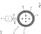
- Fig.2 shows a section through the centrifuge 2 from Fig.1 in the area of the sealing element 9, which is not shown in detail here.
- the view is directed at a rear wall 19 of the rotary insert 4, which is opposite the front opening 14 and which has a circular shape due to the hollow cylindrical surface 5 of the cylindrical rotary insert 4.
- the rear wall 19 of the rotary insert 4 has several through openings 20, through which there is permeability for the suspension S with the exception of the solid F contained therein.
- the through openings 20 of the rotary insert 4 from the centrifuge material chamber 6 with solvent L and/or polymer solution P.
- the through-openings 20 can also or alternatively be arranged in the outer surface 5 of the cylindrical rotary insert 4, where they form a kind of circumferential filter function.
- the gas-tight housing 3 enclosing the rotary insert 4 is designed around it in such a way that, during operation, the suspension S of polymer solution P (i.e. solvent L and plastic K dissolved therein) and solid F, which passes from the storage container 13 via the inlet 10 into the centrifuge material chamber 6, is centrifuged in a gas-tight manner within the housing 3.
- the rotary insert 4 is continuously flowed through via its through-openings 20 with solvent L and/or polymer solution P, while the solid F contained in the suspension S is retained.
- the primary reason for this is the simultaneous rotation of the rotary insert 4, which generates a centrifugal field within the centrifuge 2.
- the solid F is deposited in a manner not shown in detail on the outer surface 5 inside the rotary insert 4, while the lighter components of the suspension S (in the form of solvent S and/or polymer solution P) are clarified within the rotary insert 4.
- Solvent S and/or polymer solution P pass through the centrifugal field and are ultimately discharged via the second outlet 12, preferably continuously, into the second container 16.
- the solid F centrifuged out in this way is conveyed in a suitable manner, for example via a conveying device (eg screw) not shown in detail, against the direction of flow to the first outlet 11, via which it preferably continuously reaches the first container 15.
- the inerting device 17 serves to supply the inert gas T into the gas-tight system as required and in a targeted manner in order to at least partially displace a proportion of the oxygen contained therein, in particular within the housing (but also in the entire system). At the same time, this makes it possible to increase the internal pressure, in particular within the housing 3 (but also in the entire system), above atmospheric pressure. In this way, the suspension to be centrifuged and in particular the solvent L contained therein can be overheated to a temperature above its boiling point in order, for example, to increase or activate its reactivity with regard to the dissolving effect on the plastic K. By increasing the internal pressure to a value which is preferably above the vapor pressure of the solvent L, evaporation of the solvent is prevented.
- the manipulation of the internal pressure will be carried out via the inerting device 17 in combination with a compressor not shown here.
Landscapes
- Chemical & Material Sciences (AREA)
- Engineering & Computer Science (AREA)
- Life Sciences & Earth Sciences (AREA)
- Sustainable Development (AREA)
- Health & Medical Sciences (AREA)
- Chemical Kinetics & Catalysis (AREA)
- Medicinal Chemistry (AREA)
- Polymers & Plastics (AREA)
- Organic Chemistry (AREA)
- Environmental & Geological Engineering (AREA)
- Mechanical Engineering (AREA)
- Centrifugal Separators (AREA)
Claims (15)
- Centrifugeuse destinée à séparer au moins d'une matière solide (F) d'une suspension (S), en particulier d'une suspension de déchets, comprenant la matière solide (F) ainsi qu'une solution de polymère (P) avec au moins un solvant (L) et au moins une matière plastique (K) dissoute dans celle-ci, présentant un boîtier (3) avec un insert rotatif (4) logé de manière à pouvoir tourner dans ce boîtier, comprenant une réalisation du boîtier (3) entourant l'insert rotatif (4) de manière à ce que la suspension (S) puisse être centrifugée de manière étanche aux gaz à l'intérieur du boîtier (3), caractérisée par un dispositif d'inertisation (17) conçu et agencé pour augmenter une pression interne au moins à une valeur pour une pression de vapeur du solvant (L), et par un compresseur relié au boîtier (3) conçu pour manipuler une pression interne à l'intérieur du boîtier (3).
- Centrifugeuse selon la revendication 1, caractérisée en ce que le boîtier (3) possède une entrée (10) ainsi qu'au moins une sortie (11, 12), qui sont prévues pour introduire une suspension (S) ainsi que pour évacuer une solution de polymère (P) et/ou une matière solide (F) centrifugée.
- Centrifugeuse selon la revendication 1 ou 2, caractérisée en ce que l'insert rotatif (4) peut être traversé au moins temporairement par un solvant (L) et/ou une solution de polymère (P).
- Centrifugeuse selon l'une des revendications 1 à 3, caractérisée en ce que l'insert rotatif (4) présente une surface d'enveloppe (5), en particulier cylindrique creuse, équipée au moins par endroits d'ouvertures de passage (20), qui délimite une chambre de produit à centrifuger (6), les ouvertures de passage (20) de l'insert rotatif (4) pouvant être traversées par un solvant (L) et/ou une solution de polymère (P) depuis la chambre de produit à centrifuger (6).
- Centrifugeuse selon l'une des revendications 1 à 4, caractérisée en ce que le dispositif d'inertisation (17) est conçu et agencé pour déplacer au moins partiellement une fraction d'oxygène à l'intérieur du boîtier (3).
- Centrifugeuse selon l'une des revendications 2 à 5, caractérisée en ce que l'insert rotatif (4) est relié à l'entrée (10) ou à la sortie (11, 12) du boîtier (3) par une ouverture frontale (14).
- Centrifugeuse selon l'une des revendications 1 à 6, caractérisée en ce que l'insert rotatif (4) est couplé de manière à transmettre le couple à un arbre (7) pouvant être entraîné, l'arbre (7) traversant le boîtier (3) étant étanchéifié de manière étanche aux gaz par un dispositif d'étanchéité (9) au moins en un point (8); de préférence : le dispositif d'étanchéité (9) étant réalisé sous la forme d'une garniture mécanique, d'un joint d'arbre radial ou d'un presse-étoupe ou comprenant au moins l'un des modèles mentionnés.
- Centrifugeuse selon l'une des revendications 1 à 7, caractérisée par un récipient étanche aux gaz (15), relié au boîtier (3), dans lequel la matière solide (F) extraite par centrifugation de la suspension (S) peut être transférée en continu ; de préférence : le récipient étanche aux gaz (15) possédant une arrivée, la matière solide (F) transférée dans le récipient étanche aux gaz (15) pouvant être remise en suspension par l'ajout d'eau et/ou d'un solvant via l'arrivée.
- Centrifugeuse selon l'une des revendications 1 à 8, caractérisée par un sas étanche aux gaz à travers lequel la matière solide (F) centrifugée peut être retirée du boîtier (3) ou du récipient étanche aux gaz (15).
- Procédé de séparation d'au moins une matière solide (F) d'une suspension (S), telle qu'une suspension de déchets, au moyen d'une centrifugeuse (2), en particulier selon l'une des revendications 1 à 9, dans lequel la suspension (S) comprenant la matière solide (F) ainsi qu'une solution de polymère (P) avec au moins un solvant (L) et au moins une matière plastique (K) dissoute dans celle-ci est transférée dans une zone d'un insert rotatif (4) de la centrifugeuse (2), la suspension (S) étant centrifugée à l'intérieur d'un boîtier (3) de la centrifugeuse (2) entourant l'insert rotatif (4) de manière étanche aux gaz, caractérisé en ce qu'une pression interne est augmentée au moins à une valeur pour une pression de vapeur du solvant (L) et une pression interne à l'intérieur du boîtier (3) est manipulée par un compresseur.
- Procédé selon la revendication 10, caractérisé en ce que l'insert rotatif (4) est traversé au moins temporairement par un solvant (L) et/ou une solution de polymère (P).
- Procédé selon la revendication 10 ou 11, caractérisé en ce que l'insert rotatif (4) présente une surface d'enveloppe (5), en particulier cylindrique creuse, équipée au moins par endroits d'ouvertures de passage (20), qui délimite une chambre de produit à centrifuger (6), les ouvertures de passage (20) de l'insert rotatif (4) étant traversées par un solvant (L) et/ou une solution de polymère (P) depuis la chambre de produit à centrifuger (6).
- Procédé selon l'une des revendications 10 à 12, caractérisé en ce qu'une proportion d'oxygène à l'intérieur du boîtier (3) est au moins partiellement déplacée par l'introduction de gaz inerte (T).
- Procédé selon l'une des revendications 10 à 13, caractérisé en ce que la matière solide (F) extraite par centrifugation de la suspension (S) est transférée en continu dans un récipient étanche aux gaz (15) et relié au boîtier (3); de préférence: la matière solide (F) transférée dans le récipient (15) étant remise en suspension à l'intérieur de celui-ci par l'ajout d'eau et/ou d'un solvant via une arrivée du récipient (15).
- Utilisation d'une centrifugeuse (2) selon l'une des revendications 1 à 9 dans une installation de séparation de déchets (1), notamment pour un procédé de séparation d'au moins une matière solide (F) à partir d'une suspension (S) comprenant la matière solide (F) ainsi qu'une solution de polymère (P) avec au moins un solvant (L) et au moins une matière plastique (K) qui y est dissoute, telle qu'une suspension de déchets, selon l'une des revendications 10 à 14.
Applications Claiming Priority (2)
| Application Number | Priority Date | Filing Date | Title |
|---|---|---|---|
| DE102016015197.8A DE102016015197A1 (de) | 2016-12-21 | 2016-12-21 | Gasdichte Zentrifuge zur Feststoffabtrennung aus einer Polymerlösung sowie Verfahren zur Feststoffabtrennung aus einer Polymerlösung |
| PCT/EP2017/001439 WO2018114046A1 (fr) | 2016-12-21 | 2017-12-21 | Centrifugeuse étanche aux gaz pour séparer des solides d'une solution polymère et procédé pour séparer des solides d'une solution polymère |
Publications (3)
| Publication Number | Publication Date |
|---|---|
| EP3558542A1 EP3558542A1 (fr) | 2019-10-30 |
| EP3558542B1 true EP3558542B1 (fr) | 2024-06-19 |
| EP3558542C0 EP3558542C0 (fr) | 2024-06-19 |
Family
ID=60813565
Family Applications (1)
| Application Number | Title | Priority Date | Filing Date |
|---|---|---|---|
| EP17842416.4A Active EP3558542B1 (fr) | 2016-12-21 | 2017-12-21 | Centrifugeuse étanche aux gaz pour séparer des solides d'une solution polymère et procédé pour séparer des solides d'une solution polymère |
Country Status (3)
| Country | Link |
|---|---|
| EP (1) | EP3558542B1 (fr) |
| DE (1) | DE102016015197A1 (fr) |
| WO (1) | WO2018114046A1 (fr) |
Families Citing this family (5)
| Publication number | Priority date | Publication date | Assignee | Title |
|---|---|---|---|---|
| CN114058072A (zh) | 2020-08-07 | 2022-02-18 | Apk股份公司 | 通过集成的滚筒干燥和挤出从聚合物溶液除去溶剂的方法 |
| CN114055672A (zh) | 2020-08-07 | 2022-02-18 | Apk股份公司 | 通过塑料挤出机中集成的尺寸分级和挤出从聚合物溶液中除去溶剂的方法 |
| EP4192628A1 (fr) | 2020-08-07 | 2023-06-14 | Apk Ag | Procédé de prétraitement de matière plastique et de recyclage à base de solvant de matière plastique |
| CN114058073A (zh) | 2020-08-07 | 2022-02-18 | Apk股份公司 | 使用滚筒对滚筒加工步骤的基于溶剂的回收利用 |
| CN115501683B (zh) * | 2022-10-24 | 2024-07-26 | 济南新材料产业技术研究院 | 一种气体保护的负压溶剂过滤装置及方法 |
Family Cites Families (7)
| Publication number | Priority date | Publication date | Assignee | Title |
|---|---|---|---|---|
| DE3831023A1 (de) * | 1988-09-12 | 1990-03-15 | Herbold Gmbh Maschinenfabrik | Verfahren zum aufbereiten und wiederverwenden verschmutzter kunststoffprodukte |
| WO1993016808A1 (fr) * | 1992-02-24 | 1993-09-02 | Richter Gedeon Vegyészeti Gyár Rt. | Procede et appareil pour realiser des espaces clos a atmosphere inerte |
| EP0603434A1 (fr) | 1992-12-18 | 1994-06-29 | Karl Fischer Industrieanlagen Gmbh | Récupération de polyamide |
| DE4414750C2 (de) | 1993-04-29 | 1997-04-24 | Rolf Dipl Ing Schnause | Verfahren und Vorrichtung zum Reinigen viskoser Kunststoffschmelzen |
| DE19818183C2 (de) | 1998-04-23 | 2002-03-21 | Delphi Automotive Systems Gmbh | Vorrichtung und Verfahren zum Trennen der Bestandteile eines mindestens zwei Plastiksubstanzen unterschiedlicher Erweichungstemperatur enthaltenden Produktes |
| FR2877949B1 (fr) * | 2004-11-15 | 2007-11-23 | Solvay Sa Sa Belge | Procede d'epuration d'une solution de matiere plastique |
| JP5475919B1 (ja) * | 2013-11-01 | 2014-04-16 | 巴工業株式会社 | 密閉タイプのデカンタ型遠心分離機 |
-
2016
- 2016-12-21 DE DE102016015197.8A patent/DE102016015197A1/de not_active Withdrawn
-
2017
- 2017-12-21 EP EP17842416.4A patent/EP3558542B1/fr active Active
- 2017-12-21 WO PCT/EP2017/001439 patent/WO2018114046A1/fr not_active Ceased
Also Published As
| Publication number | Publication date |
|---|---|
| WO2018114046A8 (fr) | 2018-08-30 |
| DE102016015197A1 (de) | 2018-06-21 |
| WO2018114046A1 (fr) | 2018-06-28 |
| EP3558542C0 (fr) | 2024-06-19 |
| EP3558542A1 (fr) | 2019-10-30 |
Similar Documents
| Publication | Publication Date | Title |
|---|---|---|
| EP3558542B1 (fr) | Centrifugeuse étanche aux gaz pour séparer des solides d'une solution polymère et procédé pour séparer des solides d'une solution polymère | |
| EP3559100B1 (fr) | Solvant et procédé destiné à séparer par dissolution un plastique d'un solide à l'intérieur d'une suspension | |
| EP2419255B1 (fr) | Procede et dispositif de recyclage de matieres plastiques | |
| EP2101974B1 (fr) | Procédé de traitement initial, de retraitement ou de recyclage de thermoplastique | |
| EP2766163B1 (fr) | Dispositif pour préparer une matière plastique | |
| EP2525953B1 (fr) | Procédé et dispositif pour le traitement et la décontamination | |
| EP2917273B1 (fr) | Procédé et dispositif de traitement de polymères | |
| DE102008056311A1 (de) | Verfahren zum Abtrennen einzelner Wertstoffe aus gemischtem, insbesondere zerkleinertem Kunststoffabfall | |
| EP2823945B1 (fr) | Procédé et dispositif destinés à la récupération de déchets en plastique | |
| EP2052791A2 (fr) | Dispositif de nettoyage de produits en vrac | |
| DE69101296T2 (de) | Verfahren und Vorrichtung zur Behandlung von Abfällen. | |
| DE102016015199A1 (de) | Lösungsmittel sowie Verfahren zum Lösen wenigstens zweier Kunststoffe von einem Feststoff innerhalb einer Suspension | |
| DE69704161T2 (de) | Verfahren zur herstellung von kugelförmigen partikeln energetischer verbindungen | |
| EP4452598B1 (fr) | Ligne d'extrusion de film soufflé et procédé de production d'une bande de film | |
| EP0530228B1 (fr) | Procede et dispositif d'elimination d'emballages | |
| DE4414750C2 (de) | Verfahren und Vorrichtung zum Reinigen viskoser Kunststoffschmelzen | |
| EP2500164A1 (fr) | Installation et procédé de recyclage de matériaux synthétiques, de préférence PET | |
| AT508655B1 (de) | Verfahren zur aufbereitung und entgiftung | |
| EP0536650B1 (fr) | Procédé et dispositif pour sècher des substances humides | |
| DE4333876C2 (de) | Verfahren für Altteile bzw. Abfälle aus Kunststoff, insbesondere aus aufgeschäumtem Kunststoff | |
| WO2022200051A2 (fr) | Dispositif et procédé de traitement thermique de matières thermoplastiques fondues | |
| DE2832827A1 (de) | Verfahren zur entfernung von bitumen aus einer bitumenhaltigen wiederaufgeschlaemmten altpapiermasse | |
| DE102022124404A1 (de) | Verfahren zum Reinigen von Kunststoffabfall | |
| EP4499293A1 (fr) | Procédé et installation pour traiter des matériaux de déchets | |
| AT509389B1 (de) | Verfahren zur aufbereitung und entgiftung |
Legal Events
| Date | Code | Title | Description |
|---|---|---|---|
| STAA | Information on the status of an ep patent application or granted ep patent |
Free format text: STATUS: UNKNOWN |
|
| STAA | Information on the status of an ep patent application or granted ep patent |
Free format text: STATUS: THE INTERNATIONAL PUBLICATION HAS BEEN MADE |
|
| PUAI | Public reference made under article 153(3) epc to a published international application that has entered the european phase |
Free format text: ORIGINAL CODE: 0009012 |
|
| STAA | Information on the status of an ep patent application or granted ep patent |
Free format text: STATUS: REQUEST FOR EXAMINATION WAS MADE |
|
| 17P | Request for examination filed |
Effective date: 20190621 |
|
| AK | Designated contracting states |
Kind code of ref document: A1 Designated state(s): AL AT BE BG CH CY CZ DE DK EE ES FI FR GB GR HR HU IE IS IT LI LT LU LV MC MK MT NL NO PL PT RO RS SE SI SK SM TR |
|
| AX | Request for extension of the european patent |
Extension state: BA ME |
|
| DAV | Request for validation of the european patent (deleted) | ||
| DAX | Request for extension of the european patent (deleted) | ||
| REG | Reference to a national code |
Ref country code: HK Ref legal event code: DE Ref document number: 40014728 Country of ref document: HK |
|
| STAA | Information on the status of an ep patent application or granted ep patent |
Free format text: STATUS: EXAMINATION IS IN PROGRESS |
|
| 17Q | First examination report despatched |
Effective date: 20201118 |
|
| GRAP | Despatch of communication of intention to grant a patent |
Free format text: ORIGINAL CODE: EPIDOSNIGR1 |
|
| STAA | Information on the status of an ep patent application or granted ep patent |
Free format text: STATUS: GRANT OF PATENT IS INTENDED |
|
| INTG | Intention to grant announced |
Effective date: 20240130 |
|
| GRAS | Grant fee paid |
Free format text: ORIGINAL CODE: EPIDOSNIGR3 |
|
| GRAA | (expected) grant |
Free format text: ORIGINAL CODE: 0009210 |
|
| STAA | Information on the status of an ep patent application or granted ep patent |
Free format text: STATUS: THE PATENT HAS BEEN GRANTED |
|
| AK | Designated contracting states |
Kind code of ref document: B1 Designated state(s): AL AT BE BG CH CY CZ DE DK EE ES FI FR GB GR HR HU IE IS IT LI LT LU LV MC MK MT NL NO PL PT RO RS SE SI SK SM TR |
|
| REG | Reference to a national code |
Ref country code: GB Ref legal event code: FG4D Free format text: NOT ENGLISH |
|
| REG | Reference to a national code |
Ref country code: CH Ref legal event code: EP |
|
| REG | Reference to a national code |
Ref country code: DE Ref legal event code: R096 Ref document number: 502017016196 Country of ref document: DE |
|
| U01 | Request for unitary effect filed |
Effective date: 20240718 |
|
| U07 | Unitary effect registered |
Designated state(s): AT BE BG DE DK EE FI FR IT LT LU LV MT NL PT SE SI Effective date: 20240726 |
|
| PG25 | Lapsed in a contracting state [announced via postgrant information from national office to epo] |
Ref country code: HR Free format text: LAPSE BECAUSE OF FAILURE TO SUBMIT A TRANSLATION OF THE DESCRIPTION OR TO PAY THE FEE WITHIN THE PRESCRIBED TIME-LIMIT Effective date: 20240619 |
|
| PG25 | Lapsed in a contracting state [announced via postgrant information from national office to epo] |
Ref country code: GR Free format text: LAPSE BECAUSE OF FAILURE TO SUBMIT A TRANSLATION OF THE DESCRIPTION OR TO PAY THE FEE WITHIN THE PRESCRIBED TIME-LIMIT Effective date: 20240920 |
|
| U1O | Appointed representative for the unitary patent procedure deleted after the registration of the unitary effect | ||
| PG25 | Lapsed in a contracting state [announced via postgrant information from national office to epo] |
Ref country code: NO Free format text: LAPSE BECAUSE OF FAILURE TO SUBMIT A TRANSLATION OF THE DESCRIPTION OR TO PAY THE FEE WITHIN THE PRESCRIBED TIME-LIMIT Effective date: 20240919 Ref country code: HR Free format text: LAPSE BECAUSE OF FAILURE TO SUBMIT A TRANSLATION OF THE DESCRIPTION OR TO PAY THE FEE WITHIN THE PRESCRIBED TIME-LIMIT Effective date: 20240619 Ref country code: GR Free format text: LAPSE BECAUSE OF FAILURE TO SUBMIT A TRANSLATION OF THE DESCRIPTION OR TO PAY THE FEE WITHIN THE PRESCRIBED TIME-LIMIT Effective date: 20240920 Ref country code: RS Free format text: LAPSE BECAUSE OF FAILURE TO SUBMIT A TRANSLATION OF THE DESCRIPTION OR TO PAY THE FEE WITHIN THE PRESCRIBED TIME-LIMIT Effective date: 20240919 |
|
| U20 | Renewal fee for the european patent with unitary effect paid |
Year of fee payment: 8 Effective date: 20241119 |
|
| PG25 | Lapsed in a contracting state [announced via postgrant information from national office to epo] |
Ref country code: PL Free format text: LAPSE BECAUSE OF FAILURE TO SUBMIT A TRANSLATION OF THE DESCRIPTION OR TO PAY THE FEE WITHIN THE PRESCRIBED TIME-LIMIT Effective date: 20240619 |
|
| RAP2 | Party data changed (patent owner data changed or rights of a patent transferred) |
Owner name: LYB SOLVENT RECYCLING GMBH |
|
| U1K | Transfer of rights of the unitary patent after the registration of the unitary effect |
Owner name: LYB SOLVENT RECYCLING GMBH; DE |
|
| U1N | Appointed representative for the unitary patent procedure changed after the registration of the unitary effect |
Representative=s name: LYONDELLBASELL; DE |
|
| PG25 | Lapsed in a contracting state [announced via postgrant information from national office to epo] |
Ref country code: IS Free format text: LAPSE BECAUSE OF FAILURE TO SUBMIT A TRANSLATION OF THE DESCRIPTION OR TO PAY THE FEE WITHIN THE PRESCRIBED TIME-LIMIT Effective date: 20241019 |
|
| PG25 | Lapsed in a contracting state [announced via postgrant information from national office to epo] |
Ref country code: CZ Free format text: LAPSE BECAUSE OF FAILURE TO SUBMIT A TRANSLATION OF THE DESCRIPTION OR TO PAY THE FEE WITHIN THE PRESCRIBED TIME-LIMIT Effective date: 20240619 |
|
| PG25 | Lapsed in a contracting state [announced via postgrant information from national office to epo] |
Ref country code: RO Free format text: LAPSE BECAUSE OF FAILURE TO SUBMIT A TRANSLATION OF THE DESCRIPTION OR TO PAY THE FEE WITHIN THE PRESCRIBED TIME-LIMIT Effective date: 20240619 Ref country code: SK Free format text: LAPSE BECAUSE OF FAILURE TO SUBMIT A TRANSLATION OF THE DESCRIPTION OR TO PAY THE FEE WITHIN THE PRESCRIBED TIME-LIMIT Effective date: 20240619 |
|
| PG25 | Lapsed in a contracting state [announced via postgrant information from national office to epo] |
Ref country code: ES Free format text: LAPSE BECAUSE OF FAILURE TO SUBMIT A TRANSLATION OF THE DESCRIPTION OR TO PAY THE FEE WITHIN THE PRESCRIBED TIME-LIMIT Effective date: 20240619 Ref country code: SM Free format text: LAPSE BECAUSE OF FAILURE TO SUBMIT A TRANSLATION OF THE DESCRIPTION OR TO PAY THE FEE WITHIN THE PRESCRIBED TIME-LIMIT Effective date: 20240619 |
|
| PG25 | Lapsed in a contracting state [announced via postgrant information from national office to epo] |
Ref country code: SM Free format text: LAPSE BECAUSE OF FAILURE TO SUBMIT A TRANSLATION OF THE DESCRIPTION OR TO PAY THE FEE WITHIN THE PRESCRIBED TIME-LIMIT Effective date: 20240619 Ref country code: SK Free format text: LAPSE BECAUSE OF FAILURE TO SUBMIT A TRANSLATION OF THE DESCRIPTION OR TO PAY THE FEE WITHIN THE PRESCRIBED TIME-LIMIT Effective date: 20240619 Ref country code: RO Free format text: LAPSE BECAUSE OF FAILURE TO SUBMIT A TRANSLATION OF THE DESCRIPTION OR TO PAY THE FEE WITHIN THE PRESCRIBED TIME-LIMIT Effective date: 20240619 Ref country code: PL Free format text: LAPSE BECAUSE OF FAILURE TO SUBMIT A TRANSLATION OF THE DESCRIPTION OR TO PAY THE FEE WITHIN THE PRESCRIBED TIME-LIMIT Effective date: 20240619 Ref country code: IS Free format text: LAPSE BECAUSE OF FAILURE TO SUBMIT A TRANSLATION OF THE DESCRIPTION OR TO PAY THE FEE WITHIN THE PRESCRIBED TIME-LIMIT Effective date: 20241019 Ref country code: ES Free format text: LAPSE BECAUSE OF FAILURE TO SUBMIT A TRANSLATION OF THE DESCRIPTION OR TO PAY THE FEE WITHIN THE PRESCRIBED TIME-LIMIT Effective date: 20240619 Ref country code: CZ Free format text: LAPSE BECAUSE OF FAILURE TO SUBMIT A TRANSLATION OF THE DESCRIPTION OR TO PAY THE FEE WITHIN THE PRESCRIBED TIME-LIMIT Effective date: 20240619 |
|
| PLBE | No opposition filed within time limit |
Free format text: ORIGINAL CODE: 0009261 |
|
| STAA | Information on the status of an ep patent application or granted ep patent |
Free format text: STATUS: NO OPPOSITION FILED WITHIN TIME LIMIT |
|
| 26N | No opposition filed |
Effective date: 20250320 |
|
| PG25 | Lapsed in a contracting state [announced via postgrant information from national office to epo] |
Ref country code: MC Free format text: LAPSE BECAUSE OF FAILURE TO SUBMIT A TRANSLATION OF THE DESCRIPTION OR TO PAY THE FEE WITHIN THE PRESCRIBED TIME-LIMIT Effective date: 20240619 |
|
| REG | Reference to a national code |
Ref country code: CH Ref legal event code: PL |
|
| PG25 | Lapsed in a contracting state [announced via postgrant information from national office to epo] |
Ref country code: CH Free format text: LAPSE BECAUSE OF NON-PAYMENT OF DUE FEES Effective date: 20241231 |
|
| PG25 | Lapsed in a contracting state [announced via postgrant information from national office to epo] |
Ref country code: IE Free format text: LAPSE BECAUSE OF NON-PAYMENT OF DUE FEES Effective date: 20241221 |
|
| U20 | Renewal fee for the european patent with unitary effect paid |
Year of fee payment: 9 Effective date: 20251029 |
|
| PGFP | Annual fee paid to national office [announced via postgrant information from national office to epo] |
Ref country code: GB Payment date: 20251229 Year of fee payment: 9 |