EP3558602B1 - Panneau de commande de robot avec support supplémentaire pour un ordinateur tablette - Google Patents
Panneau de commande de robot avec support supplémentaire pour un ordinateur tablette Download PDFInfo
- Publication number
- EP3558602B1 EP3558602B1 EP17808322.6A EP17808322A EP3558602B1 EP 3558602 B1 EP3558602 B1 EP 3558602B1 EP 17808322 A EP17808322 A EP 17808322A EP 3558602 B1 EP3558602 B1 EP 3558602B1
- Authority
- EP
- European Patent Office
- Prior art keywords
- robot
- robot control
- tablet computer
- control panel
- handheld
- Prior art date
- Legal status (The legal status is an assumption and is not a legal conclusion. Google has not performed a legal analysis and makes no representation as to the accuracy of the status listed.)
- Active
Links
Images







Classifications
-
- B—PERFORMING OPERATIONS; TRANSPORTING
- B25—HAND TOOLS; PORTABLE POWER-DRIVEN TOOLS; MANIPULATORS
- B25J—MANIPULATORS; CHAMBERS PROVIDED WITH MANIPULATION DEVICES
- B25J13/00—Controls for manipulators
- B25J13/06—Control stands, e.g. consoles, switchboards
- B25J13/065—Control stands, e.g. consoles, switchboards comprising joy-sticks
-
- B—PERFORMING OPERATIONS; TRANSPORTING
- B25—HAND TOOLS; PORTABLE POWER-DRIVEN TOOLS; MANIPULATORS
- B25J—MANIPULATORS; CHAMBERS PROVIDED WITH MANIPULATION DEVICES
- B25J13/00—Controls for manipulators
- B25J13/02—Hand grip control means
Definitions
- the invention relates to a robot control panel, having a first holder, which is designed for the form-fitting receiving of a separately portable handheld robot operating device that can be removed from the robot control panel.
- the DE 10 2010 025 781 A1 describes a portable safety input device with at least one input means for inputting a safety signal to a robot controller, which has an interface for communication with a hand-held device, particularly detachably connected to the safety input device, for controlling a robot by means of communication with this robot controller.
- the WO 2013/029 658 A1 describes an industrial robot with a robot controller to which an enabling device is connected via a first signal line for signal transmission.
- a hand-held operating device which is embodied separately from the approval device is connected to the approval device for signal transmission via a second signal line.
- the consent device can have a physical connection point to which the hand-held control device can be mechanically fastened in a manually detachable manner so that in an assembled state the consent device forms a structural unit with the hand-held control device.
- the DE 10 2015 206 578 B3 shows a robot control hand-held device with a housing and a handle, the control hand-held device being insertable in a receptacle on a robot.
- the housing also has a receptacle for an electronically communicating device.
- the object of the invention is to improve the manual control and the programming of a robot by means of a handheld robot operating device, in particular to make it more ergonomic.
- a form-fitting receiving can in particular be an insertion in which the robot handheld device or the tablet computer is inserted into a corresponding receptacle, such as a pocket, a channel, a slot or a fork, so that the holder holds the handheld robot handheld device or surrounds the tablet computer from the outside, in particular on opposite sides of the handheld robot operating device or the tablet computer.
- a form-fitting recording can, however, also be achieved by simply attaching the handheld robot operating device or the tablet computer to the respective holder, for example by attaching a tab of the handheld robot operating device to a hook of the holder.
- a form-fitting pick-up can optionally also be supported by a magnet, through which the robot control hand-held device or the tablet computer in addition to a form-fitting Recording is additionally secured by means of magnetic force.
- the communication device is set up, in particular, to connect the handheld device controller of a handheld robot operating device and / or the tablet computer controller of the tablet computer to a robot controller in terms of control technology, which is inserted into the robot control desk.
- the communication device can, however, generally be set up to coordinate, in particular set up, create, terminate and / or prevent or not the assignment of one or more robot handheld devices and / or one or more tablet computers to one or more robot controls to allow.
- both the respective robot handheld device, the respective tablet computer, the respective robot controller and the respective robot control desk can communicate with each other in a wired / contact-based and / or wireless / radio-connected manner, ie exchange signals, data and / or information.
- the communication device of the robot control desk can serve as a central coordination device.
- the robot control desk can be designed or the communication device can be set up to be permanently, ie uniquely connected to an individual robot controller and a communication connection between this robot controller and a specific handheld robot control device and / or a specific tablet computer is then automatically set up and / or approved as soon as this robot handheld device or this Tablet computer is inserted into the respective holder of the robot control panel.
- the robot handheld device connected to the assigned robot controller or the tablet computer connected to the assigned robot controller is removed from the respective holder of the robot control desk, it can either be provided that the established and / or approved communication connection is disconnected, or it can be provided be that the established and / or approved communication connection continues to exist. Then the assigned robot control can continue to be controlled by that robot handheld device or that tablet computer in a state of the robot handheld device or the tablet computer that is handled by a person, even if the handheld robot handheld device or the tablet computer from the Is removed from the robot control panel.
- a robot control hand-held device and / or a tablet computer is then connected in any case to an assigned robot control alone in terms of control technology, which robot control is coupled or is control-technically connected to that robot control desk, on which robot control desk the relevant robot control device and / or the tablet computer in question is inserted in the respective holder.
- the associated robot i. E. the assigned robot controller can be controlled and / or programmed by the handheld robot operating device used in the robot control panel and / or by the tablet computer inserted into the manual robot control panel.
- a tablet computer can be inserted into the robot control panel independently of the robot control pendant and / or independently of the robot control pendant because a second holder, which is different from the first holder and is designed to positively receive a separately portable tablet computer that can be removed from the robot control console can be taken from the robot control panel.
- a robot can be controlled either individually via the handheld robot control unit or individually via the tablet computer.
- the robot can continue to be controlled by the tablet computer or the removed robot operating hand-held device, with a user having at least one hand or even both hands free since the tablet computer and / or the robot handheld device is held by the robot control panel.
- the robot control panel can have a sensor which is designed to identify an individual robot operating handset and / or tablet computer inserted into the robot control panel, and the communication device is designed to control the operating handset control of the robot operating handset and / or the tablet computer Depending on the individual robot operating hand-held device and / or tablet computer identified by the sensor, to be connected in terms of control technology to a robot controller assigned to the individual robot operating hand-held device and / or the individual tablet computer.
- the robot control panel has a sensor which is designed to identify an individual robot operating handset inserted into the robot control panel, and the communication device is designed to control the used robot operating handset as a function of the individual robot operating handset identified by the sensor with one of the individual
- a specific, ie individual robot control handset of several robot control handsets can optionally, ie depending on the needs of the respective robot operator, be connected in a clear and / or technically safe manner with a specific, ie individual robot control , ie assigned, so that it is unambiguously ensured which individual robot handheld device with which individual Robot or its robot controller is connected.
- a specific handheld robot control device and then another handheld robot control device can optionally be connected to the robot control of the same robot without conflicts.
- An assignment of a specific, individual robot hand-held device to a specific, individual robot control and thus to the robot can take place automatically by inserting the robot hand-held device into the robot control panel.
- An assignment of the robot hand-held device to the robot control made by the initial insertion can also be maintained in a first case when the inserted robot hand-held device is removed from the robot control panel again.
- the assignment of the robot handheld device to the robot controller can be automatically canceled, i.e. can be terminated as soon as the robot handheld unit is removed from the robot control panel.
- the robot control assigned to the robot control panel can be automatically connected to this new robot hand-held device inserted in the robot control panel and the previous assignment of the robot control to the previous robot hand-held device can be canceled, i.e. be separated.
- What is described for the individual robot operating hand device applies, alternatively or in addition, in an analogous manner to the respective individual tablet computer.
- the communication device can be controlled by means of a communication connection with a robot controller be connected, the communication device can have at least one first sensor which is designed to identify a robot operating hand-held device received on the robot control desk and have at least one second sensor which is designed to identify a tablet computer received on the robot control desk, wherein the communication device is also designed to register the robot control hand-held device identified by the first sensor and the tablet computer identified by the second sensor with the robot controller as a first hand control device and a second hand control device for controlling a robot arm controlled by the robot control.
- Each handheld robot operating device and each tablet computer can have an identification that individualizes the particular handheld robot operating device and the particular tablet computer.
- An identification can be, for example, an optical identification, for example by means of an optical bar code or a QR code.
- a label can also be digitally stored information, for example by means of contactless transmitter-receiver systems, such as near-field sensors (NFC or RFID transponders) or wired via a data connection between the robot handheld device, the tablet computer and can be transferred to the robot control panel.
- the robot handheld device is registered with the robot controller as a handheld control device for controlling a robot arm controlled by the robot controller, then communication between the handheld device controller and the robot controller is possible, in particular using safe technology possible. There is then a clear connection between the robot handheld device and the assigned robot.
- the tablet computer is registered with the robot controller as a manual control device for controlling a robot arm controlled by the robot controller, communication between the tablet computer controller and the robot controller is possible, in particular using safe technology. There is then a clear connection between the tablet computer and the assigned robot.
- the communication device can be configured to include at least one input means, arranged on the robot handheld device, from the group of input devices of the handheld robot handheld device, comprising an emergency stop button, an operating mode selector switch, an approval button and a 3D / 6D mouse, for transmitting an input signal to the robot controller to enable due to a manual input on the corresponding input means of the robot handheld device when the robot handheld device is used in the first holder of the robot control desk and also to allow safety-related inputs via the tablet computer for transmission to the robot controller when the tablet computer is in is inserted into the second bracket of the robot control panel.
- the at least one input means for transmitting an input signal to the robot controller due to a manual input on the corresponding input means of the robot hand-held device remain functional, although the robot hand-held device is removed from the robot control panel. This can be allowed because the handheld robot operating device carries the basic safety-relevant input means with it.
- the communication device can be configured to include at least one input means, arranged on the robot handheld device, from the group of input devices of the handheld robot handheld device, comprising an emergency stop button, an operating mode selector switch, an approval button and a 3D / 6D mouse, for transmitting an input signal to the robot controller based on a manual entry at the corresponding To enable input means of the robot handheld device when the robot handheld device is inserted in the first holder of the robot control panel and to prevent safety-related inputs via the tablet computer for transmission to the robot controller when the tablet computer is removed from the second holder of the robot control panel.
- enabling input means by the communication device is understood to mean that, in the case of existing mechanical input devices (hardware input means), these input means are set up to be functional, so that these mechanical input means can be used manually and corresponding functions are thereby triggered in the robot controller can be.
- the mechanical input devices are still physically present, but cannot trigger any function on the robot controller, since in this case they are not set up for this, ie they are integrated in the control technology.
- the communication device can, on the one hand, enable input means be understood that by enabling the software input means are only displayed on the touch screen, and can only be seen by a user if they are also functional, ie corresponding functions by touching the graphic objects of these "soft keys” in the robot controller can be triggered and otherwise, ie when the software input means are not activated, the graphic objects of the "soft keys” are hidden.
- activating input means can also be understood by the communication device that by enabling the software input means on the touch screen are displayed particularly clearly, sharply, in color and / or illuminated and only then are functional, ie corresponding functions by touching the graphic objects of this "soft- Keys "can be triggered in the robot controller and otherwise, ie if the software input means are not activated, the graphic objects of the" soft keys "are indistinct, blurred, in black / white or gray, and / or unlit and then not functional are, ie no corresponding functions can be triggered by touching the graphic objects of these "soft keys” in the robot controller.
- the activation of the input means is ended, ie the at least one input means for transmitting an input signal to the robot control is due manual input on the corresponding input means of the tablet computer does not remain functional, but is deactivated by the communication device, ie the activation is terminated when the tablet computer is removed from the robot control panel.
- the tablet computer generally does not have any basic safety-relevant input means, such as an emergency stop button, with it.
- a mere display of information on the tablet computer can, however, still be permitted by the communication device.
- the communication device can be designed to display information transmitted from the robot controller on a display device of the tablet computer when the tablet computer is registered with the robot controller and has been removed from the second holder of the robot control panel.
- Safety-relevant inputs include, for example, safety-relevant input means, in particular an emergency stop button, an operating mode selector switch and / or an approval button.
- the safety-related functions can, however, continue to take place via the tablet computer if the tablet computer is still attached to the second holder of the robot control panel and the robot control panel itself is via the necessary safety-related input means, in particular an emergency stop button, an operating mode selector switch and / or an approval button , has. In this case, the safety-relevant functions even continue to take place via the tablet computer when the robot handheld device has been removed from the robot control panel.
- the tablet computer can display all possible types of information on a display of the tablet computer.
- Settings relating to the configuration of the robot controller and / or the robot can also be confirmed, changed, overwritten and / or deleted by means of the tablet computer if the settings are not safety-relevant for the operation of the robot.
- the tablet -Computer has its own safety-related input means, in particular an emergency stop button, an operating mode selector switch and / or an approval button, or it is necessary that the robot handheld device is inserted into the robot control panel, at least then the robot handheld device via the safety-relevant input device , in particular an emergency stop button, an operating mode selector switch and / or an enabling button has.
- the robot control desk can also have the safety-relevant input means, in particular an emergency stop button, an operating mode selector switch and / or an approval button. Then it would be harmless if the robot handheld device were removed from the robot control panel.
- the communication device can be set up to continue to display information on a display means of the tablet computer when the tablet computer is removed, but safety-related inputs via the tablet computer for transmission to the robot controller are prevented, i.e. cannot be made effective.
- the robot control console can have a housing on which at least one input device from the group of input devices is installed, comprising an emergency stop button, an operating mode selector switch, an approval button and a 3D / 6D mouse for transmitting an input signal to the robot controller based on a manual input on the corresponding input means of the robot control panel, and the communication device can be designed to allow safety-related inputs via the tablet computer for transmission to the robot controller when the tablet computer is inserted in the second holder of the robot control panel and the at least one input means of the robot control panel for Transmission of an input signal to the robot controller is enabled on the basis of a manual input on the corresponding input means of the robot control desk.
- the communication device can be designed to allow safety-related inputs via the tablet computer for transmission to the robot controller when the tablet computer is inserted in the second holder of the robot control panel and the at least one input means of the robot control panel for Transmission of an input signal to the robot controller is enabled on the basis of a manual input on the corresponding input means of the robot control desk.
- the robot handheld device can be removed from the robot control desk.
- the basic safety-relevant input means such as, for example, the emergency stop button, of the robot operating hand-held device are removed from the robot control panel. So if the robot control desk does not have any safety-related input means, the safety-related inputs would have to be transferred to the tablet computer robot control can be prevented even if the tablet computer remains in the robot control desk. However, if the robot control desk itself has safety-relevant input means, then a safety-relevant input via the tablet computer can be permitted by the communication device.
- the robot control desk can have a wireless communication interface which is designed to connect a control handset control of the robot control handset to the robot control when the robot control handset is removed from the first holder of the robot control desk.
- the robot control panel can have a wireless communication interface which is designed to connect the tablet computer controller of the tablet computer to the robot controller in terms of control technology when the tablet computer is removed from the second holder of the robot control panel.
- the wireless communication interface can ensure that the established and / or approved communication connection continues to exist .
- the assigned robot controller can then continue to be controlled by that robot operating hand-held device or that tablet computer in a state of the robot operating hand-held device or the tablet computer that is being handled by a person even if the robot handheld device or tablet computer has been removed from the robot control panel.
- the second holder can have a clamping device which is designed to grip around two opposite edge sections of the tablet computer when the tablet computer is inserted in the second holder.
- the tablet computer can easily be mechanically connected to the robot control panel manually, in particular without the need for special tools, and also mechanically detached from the robot control panel, in particular detached without being destroyed.
- the clamping device can in particular be designed to hold the tablet computer in a force-fitting and / or form-fitting manner.
- the clamping device can have a first clamping element attached to a housing of the robot control panel and a second clamping element mounted on the robot control panel so that it can be adjusted between a storage position and an extended position, the first clamping element and the second clamping element being formed, the tablet computer in the extended position of the second To grip clamping elements at two opposite edge sections.
- the adjustably mounted second clamping element can have several discrete pull-out positions or be continuously extendable so that a multitude of tablet computers of different sizes can be mechanically coupled to the robot control desk.
- the robot control console can have a spring device which is designed to mount the second clamping element in its storage position in a prestressed manner.
- the second clamping element Since the second clamping element is pretensioned in its storage position by means of a spring device, the second clamping element moves automatically into the storage position as soon as the tablet computer is removed from the robot control panel.
- the spring device exerts a clamping force on the tablet computer when the tablet computer is inserted into the second holder of the robot control panel, as a result of which the tablet computer is mechanically held particularly securely on the robot control panel.
- the robot control console can have a cover cap releasably attached to the housing of the robot control console, which cover cap is designed to be flush with the housing of the robot control console in its state attached to the housing and to visually cover the clamping device when the tablet computer is removed from the robot control console.
- the cover cap can not only cover the first clamping element attached to the housing of the robot control panel, but also cover the second clamping element in its storage position as soon as the tablet computer is removed from the robot control panel.
- the invention describes, possibly independently of what has been described so far, sometimes expressed differently than previously, thus an innovative, intelligent robot control desk.
- This robot control desk can have a wide variety of functions in order to be able to couple, recognize and / or load the robot operating handset in such a way that this robot operating handset the user can continue to use the full or modified range of functions even in a state connected to the robot control panel.
- the robot control panel is designed in such a way that it has two independent mechanical coupling devices, namely a first coupling device that is designed to mechanically couple the robot control handset directly to the robot control panel and a second coupling device that is designed
- the tablet -Coupling the computer mechanically as an independent device directly to the robot control desk offers a high degree of flexibility and, at the same time, less Complexity of the device.
- the only disadvantage to be mentioned is that the robot handheld device and the tablet computer must always be inserted separately and individually into the robot control panel. However, this can be done quickly and easily.
- the robot control panel has a first receptacle for the robot handheld device and a second receptacle or holder with the option of mechanically coupling the tablet computer separately, so that the user has a powerful combination control device when the handheld robot handset and tablet computer are inserted is available, which is firmly positioned in the room.
- this combination device can then have a large touch display and is thus at least comparable to a functionally very extensive and powerful classic operating terminal.
- the advantages of the divisible hand-held control device including a tablet computer also apply to the convertible control terminal.
- the user takes his, in particular, personalized tablet computer with him to the robot or to the robot cell, after the mechanical coupling process he has a user interface that is optimally tailored to him and is already known according to his desired tasks and roles.
- the tablet computer can also be used for many other interactions with the robot, for example for commissioning, for maintenance, for service, for assistance and / or for optimizing the robot.
- the tablet computer offers a multitude of supporting functions through its existing sensors, such as a camera, acceleration sensors, telephoning, navigation sensors (GPS), compass, video telephony, augmented reality, etc., so that these functions can also be made available for robot applications.
- sensors such as a camera, acceleration sensors, telephoning, navigation sensors (GPS), compass, video telephony, augmented reality, etc.
- the robot control panel has two independent mechanical coupling devices (robot operating handset on the robot control panel and tablet computer on the robot control panel) makes it particularly helpful when the user wants to have both hands free. Having both hands free can be useful, for example, to be able to use a robot set up for human-robot collaboration (HRC), in particular a lightweight robot, to make calls, or to use the hardware of the robot application or the robot itself Modify by hand.
- HRC human-robot collaboration
- the tablet computer can be fastened to the robot control desk, for example, by means of a clamping connection which, for example, can have two opposite clamping jaws.
- the tablet computer can be connected to two opposite side edges are gripped, ie clamped.
- This can do Robot control desk for example, have a retaining edge fixed to the frame with a groove and a vertically movable and spring-loaded counterholder, in particular spring-loaded via constant force springs such as scroll springs.
- Such a mechanism can also be concealed by a horizontally movable and spring-loaded panel so that it is unobtrusively integrated into the overall design.
- Additional design elements provided on the robot control panel can intuitively indicate the respective function and use.
- the tablet computer for example, it can simply be pressed against an easily displaceable panel of the robot control desk and placed with the lower edge on a counter-holder that is then released and located in the upper position. This counter holder is then guided vertically downwards with the tablet computer so that the tablet computer can securely snap into place behind the retaining edge.
- a button integrated in the robot control panel can be used to recognize that a tablet computer is being inserted.
- a control-technical coupling of the tablet computer with the robot control then ensures, for example, the link to the correct control.
- a control-related coupling can also take place visually, for example via a QR code, or tactilely, for example via a multi-touch display of the tablet computer.
- a user-friendly and confusion-free allocation of tablet computer and robot controller On the one hand, and the assignment of the robot handheld device and the robot controller, on the other hand, can also be done by naming the corresponding robot on the tablet computer and / or supported by a flashing signal light on the robot or in the vicinity of the robot. The recognition of the correct robot can or must be consciously confirmed by the user, for example by an input on the tablet computer.
- the tablet computer can also be registered with the robot controller, for example, by holding the tablet computer only in front of the bracket of the robot control panel or against the concealed bracket of the robot control panel, but without inserting the tablet computer into the bracket of the robot control panel.
- the tablet computer and the robot controller can also be linked in terms of control technology, but only in a display mode, for example, that is to say that no safety-relevant parameters may be changed, commands started or manual movements of the robot carried out. This is particularly necessary because it must be ensured that an emergency stop button is in the vicinity.
- some safety-relevant functions can definitely be activated on the tablet computer, ie made functional.
- the robot handheld device is also mechanically coupled in the robot control panel, all functions are available to the user via the consent buttons and the local emergency stop button on the handheld robot handheld device that are also possible when the tablet computer is directly coupled to the handheld robot handheld device .
- the tablet computer and the robot handheld device are connected to one another via the robot control panel.
- the tablet computer can be charged either wirelessly, for example via induction or via a cable.
- the robot control panel presented provides the user with four additional operating options using just one additional device.
- the robot control desk can be linked to the robot controller in terms of control technology and the user holds the robot control pendant alone in his hand or the user holds the robot control pendant in his hand, the tablet computer being attached to the handheld robot control pendant.
- the robot control panel can be linked to the robot controller in terms of control technology and the robot operating hand-held device can be inserted into the robot control panel.
- the user then only holds the tablet computer alone in his hands or has nothing in his hands, but can access the robot control via the robot handheld device mounted on the robot control panel by making manual entries on the stationary robot handheld device.
- the robot control desk can be linked to the robot controller in terms of control technology and the tablet computer can be attached to the robot control desk.
- the user then only holds the handheld robot operating device, which is equipped without a tablet computer, in his hand and the user can access the tablet computer mounted on the robot control panel in order to make control inputs.
- the robot control panel can be linked to the robot controller in terms of control technology, and both the robot operating hand device and the tablet computer are attached to the robot control panel. The user then does not hold anything in his hand, but can access the robot handheld device that is stationary in the robot control panel and the tablet computer that is stationary at the robot control panel.
- the present invention discloses a convertible control terminal which is based on the use of a robot control panel and enables new usage scenarios through coupling options of the robot control hand-held device and tablet computer, which offers the user great freedom of operation.
- the user interface created in this way can quickly and easily change from a large and powerful terminal to a small mobile input device by removing the required components.
- Such a convertible robot control panel rounds off the universal use of a divisible robot control handset with the inclusion of a tablet computer and creates a large field of new control options for the robot.
- the FIGS. 1 to 8 show an exemplary robot control desk 1.
- the robot control desk 1 has a first holder 2.1, which is designed to hold a separately portable handheld robot operating device 3 that can be removed from the robot control desk 1 in a form-fitting manner.
- the robot control panel 1 also has an electrical charging device 4, which is designed to charge a rechargeable electrical energy store 5 of the robot handheld device 3 in a state of the robot handheld device 3 recorded on the robot control panel 1, and a communication device 6, which is designed, a handheld device controller 7 of the handheld robot operating device 3 with a robot controller 8 ( FIGS. 9 to 12 ) to be connected in terms of control technology.
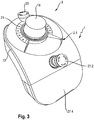
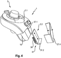
- the first holder 2.1 has a latching means 9 which is designed to interact with at least one counter-latching means 10, which corresponds to the latching means 9, of the robot control hand-held device 3 in a state of the robot control hand-held device 3 recorded on the robot control panel 1, such as that the robot control hand-held device 3, in its state recorded on the robot control panel 1, assumes a fixed, predetermined, unambiguous orientation relative to the robot control panel 1, as shown in particular in FIG Fig. 3 and Fig. 4 is shown.
- the first holder 2.1 also has a pocket 11, the inner surface of which has a shape corresponding to a grip section 12 of the robot hand-held device 3, such that when the robot hand-held device 3 is in a state of the robot hand-held device 3, its handle portion 12 is received in a form-fitting manner in the pocket 11 of the robot control desk 1.
- the first holder 2.1 also has a radially open ring receptacle 13 such that the ring receptacle 13 has a housing section 14 of the robot hand-held device 3 when the robot hand-held device is in a state of the robot hand-held device on the robot control panel 1 3 encompasses positively, as shown in particular in FIGS.
- the ring receptacle 13 has a housing section 14 of the robot handheld device 3 over a partial circumference encompassing first leg section 13.1 and has a second leg section 13.2 opposite the first leg section 13.1, which surrounds the housing section 14 of the robot handheld device 3 over another partial circumference, and a first free end 15.1 of the first leg section 13.1 is arranged at a distance from a second free end 15.2 of the second leg section 13.2, as for example in FIG Fig. 1 so that a penetration gap S is formed between the two free ends 15.1 and 15.2 ( Fig.1 and Fig. 2 ), via which the robot handheld device 3 can be grasped from behind with one hand in spite of its state recorded on the robot control panel 1 in order to be able to manually detect a rear side of the housing section 14 of the handheld robot handheld device 3.
- the handheld robot operating device 3 has an essentially circular-cylindrical housing 18.
- the grip section 12 extends vertically downward on its bottom side.
- a 3D / 6D mouse 19, an emergency stop button 20 and / or an operating mode selector switch 21 can be arranged on an upper side of the circular cylindrical main housing 18.
- the open ring receptacle 13 of the first holder 2.1 of the robot control panel 1 can be designed to encompass the circular-cylindrical housing 18 of the robot control hand-held device 3 when the robot control hand-held device 3 is inserted into the robot control console 1.
- the first leg section 13.1 of the ring receptacle 13 encloses the circular cylindrical housing 18 of the robot handheld device 3 on the right and the second leg portion 13.2 of the ring receptacle 13 encompasses the circular cylindrical housing 18 of the robot handheld device 3 on the left, with the first free end 15.1 of the first leg section 13.1 is arranged at a distance S from the second free end 15.2 of the second leg section 13.2. Accordingly, a radial opening of the ring receptacle 13 is formed between the first free end 15.1 of the first leg section 13.1 and the second free end 15.2 of the second leg section 13.2.
- the radial opening of the ring receptacle 13 allows a user to encompass the circular cylindrical housing 18 of the robot handheld device 3 up to a rear side 17 with his hand without the first holder 2.1 or the ring receptacle 13 grasping the robot handheld device 3 in it Area would prevent.
- an enabling button arranged on the rear of the circular cylindrical main housing 18 of the robot handheld device 3 can be manually accessed even if the handheld robot handheld device 3 is inserted in the robot control desk 1. Irrespective of this, it is generally easier to remove the handheld robot operating device 3 from the robot control desk 1 by hand.
- the robot control desk 1 has a first holder 2.1, which is designed to hold a separately portable handheld robot operating device 3 that can be removed from the robot control desk 1 in a form-fitting manner.
- the robot control panel 1 has a second holder 2.2, which is different from the first holder 2.1 and which is used separately for the form-fitting receiving of one that can be removed from the robot control panel 1 portable tablet computers 36 ( Fig. 5 ) is trained.
- the robot control console 1 has the communication device 6, which is designed to connect a handheld control unit 7 of the handheld robot control unit 3 and a tablet computer control 36.1 of the tablet computer 36 to the robot controller 8 in terms of control technology.
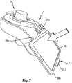
- a clamping device 37 which is designed to grip around two opposite edge sections 36a and 36b of the tablet computer 36 when the tablet computer 36 is inserted in the second holder 2.2., as shown in FIG Fig. 7 is shown.
- the clamping device 37 has a first clamping element 37.1 fastened to the housing 18 of the robot control desk 1 and a first clamping element 37.1 on the robot control desk 1 between a storage position ( Fig. 5 ) and a pull-out position ( Fig. 6 , Fig. 7 ) adjustably mounted second clamping element 37.2, the first clamping element 37.1 and the second clamping element 37.2 being designed to encompass the tablet computer 36 in the extended position of the second clamping element 37.2 at two opposite edge sections 36a and 36b, as shown in Fig. 7 is shown.
- the second clamping element 37.2 By means of a spring device 38, the second clamping element 37.2 can be moved into its storage position according to FIG Fig. 5 be stored prestressed. If the tablet computer 36, as in Fig. 6 shown, with its lower edge portion 36b attached to the stored second clamping element 37.2, the second clamping element 37.2 can be pulled out against the spring force of the spring device 38 downwards until the upper edge section 36a of the tablet computer 36 can be inserted under the fixed first clamping element 37.1, as shown in FIG Fig. 7 is shown. If the tablet computer 36 is now released, the second clamping element 37.2 holds the tablet computer 36 on the robot control desk 1 due to the spring preload.
- the robot control desk 1 can also have an aperture cap 27.4 detachably attached to the housing of the robot control desk 1 ( Fig. 4 ), which is designed to be flush with the housing 18 of the robot control panel 1 in its attached state to the housing 18 and to visually cover the clamping device 37 when the tablet computer 36 is removed from the robot control panel 1, as shown in FIG FIGS. 1 to 3 is shown.
- the robot control panel has a wireless communication interface 39 which is designed to connect the handheld control unit 7 of the handheld robot control unit 3 to the robot control 8 ( FIGS. 9 to 12 ) when the robot handheld device 3 has been removed from the first holder 2.1 of the robot control panel 1.
- the robot control desk also has a wireless communication interface 39 which is designed to connect the tablet computer controller 36.1 of the tablet computer 36 to the robot controller 8 ( FIGS. 9 to 12 ) when the tablet computer 36, as in Fig. 8 shown, is taken from the second holder 2.2 of the robot control panel 1.
- the communication device 6 can by means of a communication connection 23 (esp. Fig. 9 ) be connected in terms of control technology to a robot controller 8, the communication device 6, as in FIG Fig. 2 shown, has at least one first sensor 24.1, which is designed to identify a robot control hand-held device 3 received on the robot control desk 1 and has at least one second sensor 24.2, as in FIG Fig. 5 which is designed to identify the tablet computer 36 accommodated on the robot control desk 1, the communication device 6 also being designed to include the robot handheld device 3 identified by the first sensor 24.1 and the tablet computer 36 identified by the second sensor 24.2 to register with the robot controller 8 as a first manual control device and a second manual control device for controlling a robot arm 25 controlled by the robot controller 8.
- a communication connection 23 esp. Fig. 9
- the communication device 6 as in FIG Fig. 2 shown, has at least one first sensor 24.1, which is designed to identify a robot control hand-held device 3 received on the robot control desk 1 and has at least one second sensor 24.2, as in
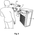
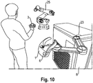
- the Fig. 9 shows a first robot operating scenario in which the robot control desk 1 is provided with the inserted robot operating hand-held device 3 and only the tablet computer 36 has been removed.
- the communication device 6 is designed to have at least one input means arranged on the robot hand-held device 3 from the group of input devices of the hand-held robot control device 3, including, for example, the emergency stop button 20, the operating mode selector switch 21 and the 3D / 6D mouse 19, for transmitting a To enable input signal to the robot controller 8 due to a manual input on the corresponding input means of the robot handheld device 3 when the robot handheld device 3 is inserted in the first holder 2.1 of the robot control desk 1.
- the input means not yet for transmitting an input signal to the robot controller 8 due to a manual input at the corresponding input means of the robot handheld device 3 are enabled by the communication device 6. Only when the robot handheld device 3 is inserted into the first holder 2.1 of the robot control desk 1 for the first time, as in FIG Fig. 9 As shown, the handheld robot operating device 3 is enabled in such a way that the at least one input means for transmitting an input signal to the robot controller 8 is functional on the basis of a manual input on the corresponding input means of the handheld robot operating device 3.
- the activation of the input means can be retained, ie the at least one input means for transmitting an input signal to the robot controller 8 due to a manual input on the corresponding input means of the robot handheld device 3 remains functional, although the robot handheld device 3 from the robot control desk 1 is removed.
- the robot handheld device 3 carries the basic safety-relevant input means, for example the emergency stop button 20, the operating mode selector switch 21 and the 3D / 6D mouse 19.
- the communication device 6 only allows information transmitted from the robot controller 8 to be displayed on a display means 40 of the tablet computer 36. Safety-relevant inputs via the tablet computer 36 for transmission to the robot controller 8 are prevented when the tablet computer 36 is removed from the second holder 2.2 of the robot control desk 1.
- the robot control desk 1 is provided with an inserted tablet computer 36 and only the robot control hand-held device 3 is removed for manual handling by a person.
- the robot control panel 1 has a housing on which at least one further emergency stop button 27.2 is arranged for transmitting an input signal to the robot controller 8 based on a manual input to the corresponding emergency stop button 27.2 of the robot control panel 1, so that the communication device 6 in this case allows security-related inputs to be made via the tablet computer 36 for transmission to the robot controller 8, since the tablet computer 36 is also inserted in the second holder 2.2 of the robot control desk 1.
- the at least one input means of the robot control panel 1, ie in this case the further emergency stop button 27.2 is enabled to transmit an input signal to the robot controller 8 on the basis of a manual input at the corresponding emergency stop button 27.2 of the robot control panel 1.
- Both the handheld robot control unit 3 and the tablet computer 36 are used on the robot control desk 1.
- the communication device 6 can allow the robot control handset 3 identified by the first sensor 24.1 and the tablet computer 36 identified by the second sensor 24.2 to be used as a first hand control device and a second hand control device for controlling the robot arm 25 via the robot control 8 Robot controller 8 can be registered.
Landscapes
- Engineering & Computer Science (AREA)
- Robotics (AREA)
- Mechanical Engineering (AREA)
- Manipulator (AREA)
Claims (12)
- Panneau de commande du robot, comprenant:- un premier support (2.1) qui est conçu pour contenir, de manière ajustée, un dispositif de commande de robot portatif séparément (3), qui peut être retiré du panneau de commande de robot (1),- un deuxième support (2.2) qui diffère du premier support (2.1) et qui est conçu pour contenir, de manière ajustée, une tablette (36) portable séparément qui peut être retirée du panneau de commande du robot (1), et,- un dispositif de communication (6) qui est conçu pour connecter une unité de commande portable (7) du dispositif de commande de robot portable (3) et une commande d'ordinateur tablette (36.1) de l'ordinateur tablette (36) avec un contrôleur de robot (8) en termes de technologie de contrôle,caractérisé en ce que :- un capteur (24) qui est conçu pour identifier un dispositif de commande de robot individuel (3) et / ou un ordinateur tablette (36) inséré dans le panneau de commande de robot (1), et le dispositif de communication (6) est conçu, l'unité de commande portable (7) du dispositif de commande de robot portable (3) et / ou la tablette (36) utilisée en fonction de l'unité de commande de robot portable (3) et / ou de la tablette (3) identifiée par le capteur (24) 36) à connecter en termes de technologie de commande à une commande de robot (8) affectée au dispositif de commande de robot individuel (3) et / ou à l'ordinateur tablette individuel (36).
- Panneau de commande de robot selon la revendication 1, caracté-risé en ce que le dispositif de communication (6) est connecté techniquement par commande au moyen d'une connexion de communication (23) à un contrôleur de robot (8), le dispositif de communication (6)) comprend au moins un premier capteur (24.1) qui est conçu pour identifier un dispositif de commande de robot portatif (3) reçu sur le pupitre de commande du robot (1) et au moins un deuxième capteur (24.2) qui est conçu pour identifier une tablette (36), qui est reçu sur le pupitre de commande du robot (1), le dispositif de communication (6) étant également conçu pour enregistrer le dispositif de commande de robot portable (3), identifié par le premier capteur (24.1) et la tablette (36) identifié par le deuxième capteur (24.2) avec la commande de robot (8) comme un premier dispositif de commande manuelle et un deuxième dispositif de commande manuelle pour commander un bras de robot (25) commandé par la commande de robot (8).
- Panneau de commande de robot selon la revendication 2, caractérisé en ce que le dispositif de communication (6) est conçu pour avoir au moins un moyen d'entrée du groupe de moyens d'entrée du dispositif portable robot (3) disposé sur le robot dispositif portatif (3), comprenant un bouton d'arrêt d'urgence (20), un sélecteur de mode de fonctionnement (21), un bouton d'approbation et une souris 3D / 6D (19) pour transmettre un signal d'entrée au contrôleur du robot (8) sur la base d'une entrée manuelle sur le dispositif d'entrée correspondant du combiné de commande du robot (3) lorsque le dispositif portatif du robot (3) est inséré dans le premier support (2.1) du pupitre de commande du robot (1)) ainsi que des entrées relatives à la sécurité via l'ordinateur tablette (36) pour transmission à la commande de robot (8) lorsque l'ordinateur tablette (36) est inséré dans le deuxième support (2.2) du panneau de commande du robot (1).
- Combinaison de dispositif de commande de robot portatif selon l'une des revendications 1 à 3, caractérisée en ce que le capteur de position de terminal est un optocapteur de terminal qui est conçu pour détecter des informations d'image qui peuvent être enregistrées à partir du terminal mobile (17) dans au moins l'un parmi ses degrés de liberté et / ou le capteur de position de commande de base est un capteur optique de commande de base conçu pour acquérir des informations d'image qui peuvent être enregistrées par le dispositif de commande de base de sécurité mobile (15) dans au moins un de ses degrés de liberté.
- Combinaison de dispositif de commande de robot porta-tif selon l'une des revendications 1 à 4, caractérisé en ce que le capteur de position de terminal est un capteur d'accélération de terminal (25.1) qui est conçu pour enregistrer des informations d ' accélération du terminal mobile (17) dans au moins l'un des degrés de liberté et / ou le capteur de position de commande de base est un capteur d'accélération de com-mande de base (25.2), qui est conçu pour détecter une accélération du dispositif de commande de sécurité de base mobile (15) dans au moins un de ses degrés de liberté.
- Panneau de commande de robot selon l'une des revendications 2 à 5, caractérisé en ce que le panneau de commande de robot (1) présente un boîtier sur lequel est installé au moins un moyen d'entrée du groupe de moyens d'entrée, comprenant un bouton d'arrêt d'urgence. (20), un sélecteur de mode de fonctionnement (21), un bouton d'approbation et une souris 3D / 6D (19), pour transmettre un signal d'entrée au contrôleur de robot (8) sur la base d'une entrée manuelle sur le moyen d'entrée correspondant du panneau de commande du robot (1), et le dispositif de communication (6) doit permettre des entrées liées à la sécurité via l'ordinateur tablette (36) pour la transmission au contrôleur de robot (8) lorsque l'ordinateur tablette (36) est inséré dans le deuxième support (2.2) du panneau de commande du robot (1) et en ce qu'au moins un moyen d'entrée du pupitre de commande du robot (1) pour transmettre un signal d'entrée à la commande du robot (8) sur la base d'un manuel l'entrée sur les moyens d'entrée correspondants du pupitre de commande du robot (1) est commutée.
- Panneau de commande de robot selon l'une des revendications 2 à 6, ayant une interface de communication sans fil (39) qui est conçue pour la connexion liée à la commande d'une unité de commande portable (7) de la commande de robot portable (3) avec le robot commande (8), si l'appareil portable Robot (3) est retiré du premier support (2.1) de la console de commande du robot (1).
- Console de commande de robot selon l'une des revendications 2 à 7, ayant une interface de communication sans fil (39) qui est conçue pour connecter le contrôleur d'ordinateur tablette (36.1) de l'ordinateur tablette (36) au contrôleur ro-bot (8) lorsque l'ordinateur tablette (36) est retiré du second support (2.2) du panneau de commande du robot (1).
- Pupitre de commande de robot selon l'une des revendications 1 à 8, caractérisé en ce que le deuxième support (2.2) présente un dispositif de serrage (37) qui est conçu pour s'agripper autour de deux tronçons de bord opposés (36a, 36b) de la tablette (36), lorsque la tablette (36) est insérée dans le deuxième support (2.2).
- Panneau de commande de robot selon la revendication 9, caracté-risé en ce que le dispositif de serrage (37) a un premier élément de serrage (37.1) fixé à un boîtier (18) du panneau de commande de robot (1) et un sur la commande de robot. panneau (1) entre un échelon de manipulation et un deuxième élément de serrage (37.2) monté de manière réglable en position étendue, dans lequel le premier élément de serrage (37.1) et le deuxième élément de serrage (37.2) sont formés, la tablette (36) étant la position étendue du deuxième élément de serrage (37.2) sur deux côtés opposés pour saisir des sections de bord (36a, 36b).
- Pupitre de commande de robot selon la revendication 10, comportant un dispositif à ressort (38) qui est conçu pour monter le deuxième élément de serrage (37.2) dans sa position de stockage de manière précontrainte.
- Panneau de commande de robot selon l'une des revendications 9 à 11, comprenant un capuchon de membrane (27.4) qui est fixé de manière amovible au boîtier (18) du panneau de commande de robot (1) et qui, dans son état, est fixé au boîtier (18), est connecté au boîtier (18) du panneau de commande complet du robot (1) de sorte qu'il affleure et couvre visuellement le dispositif de serrage (37) lorsque la tablette électronique (36) est retirée du panneau de commande du robot (1).
Applications Claiming Priority (2)
| Application Number | Priority Date | Filing Date | Title |
|---|---|---|---|
| DE102016225687.4A DE102016225687B4 (de) | 2016-12-20 | 2016-12-20 | Robotersteuerpult mit einem zusätzlichen Halter für einen Tablet-Computer |
| PCT/EP2017/001367 WO2018114031A1 (fr) | 2016-12-20 | 2017-11-24 | Pupitre de commande de robot comprenant un support supplémentaire pour une tablette pc |
Publications (2)
| Publication Number | Publication Date |
|---|---|
| EP3558602A1 EP3558602A1 (fr) | 2019-10-30 |
| EP3558602B1 true EP3558602B1 (fr) | 2020-09-23 |
Family
ID=60569860
Family Applications (1)
| Application Number | Title | Priority Date | Filing Date |
|---|---|---|---|
| EP17808322.6A Active EP3558602B1 (fr) | 2016-12-20 | 2017-11-24 | Panneau de commande de robot avec support supplémentaire pour un ordinateur tablette |
Country Status (3)
| Country | Link |
|---|---|
| EP (1) | EP3558602B1 (fr) |
| DE (1) | DE102016225687B4 (fr) |
| WO (1) | WO2018114031A1 (fr) |
Cited By (1)
| Publication number | Priority date | Publication date | Assignee | Title |
|---|---|---|---|---|
| WO2024089118A1 (fr) * | 2022-10-28 | 2024-05-02 | Commissariat A L'energie Atomique Et Aux Energies Alternatives | Dispositif de commande ergonomique |
Families Citing this family (6)
| Publication number | Priority date | Publication date | Assignee | Title |
|---|---|---|---|---|
| CN110053031B (zh) * | 2019-04-25 | 2020-10-09 | 深圳市启玄科技有限公司 | 一种基于触觉的机器人控制组件及方法 |
| DE102019134794B4 (de) * | 2019-12-17 | 2021-06-24 | Wandelbots GmbH | Handgerät zum Trainieren mindestens einer Bewegung und mindestens einer Tätigkeit einer Maschine, System und Verfahren. |
| EP4325309A1 (fr) | 2022-08-17 | 2024-02-21 | fruitcore robotics GmbH | Système pour commander le fonctionnement d'un composant d'automatisation |
| DE102022131887B3 (de) | 2022-12-01 | 2024-01-11 | Kuka Deutschland Gmbh | Eingabevorrichtung zum Ansteuern eines Roboters |
| WO2024261266A1 (fr) | 2023-06-22 | 2024-12-26 | Fruitcore Robotics Gmbh | Dispositif mobile pour commander le fonctionnement d'un composant d'automatisation |
| WO2025097328A1 (fr) * | 2023-11-08 | 2025-05-15 | Abb Schweiz Ag | Unité de maintien pour dispositif de commande de sécurité pour robot et dispositif de commande robotique portatif associé |
Family Cites Families (5)
| Publication number | Priority date | Publication date | Assignee | Title |
|---|---|---|---|---|
| US6697681B1 (en) * | 2000-03-22 | 2004-02-24 | Trellis Software & Controls, Inc. | Shared operating unit for a network of programmable equipment |
| DE102010025781B4 (de) | 2010-07-01 | 2022-09-22 | Kuka Roboter Gmbh | Tragbare Sicherheitseingabeeinrichtung für eine Robotersteuerung |
| WO2013029658A1 (fr) | 2011-08-30 | 2013-03-07 | Abb Technology Ag | Dispositif d'activation transférant des signaux de commande de robot |
| US9597807B2 (en) * | 2014-10-24 | 2017-03-21 | Hiwin Technologies Corp. | Robot teaching device |
| DE102015206578B3 (de) * | 2015-04-13 | 2016-08-04 | Kuka Roboter Gmbh | Roboter-Bedienhandgerät, sowie zugehöriges Verfahren |
-
2016
- 2016-12-20 DE DE102016225687.4A patent/DE102016225687B4/de active Active
-
2017
- 2017-11-24 EP EP17808322.6A patent/EP3558602B1/fr active Active
- 2017-11-24 WO PCT/EP2017/001367 patent/WO2018114031A1/fr not_active Ceased
Non-Patent Citations (1)
| Title |
|---|
| None * |
Cited By (2)
| Publication number | Priority date | Publication date | Assignee | Title |
|---|---|---|---|---|
| WO2024089118A1 (fr) * | 2022-10-28 | 2024-05-02 | Commissariat A L'energie Atomique Et Aux Energies Alternatives | Dispositif de commande ergonomique |
| FR3141367A1 (fr) * | 2022-10-28 | 2024-05-03 | Commissariat A L'energie Atomique Et Aux Energies Alternatives | Dispositif de commande ergonomique |
Also Published As
| Publication number | Publication date |
|---|---|
| DE102016225687B4 (de) | 2019-01-10 |
| DE102016225687A1 (de) | 2018-06-21 |
| WO2018114031A1 (fr) | 2018-06-28 |
| EP3558602A1 (fr) | 2019-10-30 |
Similar Documents
| Publication | Publication Date | Title |
|---|---|---|
| EP3558602B1 (fr) | Panneau de commande de robot avec support supplémentaire pour un ordinateur tablette | |
| EP3081347B1 (fr) | Appareil de commande manuel de robot, appareil et systeme en communication avec cet appareil | |
| DE102015206578B3 (de) | Roboter-Bedienhandgerät, sowie zugehöriges Verfahren | |
| EP3081346B1 (fr) | Appareil de commande manuel robotise comprenant un dispositif d'adaptation pour un terminal mobile | |
| EP3541582B1 (fr) | Console de commande portative robotisée, dispositif d'accouplement associé, robot et procédé | |
| WO2013053567A1 (fr) | Poignee pour chariot de supermarché | |
| DE102011109056A1 (de) | Anordnung einer Halterung für ein Mobilgerät im Innenraum eines Fahrzeugs | |
| DE102008025632A1 (de) | System zur Fernbedienung eines Flurförderzeugs | |
| EP1926069A2 (fr) | Télécommande radio | |
| DE102016225688B4 (de) | Mobile Plattform mit einem Steuerpult | |
| EP3558601B1 (fr) | Pupitre de commande de robot | |
| EP3649770B1 (fr) | Ensemble de fixation pour des terminaux mobiles | |
| DE60219835T2 (de) | Informationsanzeigesystem | |
| EP3642928B1 (fr) | Dispositif de charge, procédé de charge d'un terminal mobile, dispositif de commande et véhicule automobile | |
| WO2019051523A1 (fr) | Télécommande pour cameras | |
| EP2901223B1 (fr) | Dispositif de portage pour un dispositif de commande un système de commande pour une machine | |
| EP3352030A1 (fr) | Unité d'extension portative pour l'utilisation d'un appareil médico-technique et procédé de fonctionnement d'un appareil médico-technique | |
| DE102005014939A1 (de) | Bedienelement und Schnittstelle für Fahrzeugrechner | |
| DE102017121176A1 (de) | Flexible modulare Bilschirmvorrichtung zur Befestigung an und Transportieren von Nutzerprofilen zwischen beteiligten Fahrzeugen | |
| DE102019203304A1 (de) | Kraftfahrzeug, Bedieneinrichtung und Verfahren zum Koppeln einer Bedieneinrichtung mit einer Halteeinrichtung | |
| EP4171341B1 (fr) | Système de nettoyage et procédé de fonctionnement d'un système de nettoyage | |
| DE102019200082B4 (de) | Bediensystem für ein Kraftfahrzeug, Verfahren zum Betreiben eines Bediensystems und Kraftfahrzeug mit einem Bediensystem | |
| EP1020786A2 (fr) | Dispositif pour le contrôle des ensembles de grue, de levage ou similaire | |
| EP4448233B1 (fr) | Commande manuelle modulaire pour robot | |
| DE102019125984B3 (de) | Haltevorrichtung für ein mobiles Gerät in einem Kraftfahrzeug |
Legal Events
| Date | Code | Title | Description |
|---|---|---|---|
| STAA | Information on the status of an ep patent application or granted ep patent |
Free format text: STATUS: UNKNOWN |
|
| STAA | Information on the status of an ep patent application or granted ep patent |
Free format text: STATUS: THE INTERNATIONAL PUBLICATION HAS BEEN MADE |
|
| PUAI | Public reference made under article 153(3) epc to a published international application that has entered the european phase |
Free format text: ORIGINAL CODE: 0009012 |
|
| STAA | Information on the status of an ep patent application or granted ep patent |
Free format text: STATUS: REQUEST FOR EXAMINATION WAS MADE |
|
| 17P | Request for examination filed |
Effective date: 20190709 |
|
| AK | Designated contracting states |
Kind code of ref document: A1 Designated state(s): AL AT BE BG CH CY CZ DE DK EE ES FI FR GB GR HR HU IE IS IT LI LT LU LV MC MK MT NL NO PL PT RO RS SE SI SK SM TR |
|
| AX | Request for extension of the european patent |
Extension state: BA ME |
|
| DAV | Request for validation of the european patent (deleted) | ||
| DAX | Request for extension of the european patent (deleted) | ||
| GRAP | Despatch of communication of intention to grant a patent |
Free format text: ORIGINAL CODE: EPIDOSNIGR1 |
|
| STAA | Information on the status of an ep patent application or granted ep patent |
Free format text: STATUS: GRANT OF PATENT IS INTENDED |
|
| INTG | Intention to grant announced |
Effective date: 20200417 |
|
| GRAS | Grant fee paid |
Free format text: ORIGINAL CODE: EPIDOSNIGR3 |
|
| GRAA | (expected) grant |
Free format text: ORIGINAL CODE: 0009210 |
|
| STAA | Information on the status of an ep patent application or granted ep patent |
Free format text: STATUS: THE PATENT HAS BEEN GRANTED |
|
| AK | Designated contracting states |
Kind code of ref document: B1 Designated state(s): AL AT BE BG CH CY CZ DE DK EE ES FI FR GB GR HR HU IE IS IT LI LT LU LV MC MK MT NL NO PL PT RO RS SE SI SK SM TR |
|
| REG | Reference to a national code |
Ref country code: GB Ref legal event code: FG4D Free format text: NOT ENGLISH |
|
| REG | Reference to a national code |
Ref country code: CH Ref legal event code: EP |
|
| REG | Reference to a national code |
Ref country code: IE Ref legal event code: FG4D Free format text: LANGUAGE OF EP DOCUMENT: GERMAN |
|
| REG | Reference to a national code |
Ref country code: DE Ref legal event code: R096 Ref document number: 502017007446 Country of ref document: DE Ref country code: AT Ref legal event code: REF Ref document number: 1315921 Country of ref document: AT Kind code of ref document: T Effective date: 20201015 |
|
| PG25 | Lapsed in a contracting state [announced via postgrant information from national office to epo] |
Ref country code: SE Free format text: LAPSE BECAUSE OF FAILURE TO SUBMIT A TRANSLATION OF THE DESCRIPTION OR TO PAY THE FEE WITHIN THE PRESCRIBED TIME-LIMIT Effective date: 20200923 Ref country code: BG Free format text: LAPSE BECAUSE OF FAILURE TO SUBMIT A TRANSLATION OF THE DESCRIPTION OR TO PAY THE FEE WITHIN THE PRESCRIBED TIME-LIMIT Effective date: 20201223 Ref country code: GR Free format text: LAPSE BECAUSE OF FAILURE TO SUBMIT A TRANSLATION OF THE DESCRIPTION OR TO PAY THE FEE WITHIN THE PRESCRIBED TIME-LIMIT Effective date: 20201224 Ref country code: HR Free format text: LAPSE BECAUSE OF FAILURE TO SUBMIT A TRANSLATION OF THE DESCRIPTION OR TO PAY THE FEE WITHIN THE PRESCRIBED TIME-LIMIT Effective date: 20200923 Ref country code: FI Free format text: LAPSE BECAUSE OF FAILURE TO SUBMIT A TRANSLATION OF THE DESCRIPTION OR TO PAY THE FEE WITHIN THE PRESCRIBED TIME-LIMIT Effective date: 20200923 Ref country code: NO Free format text: LAPSE BECAUSE OF FAILURE TO SUBMIT A TRANSLATION OF THE DESCRIPTION OR TO PAY THE FEE WITHIN THE PRESCRIBED TIME-LIMIT Effective date: 20201223 |
|
| PG25 | Lapsed in a contracting state [announced via postgrant information from national office to epo] |
Ref country code: RS Free format text: LAPSE BECAUSE OF FAILURE TO SUBMIT A TRANSLATION OF THE DESCRIPTION OR TO PAY THE FEE WITHIN THE PRESCRIBED TIME-LIMIT Effective date: 20200923 Ref country code: LV Free format text: LAPSE BECAUSE OF FAILURE TO SUBMIT A TRANSLATION OF THE DESCRIPTION OR TO PAY THE FEE WITHIN THE PRESCRIBED TIME-LIMIT Effective date: 20200923 |
|
| REG | Reference to a national code |
Ref country code: NL Ref legal event code: MP Effective date: 20200923 |
|
| REG | Reference to a national code |
Ref country code: LT Ref legal event code: MG4D |
|
| PG25 | Lapsed in a contracting state [announced via postgrant information from national office to epo] |
Ref country code: RO Free format text: LAPSE BECAUSE OF FAILURE TO SUBMIT A TRANSLATION OF THE DESCRIPTION OR TO PAY THE FEE WITHIN THE PRESCRIBED TIME-LIMIT Effective date: 20200923 Ref country code: PT Free format text: LAPSE BECAUSE OF FAILURE TO SUBMIT A TRANSLATION OF THE DESCRIPTION OR TO PAY THE FEE WITHIN THE PRESCRIBED TIME-LIMIT Effective date: 20210125 Ref country code: CZ Free format text: LAPSE BECAUSE OF FAILURE TO SUBMIT A TRANSLATION OF THE DESCRIPTION OR TO PAY THE FEE WITHIN THE PRESCRIBED TIME-LIMIT Effective date: 20200923 Ref country code: EE Free format text: LAPSE BECAUSE OF FAILURE TO SUBMIT A TRANSLATION OF THE DESCRIPTION OR TO PAY THE FEE WITHIN THE PRESCRIBED TIME-LIMIT Effective date: 20200923 Ref country code: LT Free format text: LAPSE BECAUSE OF FAILURE TO SUBMIT A TRANSLATION OF THE DESCRIPTION OR TO PAY THE FEE WITHIN THE PRESCRIBED TIME-LIMIT Effective date: 20200923 Ref country code: SM Free format text: LAPSE BECAUSE OF FAILURE TO SUBMIT A TRANSLATION OF THE DESCRIPTION OR TO PAY THE FEE WITHIN THE PRESCRIBED TIME-LIMIT Effective date: 20200923 |
|
| PG25 | Lapsed in a contracting state [announced via postgrant information from national office to epo] |
Ref country code: IS Free format text: LAPSE BECAUSE OF FAILURE TO SUBMIT A TRANSLATION OF THE DESCRIPTION OR TO PAY THE FEE WITHIN THE PRESCRIBED TIME-LIMIT Effective date: 20210123 Ref country code: PL Free format text: LAPSE BECAUSE OF FAILURE TO SUBMIT A TRANSLATION OF THE DESCRIPTION OR TO PAY THE FEE WITHIN THE PRESCRIBED TIME-LIMIT Effective date: 20200923 Ref country code: ES Free format text: LAPSE BECAUSE OF FAILURE TO SUBMIT A TRANSLATION OF THE DESCRIPTION OR TO PAY THE FEE WITHIN THE PRESCRIBED TIME-LIMIT Effective date: 20200923 Ref country code: AL Free format text: LAPSE BECAUSE OF FAILURE TO SUBMIT A TRANSLATION OF THE DESCRIPTION OR TO PAY THE FEE WITHIN THE PRESCRIBED TIME-LIMIT Effective date: 20200923 |
|
| REG | Reference to a national code |
Ref country code: DE Ref legal event code: R097 Ref document number: 502017007446 Country of ref document: DE |
|
| PG25 | Lapsed in a contracting state [announced via postgrant information from national office to epo] |
Ref country code: SK Free format text: LAPSE BECAUSE OF FAILURE TO SUBMIT A TRANSLATION OF THE DESCRIPTION OR TO PAY THE FEE WITHIN THE PRESCRIBED TIME-LIMIT Effective date: 20200923 Ref country code: MC Free format text: LAPSE BECAUSE OF FAILURE TO SUBMIT A TRANSLATION OF THE DESCRIPTION OR TO PAY THE FEE WITHIN THE PRESCRIBED TIME-LIMIT Effective date: 20200923 |
|
| REG | Reference to a national code |
Ref country code: CH Ref legal event code: PL |
|
| PG25 | Lapsed in a contracting state [announced via postgrant information from national office to epo] |
Ref country code: LU Free format text: LAPSE BECAUSE OF NON-PAYMENT OF DUE FEES Effective date: 20201124 |
|
| PLBE | No opposition filed within time limit |
Free format text: ORIGINAL CODE: 0009261 |
|
| STAA | Information on the status of an ep patent application or granted ep patent |
Free format text: STATUS: NO OPPOSITION FILED WITHIN TIME LIMIT |
|
| REG | Reference to a national code |
Ref country code: BE Ref legal event code: MM Effective date: 20201130 |
|
| PG25 | Lapsed in a contracting state [announced via postgrant information from national office to epo] |
Ref country code: CH Free format text: LAPSE BECAUSE OF NON-PAYMENT OF DUE FEES Effective date: 20201130 Ref country code: SI Free format text: LAPSE BECAUSE OF FAILURE TO SUBMIT A TRANSLATION OF THE DESCRIPTION OR TO PAY THE FEE WITHIN THE PRESCRIBED TIME-LIMIT Effective date: 20200923 Ref country code: DK Free format text: LAPSE BECAUSE OF FAILURE TO SUBMIT A TRANSLATION OF THE DESCRIPTION OR TO PAY THE FEE WITHIN THE PRESCRIBED TIME-LIMIT Effective date: 20200923 Ref country code: LI Free format text: LAPSE BECAUSE OF NON-PAYMENT OF DUE FEES Effective date: 20201130 |
|
| 26N | No opposition filed |
Effective date: 20210624 |
|
| PG25 | Lapsed in a contracting state [announced via postgrant information from national office to epo] |
Ref country code: IE Free format text: LAPSE BECAUSE OF NON-PAYMENT OF DUE FEES Effective date: 20201124 Ref country code: IT Free format text: LAPSE BECAUSE OF FAILURE TO SUBMIT A TRANSLATION OF THE DESCRIPTION OR TO PAY THE FEE WITHIN THE PRESCRIBED TIME-LIMIT Effective date: 20200923 |
|
| PG25 | Lapsed in a contracting state [announced via postgrant information from national office to epo] |
Ref country code: TR Free format text: LAPSE BECAUSE OF FAILURE TO SUBMIT A TRANSLATION OF THE DESCRIPTION OR TO PAY THE FEE WITHIN THE PRESCRIBED TIME-LIMIT Effective date: 20200923 Ref country code: MT Free format text: LAPSE BECAUSE OF FAILURE TO SUBMIT A TRANSLATION OF THE DESCRIPTION OR TO PAY THE FEE WITHIN THE PRESCRIBED TIME-LIMIT Effective date: 20200923 Ref country code: CY Free format text: LAPSE BECAUSE OF FAILURE TO SUBMIT A TRANSLATION OF THE DESCRIPTION OR TO PAY THE FEE WITHIN THE PRESCRIBED TIME-LIMIT Effective date: 20200923 |
|
| PG25 | Lapsed in a contracting state [announced via postgrant information from national office to epo] |
Ref country code: MK Free format text: LAPSE BECAUSE OF FAILURE TO SUBMIT A TRANSLATION OF THE DESCRIPTION OR TO PAY THE FEE WITHIN THE PRESCRIBED TIME-LIMIT Effective date: 20200923 |
|
| PG25 | Lapsed in a contracting state [announced via postgrant information from national office to epo] |
Ref country code: BE Free format text: LAPSE BECAUSE OF NON-PAYMENT OF DUE FEES Effective date: 20201130 |
|
| PG25 | Lapsed in a contracting state [announced via postgrant information from national office to epo] |
Ref country code: NL Free format text: LAPSE BECAUSE OF NON-PAYMENT OF DUE FEES Effective date: 20200923 |
|
| P01 | Opt-out of the competence of the unified patent court (upc) registered |
Effective date: 20230528 |
|
| REG | Reference to a national code |
Ref country code: AT Ref legal event code: MM01 Ref document number: 1315921 Country of ref document: AT Kind code of ref document: T Effective date: 20221124 |
|
| PG25 | Lapsed in a contracting state [announced via postgrant information from national office to epo] |
Ref country code: AT Free format text: LAPSE BECAUSE OF NON-PAYMENT OF DUE FEES Effective date: 20221124 |
|
| PGFP | Annual fee paid to national office [announced via postgrant information from national office to epo] |
Ref country code: FR Payment date: 20250930 Year of fee payment: 9 |
|
| PGFP | Annual fee paid to national office [announced via postgrant information from national office to epo] |
Ref country code: DE Payment date: 20250930 Year of fee payment: 9 |
|
| PGFP | Annual fee paid to national office [announced via postgrant information from national office to epo] |
Ref country code: GB Payment date: 20251001 Year of fee payment: 9 |