EP3558736B1 - Embrayages hydrauliques, boîtes de vitesses, transmissions et systèmes de récupération d'énergie - Google Patents
Embrayages hydrauliques, boîtes de vitesses, transmissions et systèmes de récupération d'énergie Download PDFInfo
- Publication number
- EP3558736B1 EP3558736B1 EP17883710.0A EP17883710A EP3558736B1 EP 3558736 B1 EP3558736 B1 EP 3558736B1 EP 17883710 A EP17883710 A EP 17883710A EP 3558736 B1 EP3558736 B1 EP 3558736B1
- Authority
- EP
- European Patent Office
- Prior art keywords
- hydraulic
- torque transfer
- transfer system
- output body
- pistons
- Prior art date
- Legal status (The legal status is an assumption and is not a legal conclusion. Google has not performed a legal analysis and makes no representation as to the accuracy of the status listed.)
- Active
Links
Images



Classifications
-
- B—PERFORMING OPERATIONS; TRANSPORTING
- B60—VEHICLES IN GENERAL
- B60K—ARRANGEMENT OR MOUNTING OF PROPULSION UNITS OR OF TRANSMISSIONS IN VEHICLES; ARRANGEMENT OR MOUNTING OF PLURAL DIVERSE PRIME-MOVERS IN VEHICLES; AUXILIARY DRIVES FOR VEHICLES; INSTRUMENTATION OR DASHBOARDS FOR VEHICLES; ARRANGEMENTS IN CONNECTION WITH COOLING, AIR INTAKE, GAS EXHAUST OR FUEL SUPPLY OF PROPULSION UNITS IN VEHICLES
- B60K6/00—Arrangement or mounting of plural diverse prime-movers for mutual or common propulsion, e.g. hybrid propulsion systems comprising electric motors and internal combustion engines
- B60K6/08—Prime-movers comprising combustion engines and mechanical or fluid energy storing means
- B60K6/12—Prime-movers comprising combustion engines and mechanical or fluid energy storing means by means of a chargeable fluidic accumulator
-
- F—MECHANICAL ENGINEERING; LIGHTING; HEATING; WEAPONS; BLASTING
- F16—ENGINEERING ELEMENTS AND UNITS; GENERAL MEASURES FOR PRODUCING AND MAINTAINING EFFECTIVE FUNCTIONING OF MACHINES OR INSTALLATIONS; THERMAL INSULATION IN GENERAL
- F16D—COUPLINGS FOR TRANSMITTING ROTATION; CLUTCHES; BRAKES
- F16D25/00—Fluid-actuated clutches
- F16D25/06—Fluid-actuated clutches in which the fluid actuates a piston incorporated in, i.e. rotating with the clutch
- F16D25/062—Fluid-actuated clutches in which the fluid actuates a piston incorporated in, i.e. rotating with the clutch the clutch having friction surfaces
- F16D25/065—Fluid-actuated clutches in which the fluid actuates a piston incorporated in, i.e. rotating with the clutch the clutch having friction surfaces with clutching members having a movement which has at least a radial component
-
- B—PERFORMING OPERATIONS; TRANSPORTING
- B60—VEHICLES IN GENERAL
- B60K—ARRANGEMENT OR MOUNTING OF PROPULSION UNITS OR OF TRANSMISSIONS IN VEHICLES; ARRANGEMENT OR MOUNTING OF PLURAL DIVERSE PRIME-MOVERS IN VEHICLES; AUXILIARY DRIVES FOR VEHICLES; INSTRUMENTATION OR DASHBOARDS FOR VEHICLES; ARRANGEMENTS IN CONNECTION WITH COOLING, AIR INTAKE, GAS EXHAUST OR FUEL SUPPLY OF PROPULSION UNITS IN VEHICLES
- B60K6/00—Arrangement or mounting of plural diverse prime-movers for mutual or common propulsion, e.g. hybrid propulsion systems comprising electric motors and internal combustion engines
- B60K6/08—Prime-movers comprising combustion engines and mechanical or fluid energy storing means
-
- B—PERFORMING OPERATIONS; TRANSPORTING
- B60—VEHICLES IN GENERAL
- B60T—VEHICLE BRAKE CONTROL SYSTEMS OR PARTS THEREOF; BRAKE CONTROL SYSTEMS OR PARTS THEREOF, IN GENERAL; ARRANGEMENT OF BRAKING ELEMENTS ON VEHICLES IN GENERAL; PORTABLE DEVICES FOR PREVENTING UNWANTED MOVEMENT OF VEHICLES; VEHICLE MODIFICATIONS TO FACILITATE COOLING OF BRAKES
- B60T1/00—Arrangements of braking elements, i.e. of those parts where braking effect occurs specially for vehicles
- B60T1/02—Arrangements of braking elements, i.e. of those parts where braking effect occurs specially for vehicles acting by retarding wheels
- B60T1/10—Arrangements of braking elements, i.e. of those parts where braking effect occurs specially for vehicles acting by retarding wheels by utilising wheel movement for accumulating energy, e.g. driving air compressors
-
- B—PERFORMING OPERATIONS; TRANSPORTING
- B60—VEHICLES IN GENERAL
- B60T—VEHICLE BRAKE CONTROL SYSTEMS OR PARTS THEREOF; BRAKE CONTROL SYSTEMS OR PARTS THEREOF, IN GENERAL; ARRANGEMENT OF BRAKING ELEMENTS ON VEHICLES IN GENERAL; PORTABLE DEVICES FOR PREVENTING UNWANTED MOVEMENT OF VEHICLES; VEHICLE MODIFICATIONS TO FACILITATE COOLING OF BRAKES
- B60T13/00—Transmitting braking action from initiating means to ultimate brake actuator with power assistance or drive; Brake systems incorporating such transmitting means, e.g. air-pressure brake systems
- B60T13/10—Transmitting braking action from initiating means to ultimate brake actuator with power assistance or drive; Brake systems incorporating such transmitting means, e.g. air-pressure brake systems with fluid assistance, drive, or release
- B60T13/12—Transmitting braking action from initiating means to ultimate brake actuator with power assistance or drive; Brake systems incorporating such transmitting means, e.g. air-pressure brake systems with fluid assistance, drive, or release the fluid being liquid
- B60T13/14—Transmitting braking action from initiating means to ultimate brake actuator with power assistance or drive; Brake systems incorporating such transmitting means, e.g. air-pressure brake systems with fluid assistance, drive, or release the fluid being liquid using accumulators or reservoirs fed by pumps
-
- F—MECHANICAL ENGINEERING; LIGHTING; HEATING; WEAPONS; BLASTING
- F16—ENGINEERING ELEMENTS AND UNITS; GENERAL MEASURES FOR PRODUCING AND MAINTAINING EFFECTIVE FUNCTIONING OF MACHINES OR INSTALLATIONS; THERMAL INSULATION IN GENERAL
- F16D—COUPLINGS FOR TRANSMITTING ROTATION; CLUTCHES; BRAKES
- F16D25/00—Fluid-actuated clutches
- F16D25/06—Fluid-actuated clutches in which the fluid actuates a piston incorporated in, i.e. rotating with the clutch
- F16D25/062—Fluid-actuated clutches in which the fluid actuates a piston incorporated in, i.e. rotating with the clutch the clutch having friction surfaces
- F16D25/063—Fluid-actuated clutches in which the fluid actuates a piston incorporated in, i.e. rotating with the clutch the clutch having friction surfaces with clutch members exclusively moving axially
- F16D25/0635—Fluid-actuated clutches in which the fluid actuates a piston incorporated in, i.e. rotating with the clutch the clutch having friction surfaces with clutch members exclusively moving axially with flat friction surfaces, e.g. discs
-
- F—MECHANICAL ENGINEERING; LIGHTING; HEATING; WEAPONS; BLASTING
- F16—ENGINEERING ELEMENTS AND UNITS; GENERAL MEASURES FOR PRODUCING AND MAINTAINING EFFECTIVE FUNCTIONING OF MACHINES OR INSTALLATIONS; THERMAL INSULATION IN GENERAL
- F16D—COUPLINGS FOR TRANSMITTING ROTATION; CLUTCHES; BRAKES
- F16D25/00—Fluid-actuated clutches
- F16D25/10—Clutch systems with a plurality of fluid-actuated clutches
-
- F—MECHANICAL ENGINEERING; LIGHTING; HEATING; WEAPONS; BLASTING
- F16—ENGINEERING ELEMENTS AND UNITS; GENERAL MEASURES FOR PRODUCING AND MAINTAINING EFFECTIVE FUNCTIONING OF MACHINES OR INSTALLATIONS; THERMAL INSULATION IN GENERAL
- F16H—GEARING
- F16H47/00—Combinations of mechanical gearing with fluid clutches or fluid gearing
- F16H47/02—Combinations of mechanical gearing with fluid clutches or fluid gearing the fluid gearing being of the volumetric type
-
- F—MECHANICAL ENGINEERING; LIGHTING; HEATING; WEAPONS; BLASTING
- F16—ENGINEERING ELEMENTS AND UNITS; GENERAL MEASURES FOR PRODUCING AND MAINTAINING EFFECTIVE FUNCTIONING OF MACHINES OR INSTALLATIONS; THERMAL INSULATION IN GENERAL
- F16H—GEARING
- F16H47/00—Combinations of mechanical gearing with fluid clutches or fluid gearing
- F16H47/02—Combinations of mechanical gearing with fluid clutches or fluid gearing the fluid gearing being of the volumetric type
- F16H47/04—Combinations of mechanical gearing with fluid clutches or fluid gearing the fluid gearing being of the volumetric type the mechanical gearing being of the type with members having orbital motion
-
- F—MECHANICAL ENGINEERING; LIGHTING; HEATING; WEAPONS; BLASTING
- F16—ENGINEERING ELEMENTS AND UNITS; GENERAL MEASURES FOR PRODUCING AND MAINTAINING EFFECTIVE FUNCTIONING OF MACHINES OR INSTALLATIONS; THERMAL INSULATION IN GENERAL
- F16H—GEARING
- F16H61/00—Control functions within control units of change-speed- or reversing-gearings for conveying rotary motion ; Control of exclusively fluid gearing, friction gearing, gearings with endless flexible members or other particular types of gearing
- F16H61/38—Control of exclusively fluid gearing
- F16H61/40—Control of exclusively fluid gearing hydrostatic
- F16H61/4078—Fluid exchange between hydrostatic circuits and external sources or consumers
- F16H61/4096—Fluid exchange between hydrostatic circuits and external sources or consumers with pressure accumulators
-
- F—MECHANICAL ENGINEERING; LIGHTING; HEATING; WEAPONS; BLASTING
- F16—ENGINEERING ELEMENTS AND UNITS; GENERAL MEASURES FOR PRODUCING AND MAINTAINING EFFECTIVE FUNCTIONING OF MACHINES OR INSTALLATIONS; THERMAL INSULATION IN GENERAL
- F16H—GEARING
- F16H61/00—Control functions within control units of change-speed- or reversing-gearings for conveying rotary motion ; Control of exclusively fluid gearing, friction gearing, gearings with endless flexible members or other particular types of gearing
- F16H61/38—Control of exclusively fluid gearing
- F16H61/40—Control of exclusively fluid gearing hydrostatic
- F16H61/44—Control of exclusively fluid gearing hydrostatic with more than one pump or motor in operation
-
- F—MECHANICAL ENGINEERING; LIGHTING; HEATING; WEAPONS; BLASTING
- F16—ENGINEERING ELEMENTS AND UNITS; GENERAL MEASURES FOR PRODUCING AND MAINTAINING EFFECTIVE FUNCTIONING OF MACHINES OR INSTALLATIONS; THERMAL INSULATION IN GENERAL
- F16D—COUPLINGS FOR TRANSMITTING ROTATION; CLUTCHES; BRAKES
- F16D21/00—Systems comprising a plurality of actuated clutches
- F16D21/02—Systems comprising a plurality of actuated clutches for interconnecting three or more shafts or other transmission members in different ways
- F16D21/06—Systems comprising a plurality of actuated clutches for interconnecting three or more shafts or other transmission members in different ways at least two driving shafts or two driven shafts being concentric
- F16D2021/0669—Hydraulically actuated clutches with two clutch plates
-
- F—MECHANICAL ENGINEERING; LIGHTING; HEATING; WEAPONS; BLASTING
- F16—ENGINEERING ELEMENTS AND UNITS; GENERAL MEASURES FOR PRODUCING AND MAINTAINING EFFECTIVE FUNCTIONING OF MACHINES OR INSTALLATIONS; THERMAL INSULATION IN GENERAL
- F16D—COUPLINGS FOR TRANSMITTING ROTATION; CLUTCHES; BRAKES
- F16D48/00—External control of clutches
- F16D48/02—Control by fluid pressure
- F16D2048/0203—Control by fluid pressure with an accumulator; Details thereof
-
- F—MECHANICAL ENGINEERING; LIGHTING; HEATING; WEAPONS; BLASTING
- F16—ENGINEERING ELEMENTS AND UNITS; GENERAL MEASURES FOR PRODUCING AND MAINTAINING EFFECTIVE FUNCTIONING OF MACHINES OR INSTALLATIONS; THERMAL INSULATION IN GENERAL
- F16D—COUPLINGS FOR TRANSMITTING ROTATION; CLUTCHES; BRAKES
- F16D31/00—Fluid couplings or clutches with pumping sets of the volumetric type, i.e. in the case of liquid passing a predetermined volume per revolution
- F16D31/02—Fluid couplings or clutches with pumping sets of the volumetric type, i.e. in the case of liquid passing a predetermined volume per revolution using pumps with pistons or plungers working in cylinders
-
- F—MECHANICAL ENGINEERING; LIGHTING; HEATING; WEAPONS; BLASTING
- F16—ENGINEERING ELEMENTS AND UNITS; GENERAL MEASURES FOR PRODUCING AND MAINTAINING EFFECTIVE FUNCTIONING OF MACHINES OR INSTALLATIONS; THERMAL INSULATION IN GENERAL
- F16H—GEARING
- F16H37/00—Combinations of mechanical gearings, not provided for in groups F16H1/00 - F16H35/00
- F16H37/02—Combinations of mechanical gearings, not provided for in groups F16H1/00 - F16H35/00 comprising essentially only toothed or friction gearings
- F16H37/06—Combinations of mechanical gearings, not provided for in groups F16H1/00 - F16H35/00 comprising essentially only toothed or friction gearings with a plurality of driving or driven shafts; with arrangements for dividing torque between two or more intermediate shafts
- F16H37/08—Combinations of mechanical gearings, not provided for in groups F16H1/00 - F16H35/00 comprising essentially only toothed or friction gearings with a plurality of driving or driven shafts; with arrangements for dividing torque between two or more intermediate shafts with differential gearing
- F16H37/0833—Combinations of mechanical gearings, not provided for in groups F16H1/00 - F16H35/00 comprising essentially only toothed or friction gearings with a plurality of driving or driven shafts; with arrangements for dividing torque between two or more intermediate shafts with differential gearing with arrangements for dividing torque between two or more intermediate shafts, i.e. with two or more internal power paths
- F16H37/084—Combinations of mechanical gearings, not provided for in groups F16H1/00 - F16H35/00 comprising essentially only toothed or friction gearings with a plurality of driving or driven shafts; with arrangements for dividing torque between two or more intermediate shafts with differential gearing with arrangements for dividing torque between two or more intermediate shafts, i.e. with two or more internal power paths at least one power path being a continuously variable transmission, i.e. CVT
- F16H2037/0866—Power-split transmissions with distributing differentials, with the output of the CVT connected or connectable to the output shaft
-
- F—MECHANICAL ENGINEERING; LIGHTING; HEATING; WEAPONS; BLASTING
- F16—ENGINEERING ELEMENTS AND UNITS; GENERAL MEASURES FOR PRODUCING AND MAINTAINING EFFECTIVE FUNCTIONING OF MACHINES OR INSTALLATIONS; THERMAL INSULATION IN GENERAL
- F16H—GEARING
- F16H47/00—Combinations of mechanical gearing with fluid clutches or fluid gearing
- F16H47/02—Combinations of mechanical gearing with fluid clutches or fluid gearing the fluid gearing being of the volumetric type
- F16H2047/025—Combinations of mechanical gearing with fluid clutches or fluid gearing the fluid gearing being of the volumetric type the fluid gearing comprising a plurality of pumps or motors
-
- F—MECHANICAL ENGINEERING; LIGHTING; HEATING; WEAPONS; BLASTING
- F16—ENGINEERING ELEMENTS AND UNITS; GENERAL MEASURES FOR PRODUCING AND MAINTAINING EFFECTIVE FUNCTIONING OF MACHINES OR INSTALLATIONS; THERMAL INSULATION IN GENERAL
- F16H—GEARING
- F16H47/00—Combinations of mechanical gearing with fluid clutches or fluid gearing
- F16H47/02—Combinations of mechanical gearing with fluid clutches or fluid gearing the fluid gearing being of the volumetric type
- F16H47/04—Combinations of mechanical gearing with fluid clutches or fluid gearing the fluid gearing being of the volumetric type the mechanical gearing being of the type with members having orbital motion
- F16H2047/045—Combinations of mechanical gearing with fluid clutches or fluid gearing the fluid gearing being of the volumetric type the mechanical gearing being of the type with members having orbital motion the fluid gearing comprising a plurality of pumps or motors
Definitions
- the present disclosure relates to a torque transfer system.
- hydraulic systems have been used for thousands of years and throughout the history of civilization, such as for irrigation and the provision of mechanical power using, for example, water wheels.
- hydraulic systems have become increasingly sophisticated, and are used in a wide variety of industries for a wide variety of purposes.
- hydraulic systems use liquids, and particularly pressurized liquids, to generate, control, and transmit mechanical power.
- US2436947 describes an overload release clutch including two coaxial rotary members adapted to be driven one by the other and a clutch pawl movably carried by one of the members for coupling it with the other.
- GB816945 describes a gear change mechanism in which a flywheel is contacted under radial pressure by a selected hydraulically operated expansion member, the frictional engagement of the particular expansion member according to the gear selected.
- GB833630 describes an infinitely variable transmission coupling with an hydraulic clutch having pistons reciprocated by an eccentric on an input shaft and working in radial cylinders formed in a body fast with an intermediate output shaft which can be clutched to an output shaft for forward drive.
- the invention provides a torque transfer system as set forth in claim 1.
- FIG. 1 illustrates a hydraulically powered clutch 200 for transferring power or torque from an input shaft 202 to an output shaft 204 in an automotive gearbox.
- the clutch 200 includes a portion of the input shaft 202 mounted to rotate within, and supported by, a stationary bearing 206, and a portion of the output shaft 204 mounted to rotate within, and supported by, a stationary housing 208.
- the input shaft 202 is rigidly coupled to an input disc 210 by a plurality of bolts or other fastening members 212.
- the input disc 210 is rigidly coupled to an outer rim 214, such as by welding or by a suitable adhesive.
- the outer rim 214 is a gear having teeth 216 formed integrally in an outer surface thereof.
- the output shaft 204 is integrally formed with an output disc 218 that extends radially outward from the end portion of the output shaft 204 and that is arranged parallel to the input disc 210.
- the input disc 210 includes a recess extending into its front surface along its central longitudinal axis
- the output disc 218 includes a protrusion extending outward from its front surface along its central longitudinal axis.
- the protrusion of the output disc 218 is seated within the recess of the input disc 210 with a bearing 230 positioned between an outer surface of the protrusion and an inner surface of the recess.
- the output shaft 204 and the output disc 218 include a network of hydraulic conduits. These hydraulic conduits extend from an outer surface of the output shaft 204 radially inward to a centerline of the output shaft 204 at a radial hydraulic conduit 220, along the centerline of the output shaft 204 into the output disc 218 at a radial hydraulic conduit 222 (capped by a plug 240), and radially outward through the output disc 218 at a radial hydraulic conduit 224, to form a hydraulic cylinder housing a hydraulic piston 226.
- the hydraulic piston 226 is engaged at a first end thereof with the hydraulic fluid within the hydraulic conduits, and is coupled at a second end thereof opposite to the first end to an engagement element 228, which can be a wheel 228, in contact with an inner surface of the outer rim 214.
- the output disc 218 includes a groove adjacent to, and extending circumferentially around, the output shaft 204, that extends into a rear surface of the output disc 218.
- the housing 208 extends into and is seated within the groove in the rear surface of the output disc 218 with a bearing 232 positioned between an outer surface of the housing 208 and an inner surface of the groove.
- a bearing 236 is rigidly coupled to an inner surface of the housing 208 and is engaged with an outer surface of the output shaft 204.
- the bearing 236 includes an annular groove 238 that extends around the output shaft 204 and that is in hydraulic communication with the radial hydraulic conduit 220 within the output shaft 204.
- the bearing 236 also includes a port that couples its annular groove 238 to a hydraulic conduit 234 extending radially outward through the housing 208.
- the radial hydraulic conduit 234 of the housing 208 is hydraulically coupled, such as by a hydraulic connector 242, to a hydraulic conduit 244, a hydraulic flow control valve 246, an accumulator 248, which is used for storage of hydraulic energy and damping of hydraulic shocks, a hydraulic pump 250, and a hydraulic reservoir 252.
- the valve 246 is kept closed so that the hydraulic fluid within the hydraulic conduits within the output shaft 204 and the output disc 218 is not highly pressurized, and so that the engagement element 228 does not engage the inner surface of the outer rim 214.
- the input disc 210 rotates freely with respect to the output disc 218, and neither power nor torque is transferred from the input shaft 202 to the output shaft 204.
- valve 246 is opened and the hydraulic pump 250 is actuated to pump hydraulic fluid and generate a high-pressure hydraulic wave that travels through the valve 246 and the various hydraulic conduits into the hydraulic cylinder within the output disc 218.
- the valve 246 is opened and the high-pressure hydraulic fluid held within the hydraulic accumulator 248 is released to generate a high-pressure hydraulic wave that travels through the valve 246 and the various hydraulic conduits into the hydraulic cylinder within the output disc 218.
- the high-pressure hydraulic wave reaches the hydraulic piston 226, it pushes the hydraulic piston 226 and the engagement element 228 radially outward so that the engagement element 228 engages the inner surface of the outer rim 214.
- the input disc 210 does not rotate freely with respect to the output disc 218, and is instead rotationally locked to the output disc 218, so that power or torque is transferred from the input shaft 202 to the output shaft 204.
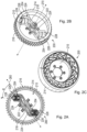
- FIGS 2A and 2B illustrate a schematic side view and a perspective view, respectively, of the hydraulically powered clutch 200, with some modifications to the implementation illustrated in Figure 3 .
- the clutch 200 includes the radial hydraulic conduit 224 extending radially outward from the hydraulic conduit 222 to two hydraulic transformers 254.
- Each hydraulic transformer 254 is used to step hydraulic pressure up from a first hydraulic pressure within the radial hydraulic conduit 224 at a first side of the hydraulic transformer 254 to a second hydraulic pressure at a second side of the hydraulic transformer 254 opposite to its first side, which is in hydraulic communication with a respective hydraulic piston 226.
- the hydraulic transformers 254 are used to step hydraulic pressure up from about 18 bar to about 100 bar.
- An implementation of the hydraulically powered clutch 200 illustrated in Figures 2A and 2B includes two hydraulic pistons 226 and two corresponding engagement elements 228.
- the engagement elements 228 may be cylinders, wheels, spherical elements, or the like.
- the pistons 226 and corresponding engagement elements 228 are oriented obliquely (e.g., at an oblique angle theta) to a radial axis 260, but are rotationally symmetric with respect to the central longitudinal axis 270 of the clutch 200, such that the engagement elements 228 and the forces they exert against the outer rim 214 are balanced.
- FIG. 2C illustrates a schematic perspective view of the hydraulically powered clutch 200, with some modifications to the implementations illustrated in the preceding figures.
- the clutch 200 includes a plurality of hydraulic pistons 226 (twenty shown) and a corresponding plurality of engagement elements 228 (twenty shown).
- the twenty hydraulic pistons 226 and the twenty corresponding engagement elements 228 are oriented obliquely to radial axis 260 but radially symmetric with respect to the central longitudinal axis of the clutch 200, they and the forces they exert against the outer rim 214 are balanced.
- the clutch design is scalable for use with heavy duty vehicles such as agricultural equipment, construction equipment, and the like.
- FIG. 3 a hydraulic circuit for the dual hydraulic actuated piston clutch assembly 1400 is shown.
- the hydraulic circuit includes a variable displacement pump 956 that directs hydraulic fluid from the tank 958 to a first directional control valve 960.
- the first directional control valve 960 controls the flow of the hydraulic fluid that arrives at the hydraulic fluid coupling 922 of the first radial hydraulic piston-actuated torque transfer device 900 using pipe 962.
- the hydraulic fluid passes through the hydraulic fluid coupling 922 and urges the piston 938 and rolling engagement elements 940 towards the output shaft assembly 942 until the rolling engagement elements 940 are in contact with and rotate the output shaft assembly 942.
- the fixed housing 920 of the radial hydraulic piston-actuated torque transfer device 900 is also shown.
- the first radial hydraulic piston-actuated torque transfer device 900 is integrated into the dual hydraulic actuated piston clutch assembly 1400.
- the variable displacement pump 956 of the hydraulic circuit also directs hydraulic fluid from the tank 958 to a second directional control valve 968.
- the second directional control valve 968 controls the flow of the hydraulic fluid through the pipe 970 that arrives at the hydraulic fluid coupling 922 of the second radial hydraulic piston-actuated torque transfer device 900.
- the hydraulic fluid passes through the hydraulic fluid coupling 922 and urges the piston 938 and rolling engagement elements 940 towards the output shaft assembly 944 until the rolling engagement elements 940 are in contact with and rotate the output shaft assembly 944.
- the second radial hydraulic piston-actuated torque transfer device 900 is also integrated into a dual hydraulic actuated piston clutch assembly.
- the hydraulic circuit further includes accumulator 976 that reduces oscillations during actuation of the pistons 912 and associated rolling engagement elements 914 using the hydraulic fluid. Additionally, the accumulator 976 provides a liquid volume that is disposed for fast response during actuation of the radial hydraulic piston-actuated torque transfer device 900. Further, the hydraulic circuit includes a pressure relief valve 978 that protects against pressure overloads in the system.
- An output disc/body 1914 of the torque transfer device includes hydraulic cylinders and slidably engaged hydraulic pistons 1918 (offset radially), which are associated with rolling engagement elements 1920.
- the hydraulic cylinders are connected to a hydraulic circuit via a feeding channel 1916, radial conduit 1930, and axial conduit 1932. Due to the radial offset position of the hydraulic pistons 1918, the hydraulic pistons 1918 are locked, and transfer torque from the input disc 1910 to the output disc 1914 as long the hydraulic pistons 1918 are extended by hydraulic fluid pressure.
- the hydraulic pistons 1918 are equally spaced in a symmetric manner about the inner periphery of the input ring 1910, as shown in Figure 4 .
- additional pistons 1918 and roller engagement elements 1920 may be added around the inner periphery of the input ring 1910, and are actuated simultaneously, without increasing the overall width of the system.
- the supplementation of additional pistons 1918 and roller engagement elements 1920 also assures ease of manufacture scalability.
Landscapes
- Engineering & Computer Science (AREA)
- General Engineering & Computer Science (AREA)
- Mechanical Engineering (AREA)
- Transportation (AREA)
- Chemical & Material Sciences (AREA)
- Combustion & Propulsion (AREA)
- Arrangement And Driving Of Transmission Devices (AREA)
- Motor Power Transmission Devices (AREA)
- Analytical Chemistry (AREA)
- Physics & Mathematics (AREA)
- Fluid Mechanics (AREA)
- Arrangement Or Mounting Of Propulsion Units For Vehicles (AREA)
- Control Of Fluid Gearings (AREA)
- Hydraulic Clutches, Magnetic Clutches, Fluid Clutches, And Fluid Joints (AREA)
Claims (12)
- Système de transfert de couple employant des ensembles de piston hydraulique à décalage radial, le système de transfert de couple comprenant :un arbre d'entrée (202/1702) ;un disque d'entrée (210/1708) accouplé à l'arbre d'entrée (202/1702) pour tourner avec celui-ci ;une bague d'entrée (1710) accouplée au disque d'entrée (210/1708) pour tourner avec celui-ci ;un corps de sortie (1714) situé sensiblement à l'intérieur de la bague d'entrée (1710) pour une rotation autour de l'arbre d'entrée (202/1702),caractérisé par le corps de sortie ayant au moins deux bras de corps de sortie s'étendant radialement vers l'extérieur à partir de l'arbre d'entrée ;une pluralité de vérins hydrauliques (1716) et de pistons associés (1718) situés au niveau d'extrémités radialement extérieures du corps de sortie (1714), chaque piston (1718) étant positionné pour être sélectivement pressé, lorsqu'il est actionné, vers le corps de sortie (1714) et créer une liaison rigide entre l'arbre d'entrée et le corps de sortie ;un passage hydraulique (1730) contenant un fluide hydraulique, le passage hydraulique s'étendant à travers les bras de corps de sortie vers les vérins hydrauliques (1716) et les pistons (1718).
- Système de transfert de couple selon la revendication 1, dans lequel une direction de mouvement de chaque piston est décalée selon un angle d'environ 45 degrés par rapport à une ligne médiane d'au moins l'un des bras de corps de sortie.
- Système de transfert de couple selon la revendication 1, comprenant en outre : des éléments de mise en prise de rouleau (1920) situés vers l'extérieur des pistons (1918), dans lequel le fluide hydraulique presse les éléments de mise en prise de rouleau en prise avec la bague d'entrée (1910), la mise en prise des éléments de mise en prise de rouleau (1920) avec la bague d'entrée amenant le corps de sortie à se déplacer à l'unisson avec la bague d'entrée.
- Système de transfert de couple selon la revendication 3, dans lequel les éléments de mise en prise de rouleau (1920) sont cylindriques.
- Système de transfert de couple selon la revendication 1, dans lequel les bras de corps de sortie sont disposés angulairement l'un par rapport à l'autre à des angles sensiblement égaux.
- Système de transfert de couple selon la revendication 1, dans lequel au moins deux vérins hydrauliques (1716) et des pistons associés (1718) de la pluralité de vérins hydrauliques et de pistons associés sont disposés au niveau d'une extrémité radialement extérieure de chacun des bras de corps de sortie.
- Système de transfert de couple selon la revendication 1, comprenant en outre : une bague d'engrenage (216) s'étendant radialement vers l'extérieur depuis la bague d'entrée pour une mise en prise sélective avec un moteur/générateur électrique.
- Système de transfert de couple selon la revendication 1, comprenant en outre : un système hydraulique associé de manière opérationnelle aux vérins hydrauliques et aux pistons, dans lequel le système hydraulique permet un actionnement et un désactionnement des pistons dans les vérins hydrauliques, dans lequel l'actionnement des pistons dans les vérins hydrauliques accouple l'arbre d'entrée au corps de sortie et le désactionnement des pistons dans les vérins hydrauliques désaccouple l'arbre d'entrée du corps de sortie.
- Système de transfert de couple selon la revendication 1, comprenant en outre : une pompe hydraulique à cylindrée variable (1748) qui est associée de manière opérationnelle à chaque cylindre hydraulique et piston associé.
- Système de transfert de couple selon la revendication 9, comprenant en outre des soupapes de commande directionnelles (960, 968) qui utilisent le fluide hydraulique pour presser sélectivement chaque piston à être poussé vers le corps de sortie lorsqu'il est actionné.
- Système de transfert de couple selon la revendication 10, comprenant en outre un accumulateur hydraulique (1746) qui est associé de manière opérationnelle à la pompe hydraulique à cylindrée variable (1748) et aux soupapes de commande directionnelles, dans lequel l'accumulateur hydraulique (1746) fournit une commande intermédiaire du système de transfert de couple en amortissant des oscillations dans le système de transfert de couple pendant l'actionnement.
- Système de transfert de couple selon la revendication 1, dans lequel le système de transfert de couple est incorporé dans une transmission automobile (100).
Applications Claiming Priority (12)
| Application Number | Priority Date | Filing Date | Title |
|---|---|---|---|
| US201662498349P | 2016-12-21 | 2016-12-21 | |
| US201715731271A | 2017-05-15 | 2017-05-15 | |
| US201715731267A | 2017-05-15 | 2017-05-15 | |
| US201715731383A | 2017-06-05 | 2017-06-05 | |
| US201762605291P | 2017-08-07 | 2017-08-07 | |
| US201762605283P | 2017-08-07 | 2017-08-07 | |
| US201762606522P | 2017-09-26 | 2017-09-26 | |
| US201762584650P | 2017-11-10 | 2017-11-10 | |
| US201762598364P | 2017-12-13 | 2017-12-13 | |
| US201762598366P | 2017-12-13 | 2017-12-13 | |
| ROA201701155A RO133437A2 (ro) | 2017-12-20 | 2017-12-20 | Ambreiaje, cutii de viteze, sisteme de recuperare a energiei şi transmisii hidraulice |
| PCT/US2017/068042 WO2018119326A1 (fr) | 2016-12-21 | 2017-12-21 | Embrayages hydrauliques, boîtes de vitesses, transmissions et systèmes de récupération d'énergie |
Publications (3)
| Publication Number | Publication Date |
|---|---|
| EP3558736A1 EP3558736A1 (fr) | 2019-10-30 |
| EP3558736A4 EP3558736A4 (fr) | 2020-12-16 |
| EP3558736B1 true EP3558736B1 (fr) | 2024-04-17 |
Family
ID=62627565
Family Applications (1)
| Application Number | Title | Priority Date | Filing Date |
|---|---|---|---|
| EP17883710.0A Active EP3558736B1 (fr) | 2016-12-21 | 2017-12-21 | Embrayages hydrauliques, boîtes de vitesses, transmissions et systèmes de récupération d'énergie |
Country Status (5)
| Country | Link |
|---|---|
| US (2) | US11441617B2 (fr) |
| EP (1) | EP3558736B1 (fr) |
| JP (1) | JP2020507041A (fr) |
| CA (1) | CA3048231A1 (fr) |
| WO (1) | WO2018119326A1 (fr) |
Families Citing this family (9)
| Publication number | Priority date | Publication date | Assignee | Title |
|---|---|---|---|---|
| US8991840B2 (en) * | 2013-03-14 | 2015-03-31 | Oshkosh Defense, Llc | Load dependent damper for a vehicle suspension system |
| US11448268B2 (en) | 2018-08-03 | 2022-09-20 | A & A International, Llc | System and method for hydraulic transformer clutches |
| IT201900018701A1 (it) * | 2019-10-14 | 2021-04-14 | Ind Saleri Italo Spa | Assieme di gestione termica di un veicolo |
| IT201900018710A1 (it) * | 2019-10-14 | 2021-04-14 | Ind Saleri Italo Spa | Assieme di gestione termica di un veicolo |
| IT201900018704A1 (it) * | 2019-10-14 | 2021-04-14 | Ind Saleri Italo Spa | Dispositivo di comando fluidico di un veicolo |
| WO2021108596A1 (fr) * | 2019-11-26 | 2021-06-03 | A & A International, Llc | Système et procédé d'embrayage de transformateur hydraulique |
| GB202001018D0 (en) * | 2020-01-24 | 2020-03-11 | Evectek Ltd | An integrated wheel hub and pump/motor unit |
| CN111516478A (zh) * | 2020-03-23 | 2020-08-11 | 潍柴动力股份有限公司 | 车辆的传动系统及车辆 |
| CN119568904B (zh) * | 2025-02-07 | 2025-04-18 | 山西海通实业有限公司 | 一种煤矿井下用液压行走装置 |
Family Cites Families (46)
| Publication number | Priority date | Publication date | Assignee | Title |
|---|---|---|---|---|
| GB816945A (en) | 1956-05-31 | 1959-07-22 | John Malcolm Robson | Improvements in or relating to transmission equipment for use in ships, boats or other vehicles |
| US1372984A (en) * | 1921-03-29 | Fluid-clutch | ||
| US2255738A (en) | 1938-01-13 | 1941-09-09 | Jean A H Barkeij | Power transmission |
| US2436947A (en) | 1943-11-23 | 1948-03-02 | Elox Soc | Overload release clutch |
| US2719620A (en) * | 1951-01-06 | 1955-10-04 | Mcdonald & Eide Inc | Transversely engaged fluid operated clutch |
| GB833630A (en) | 1955-06-29 | 1960-04-27 | John Alec Cooper | Infinitely-variable transmission coupling |
| US5094331A (en) | 1988-03-18 | 1992-03-10 | Honda Giken Kogyo Kabushiki Kaisha | Wet-type multiplate clutch |
| US5495912A (en) | 1994-06-03 | 1996-03-05 | The United States Of America As Represented By The Administrator Of The U.S. Environmental Protection Agency | Hybrid powertrain vehicle |
| US5638929A (en) | 1995-04-06 | 1997-06-17 | Hyundai Motor Company, Ltd. | Controllable one-way clutch for a vehicle |
| US5799562A (en) * | 1996-03-13 | 1998-09-01 | Weinberg; Morgan W. | Regenerative braking method and apparatus therefor |
| CN2290495Y (zh) | 1997-02-25 | 1998-09-09 | 郎静明 | 汽车离合器液压自动控制装置 |
| US7198587B2 (en) | 2003-12-16 | 2007-04-03 | General Motors Corporation | Transmission with selectable braking one-way clutch |
| US7588133B2 (en) | 2004-09-01 | 2009-09-15 | Magna Powertrain Usa, Inc. | Clutch control system for power transmission devices |
| US7097019B2 (en) | 2004-09-01 | 2006-08-29 | Magna Powertrain Usa, Inc. | Low power modulating clutch control system with electromagnetic actuator |
| US7506740B2 (en) | 2004-09-01 | 2009-03-24 | Magna Powertrain Usa, Inc. | Power transmission device with clutch control system |
| US7182194B2 (en) | 2004-09-01 | 2007-02-27 | Magna Powertrain Usa, Inc. | Low power modulating clutch control system with combination accumulator and piston actuator |
| US8132868B2 (en) * | 2004-12-17 | 2012-03-13 | Walker Frank H | Hydraulic regenerative braking system for a vehicle |
| WO2008033378A1 (fr) | 2006-09-12 | 2008-03-20 | Purdue Research Foundation | Transmission à répartition du couple avec récupération d'énergie |
| US7744499B2 (en) * | 2007-01-22 | 2010-06-29 | Southwest Research Institute | Hydro-mechanical transmission |
| US8494738B2 (en) | 2008-09-09 | 2013-07-23 | GM Global Technology Operations LLC | Control of selectable one-way clutch in a transmission |
| US8306709B2 (en) | 2008-09-09 | 2012-11-06 | GM Global Technology Operations LLC | Engagement of selectable one-way clutch or mechanical diode by active engine speed control |
| US8087733B2 (en) * | 2008-12-09 | 2012-01-03 | Développement Effenco Inc. | Braking energy recovery system for a vehicle and vehicle equipped with the same |
| US8302720B2 (en) * | 2009-01-28 | 2012-11-06 | Robert Bosch Gmbh | Energy storage system for a hybrid vehicle |
| JP2012527588A (ja) * | 2009-05-19 | 2012-11-08 | ユゥティ グローバル カンパニィ リミテッド | 多段自動変速機 |
| US8622859B2 (en) | 2009-06-10 | 2014-01-07 | Czero Holding Company, Llc | Systems and methods for hybridization of a motor vehicle using hydraulic components |
| US8844392B2 (en) | 2010-06-09 | 2014-09-30 | Gm Global Technology Operations, Llc | Electro-hydraulic and electro-mechanical control system for a dual clutch transmission |
| EP2591249B1 (fr) * | 2010-07-08 | 2015-03-11 | Parker-Hannifin Corporation | Moteur à répartition de puissance hydraulique à assistance de couple améliorée |
| US8512204B2 (en) | 2010-10-20 | 2013-08-20 | GM Global Technology Operations LLC | Method and apparatus effecting torque transfer through a transmission during engine autostop and autostart events |
| US8622186B2 (en) | 2010-12-03 | 2014-01-07 | GM Global Technology Operations LLC | Method of operation of a selectable one way clutch selection mechanism |
| JP5776892B2 (ja) | 2011-07-13 | 2015-09-09 | スズキ株式会社 | ハイブリッド駆動装置 |
| US8771138B2 (en) * | 2011-09-16 | 2014-07-08 | Eaton Corporation | Hybrid hydraulic drive system architecture |
| CN103104408B (zh) * | 2011-10-12 | 2018-05-15 | 曲言明 | 振荡活塞式波浪发电方法及系统 |
| US20160053879A1 (en) * | 2012-05-02 | 2016-02-25 | Parker-Hannifin Corporation | Pump control method and system |
| JP6045409B2 (ja) | 2013-03-13 | 2016-12-14 | 日立オートモティブシステムズ株式会社 | オイル供給装置 |
| AU2013392646B2 (en) | 2013-06-17 | 2016-04-21 | Allison Transmission, Inc. | System and method for actuating a mechanical diode clutch assembly |
| WO2014209933A1 (fr) | 2013-06-25 | 2014-12-31 | Parker-Hannifin Corporation | Architectures hybrides à configuration hydrostatique-hydraulique parallèle |
| JP6135431B2 (ja) | 2013-09-30 | 2017-05-31 | アイシン・エィ・ダブリュ株式会社 | 摩擦係合要素 |
| US9428049B2 (en) | 2014-02-26 | 2016-08-30 | Deere & Company | Multi-mode power trains with direct-drive lock-up |
| GB2530823A (en) | 2014-05-16 | 2016-04-06 | Flybrid Automotive Ltd | Controlled cooling of a frictional engagement device in an energy recovery system |
| US9803749B2 (en) * | 2015-08-05 | 2017-10-31 | Caterpillar Inc. | Hydraulically coupled multi-variator actuator |
| CA3037295A1 (fr) | 2016-10-28 | 2018-05-03 | A & A International, Llc | Systeme de propulsion hydraulique thermique |
| US10337564B2 (en) | 2016-12-22 | 2019-07-02 | Schaeffler Technologies AG & Co. KG | Segmented wedge clutch with stepped retaining spring |
| US10378596B2 (en) | 2017-02-21 | 2019-08-13 | Schaeffler Technologies AG & Co. KG | Wedge clutch with anti-expansion retainer |
| DE102017110165B3 (de) | 2017-05-11 | 2018-09-13 | Schaeffler Technologies AG & Co. KG | Verfahren zur Ansteuerung einer Kupplung mit einem Kupplungsbetätigungssystem und ein Kupplungsbetätigungssystem |
| WO2019183590A1 (fr) | 2018-03-22 | 2019-09-26 | A & A International, Llc | Embrayages hydrauliques, boîtes de vitesses, transmissions, systèmes de récupération d'énergie, embrayages unidirectionnels mécaniques, diodes mécaniques et embrayages à friction variable |
| US11448268B2 (en) | 2018-08-03 | 2022-09-20 | A & A International, Llc | System and method for hydraulic transformer clutches |
-
2017
- 2017-12-21 EP EP17883710.0A patent/EP3558736B1/fr active Active
- 2017-12-21 CA CA3048231A patent/CA3048231A1/fr not_active Abandoned
- 2017-12-21 WO PCT/US2017/068042 patent/WO2018119326A1/fr not_active Ceased
- 2017-12-21 US US16/472,748 patent/US11441617B2/en active Active
- 2017-12-21 JP JP2019555731A patent/JP2020507041A/ja active Pending
-
2022
- 2022-08-03 US US17/880,537 patent/US20220373041A1/en not_active Abandoned
Also Published As
| Publication number | Publication date |
|---|---|
| EP3558736A1 (fr) | 2019-10-30 |
| EP3558736A4 (fr) | 2020-12-16 |
| US20220373041A1 (en) | 2022-11-24 |
| CA3048231A1 (fr) | 2018-06-28 |
| WO2018119326A1 (fr) | 2018-06-28 |
| US20210129805A1 (en) | 2021-05-06 |
| US11441617B2 (en) | 2022-09-13 |
| JP2020507041A (ja) | 2020-03-05 |
Similar Documents
| Publication | Publication Date | Title |
|---|---|---|
| EP3558736B1 (fr) | Embrayages hydrauliques, boîtes de vitesses, transmissions et systèmes de récupération d'énergie | |
| CN102606705A (zh) | 具有锁止离合器的扭矩变换器 | |
| CN107631022A (zh) | 具有液压致动活塞和锁紧装置的离合器组件 | |
| CN106274465B (zh) | 用于马达和制动控制的具有多功能致动器的驱动组件 | |
| CN100396950C (zh) | 离合器 | |
| US11686377B2 (en) | Torque converter lockup clutch structure | |
| US11313419B2 (en) | Clutched power transmitting device with reduced lag time for actuation | |
| US7210376B2 (en) | Device for transmitting torque between two rotatable, coaxial schaft members | |
| CN105605184A (zh) | 带有方向选择机构的无级变速器 | |
| WO2014151075A1 (fr) | Dispositif de direction générant un couple | |
| US8960394B2 (en) | Thrust activated friction one-way clutch | |
| CN116648385A (zh) | 制动系统 | |
| US9890855B2 (en) | Actuating device with a master cylinder actuatable by a gear selector drum for actuating the clutch | |
| CN116601059A (zh) | 制动系统 | |
| US10378621B2 (en) | Continuously variable transmission | |
| US20070284206A1 (en) | Pilot plate torque transmitting assembly for a torque converter | |
| EP2765061B1 (fr) | Système de pumpe hydraulique d'une direction assitée d'urgence | |
| CN104315027A (zh) | 一种锁止离合器 | |
| US20230003263A1 (en) | System and method for hydraulic transformer clutches | |
| US20060258493A1 (en) | Pressure supply to a continuously adjustable automatic transmission in particular a clasping transmission | |
| KR102240176B1 (ko) | 듀얼 클러치 장치 | |
| DE102013209478A1 (de) | Schrägscheibenmaschine | |
| WO2017210194A1 (fr) | Transmission à variation continue |
Legal Events
| Date | Code | Title | Description |
|---|---|---|---|
| STAA | Information on the status of an ep patent application or granted ep patent |
Free format text: STATUS: THE INTERNATIONAL PUBLICATION HAS BEEN MADE |
|
| PUAI | Public reference made under article 153(3) epc to a published international application that has entered the european phase |
Free format text: ORIGINAL CODE: 0009012 |
|
| STAA | Information on the status of an ep patent application or granted ep patent |
Free format text: STATUS: REQUEST FOR EXAMINATION WAS MADE |
|
| 17P | Request for examination filed |
Effective date: 20190628 |
|
| AK | Designated contracting states |
Kind code of ref document: A1 Designated state(s): AL AT BE BG CH CY CZ DE DK EE ES FI FR GB GR HR HU IE IS IT LI LT LU LV MC MK MT NL NO PL PT RO RS SE SI SK SM TR |
|
| AX | Request for extension of the european patent |
Extension state: BA ME |
|
| DAV | Request for validation of the european patent (deleted) | ||
| DAX | Request for extension of the european patent (deleted) | ||
| A4 | Supplementary search report drawn up and despatched |
Effective date: 20201117 |
|
| RIC1 | Information provided on ipc code assigned before grant |
Ipc: F16D 31/02 20060101ALI20201111BHEP Ipc: B60K 6/08 20060101ALI20201111BHEP Ipc: F16D 25/10 20060101ALI20201111BHEP Ipc: F16D 25/00 20060101ALI20201111BHEP Ipc: B60K 6/12 20060101AFI20201111BHEP Ipc: F16D 25/06 20060101ALI20201111BHEP |
|
| STAA | Information on the status of an ep patent application or granted ep patent |
Free format text: STATUS: EXAMINATION IS IN PROGRESS |
|
| 17Q | First examination report despatched |
Effective date: 20220316 |
|
| GRAP | Despatch of communication of intention to grant a patent |
Free format text: ORIGINAL CODE: EPIDOSNIGR1 |
|
| STAA | Information on the status of an ep patent application or granted ep patent |
Free format text: STATUS: GRANT OF PATENT IS INTENDED |
|
| INTG | Intention to grant announced |
Effective date: 20230731 |
|
| GRAS | Grant fee paid |
Free format text: ORIGINAL CODE: EPIDOSNIGR3 |
|
| GRAA | (expected) grant |
Free format text: ORIGINAL CODE: 0009210 |
|
| STAA | Information on the status of an ep patent application or granted ep patent |
Free format text: STATUS: THE PATENT HAS BEEN GRANTED |
|
| AK | Designated contracting states |
Kind code of ref document: B1 Designated state(s): AL AT BE BG CH CY CZ DE DK EE ES FI FR GB GR HR HU IE IS IT LI LT LU LV MC MK MT NL NO PL PT RO RS SE SI SK SM TR |
|
| REG | Reference to a national code |
Ref country code: GB Ref legal event code: FG4D |
|
| REG | Reference to a national code |
Ref country code: CH Ref legal event code: EP |
|
| REG | Reference to a national code |
Ref country code: DE Ref legal event code: R096 Ref document number: 602017081171 Country of ref document: DE |
|
| REG | Reference to a national code |
Ref country code: IE Ref legal event code: FG4D |
|
| REG | Reference to a national code |
Ref country code: LT Ref legal event code: MG9D |
|
| REG | Reference to a national code |
Ref country code: NL Ref legal event code: MP Effective date: 20240417 |
|
| REG | Reference to a national code |
Ref country code: AT Ref legal event code: MK05 Ref document number: 1676937 Country of ref document: AT Kind code of ref document: T Effective date: 20240417 |
|
| PG25 | Lapsed in a contracting state [announced via postgrant information from national office to epo] |
Ref country code: NL Free format text: LAPSE BECAUSE OF FAILURE TO SUBMIT A TRANSLATION OF THE DESCRIPTION OR TO PAY THE FEE WITHIN THE PRESCRIBED TIME-LIMIT Effective date: 20240417 |
|
| PG25 | Lapsed in a contracting state [announced via postgrant information from national office to epo] |
Ref country code: NL Free format text: LAPSE BECAUSE OF FAILURE TO SUBMIT A TRANSLATION OF THE DESCRIPTION OR TO PAY THE FEE WITHIN THE PRESCRIBED TIME-LIMIT Effective date: 20240417 |
|
| PG25 | Lapsed in a contracting state [announced via postgrant information from national office to epo] |
Ref country code: IS Free format text: LAPSE BECAUSE OF FAILURE TO SUBMIT A TRANSLATION OF THE DESCRIPTION OR TO PAY THE FEE WITHIN THE PRESCRIBED TIME-LIMIT Effective date: 20240817 |
|
| PG25 | Lapsed in a contracting state [announced via postgrant information from national office to epo] |
Ref country code: BG Free format text: LAPSE BECAUSE OF FAILURE TO SUBMIT A TRANSLATION OF THE DESCRIPTION OR TO PAY THE FEE WITHIN THE PRESCRIBED TIME-LIMIT Effective date: 20240417 |
|
| PG25 | Lapsed in a contracting state [announced via postgrant information from national office to epo] |
Ref country code: HR Free format text: LAPSE BECAUSE OF FAILURE TO SUBMIT A TRANSLATION OF THE DESCRIPTION OR TO PAY THE FEE WITHIN THE PRESCRIBED TIME-LIMIT Effective date: 20240417 Ref country code: FI Free format text: LAPSE BECAUSE OF FAILURE TO SUBMIT A TRANSLATION OF THE DESCRIPTION OR TO PAY THE FEE WITHIN THE PRESCRIBED TIME-LIMIT Effective date: 20240417 |
|
| PG25 | Lapsed in a contracting state [announced via postgrant information from national office to epo] |
Ref country code: GR Free format text: LAPSE BECAUSE OF FAILURE TO SUBMIT A TRANSLATION OF THE DESCRIPTION OR TO PAY THE FEE WITHIN THE PRESCRIBED TIME-LIMIT Effective date: 20240718 |
|
| PG25 | Lapsed in a contracting state [announced via postgrant information from national office to epo] |
Ref country code: PT Free format text: LAPSE BECAUSE OF FAILURE TO SUBMIT A TRANSLATION OF THE DESCRIPTION OR TO PAY THE FEE WITHIN THE PRESCRIBED TIME-LIMIT Effective date: 20240819 |
|
| PG25 | Lapsed in a contracting state [announced via postgrant information from national office to epo] |
Ref country code: ES Free format text: LAPSE BECAUSE OF FAILURE TO SUBMIT A TRANSLATION OF THE DESCRIPTION OR TO PAY THE FEE WITHIN THE PRESCRIBED TIME-LIMIT Effective date: 20240417 |
|
| PG25 | Lapsed in a contracting state [announced via postgrant information from national office to epo] |
Ref country code: AT Free format text: LAPSE BECAUSE OF FAILURE TO SUBMIT A TRANSLATION OF THE DESCRIPTION OR TO PAY THE FEE WITHIN THE PRESCRIBED TIME-LIMIT Effective date: 20240417 |
|
| PG25 | Lapsed in a contracting state [announced via postgrant information from national office to epo] |
Ref country code: PL Free format text: LAPSE BECAUSE OF FAILURE TO SUBMIT A TRANSLATION OF THE DESCRIPTION OR TO PAY THE FEE WITHIN THE PRESCRIBED TIME-LIMIT Effective date: 20240417 |
|
| PG25 | Lapsed in a contracting state [announced via postgrant information from national office to epo] |
Ref country code: LV Free format text: LAPSE BECAUSE OF FAILURE TO SUBMIT A TRANSLATION OF THE DESCRIPTION OR TO PAY THE FEE WITHIN THE PRESCRIBED TIME-LIMIT Effective date: 20240417 |
|
| PG25 | Lapsed in a contracting state [announced via postgrant information from national office to epo] |
Ref country code: PT Free format text: LAPSE BECAUSE OF FAILURE TO SUBMIT A TRANSLATION OF THE DESCRIPTION OR TO PAY THE FEE WITHIN THE PRESCRIBED TIME-LIMIT Effective date: 20240819 Ref country code: PL Free format text: LAPSE BECAUSE OF FAILURE TO SUBMIT A TRANSLATION OF THE DESCRIPTION OR TO PAY THE FEE WITHIN THE PRESCRIBED TIME-LIMIT Effective date: 20240417 Ref country code: NO Free format text: LAPSE BECAUSE OF FAILURE TO SUBMIT A TRANSLATION OF THE DESCRIPTION OR TO PAY THE FEE WITHIN THE PRESCRIBED TIME-LIMIT Effective date: 20240717 Ref country code: LV Free format text: LAPSE BECAUSE OF FAILURE TO SUBMIT A TRANSLATION OF THE DESCRIPTION OR TO PAY THE FEE WITHIN THE PRESCRIBED TIME-LIMIT Effective date: 20240417 Ref country code: IS Free format text: LAPSE BECAUSE OF FAILURE TO SUBMIT A TRANSLATION OF THE DESCRIPTION OR TO PAY THE FEE WITHIN THE PRESCRIBED TIME-LIMIT Effective date: 20240817 Ref country code: HR Free format text: LAPSE BECAUSE OF FAILURE TO SUBMIT A TRANSLATION OF THE DESCRIPTION OR TO PAY THE FEE WITHIN THE PRESCRIBED TIME-LIMIT Effective date: 20240417 Ref country code: GR Free format text: LAPSE BECAUSE OF FAILURE TO SUBMIT A TRANSLATION OF THE DESCRIPTION OR TO PAY THE FEE WITHIN THE PRESCRIBED TIME-LIMIT Effective date: 20240718 Ref country code: FI Free format text: LAPSE BECAUSE OF FAILURE TO SUBMIT A TRANSLATION OF THE DESCRIPTION OR TO PAY THE FEE WITHIN THE PRESCRIBED TIME-LIMIT Effective date: 20240417 Ref country code: ES Free format text: LAPSE BECAUSE OF FAILURE TO SUBMIT A TRANSLATION OF THE DESCRIPTION OR TO PAY THE FEE WITHIN THE PRESCRIBED TIME-LIMIT Effective date: 20240417 Ref country code: BG Free format text: LAPSE BECAUSE OF FAILURE TO SUBMIT A TRANSLATION OF THE DESCRIPTION OR TO PAY THE FEE WITHIN THE PRESCRIBED TIME-LIMIT Effective date: 20240417 Ref country code: AT Free format text: LAPSE BECAUSE OF FAILURE TO SUBMIT A TRANSLATION OF THE DESCRIPTION OR TO PAY THE FEE WITHIN THE PRESCRIBED TIME-LIMIT Effective date: 20240417 Ref country code: RS Free format text: LAPSE BECAUSE OF FAILURE TO SUBMIT A TRANSLATION OF THE DESCRIPTION OR TO PAY THE FEE WITHIN THE PRESCRIBED TIME-LIMIT Effective date: 20240717 |
|
| PG25 | Lapsed in a contracting state [announced via postgrant information from national office to epo] |
Ref country code: DK Free format text: LAPSE BECAUSE OF FAILURE TO SUBMIT A TRANSLATION OF THE DESCRIPTION OR TO PAY THE FEE WITHIN THE PRESCRIBED TIME-LIMIT Effective date: 20240417 |
|
| REG | Reference to a national code |
Ref country code: DE Ref legal event code: R097 Ref document number: 602017081171 Country of ref document: DE |
|
| PG25 | Lapsed in a contracting state [announced via postgrant information from national office to epo] |
Ref country code: EE Free format text: LAPSE BECAUSE OF FAILURE TO SUBMIT A TRANSLATION OF THE DESCRIPTION OR TO PAY THE FEE WITHIN THE PRESCRIBED TIME-LIMIT Effective date: 20240417 |
|
| PG25 | Lapsed in a contracting state [announced via postgrant information from national office to epo] |
Ref country code: CZ Free format text: LAPSE BECAUSE OF FAILURE TO SUBMIT A TRANSLATION OF THE DESCRIPTION OR TO PAY THE FEE WITHIN THE PRESCRIBED TIME-LIMIT Effective date: 20240417 |
|
| PG25 | Lapsed in a contracting state [announced via postgrant information from national office to epo] |
Ref country code: SK Free format text: LAPSE BECAUSE OF FAILURE TO SUBMIT A TRANSLATION OF THE DESCRIPTION OR TO PAY THE FEE WITHIN THE PRESCRIBED TIME-LIMIT Effective date: 20240417 Ref country code: RO Free format text: LAPSE BECAUSE OF FAILURE TO SUBMIT A TRANSLATION OF THE DESCRIPTION OR TO PAY THE FEE WITHIN THE PRESCRIBED TIME-LIMIT Effective date: 20240417 |
|
| PG25 | Lapsed in a contracting state [announced via postgrant information from national office to epo] |
Ref country code: SM Free format text: LAPSE BECAUSE OF FAILURE TO SUBMIT A TRANSLATION OF THE DESCRIPTION OR TO PAY THE FEE WITHIN THE PRESCRIBED TIME-LIMIT Effective date: 20240417 |
|
| PG25 | Lapsed in a contracting state [announced via postgrant information from national office to epo] |
Ref country code: SM Free format text: LAPSE BECAUSE OF FAILURE TO SUBMIT A TRANSLATION OF THE DESCRIPTION OR TO PAY THE FEE WITHIN THE PRESCRIBED TIME-LIMIT Effective date: 20240417 Ref country code: SK Free format text: LAPSE BECAUSE OF FAILURE TO SUBMIT A TRANSLATION OF THE DESCRIPTION OR TO PAY THE FEE WITHIN THE PRESCRIBED TIME-LIMIT Effective date: 20240417 Ref country code: RO Free format text: LAPSE BECAUSE OF FAILURE TO SUBMIT A TRANSLATION OF THE DESCRIPTION OR TO PAY THE FEE WITHIN THE PRESCRIBED TIME-LIMIT Effective date: 20240417 Ref country code: EE Free format text: LAPSE BECAUSE OF FAILURE TO SUBMIT A TRANSLATION OF THE DESCRIPTION OR TO PAY THE FEE WITHIN THE PRESCRIBED TIME-LIMIT Effective date: 20240417 Ref country code: DK Free format text: LAPSE BECAUSE OF FAILURE TO SUBMIT A TRANSLATION OF THE DESCRIPTION OR TO PAY THE FEE WITHIN THE PRESCRIBED TIME-LIMIT Effective date: 20240417 Ref country code: CZ Free format text: LAPSE BECAUSE OF FAILURE TO SUBMIT A TRANSLATION OF THE DESCRIPTION OR TO PAY THE FEE WITHIN THE PRESCRIBED TIME-LIMIT Effective date: 20240417 |
|
| PG25 | Lapsed in a contracting state [announced via postgrant information from national office to epo] |
Ref country code: IT Free format text: LAPSE BECAUSE OF FAILURE TO SUBMIT A TRANSLATION OF THE DESCRIPTION OR TO PAY THE FEE WITHIN THE PRESCRIBED TIME-LIMIT Effective date: 20240417 |
|
| PLBE | No opposition filed within time limit |
Free format text: ORIGINAL CODE: 0009261 |
|
| STAA | Information on the status of an ep patent application or granted ep patent |
Free format text: STATUS: NO OPPOSITION FILED WITHIN TIME LIMIT |
|
| 26N | No opposition filed |
Effective date: 20250120 |
|
| PG25 | Lapsed in a contracting state [announced via postgrant information from national office to epo] |
Ref country code: SI Free format text: LAPSE BECAUSE OF FAILURE TO SUBMIT A TRANSLATION OF THE DESCRIPTION OR TO PAY THE FEE WITHIN THE PRESCRIBED TIME-LIMIT Effective date: 20240417 |
|
| PG25 | Lapsed in a contracting state [announced via postgrant information from national office to epo] |
Ref country code: MC Free format text: LAPSE BECAUSE OF FAILURE TO SUBMIT A TRANSLATION OF THE DESCRIPTION OR TO PAY THE FEE WITHIN THE PRESCRIBED TIME-LIMIT Effective date: 20240417 |
|
| REG | Reference to a national code |
Ref country code: CH Ref legal event code: PL |
|
| PG25 | Lapsed in a contracting state [announced via postgrant information from national office to epo] |
Ref country code: LU Free format text: LAPSE BECAUSE OF NON-PAYMENT OF DUE FEES Effective date: 20241221 |
|
| PG25 | Lapsed in a contracting state [announced via postgrant information from national office to epo] |
Ref country code: SE Free format text: LAPSE BECAUSE OF FAILURE TO SUBMIT A TRANSLATION OF THE DESCRIPTION OR TO PAY THE FEE WITHIN THE PRESCRIBED TIME-LIMIT Effective date: 20240417 |
|
| REG | Reference to a national code |
Ref country code: BE Ref legal event code: MM Effective date: 20241231 |
|
| PG25 | Lapsed in a contracting state [announced via postgrant information from national office to epo] |
Ref country code: BE Free format text: LAPSE BECAUSE OF NON-PAYMENT OF DUE FEES Effective date: 20241231 |
|
| PG25 | Lapsed in a contracting state [announced via postgrant information from national office to epo] |
Ref country code: FR Free format text: LAPSE BECAUSE OF NON-PAYMENT OF DUE FEES Effective date: 20241231 |
|
| PG25 | Lapsed in a contracting state [announced via postgrant information from national office to epo] |
Ref country code: CH Free format text: LAPSE BECAUSE OF NON-PAYMENT OF DUE FEES Effective date: 20241231 |
|
| PG25 | Lapsed in a contracting state [announced via postgrant information from national office to epo] |
Ref country code: IE Free format text: LAPSE BECAUSE OF NON-PAYMENT OF DUE FEES Effective date: 20241221 |
|
| PGFP | Annual fee paid to national office [announced via postgrant information from national office to epo] |
Ref country code: GB Payment date: 20251229 Year of fee payment: 9 |
|
| PGFP | Annual fee paid to national office [announced via postgrant information from national office to epo] |
Ref country code: DE Payment date: 20251229 Year of fee payment: 9 |