EP3559536B1 - Kamerasteuerungsverfahren und vorrichtung - Google Patents
Kamerasteuerungsverfahren und vorrichtung Download PDFInfo
- Publication number
- EP3559536B1 EP3559536B1 EP17883468.5A EP17883468A EP3559536B1 EP 3559536 B1 EP3559536 B1 EP 3559536B1 EP 17883468 A EP17883468 A EP 17883468A EP 3559536 B1 EP3559536 B1 EP 3559536B1
- Authority
- EP
- European Patent Office
- Prior art keywords
- motor
- coupling member
- elongate
- channel
- component
- Prior art date
- Legal status (The legal status is an assumption and is not a legal conclusion. Google has not performed a legal analysis and makes no representation as to the accuracy of the status listed.)
- Active
Links
Images


Classifications
-
- G—PHYSICS
- G03—PHOTOGRAPHY; CINEMATOGRAPHY; ANALOGOUS TECHNIQUES USING WAVES OTHER THAN OPTICAL WAVES; ELECTROGRAPHY; HOLOGRAPHY
- G03B—APPARATUS OR ARRANGEMENTS FOR TAKING PHOTOGRAPHS OR FOR PROJECTING OR VIEWING THEM; APPARATUS OR ARRANGEMENTS EMPLOYING ANALOGOUS TECHNIQUES USING WAVES OTHER THAN OPTICAL WAVES; ACCESSORIES THEREFOR
- G03B17/00—Details of cameras or camera bodies; Accessories therefor
- G03B17/56—Accessories
- G03B17/561—Support related camera accessories
-
- F—MECHANICAL ENGINEERING; LIGHTING; HEATING; WEAPONS; BLASTING
- F16—ENGINEERING ELEMENTS AND UNITS; GENERAL MEASURES FOR PRODUCING AND MAINTAINING EFFECTIVE FUNCTIONING OF MACHINES OR INSTALLATIONS; THERMAL INSULATION IN GENERAL
- F16B—DEVICES FOR FASTENING OR SECURING CONSTRUCTIONAL ELEMENTS OR MACHINE PARTS TOGETHER, e.g. NAILS, BOLTS, CIRCLIPS, CLAMPS, CLIPS OR WEDGES; JOINTS OR JOINTING
- F16B2/00—Friction-grip releasable fastenings
- F16B2/02—Clamps, i.e. with gripping action effected by positive means other than the inherent resistance to deformation of the material of the fastening
- F16B2/18—Clamps, i.e. with gripping action effected by positive means other than the inherent resistance to deformation of the material of the fastening using cams, levers, eccentrics, or toggles
- F16B2/185—Clamps, i.e. with gripping action effected by positive means other than the inherent resistance to deformation of the material of the fastening using cams, levers, eccentrics, or toggles using levers
-
- F—MECHANICAL ENGINEERING; LIGHTING; HEATING; WEAPONS; BLASTING
- F16—ENGINEERING ELEMENTS AND UNITS; GENERAL MEASURES FOR PRODUCING AND MAINTAINING EFFECTIVE FUNCTIONING OF MACHINES OR INSTALLATIONS; THERMAL INSULATION IN GENERAL
- F16M—FRAMES, CASINGS OR BEDS OF ENGINES, MACHINES OR APPARATUS, NOT SPECIFIC TO ENGINES, MACHINES OR APPARATUS PROVIDED FOR ELSEWHERE; STANDS; SUPPORTS
- F16M11/00—Stands or trestles as supports for apparatus or articles placed thereon ; Stands for scientific apparatus such as gravitational force meters
- F16M11/20—Undercarriages with or without wheels
- F16M11/2085—Undercarriages with or without wheels comprising means allowing sideward adjustment, i.e. left-right translation of the head relatively to the undercarriage
-
- F—MECHANICAL ENGINEERING; LIGHTING; HEATING; WEAPONS; BLASTING
- F16—ENGINEERING ELEMENTS AND UNITS; GENERAL MEASURES FOR PRODUCING AND MAINTAINING EFFECTIVE FUNCTIONING OF MACHINES OR INSTALLATIONS; THERMAL INSULATION IN GENERAL
- F16M—FRAMES, CASINGS OR BEDS OF ENGINES, MACHINES OR APPARATUS, NOT SPECIFIC TO ENGINES, MACHINES OR APPARATUS PROVIDED FOR ELSEWHERE; STANDS; SUPPORTS
- F16M13/00—Other supports for positioning apparatus or articles; Means for steadying hand-held apparatus or articles
- F16M13/02—Other supports for positioning apparatus or articles; Means for steadying hand-held apparatus or articles for supporting on, or attaching to, an object, e.g. tree, gate, window-frame, cycle
- F16M13/022—Other supports for positioning apparatus or articles; Means for steadying hand-held apparatus or articles for supporting on, or attaching to, an object, e.g. tree, gate, window-frame, cycle repositionable
-
- G—PHYSICS
- G03—PHOTOGRAPHY; CINEMATOGRAPHY; ANALOGOUS TECHNIQUES USING WAVES OTHER THAN OPTICAL WAVES; ELECTROGRAPHY; HOLOGRAPHY
- G03B—APPARATUS OR ARRANGEMENTS FOR TAKING PHOTOGRAPHS OR FOR PROJECTING OR VIEWING THEM; APPARATUS OR ARRANGEMENTS EMPLOYING ANALOGOUS TECHNIQUES USING WAVES OTHER THAN OPTICAL WAVES; ACCESSORIES THEREFOR
- G03B17/00—Details of cameras or camera bodies; Accessories therefor
- G03B17/56—Accessories
- G03B17/566—Accessory clips, holders, shoes to attach accessories to camera
-
- H—ELECTRICITY
- H02—GENERATION; CONVERSION OR DISTRIBUTION OF ELECTRIC POWER
- H02K—DYNAMO-ELECTRIC MACHINES
- H02K5/00—Casings; Enclosures; Supports
-
- H—ELECTRICITY
- H02—GENERATION; CONVERSION OR DISTRIBUTION OF ELECTRIC POWER
- H02K—DYNAMO-ELECTRIC MACHINES
- H02K7/00—Arrangements for handling mechanical energy structurally associated with dynamo-electric machines, e.g. structural association with mechanical driving motors or auxiliary dynamo-electric machines
- H02K7/003—Couplings; Details of shafts
-
- F—MECHANICAL ENGINEERING; LIGHTING; HEATING; WEAPONS; BLASTING
- F16—ENGINEERING ELEMENTS AND UNITS; GENERAL MEASURES FOR PRODUCING AND MAINTAINING EFFECTIVE FUNCTIONING OF MACHINES OR INSTALLATIONS; THERMAL INSULATION IN GENERAL
- F16M—FRAMES, CASINGS OR BEDS OF ENGINES, MACHINES OR APPARATUS, NOT SPECIFIC TO ENGINES, MACHINES OR APPARATUS PROVIDED FOR ELSEWHERE; STANDS; SUPPORTS
- F16M11/00—Stands or trestles as supports for apparatus or articles placed thereon ; Stands for scientific apparatus such as gravitational force meters
- F16M11/02—Heads
- F16M11/04—Means for attachment of apparatus; Means allowing adjustment of the apparatus relatively to the stand
- F16M11/06—Means for attachment of apparatus; Means allowing adjustment of the apparatus relatively to the stand allowing pivoting
- F16M11/10—Means for attachment of apparatus; Means allowing adjustment of the apparatus relatively to the stand allowing pivoting around a horizontal axis
-
- F—MECHANICAL ENGINEERING; LIGHTING; HEATING; WEAPONS; BLASTING
- F16—ENGINEERING ELEMENTS AND UNITS; GENERAL MEASURES FOR PRODUCING AND MAINTAINING EFFECTIVE FUNCTIONING OF MACHINES OR INSTALLATIONS; THERMAL INSULATION IN GENERAL
- F16M—FRAMES, CASINGS OR BEDS OF ENGINES, MACHINES OR APPARATUS, NOT SPECIFIC TO ENGINES, MACHINES OR APPARATUS PROVIDED FOR ELSEWHERE; STANDS; SUPPORTS
- F16M11/00—Stands or trestles as supports for apparatus or articles placed thereon ; Stands for scientific apparatus such as gravitational force meters
- F16M11/02—Heads
- F16M11/18—Heads with mechanism for moving the apparatus relatively to the stand
-
- F—MECHANICAL ENGINEERING; LIGHTING; HEATING; WEAPONS; BLASTING
- F16—ENGINEERING ELEMENTS AND UNITS; GENERAL MEASURES FOR PRODUCING AND MAINTAINING EFFECTIVE FUNCTIONING OF MACHINES OR INSTALLATIONS; THERMAL INSULATION IN GENERAL
- F16M—FRAMES, CASINGS OR BEDS OF ENGINES, MACHINES OR APPARATUS, NOT SPECIFIC TO ENGINES, MACHINES OR APPARATUS PROVIDED FOR ELSEWHERE; STANDS; SUPPORTS
- F16M11/00—Stands or trestles as supports for apparatus or articles placed thereon ; Stands for scientific apparatus such as gravitational force meters
- F16M11/20—Undercarriages with or without wheels
- F16M11/2007—Undercarriages with or without wheels comprising means allowing pivoting adjustment
- F16M11/2014—Undercarriages with or without wheels comprising means allowing pivoting adjustment around a vertical axis
-
- F—MECHANICAL ENGINEERING; LIGHTING; HEATING; WEAPONS; BLASTING
- F16—ENGINEERING ELEMENTS AND UNITS; GENERAL MEASURES FOR PRODUCING AND MAINTAINING EFFECTIVE FUNCTIONING OF MACHINES OR INSTALLATIONS; THERMAL INSULATION IN GENERAL
- F16M—FRAMES, CASINGS OR BEDS OF ENGINES, MACHINES OR APPARATUS, NOT SPECIFIC TO ENGINES, MACHINES OR APPARATUS PROVIDED FOR ELSEWHERE; STANDS; SUPPORTS
- F16M11/00—Stands or trestles as supports for apparatus or articles placed thereon ; Stands for scientific apparatus such as gravitational force meters
- F16M11/42—Stands or trestles as supports for apparatus or articles placed thereon ; Stands for scientific apparatus such as gravitational force meters with arrangement for propelling the support stands on wheels
- F16M11/425—Stands or trestles as supports for apparatus or articles placed thereon ; Stands for scientific apparatus such as gravitational force meters with arrangement for propelling the support stands on wheels along guiding means
-
- F—MECHANICAL ENGINEERING; LIGHTING; HEATING; WEAPONS; BLASTING
- F16—ENGINEERING ELEMENTS AND UNITS; GENERAL MEASURES FOR PRODUCING AND MAINTAINING EFFECTIVE FUNCTIONING OF MACHINES OR INSTALLATIONS; THERMAL INSULATION IN GENERAL
- F16M—FRAMES, CASINGS OR BEDS OF ENGINES, MACHINES OR APPARATUS, NOT SPECIFIC TO ENGINES, MACHINES OR APPARATUS PROVIDED FOR ELSEWHERE; STANDS; SUPPORTS
- F16M2200/00—Details of stands or supports
- F16M2200/02—Locking means
- F16M2200/025—Locking means for translational movement
- F16M2200/027—Locking means for translational movement by friction
Definitions
- the present invention relates to apparatus and control systems used in filming and photography.
- Modern photography and film making involves many different techniques, using different apparatus and control methods. These include aspects such as cinema motion control; time lapse photography; stop motion animation; lens control for focus/iris/zoom (FIZ); 2 nd operator control of gyro-stabiliser systems; camera parameter control (e.g. by USB interface); and design of user-defined camera rigs.
- the present invention seeks to provide a versatile system with multipurpose components, which can be arranged in different configurations in order to perform many if not all of the above discussed techniques by appropriate tasking of the components.
- US 2008/210025 describes a gimbal assembly for a payload device, such as a sensor or weapon.
- US 4,525,052 describes a device for fixing a camera to a tripod.
- EP 2,258,975 describes a dual axis support for a camera, allowing rotation of the camera about each of two perpendicular axes.
- US 5,230,490 describes a quick-release mechanism for mounting a camera on a tripod.
- One key to the present invention is the provision of a versatile motor, able to be employed in different positions to serve different functions.
- a motor for photographic equipment including a housing (50) having an elongate direction, a drive shaft (54), and a coupling member (52); the drive shaft (54) extending through an extension portion (62) of the housing (50) in a direction transverse to the elongate direction, a toothed driving wheel (56) being mounted on the drive shaft (54); the coupling member (52) being generally elongate and arranged to locate along an elongate surface (60) of the housing (50), the coupling member (52) being arranged to flex along its length, characterised in that the motor (30) is arranged to be coupled to a component of photographic equipment being a driven component (14, 16, 20), the toothed driving wheel (56) being arranged to mesh with a toothed driven wheel (110) of the driven component (14, 16, 20), wherein the application of a pushing force to the driven component (14, 16, 20) acts to flex the coupling member (52), thus preloading the connection between
- the motor may be arranged to drive a component of photographic equipment, being a driven component. It is preferred that the coupling member is complementary in shape to an engagement portion of a driven component.
- the coupling member may be a channel oriented in the elongate direction.
- the channel may be open at either elongate end, and may have a partially open top surface facing away from the housing.
- the channel may be arranged to open towards the first elongate end of the coupling. In this way, the rigidity of the coupling member may be reduced close to its connection with the housing.
- the motor may be arranged such that the driving wheel can be readily changed in order to provide a different gearing arrangement.
- a coupling system for the connection of a photographic equipment component (14, 16, 20) to a motor (30), the coupling system including a coupling member (52) having a channel (78) fixed to one of the motor (30) and the component (14, 16, 20), and an engagement portion (100) fixed to the other of the motor (30) and the component (14, 16, 20), the engagement portion (100) being complementary in shape to the channel (78), the engagement portion (100) being moveable between a first configuration in which it can be readily moved within the channel (78) and a second configuration in which it is restricted from moving within the channel (78), the motor (30) having a toothed driving wheel (56) and the component (14, 16 20) having a toothed driven wheel (110), characterised in that the coupling member (52) being generally elongate and being arranged to flex along its length wherein the application of a pushing force to the driven component (14, 16, 20) acts to flex the coupling member (52), thus pre
- the engagement portion includes a cam portion, moveable between a first position in which the cam portion is generally aligned with the remainder of the engagement portion, and a second position in which the cam portion is misaligned with the remainder of the engagement portion.
- a clamp for a photographic equipment component having an engagement portion for connection to a channel
- the clamp having an operating arm coupled to a cam member, the operating arm having a first position in which the operating arm maintains the clamp in a closed position and maintains the cam member in general alignment with the engagement portion, thus permitting movement of the clamp relative to the channel;
- the operating arm having a second position in which the operating arm maintains the clamp in a closed position and maintains the cam member in misalignment with the engagement portion, thus restricting movement of the clamp relative to the channel;
- the operating arm having a third position in which the operating arm permits opening of the clamp.
- the operating arm when in the third position the operating arm maintains the cam member in general alignment with the engagement portion.
- the operating arm may be moveable from the first position to the second position by rotation of the arm about a longitudinal axis, for instance by use of a threaded connection.
- the operating arm may be moveable from the first position to the third position by pivoting of the arm about a transverse axis.
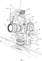
- Figure 1 shows photographic equipment arranged to perform various functions.
- the equipment includes a camera 10; a track 12 on which is mounted a first motion pancake 14 arranged to control lateral movement of the camera 10, a second motion pancake 16 mounted atop the first motion pancake 14 and arranged to control pan of the camera 10 from left to right; an L-shaped first bracket 18 mounted atop the second motion pancake 16; a third motion pancake 20 mounted to the first bracket 18 and arranged to control tilt of the camera 10 up and down; an L-shaped second bracket 22 mounted to the third motion pancake 20 and arranged to support the camera 10; and a superstructure 24 mounted to the second bracket 22 and arranged to support a control unit 26 and a FIZ support arm 28.
- a first motor 30 is mounted to the first motion pancake 14 and connected by a first control cable 32 to the control unit 26.
- a second motor 34 is mounted to the second motion pancake 16 and connected by a second control cable 36 to the control unit 26.
- a third motor 38 is mounted to the third motion pancake 20 and connected by a third control cable 40 to the control unit 26.
- a fourth motor 42 is mounted to the FIZ support arm 28 by means of a clamp 44, and is connected by a fourth control cable 46 to the control unit 26.
- first, second, third and fourth motors 30, 34, 38, 42 are similar.
- the motors will be described with reference to the first motor 30 shown in Figures 2 to 4 , but it will be understood that the description applies equally to all four motors shown in Figure 1 .
- the motor 30 has four primary elements: a housing 50, a coupling member 52, a drive shaft 54 and a toothed driving wheel 56.
- the housing 50 includes a body portion 58 which is generally rectangular-prismatic in shape, having an elongate rectangular mounting surface 60 along one side.
- the housing 50 has an extension portion 62 at one end of the body portion 58, extending away from the body portion 58 at an incline.
- the drive shaft 54 extends through the extension portion 62, in a direction transverse to the elongate direction.
- the arrangement is such that the drive shaft locates along an axis which is close to co-planar with the mounting surface 60.
- the drive shaft 54 terminates in a removable gear holding flange 64 on one transverse side of the extension portion 62.
- the gear holding flange 64 is arranged to clamp the toothed driving wheel 56 in position on the drive shaft 54, such that the toothed driving wheel 56 is arranged to turn with the drive shaft 54. It will be appreciated that the toothed driving wheel 56 can thus be readily exchanged for other driving wheels having different tooth numbers, and thus providing different gear ratios.
- the coupling member 52 is elongate, with a base 70, two side walls 72 which extend in the elongate direction and are perpendicular to the base 70, and two top flanges 74 which are parallel to and spaced from the base 70.
- An elongate gap 76 passes between the two top flanges 74.
- the coupling member 52 thus forms a T-shaped channel 78.
- the coupling member 52 is arranged to locate with its base 70 along the mounting surface 60 of the housing 50.
- the coupling member has a first end 80 arranged to locate towards the extension portion 62, and a second end 82 arranged to locate away from the extension portion 62.
- the side walls 72 are tapered at either end of the coupling member 52. At the first end 80, the side walls 72 are angled relative to the base 70 such that a leading edge of the side walls 72 is angled at about 30° relative to the base 70. At the second end 82, the side walls 72 are angled relative to the base 70 such that a trailing edge of the side walls 72 is angled at about 60° relative to the base 70.
- the coupling member 52 is fixed to the mounting surface 60 by two screws 84 located in the base 70 close to the first end 80.
- the coupling member 52 is arranged to flex to a degree about the screws 84. It will be appreciated that the tapered nature of the side walls 72 means that the rigidity of the coupling member 52 is reduced near the first end 80. The lack of fixing of the second end 82 of the coupling member 52 to the mounting surface 60 means that the coupling member is able to bend slightly about the screws 84 as will be discussed below.
- the motion pancakes 14, 16, 20 and the clamp 44 each have an engagement portion 100 along an edge thereof.
- the engagement portion 100 is elongate, with a length about half that of the coupling member 52.
- the engagement portion 100 is generally T-shaped in cross section, with a web 102 extending from a body of the respective motion pancake or clamp, and a flange 104 extending on either side of an outer edge of the web 102.
- a cam portion 106 is located along the flange 104.
- the cam portion 106 is moveable between a release position as shown in Figure 5 , in which the cam portion 106 is generally within the flange 104, and an engaged position where the cam portion 106 is misaligned with the flange 104.
- the arrangement is such that the engagement portion 100 is arranged to locate within the channel 78 formed by the coupling member 52 of the motor 30.
- the engagement portion 100 can readily move along the channel 78, with the web 102 locating within the gap 76, and the flange 104 sliding between the base 70 and the top flanges 74 of the coupling member 52.
- the cam portion 106 When the cam portion 106 is in its engaged position, it forces the flange 104 to bear against the base 70, and the cam portion 106 to bear against the top flanges 74. This provides sufficient friction to fix the engagement portion 100 in a desired longitudinal position along the coupling member 52.
- Figures 3 and 4 show the connection of the first motor 30 to the first motion pancake 14.
- the motion pancake 14 has a lever arm 108 connected to its cam portion 106, such that pivoting of the lever arm 108 causes the cam portion 106 to move between a released position as shown in Figure 3 and an engaged position.
- the motion pancake 14 has a toothed driven wheel 110.
- the engagement portion 100 of the motion pancake 14 is introduced into the coupling member 52 of the motor 30 at the second end 82 thereof. It is then slid along the coupling member 52 until the toothed driven wheel 110 engages and meshes with the toothed driving wheel 56. The application of a further pushing force to the engagement portion 100 acts to flex the coupling member 52, thus preloading the connection between the driving wheel 56 and the driven wheel 110. Activation of the lever arm 108 to move the cam portion 106 into the engaged position acts to lock the driving wheel 56 and driven wheel 110 in meshed engagement. Operation of the first motor 30 (by means of electrical current passed through the first control cable 32) thus causes rotation of driven wheel 110 of the first motion pancake 14, causing movement of the camera 10 and its associated framework along the track 12.
- the second motor 34 is coupled to the second motion pancake 16 in a similar way. Operation of the second motor 34 (by means of electrical current passed through the second control cable 36) causes rotation of a driven wheel of the second motion pancake 16, causing panning of the camera 10 about a vertical axis.
- the third motor 38 is coupled to the third motion pancake 20 in a similar way. Operation of the third motor 38 (by means of electrical current passed through the third control cable 40) causes rotation of a driven wheel of the third motion pancake 20, causing tilting of the camera 10 about a horizontal axis.
- the second motion pancake 14 and the third motion pancake 20 includes a mechanical rotation limiter (not shown).
- the rotation limiter provides a mechanical means for preventing over rotation of the respective motion pancake 14, 20. It also provides predetermined limits of rotation which provides a means for calibration of the system.
- the fourth motor 42 is held in position against the lens control driven wheels of the camera 10. Operation of the fourth motor 42 (by means of electrical current passed through the fourth control cable 46) causes rotation of the lens controls of the camera 10, allowing FIZ operation.
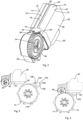
- the fourth motor 42 is held in position by means of a clamp 44, as shown in Figures 5 to 7 .
- the clamp 44 has a generally cylindrical aperture 120, formed by a fixed lower portion 122 which is connected to a movable upper portion 124 by means of a hinge connection 126.
- the aperture 120 includes suitably sized inserts 128 which act to define the diameter of the aperture 120.
- the upper portion 124 has a U-shaped flange 130 at an outer end, away from the hinge connection 126.
- the orientation is such that when the clamp is in a closed position the flange 130 sits along an upper mating surface 132 of the lower portion 122.
- the clamp 44 has an engagement portion 100 located beneath the lower portion 122, such that the flange 104 is parallel to the upper mating surface 132.
- An operating arm 133 is formed from two components: a threaded shaft 134 which is fixed to the cam portion 106, and an internally threaded sleeve 136 which is fixed to a handle 138.
- the shaft 134 has a diameter sufficiently small to locate within the U-shape of the flange 130.
- the sleeve 136 has a diameter sufficiently large to be unable to enter the U-shape of the flange 130.
- the operating arm 133 can be moved between three positions. In a first position, as shown in Figures 5 and 6 , the clamp 44 is closed, with the sleeve 136 locating over the flange 130 and holding the clamp in the closed position.
- the effective length of the operating arm 133 is such that when the sleeve 136 bears against the flange 130 the cam portion 106 is maintained in a release position relative to the engagement portion 100.
- Rotation of the sleeve 136 about its longitudinal axis causes shortening of the effective length of the operating arm 133.
- This action brings the operating arm into a second position, in which the sleeve 136 bears against the flange 130 and the cam portion 106 is maintained in an engaged position.
- the second position thus both locks the clamp 44 in a closed position, and also locks the engagement portion in a desired position (for instance, relative to the fourth motor 42). This is the state shown in Figure 1 .
- the operating arm 133 can also be pivoted about the cam portion 106 into a third position, in which the sleeve 136 is located outside the flange 130 as shown in Figure 7 . In this position the upper portion 124 is free to rotate about the hinge connection 126, thus opening the clamp 44.
- Attachment of the first bracket 18 to the second motion pancake 16 and the second bracket 22 to the third motion pancake 20 is by means of a clamp 150 as seen in Figure 8 .
- the clamp 150 has a base portion 152 and an upper portion 154.
- the base portion 152 is associated with curved bearing members 156, one located at a first end 158 of the clamp 150 and the other located at a second end 160 of the clamp 150.
- a thumb screw 162 passes through the upper portion 154 and the base portion 152 at the first end 158, and locates within a threaded apertures in the bearing member 156 of the first end 158.
- the thumb screw 162 acts to maintain the upper portion 154 and base portion 152 in relation to each other, while permitting limited relative rotation about the bearing member 156.
- a spring (not shown) is located between the upper portion 153 and the bas portion 152 around a shank of the thumb screw 162, allowing for preloading of the clamp 150.
- a lever arm 164 is associated with an adjustment pin 166.
- the adjustment pin 166 has an outer end receiving within the bearing member 156 of the second end 160. The arrangement is such that the application of a downward force to the lever arm 164 acts to raise the head of the adjustment pin 166, thus locking the upper portion 154 against the base portion 152. The application of an upward force to the lever arm 164 acts to lower the head of the adjustment pin 166, thus allowing a space to form between the upper portion 154 and the base portion 152.
Landscapes
- Engineering & Computer Science (AREA)
- General Engineering & Computer Science (AREA)
- Mechanical Engineering (AREA)
- Physics & Mathematics (AREA)
- General Physics & Mathematics (AREA)
- Power Engineering (AREA)
- Accessories Of Cameras (AREA)
- Lens Barrels (AREA)
- Connection Of Plates (AREA)
- Motor Or Generator Frames (AREA)
- Clamps And Clips (AREA)
Claims (9)
- Ein Motor (30) für photographisches Equipment, wobei der Motor (30) ein Gehäuse (50) mit einer länglichen Ausrichtung, eine Antriebswelle (54) und ein Kupplungselement (52) umfasst, wobei sich die Antriebswelle (54) durch einen Verlängerungsabschnitt (62) des Gehäuses (50) in einer Richtung quer zu der länglichen Ausrichtung erstreckt, wobei ein gezahntes Antriebsrad (56) auf der Antriebswelle (54) montiert ist; wobei das Kupplungselement (52) allgemein länglich ist und so angeordnet ist, dass es entlang einer länglichen Oberfläche (60) des Gehäuses (50) lokalisiert ist, wobei das Kupplungselement (52) so angeordnet ist, dass es sich entlang seiner Länge biegt, dadurch gekennzeichnet, dass der Motor (30) so angeordnet ist, dass er mit einer Komponente des photographischen Equipments koppelt, die eine angetriebene Komponente (14, 16, 20) ist, wobei das gezahnte Antriebsrad (56) so angeordnet ist, dass es mit einem Antriebszahnrad (110) der angetriebenen Komponente (14, 16, 20) ineinandergreift, wobei das Aufbringen einer Schubkraft auf die angetriebene Komponente (14, 16, 20) bewirkt, dass sich das Kupplungselement (52) biegt, wodurch die Verbindung zwischen dem gezahnten Antriebsrad (56) und dem Antriebszahnrad (110) vorgespannt wird.
- Ein Motor (30) für photographisches Equipment nach Anspruch 1, wobei das Kupplungselement (52) am Gehäuse (50) an einem ersten länglichen Ende (80) des Kupplungselements (52) befestigt ist und ein zweites längliches Ende (82) des Kupplungselements (52) relativ zum Gehäuse (50) beweglich ist.
- Ein Motor (30) für photographisches Equipment nach Anspruch 1 oder 2, wobei das Kupplungselement (52) einen Kanal (78) aufweist, der in der länglichen Richtung ausgerichtet ist.
- Ein Motor (30) für photographisches Equipment nach Anspruch 3, wobei der Kanal (78) an beiden länglichen Enden offen ist.
- Ein Motor (30) für photographisches Equipment nach Anspruch 3 oder 4, wobei der Kanal (78) eine teilweise offene Oberfläche (76) aufweist, die dem Gehäuse (50) abgewandt ist.
- Ein Motor (30) für photographisches Equipment nach einem der Ansprüche 3 bis 5, wenn abhängig von Anspruch 2, wobei der Kanal (78) Seitenwände (72) aufweist, die sich zum ersten länglichen Ende (80) des Kupplungselements (52) hin verjüngen.
- Ein Motor (30) für photographisches Equipment nach einem der vorhergehenden Ansprüche, wobei der Motor (30) so angeordnet ist, dass er die angetriebene Komponente (14, 16, 20) antreibt, und wobei das Kupplungselement (52) in seiner Form komplementär zu einem Eingriffsabschnitt der angetriebenen Komponente (14, 16, 20) ist.
- Ein Kupplungssystem für die Verbindung einer photographischen Equipment-Komponente (14, 16, 20) mit einem Motor (30), wobei das Kupplungssystem ein Kupplungselement (52) mit einem Kanal (78), das am Motor (30) oder der Komponente (14, 16, 20) befestigt ist, und einen Eingriffsabschnitt (100), der am entsprechend anderen, dem Motor (30) oder der Komponente (14, 16, 20) befestigt ist, umfasst, wobei der Eingriffsabschnitt (100) in seiner Form komplementär zu dem Kanal (78) ist, wobei der Eingriffsabschnitt (100) zwischen einer ersten Konfiguration, in der er leicht innerhalb des Kanals (78) bewegt werden kann, und einer zweiten Konfiguration, in der er in der Bewegung innerhalb des Kanals (78) eingeschränkt ist, beweglich ist, wobei der Motor (30) ein gezahntes Antriebsrad (56) aufweist und die Komponente (14, 16 20) ein Antriebszahnrad (110) aufweist, dadurch gekennzeichnet, dass das Kupplungselement (52) allgemein länglich ist und angeordnet ist, um sich entlang seiner Länge zu biegen, wobei das Aufbringen einer Schubkraft auf die angetriebene Komponente (14, 16, 20) bewirkt, dass das Kupplungselement (52) gebogen wird, wodurch die Verbindung zwischen dem gezahnten Antriebsrad (56) und dem Antriebszahnrad (110) vorgespannt wird.
- Ein Kupplungssystem nach Anspruch 8, wobei der Eingriffsabschnitt (100) einen Nockenabschnitt (106) aufweist, wobei der Nockenabschnitt (106) zwischen einer ersten Position, in der der Nockenabschnitt (106) im Allgemeinen mit dem Rest des Eingriffsabschnitts (100) ausgerichtet ist, und einer zweiten Position, in der der Nockenabschnitt (106) nicht mit dem Rest des Eingriffsabschnitts (100) ausgerichtet ist, beweglich ist.
Applications Claiming Priority (2)
| Application Number | Priority Date | Filing Date | Title |
|---|---|---|---|
| AU2016905275A AU2016905275A0 (en) | 2016-12-20 | Camera control methods and apparatus | |
| PCT/AU2017/051414 WO2018112521A1 (en) | 2016-12-20 | 2017-12-19 | Camera control methods and apparatus |
Publications (3)
| Publication Number | Publication Date |
|---|---|
| EP3559536A1 EP3559536A1 (de) | 2019-10-30 |
| EP3559536A4 EP3559536A4 (de) | 2020-12-09 |
| EP3559536B1 true EP3559536B1 (de) | 2023-06-28 |
Family
ID=62624384
Family Applications (1)
| Application Number | Title | Priority Date | Filing Date |
|---|---|---|---|
| EP17883468.5A Active EP3559536B1 (de) | 2016-12-20 | 2017-12-19 | Kamerasteuerungsverfahren und vorrichtung |
Country Status (7)
| Country | Link |
|---|---|
| US (1) | US11137668B2 (de) |
| EP (1) | EP3559536B1 (de) |
| JP (1) | JP7328896B2 (de) |
| CN (1) | CN110100132A (de) |
| AU (1) | AU2017381400B2 (de) |
| CA (1) | CA3047799A1 (de) |
| WO (1) | WO2018112521A1 (de) |
Families Citing this family (7)
| Publication number | Priority date | Publication date | Assignee | Title |
|---|---|---|---|---|
| EP3410692A4 (de) * | 2016-03-31 | 2019-02-20 | Ninebot (Beijing) Tech Co., Ltd. | Sich auf dem boden bewegende vorrichtung, stabilisator, halterung und roboterkopf |
| JP2020071395A (ja) * | 2018-10-31 | 2020-05-07 | キヤノン株式会社 | 雲台システム |
| US11181812B2 (en) * | 2018-10-31 | 2021-11-23 | Canon Kabushiki Kaisha | Camera platform system |
| US11487187B2 (en) * | 2019-12-11 | 2022-11-01 | Tilta Inc. | Camera lens support system |
| FR3107754B1 (fr) * | 2020-02-27 | 2022-03-18 | Xyzed | Lyre motorisée pour vidéo projecteur |
| CN113253541B (zh) * | 2021-06-11 | 2022-03-18 | 邯郸学院 | 一种定格动画拍摄装置 |
| CN116061832B (zh) * | 2022-12-29 | 2025-07-18 | 深圳市乐其创新股份有限公司 | 挂置式车拍装置 |
Family Cites Families (15)
| Publication number | Priority date | Publication date | Assignee | Title |
|---|---|---|---|---|
| US4525052A (en) | 1983-01-27 | 1985-06-25 | Slik Tripod Co., Ltd. | Device for fixing a camera to a tripod |
| US5230490A (en) | 1992-10-26 | 1993-07-27 | Saunders Photo/Graphic Inc. | Quick release camera mounting mechanism |
| JPH1068995A (ja) * | 1996-08-26 | 1998-03-10 | Hitachi Denshi Ltd | ウォーム歯車バックラッシュ除去機構 |
| JP4343458B2 (ja) | 2001-05-22 | 2009-10-14 | 池上通信機株式会社 | 撮像装置 |
| US7077582B2 (en) * | 2003-08-20 | 2006-07-18 | Johnson Joseph M | Quick-release clamp for photographic equipment |
| US8393104B1 (en) * | 2003-12-02 | 2013-03-12 | Grip Pod Systems International, Llc | Folding stack improvements |
| DE102004015947A1 (de) * | 2004-03-25 | 2005-10-13 | Arnold & Richter Cine Technik Gmbh & Co Betriebs Kg | Verfahren und Vorrichtung zum Einstellen der Bildschärfe am Kameraobjektiv einer Laufbildkamera |
| CN100470354C (zh) * | 2005-08-15 | 2009-03-18 | 潘国平 | 360度全角控制的无电刷球型摄像机云台 |
| US8087315B2 (en) | 2006-10-10 | 2012-01-03 | Honeywell International Inc. | Methods and systems for attaching and detaching a payload device to and from, respectively, a gimbal system without requiring use of a mechanical tool |
| JP5060228B2 (ja) * | 2007-09-20 | 2012-10-31 | 日本電産セイミツ株式会社 | 振動モータ |
| GB2470774B (en) * | 2009-06-05 | 2012-10-10 | Ronford Baker Engineering Company Ltd | Support |
| CN204805716U (zh) * | 2015-04-15 | 2015-11-25 | 深圳市大疆创新科技有限公司 | 夹紧机构及应用该夹紧机构的飞行器 |
| CN204886552U (zh) * | 2015-08-28 | 2015-12-16 | 东莞市万鑫机电有限公司 | 一种新型减速电机 |
| CN204986276U (zh) * | 2015-09-16 | 2016-01-20 | 中山大山摄影器材有限公司 | 一种无线控制的多轴旋转摄影云台 |
| CN205690019U (zh) * | 2016-06-15 | 2016-11-16 | 宁波意美捷影视设备有限公司 | 三轴电动云台 |
-
2017
- 2017-12-19 AU AU2017381400A patent/AU2017381400B2/en active Active
- 2017-12-19 JP JP2019553602A patent/JP7328896B2/ja active Active
- 2017-12-19 US US16/473,176 patent/US11137668B2/en active Active
- 2017-12-19 EP EP17883468.5A patent/EP3559536B1/de active Active
- 2017-12-19 CN CN201780078705.7A patent/CN110100132A/zh active Pending
- 2017-12-19 WO PCT/AU2017/051414 patent/WO2018112521A1/en not_active Ceased
- 2017-12-19 CA CA3047799A patent/CA3047799A1/en active Pending
Also Published As
| Publication number | Publication date |
|---|---|
| AU2017381400B2 (en) | 2024-02-29 |
| CA3047799A1 (en) | 2018-06-28 |
| JP7328896B2 (ja) | 2023-08-17 |
| AU2017381400A1 (en) | 2019-08-08 |
| EP3559536A4 (de) | 2020-12-09 |
| CN110100132A (zh) | 2019-08-06 |
| JP2020514836A (ja) | 2020-05-21 |
| WO2018112521A1 (en) | 2018-06-28 |
| US20190324353A1 (en) | 2019-10-24 |
| US11137668B2 (en) | 2021-10-05 |
| EP3559536A1 (de) | 2019-10-30 |
Similar Documents
| Publication | Publication Date | Title |
|---|---|---|
| EP3559536B1 (de) | Kamerasteuerungsverfahren und vorrichtung | |
| EP3396225B1 (de) | Stützmechanismus, einstellungsvorrichtung und schwenk-neige-kopf dafür | |
| US10428998B2 (en) | Gimbal structure and gear adjusting mechanism thereof | |
| JP7097184B2 (ja) | 表示画面の取り付け具の改良 | |
| US6966657B2 (en) | Projection lens fixation and adjustment mechanism | |
| CN104885447B (zh) | 具有微调结构的短焦投影机支架 | |
| CN107002938B (zh) | 云台轴臂结构及具有该云台轴臂结构的云台结构 | |
| EP2963330A1 (de) | Überwachungsvorrichtung und Verfahren zur Einstellung einer festen Überwachungsvorrichtung | |
| JP2018519548A (ja) | 位置規制装置、およびこの位置規制装置を有する無人航空機 | |
| CN107278247B (zh) | 手持云台、拍摄设备及其连接座以及定位结构 | |
| US9182106B2 (en) | Device for adjusting an optical tube arranged in the housing of a headlight or optical device | |
| HK40015178A (en) | Camera control methods and apparatus | |
| HK40015178B (en) | Camera control methods and apparatus | |
| EP3967917A1 (de) | Elektronisch gesteuerte schiebevorrichtung für eine fotografische vorrichtung und verriegelungsanordnung dafür | |
| CN114833855A (zh) | 一种可变角度的管件夹持装置及管件夹持方法 | |
| JP2012118146A (ja) | 撮像装置支持機構 | |
| CN113701004A (zh) | 摄影设备支撑装置 | |
| CN217153535U (zh) | 调平装置、手持云台、拍摄设备及可移动平台 | |
| EP2799921A1 (de) | Einstellungsvorrichtung für ein Kameramodul | |
| CN216896544U (zh) | 一种云台锁定机构 | |
| DE202023107525U1 (de) | Horizontstabilisierter Kameraträger | |
| JP5809107B2 (ja) | ドーム型カメラ調整システム、ドーム型カメラ、及び調整装置 | |
| JP2025174227A (ja) | 姿勢調整機構及び画像処理システム | |
| CN119826064A (zh) | 摄像头结构 | |
| CN206147237U (zh) | 跟焦器固定架 |
Legal Events
| Date | Code | Title | Description |
|---|---|---|---|
| STAA | Information on the status of an ep patent application or granted ep patent |
Free format text: STATUS: THE INTERNATIONAL PUBLICATION HAS BEEN MADE |
|
| PUAI | Public reference made under article 153(3) epc to a published international application that has entered the european phase |
Free format text: ORIGINAL CODE: 0009012 |
|
| STAA | Information on the status of an ep patent application or granted ep patent |
Free format text: STATUS: REQUEST FOR EXAMINATION WAS MADE |
|
| 17P | Request for examination filed |
Effective date: 20190718 |
|
| AK | Designated contracting states |
Kind code of ref document: A1 Designated state(s): AL AT BE BG CH CY CZ DE DK EE ES FI FR GB GR HR HU IE IS IT LI LT LU LV MC MK MT NL NO PL PT RO RS SE SI SK SM TR |
|
| AX | Request for extension of the european patent |
Extension state: BA ME |
|
| DAV | Request for validation of the european patent (deleted) | ||
| DAX | Request for extension of the european patent (deleted) | ||
| REG | Reference to a national code |
Ref country code: HK Ref legal event code: DE Ref document number: 40015178 Country of ref document: HK |
|
| RIC1 | Information provided on ipc code assigned before grant |
Ipc: H02N 11/00 20060101ALI20200730BHEP Ipc: B60R 11/04 20060101ALI20200730BHEP Ipc: F16M 13/00 20060101ALI20200730BHEP Ipc: H02K 5/00 20060101ALI20200730BHEP Ipc: F16M 11/00 20060101ALI20200730BHEP Ipc: G03B 17/56 20060101AFI20200730BHEP |
|
| REG | Reference to a national code |
Ref country code: DE Ref legal event code: R079 Free format text: PREVIOUS MAIN CLASS: F16M0011000000 Ipc: G03B0017560000 Ref document number: 602017070811 Country of ref document: DE |
|
| A4 | Supplementary search report drawn up and despatched |
Effective date: 20201109 |
|
| RIC1 | Information provided on ipc code assigned before grant |
Ipc: G03B 17/56 20060101AFI20201103BHEP Ipc: F16M 13/00 20060101ALI20201103BHEP Ipc: B60R 11/04 20060101ALI20201103BHEP Ipc: F16M 11/00 20060101ALI20201103BHEP Ipc: H02N 11/00 20060101ALI20201103BHEP Ipc: H02K 5/00 20060101ALI20201103BHEP |
|
| RIN1 | Information on inventor provided before grant (corrected) |
Inventor name: LIWSZYC, ADAM |
|
| GRAP | Despatch of communication of intention to grant a patent |
Free format text: ORIGINAL CODE: EPIDOSNIGR1 |
|
| STAA | Information on the status of an ep patent application or granted ep patent |
Free format text: STATUS: GRANT OF PATENT IS INTENDED |
|
| INTG | Intention to grant announced |
Effective date: 20230127 |
|
| GRAS | Grant fee paid |
Free format text: ORIGINAL CODE: EPIDOSNIGR3 |
|
| GRAA | (expected) grant |
Free format text: ORIGINAL CODE: 0009210 |
|
| STAA | Information on the status of an ep patent application or granted ep patent |
Free format text: STATUS: THE PATENT HAS BEEN GRANTED |
|
| AK | Designated contracting states |
Kind code of ref document: B1 Designated state(s): AL AT BE BG CH CY CZ DE DK EE ES FI FR GB GR HR HU IE IS IT LI LT LU LV MC MK MT NL NO PL PT RO RS SE SI SK SM TR |
|
| REG | Reference to a national code |
Ref country code: CH Ref legal event code: EP |
|
| REG | Reference to a national code |
Ref country code: AT Ref legal event code: REF Ref document number: 1583232 Country of ref document: AT Kind code of ref document: T Effective date: 20230715 |
|
| REG | Reference to a national code |
Ref country code: IE Ref legal event code: FG4D |
|
| REG | Reference to a national code |
Ref country code: DE Ref legal event code: R096 Ref document number: 602017070811 Country of ref document: DE |
|
| REG | Reference to a national code |
Ref country code: LT Ref legal event code: MG9D |
|
| PG25 | Lapsed in a contracting state [announced via postgrant information from national office to epo] |
Ref country code: SE Free format text: LAPSE BECAUSE OF FAILURE TO SUBMIT A TRANSLATION OF THE DESCRIPTION OR TO PAY THE FEE WITHIN THE PRESCRIBED TIME-LIMIT Effective date: 20230628 Ref country code: NO Free format text: LAPSE BECAUSE OF FAILURE TO SUBMIT A TRANSLATION OF THE DESCRIPTION OR TO PAY THE FEE WITHIN THE PRESCRIBED TIME-LIMIT Effective date: 20230928 |
|
| REG | Reference to a national code |
Ref country code: NL Ref legal event code: MP Effective date: 20230628 |
|
| U01 | Request for unitary effect filed |
Effective date: 20230927 |
|
| REG | Reference to a national code |
Ref country code: AT Ref legal event code: MK05 Ref document number: 1583232 Country of ref document: AT Kind code of ref document: T Effective date: 20230628 |
|
| U50 | Request for re-establishment of rights filed [unitary effect] |
Free format text: RE-ESTABLISHMENT OF RIGHTS REQUESTED DUE TO A LATE FILING ON THE REQUEST FOR UNITARY EFFECT Effective date: 20230927 |
|
| PG25 | Lapsed in a contracting state [announced via postgrant information from national office to epo] |
Ref country code: RS Free format text: LAPSE BECAUSE OF FAILURE TO SUBMIT A TRANSLATION OF THE DESCRIPTION OR TO PAY THE FEE WITHIN THE PRESCRIBED TIME-LIMIT Effective date: 20230628 Ref country code: NL Free format text: LAPSE BECAUSE OF FAILURE TO SUBMIT A TRANSLATION OF THE DESCRIPTION OR TO PAY THE FEE WITHIN THE PRESCRIBED TIME-LIMIT Effective date: 20230628 Ref country code: LV Free format text: LAPSE BECAUSE OF FAILURE TO SUBMIT A TRANSLATION OF THE DESCRIPTION OR TO PAY THE FEE WITHIN THE PRESCRIBED TIME-LIMIT Effective date: 20230628 Ref country code: LT Free format text: LAPSE BECAUSE OF FAILURE TO SUBMIT A TRANSLATION OF THE DESCRIPTION OR TO PAY THE FEE WITHIN THE PRESCRIBED TIME-LIMIT Effective date: 20230628 Ref country code: HR Free format text: LAPSE BECAUSE OF FAILURE TO SUBMIT A TRANSLATION OF THE DESCRIPTION OR TO PAY THE FEE WITHIN THE PRESCRIBED TIME-LIMIT Effective date: 20230628 Ref country code: GR Free format text: LAPSE BECAUSE OF FAILURE TO SUBMIT A TRANSLATION OF THE DESCRIPTION OR TO PAY THE FEE WITHIN THE PRESCRIBED TIME-LIMIT Effective date: 20230929 |
|
| PG25 | Lapsed in a contracting state [announced via postgrant information from national office to epo] |
Ref country code: FI Free format text: LAPSE BECAUSE OF FAILURE TO SUBMIT A TRANSLATION OF THE DESCRIPTION OR TO PAY THE FEE WITHIN THE PRESCRIBED TIME-LIMIT Effective date: 20230628 |
|
| PG25 | Lapsed in a contracting state [announced via postgrant information from national office to epo] |
Ref country code: SK Free format text: LAPSE BECAUSE OF FAILURE TO SUBMIT A TRANSLATION OF THE DESCRIPTION OR TO PAY THE FEE WITHIN THE PRESCRIBED TIME-LIMIT Effective date: 20230628 |
|
| PG25 | Lapsed in a contracting state [announced via postgrant information from national office to epo] |
Ref country code: ES Free format text: LAPSE BECAUSE OF FAILURE TO SUBMIT A TRANSLATION OF THE DESCRIPTION OR TO PAY THE FEE WITHIN THE PRESCRIBED TIME-LIMIT Effective date: 20230628 |
|
| PG25 | Lapsed in a contracting state [announced via postgrant information from national office to epo] |
Ref country code: IS Free format text: LAPSE BECAUSE OF FAILURE TO SUBMIT A TRANSLATION OF THE DESCRIPTION OR TO PAY THE FEE WITHIN THE PRESCRIBED TIME-LIMIT Effective date: 20231028 |
|
| PG25 | Lapsed in a contracting state [announced via postgrant information from national office to epo] |
Ref country code: SM Free format text: LAPSE BECAUSE OF FAILURE TO SUBMIT A TRANSLATION OF THE DESCRIPTION OR TO PAY THE FEE WITHIN THE PRESCRIBED TIME-LIMIT Effective date: 20230628 Ref country code: SK Free format text: LAPSE BECAUSE OF FAILURE TO SUBMIT A TRANSLATION OF THE DESCRIPTION OR TO PAY THE FEE WITHIN THE PRESCRIBED TIME-LIMIT Effective date: 20230628 Ref country code: RO Free format text: LAPSE BECAUSE OF FAILURE TO SUBMIT A TRANSLATION OF THE DESCRIPTION OR TO PAY THE FEE WITHIN THE PRESCRIBED TIME-LIMIT Effective date: 20230628 Ref country code: PT Free format text: LAPSE BECAUSE OF FAILURE TO SUBMIT A TRANSLATION OF THE DESCRIPTION OR TO PAY THE FEE WITHIN THE PRESCRIBED TIME-LIMIT Effective date: 20231030 Ref country code: IS Free format text: LAPSE BECAUSE OF FAILURE TO SUBMIT A TRANSLATION OF THE DESCRIPTION OR TO PAY THE FEE WITHIN THE PRESCRIBED TIME-LIMIT Effective date: 20231028 Ref country code: ES Free format text: LAPSE BECAUSE OF FAILURE TO SUBMIT A TRANSLATION OF THE DESCRIPTION OR TO PAY THE FEE WITHIN THE PRESCRIBED TIME-LIMIT Effective date: 20230628 Ref country code: EE Free format text: LAPSE BECAUSE OF FAILURE TO SUBMIT A TRANSLATION OF THE DESCRIPTION OR TO PAY THE FEE WITHIN THE PRESCRIBED TIME-LIMIT Effective date: 20230628 Ref country code: CZ Free format text: LAPSE BECAUSE OF FAILURE TO SUBMIT A TRANSLATION OF THE DESCRIPTION OR TO PAY THE FEE WITHIN THE PRESCRIBED TIME-LIMIT Effective date: 20230628 Ref country code: AT Free format text: LAPSE BECAUSE OF FAILURE TO SUBMIT A TRANSLATION OF THE DESCRIPTION OR TO PAY THE FEE WITHIN THE PRESCRIBED TIME-LIMIT Effective date: 20230628 |
|
| PG25 | Lapsed in a contracting state [announced via postgrant information from national office to epo] |
Ref country code: PL Free format text: LAPSE BECAUSE OF FAILURE TO SUBMIT A TRANSLATION OF THE DESCRIPTION OR TO PAY THE FEE WITHIN THE PRESCRIBED TIME-LIMIT Effective date: 20230628 |
|
| REG | Reference to a national code |
Ref country code: DE Ref legal event code: R097 Ref document number: 602017070811 Country of ref document: DE |
|
| PLBE | No opposition filed within time limit |
Free format text: ORIGINAL CODE: 0009261 |
|
| STAA | Information on the status of an ep patent application or granted ep patent |
Free format text: STATUS: NO OPPOSITION FILED WITHIN TIME LIMIT |
|
| PG25 | Lapsed in a contracting state [announced via postgrant information from national office to epo] |
Ref country code: IT Free format text: LAPSE BECAUSE OF FAILURE TO SUBMIT A TRANSLATION OF THE DESCRIPTION OR TO PAY THE FEE WITHIN THE PRESCRIBED TIME-LIMIT Effective date: 20230628 |
|
| 26N | No opposition filed |
Effective date: 20240402 |
|
| U52 | Request for re-establishment of rights deleted [unitary effect] |
Effective date: 20240619 |
|
| PG25 | Lapsed in a contracting state [announced via postgrant information from national office to epo] |
Ref country code: SI Free format text: LAPSE BECAUSE OF FAILURE TO SUBMIT A TRANSLATION OF THE DESCRIPTION OR TO PAY THE FEE WITHIN THE PRESCRIBED TIME-LIMIT Effective date: 20230628 |
|
| REG | Reference to a national code |
Ref country code: CH Ref legal event code: PL |
|
| PG25 | Lapsed in a contracting state [announced via postgrant information from national office to epo] |
Ref country code: LU Free format text: LAPSE BECAUSE OF NON-PAYMENT OF DUE FEES Effective date: 20231219 |
|
| PG25 | Lapsed in a contracting state [announced via postgrant information from national office to epo] |
Ref country code: MC Free format text: LAPSE BECAUSE OF FAILURE TO SUBMIT A TRANSLATION OF THE DESCRIPTION OR TO PAY THE FEE WITHIN THE PRESCRIBED TIME-LIMIT Effective date: 20230628 |
|
| REG | Reference to a national code |
Ref country code: BE Ref legal event code: MM Effective date: 20231231 |
|
| PG25 | Lapsed in a contracting state [announced via postgrant information from national office to epo] |
Ref country code: MC Free format text: LAPSE BECAUSE OF FAILURE TO SUBMIT A TRANSLATION OF THE DESCRIPTION OR TO PAY THE FEE WITHIN THE PRESCRIBED TIME-LIMIT Effective date: 20230628 Ref country code: LU Free format text: LAPSE BECAUSE OF NON-PAYMENT OF DUE FEES Effective date: 20231219 |
|
| U04 | Request for unitary effect rejected |
Effective date: 20240814 |
|
| REG | Reference to a national code |
Ref country code: IE Ref legal event code: MM4A |
|
| PG25 | Lapsed in a contracting state [announced via postgrant information from national office to epo] |
Ref country code: IE Free format text: LAPSE BECAUSE OF NON-PAYMENT OF DUE FEES Effective date: 20231219 |
|
| PG25 | Lapsed in a contracting state [announced via postgrant information from national office to epo] |
Ref country code: BE Free format text: LAPSE BECAUSE OF NON-PAYMENT OF DUE FEES Effective date: 20231231 |
|
| PG25 | Lapsed in a contracting state [announced via postgrant information from national office to epo] |
Ref country code: CH Free format text: LAPSE BECAUSE OF NON-PAYMENT OF DUE FEES Effective date: 20231231 |
|
| PG25 | Lapsed in a contracting state [announced via postgrant information from national office to epo] |
Ref country code: IE Free format text: LAPSE BECAUSE OF NON-PAYMENT OF DUE FEES Effective date: 20231219 Ref country code: CH Free format text: LAPSE BECAUSE OF NON-PAYMENT OF DUE FEES Effective date: 20231231 Ref country code: BE Free format text: LAPSE BECAUSE OF NON-PAYMENT OF DUE FEES Effective date: 20231231 |
|
| PG25 | Lapsed in a contracting state [announced via postgrant information from national office to epo] |
Ref country code: BG Free format text: LAPSE BECAUSE OF FAILURE TO SUBMIT A TRANSLATION OF THE DESCRIPTION OR TO PAY THE FEE WITHIN THE PRESCRIBED TIME-LIMIT Effective date: 20230628 |
|
| PG25 | Lapsed in a contracting state [announced via postgrant information from national office to epo] |
Ref country code: BG Free format text: LAPSE BECAUSE OF FAILURE TO SUBMIT A TRANSLATION OF THE DESCRIPTION OR TO PAY THE FEE WITHIN THE PRESCRIBED TIME-LIMIT Effective date: 20230628 |
|
| U52 | Request for re-establishment of rights deleted [unitary effect] |
Effective date: 20240619 |
|
| PG25 | Lapsed in a contracting state [announced via postgrant information from national office to epo] |
Ref country code: DK Free format text: LAPSE BECAUSE OF FAILURE TO SUBMIT A TRANSLATION OF THE DESCRIPTION OR TO PAY THE FEE WITHIN THE PRESCRIBED TIME-LIMIT Effective date: 20230628 |
|
| PG25 | Lapsed in a contracting state [announced via postgrant information from national office to epo] |
Ref country code: CY Free format text: LAPSE BECAUSE OF FAILURE TO SUBMIT A TRANSLATION OF THE DESCRIPTION OR TO PAY THE FEE WITHIN THE PRESCRIBED TIME-LIMIT; INVALID AB INITIO Effective date: 20171219 |
|
| PG25 | Lapsed in a contracting state [announced via postgrant information from national office to epo] |
Ref country code: HU Free format text: LAPSE BECAUSE OF FAILURE TO SUBMIT A TRANSLATION OF THE DESCRIPTION OR TO PAY THE FEE WITHIN THE PRESCRIBED TIME-LIMIT; INVALID AB INITIO Effective date: 20171219 |
|
| PG25 | Lapsed in a contracting state [announced via postgrant information from national office to epo] |
Ref country code: TR Free format text: LAPSE BECAUSE OF FAILURE TO SUBMIT A TRANSLATION OF THE DESCRIPTION OR TO PAY THE FEE WITHIN THE PRESCRIBED TIME-LIMIT Effective date: 20230628 |
|
| PGFP | Annual fee paid to national office [announced via postgrant information from national office to epo] |
Ref country code: GB Payment date: 20251215 Year of fee payment: 9 |
|
| PGFP | Annual fee paid to national office [announced via postgrant information from national office to epo] |
Ref country code: FR Payment date: 20251215 Year of fee payment: 9 |
|
| PGFP | Annual fee paid to national office [announced via postgrant information from national office to epo] |
Ref country code: DE Payment date: 20251230 Year of fee payment: 9 |