EP3559631B1 - Verfahren zum zählen von partikeln in einer probe durch linsenlose bildgebung - Google Patents
Verfahren zum zählen von partikeln in einer probe durch linsenlose bildgebung Download PDFInfo
- Publication number
- EP3559631B1 EP3559631B1 EP17829258.7A EP17829258A EP3559631B1 EP 3559631 B1 EP3559631 B1 EP 3559631B1 EP 17829258 A EP17829258 A EP 17829258A EP 3559631 B1 EP3559631 B1 EP 3559631B1
- Authority
- EP
- European Patent Office
- Prior art keywords
- interest
- image
- regions
- sample
- focusing
- Prior art date
- Legal status (The legal status is an assumption and is not a legal conclusion. Google has not performed a legal analysis and makes no representation as to the accuracy of the status listed.)
- Active
Links
Images


Classifications
-
- G—PHYSICS
- G01—MEASURING; TESTING
- G01N—INVESTIGATING OR ANALYSING MATERIALS BY DETERMINING THEIR CHEMICAL OR PHYSICAL PROPERTIES
- G01N15/00—Investigating characteristics of particles; Investigating permeability, pore-volume or surface-area of porous materials
- G01N15/10—Investigating individual particles
- G01N15/14—Optical investigation techniques, e.g. flow cytometry
- G01N15/1429—Signal processing
- G01N15/1433—Signal processing using image recognition
-
- G—PHYSICS
- G03—PHOTOGRAPHY; CINEMATOGRAPHY; ANALOGOUS TECHNIQUES USING WAVES OTHER THAN OPTICAL WAVES; ELECTROGRAPHY; HOLOGRAPHY
- G03H—HOLOGRAPHIC PROCESSES OR APPARATUS
- G03H1/00—Holographic processes or apparatus using light, infrared or ultraviolet waves for obtaining holograms or for obtaining an image from them; Details peculiar thereto
- G03H1/04—Processes or apparatus for producing holograms
- G03H1/0443—Digital holography, i.e. recording holograms with digital recording means
-
- G—PHYSICS
- G03—PHOTOGRAPHY; CINEMATOGRAPHY; ANALOGOUS TECHNIQUES USING WAVES OTHER THAN OPTICAL WAVES; ELECTROGRAPHY; HOLOGRAPHY
- G03H—HOLOGRAPHIC PROCESSES OR APPARATUS
- G03H1/00—Holographic processes or apparatus using light, infrared or ultraviolet waves for obtaining holograms or for obtaining an image from them; Details peculiar thereto
- G03H1/04—Processes or apparatus for producing holograms
- G03H1/08—Synthesising holograms, i.e. holograms synthesized from objects or objects from holograms
- G03H1/0866—Digital holographic imaging, i.e. synthesizing holobjects from holograms
-
- G—PHYSICS
- G06—COMPUTING OR CALCULATING; COUNTING
- G06V—IMAGE OR VIDEO RECOGNITION OR UNDERSTANDING
- G06V20/00—Scenes; Scene-specific elements
- G06V20/60—Type of objects
- G06V20/69—Microscopic objects, e.g. biological cells or cellular parts
- G06V20/695—Preprocessing, e.g. image segmentation
-
- G—PHYSICS
- G06—COMPUTING OR CALCULATING; COUNTING
- G06V—IMAGE OR VIDEO RECOGNITION OR UNDERSTANDING
- G06V20/00—Scenes; Scene-specific elements
- G06V20/60—Type of objects
- G06V20/69—Microscopic objects, e.g. biological cells or cellular parts
- G06V20/698—Matching; Classification
-
- G—PHYSICS
- G01—MEASURING; TESTING
- G01N—INVESTIGATING OR ANALYSING MATERIALS BY DETERMINING THEIR CHEMICAL OR PHYSICAL PROPERTIES
- G01N15/00—Investigating characteristics of particles; Investigating permeability, pore-volume or surface-area of porous materials
- G01N15/01—Investigating characteristics of particles; Investigating permeability, pore-volume or surface-area of porous materials specially adapted for biological cells, e.g. blood cells
- G01N2015/012—Red blood cells
-
- G—PHYSICS
- G01—MEASURING; TESTING
- G01N—INVESTIGATING OR ANALYSING MATERIALS BY DETERMINING THEIR CHEMICAL OR PHYSICAL PROPERTIES
- G01N15/00—Investigating characteristics of particles; Investigating permeability, pore-volume or surface-area of porous materials
- G01N15/01—Investigating characteristics of particles; Investigating permeability, pore-volume or surface-area of porous materials specially adapted for biological cells, e.g. blood cells
- G01N2015/016—White blood cells
-
- G—PHYSICS
- G01—MEASURING; TESTING
- G01N—INVESTIGATING OR ANALYSING MATERIALS BY DETERMINING THEIR CHEMICAL OR PHYSICAL PROPERTIES
- G01N15/00—Investigating characteristics of particles; Investigating permeability, pore-volume or surface-area of porous materials
- G01N15/10—Investigating individual particles
- G01N15/14—Optical investigation techniques, e.g. flow cytometry
- G01N15/1434—Optical arrangements
- G01N2015/1454—Optical arrangements using phase shift or interference, e.g. for improving contrast
-
- G—PHYSICS
- G01—MEASURING; TESTING
- G01N—INVESTIGATING OR ANALYSING MATERIALS BY DETERMINING THEIR CHEMICAL OR PHYSICAL PROPERTIES
- G01N15/00—Investigating characteristics of particles; Investigating permeability, pore-volume or surface-area of porous materials
- G01N15/10—Investigating individual particles
- G01N15/14—Optical investigation techniques, e.g. flow cytometry
- G01N2015/1486—Counting the particles
-
- G—PHYSICS
- G03—PHOTOGRAPHY; CINEMATOGRAPHY; ANALOGOUS TECHNIQUES USING WAVES OTHER THAN OPTICAL WAVES; ELECTROGRAPHY; HOLOGRAPHY
- G03H—HOLOGRAPHIC PROCESSES OR APPARATUS
- G03H1/00—Holographic processes or apparatus using light, infrared or ultraviolet waves for obtaining holograms or for obtaining an image from them; Details peculiar thereto
- G03H1/04—Processes or apparatus for producing holograms
- G03H1/0443—Digital holography, i.e. recording holograms with digital recording means
- G03H2001/0447—In-line recording arrangement
Definitions
- the invention is an optical method for counting particles, in particular blood cells, disposed in a sample using a lensless imaging device.
- the document WO2008090330 describes a device allowing the observation of samples comprising cells by lensless imaging.
- the sample is placed between a light source and an image sensor, without having an optical magnifying lens between the sample and the image sensor.
- the image sensor collects an image of a light wave transmitted by the sample.
- This image also called a hologram, is formed of interference figures between the light wave emitted by the light source and transmitted by the sample, and diffraction waves, resulting from the diffraction by the sample of the wave light emitted by the light source.
- These interference figures are generally formed by a succession of concentric rings. They are sometimes called diffraction figures, or designated by the English term "diffraction pattern".
- each cell can be associated with an interference figure; their enumeration allows the counting of cells present in the sample. But the hologram does not allow reliable cell counting as the concentration increases.
- the hologram acquired by the image sensor can be processed by a holographic reconstruction algorithm, so as to estimate optical properties of the sample, for example an absorption or a phase shift value of the light wave passing through the sample and propagating to the image sensor.
- This type of algorithm is well known in the field of holographic reconstruction.
- An example of a holographic reconstruction algorithm is described in the publication Ryle et al, “Digital in-line holography of biological specimens”, Proc. Of SPIE Vol. 6311 (2006 ).
- such algorithms can give rise to the appearance of a reconstruction noise, designated by the term “twin image”, on the reconstructed image. Their application therefore requires certain precautions.
- Requirement US2012 / 0218379 describes a method for reconstructing a complex image of a sample, the latter comprising amplitude and phase information.
- Requirement US2012 / 0148141 applies the process described in the application US2012 / 0218379 to reconstruct a complex image of sperm and to characterize their mobility.
- Lensless imaging has been applied in WO2016 / 151249 to analyze a sample containing cells.
- An alternative method of observing samples is holographic microscopy, for example described in US2013 / 0308135 , or, applied to blood particles, in WO2015 / 195642 , the latter describing in particular an estimate of the volume of red blood cells or white blood cells.
- the methods by holographic microscopy are relatively complex to implement.
- the document US2008 / 0160566 proposes a simple alternative, also aimed at determining the volume of white blood cells, by forming an image using a standard optical device, the white blood cells being previously labeled using a colored reagent.
- a common point of the methods exposed in the three preceding documents is a weak field of observation.
- the inventors wished to propose a simple and inexpensive alternative for counting particles of interest in a sample, by taking advantage of the large field of observation conferred by imaging without a lens.
- the invention may constitute an alternative to the hematology machines currently available for carrying out counts of cells in blood.
- the invention is particularly suitable for samples exhibiting high concentrations of particles, which can reach several hundreds of thousands of particles per microliter.
- the classification allows a more precise quantification of the particles of interest, compared to a simple count of the selected regions of interest.
- a morphological criterion can in particular be chosen from a diameter, a size or a form factor of each region of interest. Several morphological criteria can be combined.
- Step f) may include taking into account a reference size, and / or a reference shape, representative of a predetermined number of particles of interest; the classification is then carried out as a function of said reference size.
- the sample can be mixed with a spherization reagent prior to step b), to modify the shape of the particles of interest so as to make it spherical.
- no imaging optics or magnification optics are disposed between the sample and the image sensor.
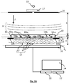
- the figure 1A represents an example of a device according to the invention.
- a light source 11 is capable of emitting a light wave 12, called an incident light wave, propagating towards a sample 10, along a propagation axis Z.
- the light wave is emitted along a spectral band ⁇ .
- Sample 10 is a sample comprising particles, among which particles of interest 10a which it is desired to enumerate.
- particles is meant for example cells, and in particular blood cells, but it can also be microorganisms, viruses, spores, or microbeads, usually used in biological applications, or also microalgae. They may also be droplets which are insoluble in a liquid medium 10 m, for example oil droplets dispersed in an aqueous phase.
- the particles 10a have a diameter, or are inscribed in a diameter, of less than 100 ⁇ m, and preferably less than 50 ⁇ m or 20 ⁇ m.
- the particles have a diameter, or are inscribed in a diameter, greater than 500 nm or 1 ⁇ m.
- the sample comprises a medium 10m in which the particles of interest 10a bathe.
- the particles 10a are, in this example, blood cells, for example red blood cells (erythrocytes) or white blood cells (leukocytes).
- the medium 10 m, in which the particles bathe can in particular be a liquid, for example blood plasma, optionally diluted.
- the sample 10 is, in this example, contained in a fluidic chamber 15.
- the thickness e of the sample 10, along the axis of propagation Z typically varies between 10 ⁇ m and 1 cm, and is preferably between 20 ⁇ m and 500 ⁇ m.
- the sample 10 extends along a plane P 10 , called the plane of the sample, preferably perpendicular to the axis of propagation Z. It is held on a support 10s at a distance d from an image sensor 16 .
- the distance D between the light source 11 and the sample 10 is preferably greater than 1 cm. It is preferably between 2 and 30 cm.
- the light source, seen by the sample is considered to be point. This means that its diameter (or its diagonal) is preferably less than a tenth, better still a hundredth of the distance between the sample and the light source.
- the light source 11 may be a light emitting diode as shown in figure figure 1A . It can be associated with a diaphragm 18, or spatial filter.
- the opening of the diaphragm is typically between 5 ⁇ m and 1 mm, preferably between 50 ⁇ m and 500 ⁇ m.
- the diaphragm is supplied by Thorlabs under the reference P150S and its diameter is 150 ⁇ m.
- the diaphragm can be replaced by an optical fiber, a first end of which is placed facing the light source 11 and a second end of which is placed opposite the sample 10.
- the device may include a diffuser 17, arranged between the light source 11 and the diaphragm 18.
- a diffuser 17 makes it possible to overcome the constraints of centering the light source 11 with respect to the opening of the. diaphragm 18.
- the function of such a diffuser is to distribute the light beam produced by the light source according to a cone of angle a.
- the angle of diffusion ⁇ varies between 10 ° and 80 °.
- the presence of such a diffuser makes it possible to make the device more tolerant with regard to an off-centering of the light source relative to the diaphragm, and to homogenize the illumination of the sample.
- the diaphragm is not necessary, in particular when the light source is sufficiently punctual, in particular when it is a laser source.
- the light source 11 can be a laser source, such as a laser diode. In this case, it is not useful to associate a spatial filter 18 or a diffuser 17 with it. Such a configuration is shown on the diagram. figure 1B .
- the spectral emission band ⁇ of the incident light wave 12 has a width of less than 100 nm.
- spectral bandwidth is meant a width at mid-height of said spectral band.
- the sample 10 is placed between the light source 11 and the image sensor 16 mentioned above.
- the latter preferably extends parallel, or substantially parallel to the plane P 10 along which the sample extends.
- the term substantially parallel means that the two elements may not be strictly parallel, an angular tolerance of a few degrees, less than 20 ° or 10 ° being allowed.
- the image sensor 16 is able to form an image I 0 according to a detection plane P 0 .
- a detection plane P 0 In the example shown, it is an image sensor comprising a matrix of pixels, of the CCD type or a CMOS.
- the detection plane P 0 preferably extends perpendicularly to the axis of propagation Z of the incident light wave 12.
- the distance d between the sample 10 and the matrix of pixels of the image sensor 16 is advantageously between 50 ⁇ m and 2 cm, preferably between 100 ⁇ m and 2 mm.
- the image I 0 acquired by the image sensor 16 comprises interference figures (or diffraction figures), each interference figure being generated by a particle 10a of sample 10.
- the processor is a microprocessor linked to a programmable memory 22 in which is stored a sequence of instructions for perform the image processing and calculation operations described in this description.
- the processor can be coupled to a screen 24 allowing the display of images acquired by the image sensor 16 or calculated by the processor 20.
- an image I 0 acquired on the image sensor 16 does not make it possible to obtain a sufficiently precise representation of the observed sample.
- a propagation operator h can be applied to each image acquired by the image sensor, so as to calculate a quantity representative of the exposure light wave 14.
- Such a method designated by the term holographic reconstruction, allows in particular to reconstruct an image of the modulus or of the phase of this light wave 14 in a reconstruction plane parallel to the detection plane P 0 , and in particular in the plane P 10 along which the sample extends.
- a convolution product of the image I 0 acquired by the image sensor 16 is carried out by a propagation operator h.
- the reconstruction surface can in particular be a reconstruction plane P z located at a distance
- of the image sensor 16, and in particular the plane P 10 of the sample, with: AT x y z I 0 x y z ⁇ h , * designating the operator product of convolution.
- the coordinates ( x, y ) denote a radial position in a plane perpendicular to the axis of propagation Z.
- the coordinate z denotes a coordinate along the axis of propagation Z.
- the previously mentioned surface is not necessarily planar, but it extends substantially parallel to the detection plane and is preferably a plane P z parallel to the detection plane.
- the image obtained from the modulus and / or from the phase of the complex image A z is designated by the term “reconstructed image” and is denoted I z .
- the inventors have developed a method for counting the particles 10a present in the sample according to a method described in connection with the figures 2A to 2E . The main steps of this process are described below.
- Step 100 illumination of the sample. During this step, the sample is illuminated by the light source 11.
- Step 110 acquisition of an image I 0 of the sample 10 by the image sensor 16, this image forming a hologram.
- One of the advantages of the lens-less configuration, shown on the figures 1A or 1B is the large field observed, making it possible to simultaneously address a high sample volume.
- the observed field depends on the size of the sensor, being slightly smaller than the detection surface of the latter, due to the spacing between the sensor and the sample.
- the field observed is generally greater than 10 mm 2 , or even 20 mm 2 .
- Step 120 calculation of a complex image A Z in a reconstruction plane P Z.
- the complex image comprises phase and amplitude information of the exposure light wave 14 to which the image sensor 16 is exposed.
- the reconstruction plane is the plane P 10 along which the sample extends. .
- Step 120 can be carried out by applying the propagation operator h, previously described, to an image resulting from the acquired image I 0 .
- the application of the propagation operator to the acquired image can result in a complex image A z affected by a significant reconstruction noise, frequently designated by the term twin image.
- iterative algorithms can be implemented. One of these algorithms is described below, in connection with the figures 4A and 4B .
- the reconstruction distance from the image sensor 16 is determined either a priori, knowing the position of the sample 10 relative to the image sensor 16, or on the basis of a digital focusing algorithm, according to which the optimal reconstruction distance is that for which the reconstructed image I Z is the sharpest.
- Numerical focusing algorithms are known to those skilled in the art.
- the figure 2B is an example of a part of an image reconstructed I Z from the module M z of a complex image A Z obtained according to a method implementing the steps described in connection with the figures 4A and 4B .
- the particles of interest 10a which it is desired to enumerate are red blood cells. They appear in the form of regions of interest ROI distributed in the reconstructed image and isolated from each other. The sample and the experimental conditions are described more precisely below, in connection with the experimental tests.
- Step 130 segmentation.
- the image formed during step 120 is subject to segmentation, so as to isolate the regions of interest ROI corresponding to particles.
- image segmentation is meant a partition of the image so as to group the pixels together, for example according to their intensity.
- Image segmentation results in a segmentation image I z ⁇ in which the regions of interest ROI, spaced from one another, are delimited, each region of interest possibly corresponding to a particle, or to a cluster of particles as described below.
- Different segmentation methods are known to those skilled in the art.
- Otsu thresholding can be applied, consisting in determining a value of an intensity threshold from the histogram of the image, the threshold allowing optimal separation of the pixels according to two classes: a class of pixels representing the regions of interest and a class of pixels representing the background of the image.
- the figure 2C represents the result of a segmentation of the image of the figure 2B by applying a thresholding according to Otsu's algorithm.
- the image obtained is binarized, the pixels representing the background of the image being dark (minimum gray level) while the pixels representing each area of interest ROI are light (maximum gray level).
- the segmentation image I z ⁇ resulting from this step results from a segmentation of the image M z of the modulus of the complex amplitude A z of the exposure light wave 14.
- the image resulting from this step results from a segmentation of the image ⁇ z of the phase of the exposure light wave.
- the segmentation image I z ⁇ can also combine the regions of interest appearing following the respective segmentations of the image M z of the module as well as of the image ⁇ z of the phase of the exposure light wave.
- a count of the particles of interest by a simple count of the regions of interest appearing on the segmentation image I z ⁇ can give a first order of magnitude on the quantity of particles of interest. But the inventors have found that such a numbering gives imprecise results. Indeed, certain regions of interest correspond to particles different from the particles that it is desired to count. Furthermore, certain regions of interest bring together several particles of interest, the latter forming clusters. This is due to the fact that certain particles of interest are close to each other, and are merged in the same region of interest. On the figures 1A and 1B clusters 10a 2 comprising two particles and clusters 10a 3 comprising three particles have been shown diagrammatically. These causes of error are addressed in the steps described below.
- Step 140 selection. During this step, a selection is made of the regions of interest determined during the previous step as a function of their morphology, that is to say as a function of a morphological criterion, the latter possibly being the area. , shape or size. This makes it possible to select the regions of interest corresponding to the particles of interest that one wishes to count.
- This step can include filtering of each region of interest according to the morphological criterion mentioned above, so as to select regions of interest representative of the particles of interest.
- the filtering makes it possible to select the regions of interest having a diameter of less than 100 ⁇ m, or inscribed in such a diameter. This makes it possible not to take into account large dust or traces, while retaining clusters of red blood cells.
- the notation ROI n corresponds to a region of interest considered, following the classification step, as comprising n particle (s), n being a strictly positive integer.
- a selection can be carried out as a function of the shape of each region of interest. For example, a larger diameter and a smaller diameter are determined for each region of interest. The ratio between the largest diameter and the smallest diameter makes it possible to quantify a form factor of the region of interest considered. According to this selection, it is possible to identify the regions of interest whose shape cannot be considered as spherical, these regions of interest not being considered as representative of particles of interest and not being taken into account in the numeration.
- the selection can comprise a comparison between the shape of each region of interest and a shape representative of the particle of interest, or of clusters of particles of interest, to be detected.
- a signal to noise ratio S / N can be established for each region of interest present in the segmentation image I z ⁇ .
- a signal-to-noise ratio can be calculated by making a ratio between an average value of pixels, called central pixels, located at the center of the region of interest, for example 9 central pixels, and the standard deviation calculated on a background of the image, the background of the image corresponding to the reconstructed image without the regions of interest.
- the figure 2E is a histogram of the values of the S / N ratios calculated for the different regions of interest identified on the sample shown on the figures 2C and 2D .
- Step 140 may also include filtering of regions of interest as a function of their signal to noise ratio S / N. Indeed, below a certain threshold, the signal-to-noise ratio is considered to be too low for a region of interest to be effectively considered to correspond to a particle.
- the figures 3A and 3B represent an example of filtering of regions of interest on the basis of a threshold value of the signal to noise ratio equal to 1.5.
- thresholding eliminates regions of interest with a low signal-to-noise ratio, the latter being surrounded by by a thick circle on the figure 3A .
- Regions of interest with a low S / N ratio do not appear on the figure 3B .
- the filtering of regions of interest based on the S / N ratio was limited to singlets.
- doublets are surrounded by an oval outline and triplets are surrounded by a square outline.
- This algorithm allows a gradual adjustment of the reference size on the basis of which the classification of the regions of interest is carried out. This allows a more precise classification to be obtained.
- step 140 makes it possible to select the regions of interest representative of the particles of interest, and / or to attribute a number of particle (s) to each region of interest considered as representative of particles of interest.
- Step 150 count.
- the regions of interest selected during step 140 that is to say considered as representative of particles, are counted, taking into account a number of particles possibly assigned to each of them. they.
- Step 120 described above can be carried out by performing a convolution between a propagation operator and the image acquired by the image sensor. However, the application of such an operator can generate significant reconstruction noise. In order to optimize the reconstruction, by limiting the reconstruction noise, step 120 can be implemented according to an algorithm as described in the patent application FR1652500 filed on March 23, 2016 . We will now describe, in connection with the figures 4A and 4B , the main steps of this algorithm.
- the complex image in the detection plane obtained during a previous iteration, noted AT 0 k - 1 is propagated in the reconstruction plane P z , to form a complex image AT z k in the reconstruction plan P z .
- Each iteration consists of adjusting the phase ⁇ 0 k complex image AT 0 k in the detection plane P 0 as a function of a noise criterion ⁇ k determined from the complex image AT z k .
- Step 121 propagation of the detection plane to the reconstruction plane
- the image formed in the detection plane P 0 is available .
- We assign an arbitrary value, for example 0, to the phase ⁇ 0 k 0 of the initial image.
- the image in the detection plane is the complex image AT 0 k - 1 resulting from the previous iteration.
- the image formed in the detection plane P 0 is propagated in the reconstruction plane P z , by applying a propagation operator h as previously described, so as to obtain a complex image AT z k , representative of sample 10, in the reconstruction plane P z .
- the index -z represents the fact that the propagation is carried out in a direction opposite to the axis of propagation Z. We speak of backpropagation.
- Step 122 Calculation of an indicator in several pixels
- ⁇ k ( x, y) associated with each pixel of a plurality of pixels ( x, y ) of the complex image AT z k , and preferably in each of its pixels.
- This magnitude depends on the value AT z k x y of the image AT z k , or its modulus, at the pixel (x, y) at which it is calculated. It can also depend on a dimensional derivative of the image in this pixel, for example the modulus of a dimensional derivative of this image.
- the quantity ⁇ k ( x, y ) associated with each pixel is a modulus a difference in the image AT z k , in each pixel, and the value 1.
- the quantities ⁇ k ( x, y ) are calculated in several pixels of the complex image AT z k . These magnitudes can form a vector E k , whose terms are the magnitudes ⁇ k ( x, y ) associated with each pixel ( x , y ).
- an indicator called a noise indicator, is calculated from a norm of the vector E k .
- the magnitude ⁇ k ( x, y ) calculated from the complex image AT z k , at each pixel ( x, y ) of the latter, is summed so as to constitute a noise indicator ⁇ k associated with the complex image AT ref k .
- An important aspect of this step consists in determining, in the detection plane P 0 , phase values ⁇ 0 k x y of each pixel of the image AT 0 k in the plane of the sample, making it possible to obtain, during a following iteration, a reconstructed image AT z k + 1 whose noise indicator ⁇ k +1 is less than the noise indicator ⁇ k .
- the algorithm proceeds to a progressive adjustment of the phase ⁇ 0 k x y in the detection plane P 0 , so as to gradually minimize the indicator ⁇ k .
- the image AT 0 k in the detection plane is representative of the light wave 14 in the detection plane P 0 , both from the point of view of its intensity and of its phase.
- Steps 120 to 125 aim to establish, iteratively, the value of the phase ⁇ 0 k x y of each pixel of the image AT 0 k , minimizing the indicator ⁇ k , the latter being obtained on the image AT z k obtained by image propagation AT 0 k - 1 in the reconstruction plan P z .
- the minimization algorithm can be a gradient descent algorithm, or a conjugate gradient descent algorithm, the latter being described below.
- Step 124 Adjustment of the value of the phase in the detection plane.
- Im represents the imaginary part operator and r ' represents a coordinate ( x, y ) in the detection plane.
- the step ⁇ k can vary according to the iterations, for example between 0.03 during the first iterations and 0.0005 during the last iterations.
- the update equation provides a fit of the vector ⁇ 0 k , which results in an iterative update of the phase ⁇ 0 k x y in each pixel of the complex image AT 0 k .
- This complex image AT 0 k in the detection plane, is then updated by these new values of the phase associated with each pixel.
- Step 125 Reiteration or exit from the algorithm.
- step 125 consists in reiterating the algorithm, by a new iteration of steps 121 to 125 on the basis of the complex image AT 0 k updated during step 124.
- the convergence criterion can be a predetermined number K of iterations, or a minimum value of the gradient ⁇ ⁇ k of the indicator, or a difference considered to be negligible between two phase vectors ⁇ 0 k - 1 , ⁇ 0 k consecutive.
- Step 126 Obtaining the complex image in the reconstruction plane.
- the coefficient r 2 is the coefficient of determination associated with each linear regression of the Passing-Bablok type.
- the figure 6A represents an image of the modulus of the complex image in the reconstruction plane P z , the latter being a plane along which the sample extends.
- the figure 6B represents the image of the figure 6A after segmentation, binarization and detection of clusters comprising two white blood cells. These are surrounded by a white ring.
- the identification of singlets and doublets allows a more precise quantification of white blood cells, compared to a simple enumeration of the regions of interest.
- the figures 6C and 6D correspond respectively to figures 6A and 6B on another sample. The acquisition was carried out using a laser type light source, as previously described.
- the method was also tested, during a third series of tests, on glass beads with a diameter of 5 ⁇ m.
- These reference beads Bangs Laboratories - SS06N, diluted to 1/2000 th in a saline buffer type PBS.
- the acquisition was carried out using a laser type light source, as previously described.
- the detection of a cluster comprising two balls is observed.
- the figure 7A represents an image of the modulus of the complex image in the reconstruction plane P z , the latter being a plane along which the sample extends.
- the figure 7B represents the image of the figure 7A after segmentation, binarization and detection of clusters comprising two beads, these clusters being surrounded by a white outline.
- the inventors estimate that it is preferable for the surface density of particles of interest to be counted to be less than 2000 particles per mm 2 of detection surface. Beyond that, the particles are too close to each other, which degrades the signal-to-noise ratio of each region of interest. Also, it is advantageous to estimate, according to the different scenarios, a maximum surface density, and to adapt the dilution to be applied to the sample accordingly.
- One of the targeted applications is the counting of blood cells, the latter possibly being white blood cells, red blood cells or platelets.
- the inventors have found that when it comes to white blood cells or red blood cells, during step 120, it is preferable that the reconstructed image I z represents the modulus of the complex amplitude A z in the plane of reconstruction P z .
- the definition of the edges of the regions of interest, corresponding to the cells, is clearer.
- the reconstructed image I z represents the phase of the complex amplitude A z in the reconstruction plane P z
- Les figures 8A and 8B represent a histogram of the signal-to-noise ratio of regions of interest corresponding to red blood cells, based respectively on the modulus or the phase of the reconstructed complex image.
- the number of red blood cells considered was respectively equal to 12166 and 12888.
- a higher signal-to-noise ratio is observed when based on an image of the module (average of 18.6) than when based on a phase image ( average of 13.9).
- red blood cells were illuminated in a blue spectral band.
- the inventors carried out experimental tests. Following these tests, they defined the variants described below, each variant being able to be combined with all or part of the steps described above.
- the digital focusing algorithm is established by considering a lower focusing limit d inf , and an upper focusing limit d sup .
- the determined focusing distance is either less than or equal to the limit d inf , or greater than or equal to the limit d sup , the focusing distance is taken to be equal to the mean (or median) focusing distance d mean described above.
- the focusing algorithm provides at least one focusing distance d p less than or equal to d inf or greater than or equal to d sup , it is likely that this is an incorrect focusing distance.
- the focusing distance is therefore replaced by the distance d mean , the latter being considered as more probable.
- the segmentation is carried out according to an Otsu thresholding.
- the value of the segmentation threshold thus obtained is compared with the mode of the histogram of the reconstructed image I z , whether it is a phase image or an image of the module, or their combination, of the 'reconstructed image.
- the histogram mode corresponds at a pixel intensity level corresponding to the maximum of the histogram of the reconstructed image. If the segmentation threshold determined by Otsu's thresholding is greater than 90% of the histogram mode, the applied segmentation threshold is arbitrarily set at a certain percentage of the histogram mode, for example between 80% and 85% of histogram mode.
- a quality criterion Q of the image is determined I z ⁇ segmented during step 130.
- the process is interrupted.
- the maximum area A max can be determined by a person skilled in the art on the basis of experimental tests.
- the signal to noise ratio SNR I z ⁇ of the segmented image I z ⁇ corresponds to an intensity level I ROI in the different regions of interest ROI segmented during step 130, normalized by an estimate of the noise N out outside the regions of interest.
- the intensity level I ROI can be estimated by a mean value ⁇ or a median value med of the intensity in the different regions of interest ROI.
- the signal-to-noise ratio thus defined is then compared with a predetermined signal-to-noise ratio threshold SNR min .
- SNR I z ⁇ the signal to noise ratio
- the segmented image is considered valid. Otherwise, the segmented image is invalidated.
- At least one quality criterion Q is determined relative to the segmented image I z ⁇ .
- the quality criterion can correspond to a comparison between an area A of all the regions of interest segmented during step 130, with a predefined maximum area A max .
- the segmented image is validated or invalidated.
- an auxiliary quality criterion Q ' is determined. It can be a comparison between the signal to noise ratio SNR I z ⁇ of the segmented image, as previously defined, with a minimum signal to noise ratio SNR min . Depending on this comparison, the segmented image is validated or invalidated.
- This variant was applied to 305 samples, the particles being red blood cells. It made it possible to invalidate images corresponding to particular cases such as empty images, images on which the number of particles is too low or too large, or images resulting from a problem that arose during acquisition.
- the count of the particles of interest is validated.
- the level of acceptance L max can be adjusted, by a person skilled in the art, during an experimental learning phase.
- the count of the particles of interest is invalidated and this invalidation is signaled.
- Such a situation may for example correspond to blood comprising cold agglutinins.
- the blood contains numerous clusters of red blood cells, comprising a number of red blood cells greater than the maximum number of acceptable red blood cells N.
- the inventors have observed that the number of regions of interest rejected could reach several dozen or even several hundred. Considering the number of regions of interest rejected, the red blood cell count is greatly underestimated.
- the level of acceptance L max can be defined by a person skilled in the art during experimental tests.
- the invention can be applied to the enumeration of particles of interest in the blood, but also in other body fluids such as urine, saliva, semen, etc. It can also be applied in the quantification of microorganisms, for example. bacteria or bacterial colonies. Beyond applications related to biology or health, the invention can be implemented in the control of samples in industrial fields or the control of the environment, for example the food industry or the control of fluids. industrial.
Landscapes
- Engineering & Computer Science (AREA)
- Physics & Mathematics (AREA)
- General Physics & Mathematics (AREA)
- Chemical & Material Sciences (AREA)
- General Health & Medical Sciences (AREA)
- Health & Medical Sciences (AREA)
- Life Sciences & Earth Sciences (AREA)
- Theoretical Computer Science (AREA)
- Analytical Chemistry (AREA)
- Biochemistry (AREA)
- Pathology (AREA)
- Signal Processing (AREA)
- Biomedical Technology (AREA)
- Dispersion Chemistry (AREA)
- Molecular Biology (AREA)
- Multimedia (AREA)
- Immunology (AREA)
- Computing Systems (AREA)
- Investigating Or Analysing Materials By Optical Means (AREA)
- Computer Vision & Pattern Recognition (AREA)
- Investigating Or Analysing Biological Materials (AREA)
- Holo Graphy (AREA)
- Apparatus Associated With Microorganisms And Enzymes (AREA)
- Measuring Or Testing Involving Enzymes Or Micro-Organisms (AREA)
Claims (20)
- Verfahren zum Zählen von Partikeln (10a), Partikel von Interesse genannt, die in einer Probe (10) angeordnet sind, wobei das Verfahren die folgenden Schritte umfasst:a) Beleuchten der Probe (10) mithilfe einer Lichtquelle (11), wobei die Lichtquelle eine einfallende Lichtwelle (12) aussendet, die sich zur Probe (10) hin ausbreitet;b) Erfassen, mithilfe eines Bildsensors (16), eines Bildes (I 0) der Probe (10), das in einer Detektionsebene (P 0) gebildet wird, wobei die Probe zwischen der Lichtquelle (11) und dem Bildsensor (16) angeordnet ist, wobei jedes Bild für eine Lichtwelle (14), Belichtungslichtwelle genannt, repräsentativ ist, mit welcher der Bildsensor (16) unter der Wirkung der Beleuchtung belichtet wird;
wobei das Verfahren dadurch gekennzeichnet ist, dass es ferner die folgenden Schritte umfasst:c) ausgehend von dem im Schritt b) erfassten Bild (I 0), Anwenden eines Ausbreitungsoperators (h), so dass ein komplexer Ausdruck (Az ) der Belichtungslichtwelle (14) berechnet wird, gemäß einer Rekonstruktionsfläche (Pz ), die sich gegenüber der Detektionsebene (P 0) erstreckt;d) Bilden eines Bildes (Iz, Mz, ϕz ), rekonstruiertes Bild genannt, das für eine Verteilung des Moduls oder der Phase des komplexen Ausdrucks gemäß der Rekonstruktionsfläche repräsentativ ist;e) Segmentieren des im Schritt d) gebildeten Bildes, um ein Segmentierungsbild f) Bestimmen einer Größe von Bereichen von Interesse und Klassifizieren der Bereiche von Interessen in Abhängigkeit von ihrer Größe gemäß mindestens einer der folgenden Klassen:- eine Klasse, gemäß welcher der Bereich von Interesse einen einzigen Partikel von Interesse beinhaltet;- eine Klasse, gemäß welcher der Bereich von Interesse eine ganzzahlige Anzahl größer 1 von Partikeln von Interesse beinhaltet;g) Zählen der Partikel von Interesse ausgehend von den Bereichen von Interesse, die im Schritt f) Gegenstand einer Klassifizierung waren.
 - Verfahren nach Anspruch 1, bei dem der Schritt f) vor der Klassifizierung beinhaltet:- ein Bestimmen mindestens eines morphologischen Kriteriums für jeden Bereich von Interesse;- ein Auswählen der Bereiche von Interesse (ROI) in Abhängigkeit von dem morphologischen Kriterium, wobei die Klassifizierung an den ausgewählten Bereichen von Interesse ausgeführt wird.
- Verfahren nach Anspruch 2, bei dem mindestens ein morphologisches Kriterium unter einem Durchmesser, einer Größe oder einem Formfaktor jedes Bereichs von Interesse gewählt wird.
- Verfahren nach einem der vorhergehenden Ansprüche, bei dem der Schritt f) ein Berücksichtigen einer Referenzgröße (Sref ) beinhaltet, die für eine vorbestimmte Zahl von Partikel von Interesse repräsentativ ist, wobei die Klassifizierung in Abhängigkeit von der Referenzgröße ausgeführt wird.
- Verfahren nach einem der vorhergehenden Ansprüche, bei dem der Schritt f) die folgenden Teilschritte beinhaltet:fi) eine erste Klassifizierung der Bereiche von Interesse, die in Abhängigkeit von einer ersten Referenzgröße (Sref - 1) ausgeführt wird, wobei die erste Referenzgröße einer vorbestimmten Anzahl von Partikeln von Interesse entspricht;fii) nach der ersten Klassifizierung ein Bestimmen einer zweiten Referenzgröße (Sref - 2) ausgehend von den Bereichen von Interesse, die im Teilschritt fi) als eine vorbestimmte Anzahl von Partikeln von Interesse enthaltend klassifiziert worden;fiii) eine zweite Klassifizierung der Bereiche von Interesse, die in Abhängigkeit von der im Teilschritt fii) bestimmten zweiten Referenzgröße (Sref - 2) ausgeführt wird.
- Verfahren nach einem der vorhergehenden Ansprüche, bei dem der Schritt f) vor der Klassifizierung beinhaltet:- ein Berechnen eines Signal-Rausch-Verhältnisses (S/R) mehrerer Bereiche von Interesse (ROI);- ein Auswählen der Bereiche von Interesse (ROI) in Abhängigkeit von dem für jeden von ihnen berechneten Signal-Rausch-Verhältnis (S/R), wobei die Klassifizierung an den so ausgewählten Bereichen von Interesse ausgeführt wird.
- Verfahren nach einem der vorhergehenden Ansprüche, bei dem die Probe vor dem Schritt b) mit einem Sphärisierungsreagens gemischt wird, um die Form der Partikel von Interesse (10a) so zu ändern, dass sie kugelförmig gemacht wird.
- Verfahren nach einem der vorhergehenden Ansprüche, bei dem der Schritt c) die folgenden Teilschritte beinhaltet:ci) Definieren eines Ausgangsbildes der Probe
 cii) Bestimmen eines komplexen Bildes der Probe

 ciii) Berechnen eines Rauschindikators (εk ) ausgehend von dem im Teilschritt cii) bestimmten komplexen Bildes
 civ) Aktualisieren des Bildes der Probe
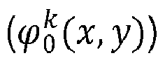 cv) Reiteration der Teilschritte cii) bis civ) bis zum Erreichen eines Konvergenzkriteriums, so dass ein komplexes Bild der Probe (10) in der Detektionsebene (P 0) und in der Rekonstruktionsfläche (Pz ) erhalten wird.
 - Verfahren nach einem der vorhergehenden Ansprüche, bei dem keine Bildformungsoptik zwischen der Probe (10) und dem Bildsensor (16) angeordnet ist.
- Verfahren nach einem der vorhergehenden Ansprüche, bei dem die Partikel von Interesse Blutzellen sind.
- Verfahren nach Anspruch 10, bei dem im Schritts d):- die Partikel von Interesse (10a) rote Blutkörperchen oder weiße Blutkörperchen sind, wobei das rekonstruierte Bild für eine Verteilung des Moduls des komplexen Ausdrucks (Az ) gemäß der Rekonstruktionsfläche (Pz ) repräsentativ ist;- die Partikel von Interesse (10a) Blutplättchen sind, wobei das rekonstruierte Bild für eine Verteilung einer Phase des komplexen Ausdrucks (Az ) gemäß der Rekonstruktionsfläche (Pz ) repräsentativ ist.
- Verfahren nach einem der vorhergehenden Ansprüche, bei dem der Schritt c) eine Anwendung eines Algorithmus zur numerischen Fokussierung umfasst, so dass eine Fokussierungsdistanz bestimmt wird, die der Rekonstruktionsdistanz entspricht, in der sich die Rekonstruktionsfläche (Pz ) erstreckt.
- Verfahren nach Anspruch 12, bei dem im Schritt c) das im Schritt b) erfasste Bild in verschiedene, voneinander getrennte Zonen eingeteilt wird und bei dem der Algorithmus zur numerischen Fokussierung in jeder Zone angewandt wird, so dass für jede von ihnen eine Fokussierungsdistanz (dp ) erhalten wird, wobei der Schritt c) auch beinhaltet:- ein Berücksichtigen eines maximalen Streuungsmaßes (δmax );- ein Berechnen eines Streuungsmaßes (δ(dp )), das eine Streuung der erhaltenen Fokussierungsdistanzen (dp ) repräsentiert;- einen Vergleich zwischen dem berechneten Streuungsmaß (δ(dp )) und dem maximalen Streuungsmaß (δmax ),- in Abhängigkeit von dem Vergleich:• ein Berechnen eines Mittels oder eines Medians (
dp ) der für jede Zone erhaltenen Fokussierungsdistanzen (dp ), wobei das Mittel oder der Median dann die im Schritt c) berücksichtigte Fokussierungsdistanz bildet;• oder eine Berücksichtigung von gespeicherten Fokussierungsdistanzen, um die im Schritt c) berücksichtigte Fokussierungsdistanz (dmean ) zu ermitteln. - Verfahren nach Anspruch 13, bei dem das Streuungsmaß (δ(dp )) eine Abweichung zwischen einer maximalen Fokussierungsdistanz (d p-max ) und einer minimalen Fokussierungsdistanz (d p-min ) oder eine Varianz oder eine Standardabweichung der erhaltenen Fokussierungsdistanzen (dp ) ist.
- Verfahren nach Anspruch 12, bei dem im Schritt c) das im Schritt b) erfasste Bild in verschiedene, voneinander getrennte Zonen eingeteilt wird und bei dem der Algorithmus zur numerischen Fokussierung in jeder Zone angewandt wird, so dass für jede von ihnen eine Fokussierungsdistanz (dp )erhalten wird, wobei der Schritt c) auch beinhaltet:- ein Berücksichtigen eines unteren Fokussierungsgrenzwerts (dinf );- ein Berücksichtigen eines oberen Fokussierungsgrenzwerts (dsup );- ein Vergleichen jeder Fokussierungsdistanz (dp ) mit dem unteren Fokussierungsgrenzwert (dinf ) und mit dem oberen Fokussierungsgrenzwert (dsup );- in Abhängigkeit von dem Vergleich:• wenn die Fokussierungsdistanz zwischen dem unteren Fokussierungsgrenzwert (dinf ) und der oberen Fokussierungsdistanz (dsup ) liegt, Berechnen eines Mittels oder eines Medians (
dp ) der für jede Zone erhaltenen Fokussierungsdistanzen (dp ), wobei das Mittel oder der Median dann die im Schritt c) berücksichtigte Fokussierungsdistanz bildet;• wenn die Fokussierungsdistanz (dp ) kleiner oder gleich dem unteren Fokussierungsgrenzwert (dinf ) oder größer oder gleich dem oberen Fokussierungsgrenzwert (dsup ) ist, Berücksichtigen von gespeicherten Fokussierungsdistanzen, um die in Schritt c) berücksichtigte Fokussierungsdistanz (dmean ) zu ermitteln. - Verfahren nach einem der vorhergehenden Ansprüche, bei dem der Schritt e) umfasst:- ein Bestimmen eines Modus des Histogramms des rekonstruierten Bildes (Iz , Mz, ϕz ), der einer Intensität einer maximalen Anzahl von Pixeln des rekonstruierten Bildes entspricht;- eine Ausführung eines Schwellenwertverfahrens von Otsu, so dass ein Segmentierungsschwellenwert erhalten wird, auf dessen Grundlage die Segmentierung des rekonstruierten Bildes ausgeführt wird;- einen Vergleich zwischen dem Modus des Histogramms und dem Segmentierungsschwellenwert, so dass, wenn der Segmentierungsschwellenwert mehr als 90 % des Modus des Histogramms beträgt, der Segmentierungsschwellenwert auf einen Prozentsatz zwischen 80 % und 85 % des Modus des Histogramms festgelegt wird.
- Verfahren nach einem der vorhergehenden Ansprüche, bei dem der Schritt c) ein Bestimmen eines Qualitätskriteriums (Q) des segmentierten Bildes
 - ein Berücksichtigen eines vorbestimmten maximalen Flächeninhalts (Amax );- ein Bestimmen des Flächeninhalts (A) sämtlicher Bereiche von Interesse (ROI) des segmentierten Bildes
 - ein Vergleichen des Flächeninhalts (A) sämtlicher Bereiche von Interesse mit dem maximalen Flächeninhalt (Amax );- in Abhängigkeit von dem Vergleich, Verwerfen oder Validieren des segmentierten Bildes
- Verfahren nach Anspruch 17, bei dem, wenn das segmentierte Bild
 - ein Berücksichtigen eines vorbestimmten minimalen Signal-Rausch-Verhältnisses (SNRmin );- ein Berechnen eines Signal-Rausch-Verhältnisses
 - einen Vergleich zwischen dem Signal-Rausch-Verhältnis des segmentierten Bildes
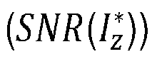 - in Abhängigkeit von dem Vergleich, Verwerfen oder Validieren des segmentierten Bildes
- Verfahren nach einem der vorhergehenden Ansprüche, bei dem im Schritt f) die Bereiche von Interesse, deren Größe eine maximale Größe (Smax ) überschreitet, verworfen werden, wobei das Verfahren beinhaltet:- ein Bestimmen der Anzahl von Bereichen von Interesse, die im Schritt f) verworfen wurden;- ein Berücksichtigen eines vorbestimmten Annahmeniveaus (Lmax );- einen Vergleichen zwischen der Anzahl der Bereiche von Interesse, die im Schritt f) verworfen wurden, und dem Annahmeniveau (Lmax ), in Abhängigkeit von dem die im Schritt g) durchgeführte Zählung der Partikel validiert wird oder nicht.
- Vorrichtung zum Zählen von Partikeln von Interesse (10a), die in einer Probe (10) angeordnet sind, wobei die Vorrichtung beinhaltet:- eine Lichtquelle (11) der geeignet ist, eine einfallende Lichtwelle (12) auszusenden, die sich zur Probe (10) hin ausbreitet;- einen Träger (10s), der dazu ausgestaltet ist, die Probe (10) zwischen der Lichtquelle (11) und dem Bildsensor (16) zu halten;einen Prozessor (20), der dazu ausgestaltet ist, ein vom Bildsensor (16) erfasstes Bild der Probe zu empfangen und die Schritte c) bis g) des Verfahrens nach einem der Ansprüche 1 bis 19 auszuführen.
Applications Claiming Priority (2)
| Application Number | Priority Date | Filing Date | Title |
|---|---|---|---|
| FR1663028A FR3060746B1 (fr) | 2016-12-21 | 2016-12-21 | Procede de numeration de particules dans un echantillon par imagerie sans lentille |
| PCT/FR2017/053725 WO2018115734A1 (fr) | 2016-12-21 | 2017-12-20 | Procédé de numération de particules dans un échantillon par imagerie sans lentille |
Publications (2)
| Publication Number | Publication Date |
|---|---|
| EP3559631A1 EP3559631A1 (de) | 2019-10-30 |
| EP3559631B1 true EP3559631B1 (de) | 2021-01-06 |
Family
ID=58228274
Family Applications (1)
| Application Number | Title | Priority Date | Filing Date |
|---|---|---|---|
| EP17829258.7A Active EP3559631B1 (de) | 2016-12-21 | 2017-12-20 | Verfahren zum zählen von partikeln in einer probe durch linsenlose bildgebung |
Country Status (5)
| Country | Link |
|---|---|
| US (1) | US11199488B2 (de) |
| EP (1) | EP3559631B1 (de) |
| JP (1) | JP6986083B2 (de) |
| FR (1) | FR3060746B1 (de) |
| WO (1) | WO2018115734A1 (de) |
Families Citing this family (11)
| Publication number | Priority date | Publication date | Assignee | Title |
|---|---|---|---|---|
| FR3086758B1 (fr) | 2018-09-28 | 2020-10-02 | Commissariat Energie Atomique | Procede et dispositif d'observation d'un echantillon sous lumiere ambiante |
| FR3088430B1 (fr) | 2018-11-09 | 2023-12-08 | Commissariat Energie Atomique | Dispositif microfluidique de preparation d'echantillons offrant une grande repetabilite |
| JP7582637B2 (ja) * | 2018-11-21 | 2024-11-13 | マイクロコントロールシステムズ株式会社 | 対象物計数システム、装置及び方法、並びに対象物計数管理システム |
| FR3090107B1 (fr) | 2018-12-18 | 2020-12-25 | Commissariat Energie Atomique | Procédé de caractérisation d'une particule à partir d'un hologramme. |
| FR3115372B1 (fr) | 2020-10-20 | 2022-12-02 | Biomerieux Sa | Procédé d'imagerie holographique numérique supprimant l'image jumelle |
| CN113176230B (zh) * | 2021-03-30 | 2022-12-13 | 西安理工大学 | 一种基于微流控无透镜成像的红细胞识别与姿态估计方法 |
| FR3131376B1 (fr) * | 2021-12-29 | 2023-11-10 | Commissariat Energie Atomique | Procédé d’estimation d’une distribution spatiale tridimensionnelle de fluorescence, à l’intérieur d’un objet. |
| WO2023195490A1 (ja) * | 2022-04-06 | 2023-10-12 | 富士フイルム株式会社 | 撮像システム及び細胞濃度調整方法 |
| CN115616884B (zh) * | 2022-09-26 | 2024-10-01 | 中国工程物理研究院激光聚变研究中心 | 一种基于物体轴向移动的全场复振幅无透镜成像方法 |
| CN115661074B (zh) * | 2022-10-26 | 2026-03-03 | 华中科技大学 | 基于血小板α颗粒超分辨率图像的血小板分类方法及系统 |
| CN121708405B (zh) * | 2026-02-12 | 2026-04-17 | 山东大学 | 基于无透镜成像和机器学习的变压器油污染度评估方法 |
Family Cites Families (14)
| Publication number | Priority date | Publication date | Assignee | Title |
|---|---|---|---|---|
| JP3411112B2 (ja) * | 1994-11-04 | 2003-05-26 | シスメックス株式会社 | 粒子画像分析装置 |
| WO2003021231A2 (en) * | 2001-09-05 | 2003-03-13 | Genicon Sciences Corporation | Method and apparatus for normalization and deconvolution of assay data |
| US20060120428A1 (en) * | 2004-12-08 | 2006-06-08 | Dae Kon Oh | Distributed feedback (DFB) semiconductor laser and fabrication method thereof |
| SE528697C2 (sv) * | 2005-03-11 | 2007-01-30 | Hemocue Ab | Volymetrisk bestämning av antalet vita blodkroppar i ett blodprov |
| CA2607609C (en) * | 2005-05-13 | 2014-07-15 | Tripath Imaging, Inc. | Methods of chromogen separation-based image analysis |
| DE102005037253A1 (de) * | 2005-08-08 | 2007-02-15 | Robert Bosch Gmbh | Messgerät |
| GB0701201D0 (en) | 2007-01-22 | 2007-02-28 | Cancer Rec Tech Ltd | Cell mapping and tracking |
| WO2011049965A1 (en) * | 2009-10-20 | 2011-04-28 | The Regents Of The University Of California | Incoherent lensfree cell holography and microscopy on a chip |
| CN103238120B (zh) * | 2010-11-12 | 2016-08-10 | 布鲁塞尔大学 | 用于表征透明颗粒的光学方法 |
| WO2012082776A2 (en) * | 2010-12-14 | 2012-06-21 | The Regents Of The University Of California | Method and device for holographic opto-fluidic microscopy |
| CN103608110B (zh) * | 2011-03-09 | 2017-06-06 | 彼克斯赛尔医疗科技有限公司 | 用于制备用于分析的包含细胞的样品流体的一次性盒子 |
| US10176363B2 (en) * | 2014-06-16 | 2019-01-08 | Siemens Healthcare Diagnostics Inc. | Analyzing digital holographic microscopy data for hematology applications |
| FR3034196B1 (fr) * | 2015-03-24 | 2019-05-31 | Commissariat A L'energie Atomique Et Aux Energies Alternatives | Procede d'analyse de particules |
| FR3034197B1 (fr) * | 2015-03-24 | 2020-05-01 | Commissariat A L'energie Atomique Et Aux Energies Alternatives | Procede de determination de l'etat d'une cellule |
-
2016
- 2016-12-21 FR FR1663028A patent/FR3060746B1/fr not_active Expired - Fee Related
-
2017
- 2017-12-20 US US16/471,429 patent/US11199488B2/en active Active
- 2017-12-20 EP EP17829258.7A patent/EP3559631B1/de active Active
- 2017-12-20 WO PCT/FR2017/053725 patent/WO2018115734A1/fr not_active Ceased
- 2017-12-20 JP JP2019533217A patent/JP6986083B2/ja active Active
Non-Patent Citations (1)
| Title |
|---|
| None * |
Also Published As
| Publication number | Publication date |
|---|---|
| US20210131944A1 (en) | 2021-05-06 |
| US11199488B2 (en) | 2021-12-14 |
| EP3559631A1 (de) | 2019-10-30 |
| WO2018115734A1 (fr) | 2018-06-28 |
| FR3060746B1 (fr) | 2019-05-24 |
| JP6986083B2 (ja) | 2021-12-22 |
| JP2020514704A (ja) | 2020-05-21 |
| FR3060746A1 (fr) | 2018-06-22 |
Similar Documents
| Publication | Publication Date | Title |
|---|---|---|
| EP3559631B1 (de) | Verfahren zum zählen von partikeln in einer probe durch linsenlose bildgebung | |
| EP3274689B1 (de) | Verfahren und vorrichtung zur analyse von partikeln | |
| EP3274694B1 (de) | Verfahren zur bestimmung des zustandes einer zelle | |
| EP3433679B1 (de) | Verfahren zur beobachtung einer probe durch berechnung eines komplexen bildes | |
| EP3218769B1 (de) | Analyseverfahren mit holographischer bestimmung einer position eines biologischen partikels | |
| EP3234550B1 (de) | Verfahren zur identifizierung biologischer partikel mit stapeln von defokussierten holografischen bildern | |
| EP3433678A1 (de) | Holographisches verfahren zur charakterisierung eines partikels in einer probe | |
| EP3519899B1 (de) | Vorrichtung zur beobachtung einer probe und verfahren zur beobachtung einer probe | |
| EP3397944B1 (de) | Vorrichtung und verfahren zur bimodalen beobachtung eines objekts | |
| EP3637194A1 (de) | Verfahren zu bestimmung der parameter eines teilchens | |
| EP3899669B1 (de) | Verfahren zur charakterisierung eines teilchens auf der basis eines hologramms | |
| EP3520022B1 (de) | Verfahren zur zählung von leukozyten in einer probe | |
| EP2872871A1 (de) | Verfahren und system zur rekonstruktion der optischen eigenschaften von in einem flüssigmedium gebadeten, lichtbrechenden objekten | |
| EP4217713A1 (de) | Verfahren zur analyse einer biologischen probe mit bestimmung der räumlichen verteilung von biomasse entlang der optischen achse | |
| FR3082943A1 (fr) | Procede de comptage de particules de petite taille dans un echantillon | |
| WO2019135060A1 (fr) | Système d'imagerie holographique et procédé d'analyse par imagerie holographique avec détection de défauts dans la chambre d'observation | |
| WO2025099033A1 (fr) | Appareil et procédé de micro-spectrométrie raman confocal avec système de mise au point | |
| FR3144371A1 (fr) | Procédé de traitement d’une image d’un échantillon comportant des particules biologiques |
Legal Events
| Date | Code | Title | Description |
|---|---|---|---|
| STAA | Information on the status of an ep patent application or granted ep patent |
Free format text: STATUS: UNKNOWN |
|
| STAA | Information on the status of an ep patent application or granted ep patent |
Free format text: STATUS: THE INTERNATIONAL PUBLICATION HAS BEEN MADE |
|
| PUAI | Public reference made under article 153(3) epc to a published international application that has entered the european phase |
Free format text: ORIGINAL CODE: 0009012 |
|
| STAA | Information on the status of an ep patent application or granted ep patent |
Free format text: STATUS: REQUEST FOR EXAMINATION WAS MADE |
|
| 17P | Request for examination filed |
Effective date: 20190618 |
|
| AK | Designated contracting states |
Kind code of ref document: A1 Designated state(s): AL AT BE BG CH CY CZ DE DK EE ES FI FR GB GR HR HU IE IS IT LI LT LU LV MC MK MT NL NO PL PT RO RS SE SI SK SM TR |
|
| AX | Request for extension of the european patent |
Extension state: BA ME |
|
| DAV | Request for validation of the european patent (deleted) | ||
| DAX | Request for extension of the european patent (deleted) | ||
| GRAP | Despatch of communication of intention to grant a patent |
Free format text: ORIGINAL CODE: EPIDOSNIGR1 |
|
| STAA | Information on the status of an ep patent application or granted ep patent |
Free format text: STATUS: GRANT OF PATENT IS INTENDED |
|
| RIC1 | Information provided on ipc code assigned before grant |
Ipc: G03H 1/04 20060101ALI20200629BHEP Ipc: G03H 1/08 20060101ALI20200629BHEP Ipc: G01N 15/14 20060101AFI20200629BHEP Ipc: G01N 15/00 20060101ALI20200629BHEP Ipc: G06K 9/00 20060101ALI20200629BHEP |
|
| INTG | Intention to grant announced |
Effective date: 20200714 |
|
| GRAS | Grant fee paid |
Free format text: ORIGINAL CODE: EPIDOSNIGR3 |
|
| GRAA | (expected) grant |
Free format text: ORIGINAL CODE: 0009210 |
|
| STAA | Information on the status of an ep patent application or granted ep patent |
Free format text: STATUS: THE PATENT HAS BEEN GRANTED |
|
| AK | Designated contracting states |
Kind code of ref document: B1 Designated state(s): AL AT BE BG CH CY CZ DE DK EE ES FI FR GB GR HR HU IE IS IT LI LT LU LV MC MK MT NL NO PL PT RO RS SE SI SK SM TR |
|
| REG | Reference to a national code |
Ref country code: GB Ref legal event code: FG4D Free format text: NOT ENGLISH |
|
| REG | Reference to a national code |
Ref country code: AT Ref legal event code: REF Ref document number: 1352898 Country of ref document: AT Kind code of ref document: T Effective date: 20210115 Ref country code: CH Ref legal event code: EP |
|
| REG | Reference to a national code |
Ref country code: DE Ref legal event code: R096 Ref document number: 602017031138 Country of ref document: DE |
|
| REG | Reference to a national code |
Ref country code: IE Ref legal event code: FG4D Free format text: LANGUAGE OF EP DOCUMENT: FRENCH |
|
| REG | Reference to a national code |
Ref country code: NL Ref legal event code: MP Effective date: 20210106 |
|
| REG | Reference to a national code |
Ref country code: AT Ref legal event code: MK05 Ref document number: 1352898 Country of ref document: AT Kind code of ref document: T Effective date: 20210106 |
|
| REG | Reference to a national code |
Ref country code: LT Ref legal event code: MG9D |
|
| PG25 | Lapsed in a contracting state [announced via postgrant information from national office to epo] |
Ref country code: LT Free format text: LAPSE BECAUSE OF FAILURE TO SUBMIT A TRANSLATION OF THE DESCRIPTION OR TO PAY THE FEE WITHIN THE PRESCRIBED TIME-LIMIT Effective date: 20210106 Ref country code: BG Free format text: LAPSE BECAUSE OF FAILURE TO SUBMIT A TRANSLATION OF THE DESCRIPTION OR TO PAY THE FEE WITHIN THE PRESCRIBED TIME-LIMIT Effective date: 20210406 Ref country code: FI Free format text: LAPSE BECAUSE OF FAILURE TO SUBMIT A TRANSLATION OF THE DESCRIPTION OR TO PAY THE FEE WITHIN THE PRESCRIBED TIME-LIMIT Effective date: 20210106 Ref country code: GR Free format text: LAPSE BECAUSE OF FAILURE TO SUBMIT A TRANSLATION OF THE DESCRIPTION OR TO PAY THE FEE WITHIN THE PRESCRIBED TIME-LIMIT Effective date: 20210407 Ref country code: HR Free format text: LAPSE BECAUSE OF FAILURE TO SUBMIT A TRANSLATION OF THE DESCRIPTION OR TO PAY THE FEE WITHIN THE PRESCRIBED TIME-LIMIT Effective date: 20210106 Ref country code: PT Free format text: LAPSE BECAUSE OF FAILURE TO SUBMIT A TRANSLATION OF THE DESCRIPTION OR TO PAY THE FEE WITHIN THE PRESCRIBED TIME-LIMIT Effective date: 20210506 Ref country code: NO Free format text: LAPSE BECAUSE OF FAILURE TO SUBMIT A TRANSLATION OF THE DESCRIPTION OR TO PAY THE FEE WITHIN THE PRESCRIBED TIME-LIMIT Effective date: 20210406 |
|
| PG25 | Lapsed in a contracting state [announced via postgrant information from national office to epo] |
Ref country code: SE Free format text: LAPSE BECAUSE OF FAILURE TO SUBMIT A TRANSLATION OF THE DESCRIPTION OR TO PAY THE FEE WITHIN THE PRESCRIBED TIME-LIMIT Effective date: 20210106 Ref country code: AT Free format text: LAPSE BECAUSE OF FAILURE TO SUBMIT A TRANSLATION OF THE DESCRIPTION OR TO PAY THE FEE WITHIN THE PRESCRIBED TIME-LIMIT Effective date: 20210106 Ref country code: LV Free format text: LAPSE BECAUSE OF FAILURE TO SUBMIT A TRANSLATION OF THE DESCRIPTION OR TO PAY THE FEE WITHIN THE PRESCRIBED TIME-LIMIT Effective date: 20210106 Ref country code: RS Free format text: LAPSE BECAUSE OF FAILURE TO SUBMIT A TRANSLATION OF THE DESCRIPTION OR TO PAY THE FEE WITHIN THE PRESCRIBED TIME-LIMIT Effective date: 20210106 Ref country code: PL Free format text: LAPSE BECAUSE OF FAILURE TO SUBMIT A TRANSLATION OF THE DESCRIPTION OR TO PAY THE FEE WITHIN THE PRESCRIBED TIME-LIMIT Effective date: 20210106 |
|
| PG25 | Lapsed in a contracting state [announced via postgrant information from national office to epo] |
Ref country code: IS Free format text: LAPSE BECAUSE OF FAILURE TO SUBMIT A TRANSLATION OF THE DESCRIPTION OR TO PAY THE FEE WITHIN THE PRESCRIBED TIME-LIMIT Effective date: 20210506 |
|
| REG | Reference to a national code |
Ref country code: DE Ref legal event code: R097 Ref document number: 602017031138 Country of ref document: DE |
|
| PG25 | Lapsed in a contracting state [announced via postgrant information from national office to epo] |
Ref country code: CZ Free format text: LAPSE BECAUSE OF FAILURE TO SUBMIT A TRANSLATION OF THE DESCRIPTION OR TO PAY THE FEE WITHIN THE PRESCRIBED TIME-LIMIT Effective date: 20210106 Ref country code: EE Free format text: LAPSE BECAUSE OF FAILURE TO SUBMIT A TRANSLATION OF THE DESCRIPTION OR TO PAY THE FEE WITHIN THE PRESCRIBED TIME-LIMIT Effective date: 20210106 Ref country code: SM Free format text: LAPSE BECAUSE OF FAILURE TO SUBMIT A TRANSLATION OF THE DESCRIPTION OR TO PAY THE FEE WITHIN THE PRESCRIBED TIME-LIMIT Effective date: 20210106 |
|
| PLBE | No opposition filed within time limit |
Free format text: ORIGINAL CODE: 0009261 |
|
| STAA | Information on the status of an ep patent application or granted ep patent |
Free format text: STATUS: NO OPPOSITION FILED WITHIN TIME LIMIT |
|
| PG25 | Lapsed in a contracting state [announced via postgrant information from national office to epo] |
Ref country code: DK Free format text: LAPSE BECAUSE OF FAILURE TO SUBMIT A TRANSLATION OF THE DESCRIPTION OR TO PAY THE FEE WITHIN THE PRESCRIBED TIME-LIMIT Effective date: 20210106 Ref country code: SK Free format text: LAPSE BECAUSE OF FAILURE TO SUBMIT A TRANSLATION OF THE DESCRIPTION OR TO PAY THE FEE WITHIN THE PRESCRIBED TIME-LIMIT Effective date: 20210106 Ref country code: RO Free format text: LAPSE BECAUSE OF FAILURE TO SUBMIT A TRANSLATION OF THE DESCRIPTION OR TO PAY THE FEE WITHIN THE PRESCRIBED TIME-LIMIT Effective date: 20210106 |
|
| 26N | No opposition filed |
Effective date: 20211007 |
|
| PG25 | Lapsed in a contracting state [announced via postgrant information from national office to epo] |
Ref country code: ES Free format text: LAPSE BECAUSE OF FAILURE TO SUBMIT A TRANSLATION OF THE DESCRIPTION OR TO PAY THE FEE WITHIN THE PRESCRIBED TIME-LIMIT Effective date: 20210106 Ref country code: AL Free format text: LAPSE BECAUSE OF FAILURE TO SUBMIT A TRANSLATION OF THE DESCRIPTION OR TO PAY THE FEE WITHIN THE PRESCRIBED TIME-LIMIT Effective date: 20210106 |
|
| PG25 | Lapsed in a contracting state [announced via postgrant information from national office to epo] |
Ref country code: SI Free format text: LAPSE BECAUSE OF FAILURE TO SUBMIT A TRANSLATION OF THE DESCRIPTION OR TO PAY THE FEE WITHIN THE PRESCRIBED TIME-LIMIT Effective date: 20210106 |
|
| PG25 | Lapsed in a contracting state [announced via postgrant information from national office to epo] |
Ref country code: IT Free format text: LAPSE BECAUSE OF FAILURE TO SUBMIT A TRANSLATION OF THE DESCRIPTION OR TO PAY THE FEE WITHIN THE PRESCRIBED TIME-LIMIT Effective date: 20210106 |
|
| PG25 | Lapsed in a contracting state [announced via postgrant information from national office to epo] |
Ref country code: IS Free format text: LAPSE BECAUSE OF FAILURE TO SUBMIT A TRANSLATION OF THE DESCRIPTION OR TO PAY THE FEE WITHIN THE PRESCRIBED TIME-LIMIT Effective date: 20210506 |
|
| PG25 | Lapsed in a contracting state [announced via postgrant information from national office to epo] |
Ref country code: MC Free format text: LAPSE BECAUSE OF FAILURE TO SUBMIT A TRANSLATION OF THE DESCRIPTION OR TO PAY THE FEE WITHIN THE PRESCRIBED TIME-LIMIT Effective date: 20210106 |
|
| REG | Reference to a national code |
Ref country code: CH Ref legal event code: PL |
|
| REG | Reference to a national code |
Ref country code: BE Ref legal event code: MM Effective date: 20211231 |
|
| PG25 | Lapsed in a contracting state [announced via postgrant information from national office to epo] |
Ref country code: LU Free format text: LAPSE BECAUSE OF NON-PAYMENT OF DUE FEES Effective date: 20211220 Ref country code: IE Free format text: LAPSE BECAUSE OF NON-PAYMENT OF DUE FEES Effective date: 20211220 |
|
| PG25 | Lapsed in a contracting state [announced via postgrant information from national office to epo] |
Ref country code: BE Free format text: LAPSE BECAUSE OF NON-PAYMENT OF DUE FEES Effective date: 20211231 |
|
| PG25 | Lapsed in a contracting state [announced via postgrant information from national office to epo] |
Ref country code: LI Free format text: LAPSE BECAUSE OF NON-PAYMENT OF DUE FEES Effective date: 20211231 Ref country code: CH Free format text: LAPSE BECAUSE OF NON-PAYMENT OF DUE FEES Effective date: 20211231 |
|
| P01 | Opt-out of the competence of the unified patent court (upc) registered |
Effective date: 20230518 |
|
| PG25 | Lapsed in a contracting state [announced via postgrant information from national office to epo] |
Ref country code: NL Free format text: LAPSE BECAUSE OF NON-PAYMENT OF DUE FEES Effective date: 20210206 Ref country code: CY Free format text: LAPSE BECAUSE OF FAILURE TO SUBMIT A TRANSLATION OF THE DESCRIPTION OR TO PAY THE FEE WITHIN THE PRESCRIBED TIME-LIMIT Effective date: 20210106 |
|
| PG25 | Lapsed in a contracting state [announced via postgrant information from national office to epo] |
Ref country code: HU Free format text: LAPSE BECAUSE OF FAILURE TO SUBMIT A TRANSLATION OF THE DESCRIPTION OR TO PAY THE FEE WITHIN THE PRESCRIBED TIME-LIMIT; INVALID AB INITIO Effective date: 20171220 |
|
| PG25 | Lapsed in a contracting state [announced via postgrant information from national office to epo] |
Ref country code: MK Free format text: LAPSE BECAUSE OF FAILURE TO SUBMIT A TRANSLATION OF THE DESCRIPTION OR TO PAY THE FEE WITHIN THE PRESCRIBED TIME-LIMIT Effective date: 20210106 |
|
| PG25 | Lapsed in a contracting state [announced via postgrant information from national office to epo] |
Ref country code: MT Free format text: LAPSE BECAUSE OF FAILURE TO SUBMIT A TRANSLATION OF THE DESCRIPTION OR TO PAY THE FEE WITHIN THE PRESCRIBED TIME-LIMIT Effective date: 20210106 |
|
| PG25 | Lapsed in a contracting state [announced via postgrant information from national office to epo] |
Ref country code: TR Free format text: LAPSE BECAUSE OF FAILURE TO SUBMIT A TRANSLATION OF THE DESCRIPTION OR TO PAY THE FEE WITHIN THE PRESCRIBED TIME-LIMIT Effective date: 20210106 |
|
| PGFP | Annual fee paid to national office [announced via postgrant information from national office to epo] |
Ref country code: GB Payment date: 20251229 Year of fee payment: 9 |
|
| PGFP | Annual fee paid to national office [announced via postgrant information from national office to epo] |
Ref country code: FR Payment date: 20251222 Year of fee payment: 9 |
|
| PGFP | Annual fee paid to national office [announced via postgrant information from national office to epo] |
Ref country code: DE Payment date: 20251222 Year of fee payment: 9 |