EP3559632B1 - Banc d'essai pour modèles pour des essais tribologiques sur des corps d'essai non circulaires, en forme de disque - Google Patents
Banc d'essai pour modèles pour des essais tribologiques sur des corps d'essai non circulaires, en forme de disque Download PDFInfo
- Publication number
- EP3559632B1 EP3559632B1 EP17832218.6A EP17832218A EP3559632B1 EP 3559632 B1 EP3559632 B1 EP 3559632B1 EP 17832218 A EP17832218 A EP 17832218A EP 3559632 B1 EP3559632 B1 EP 3559632B1
- Authority
- EP
- European Patent Office
- Prior art keywords
- disc
- shaft
- shaped test
- shaped
- contour
- Prior art date
- Legal status (The legal status is an assumption and is not a legal conclusion. Google has not performed a legal analysis and makes no representation as to the accuracy of the status listed.)
- Active
Links
Images


Classifications
-
- G—PHYSICS
- G01—MEASURING; TESTING
- G01N—INVESTIGATING OR ANALYSING MATERIALS BY DETERMINING THEIR CHEMICAL OR PHYSICAL PROPERTIES
- G01N3/00—Investigating strength properties of solid materials by application of mechanical stress
- G01N3/32—Investigating strength properties of solid materials by application of mechanical stress by applying repeated or pulsating forces
-
- G—PHYSICS
- G01—MEASURING; TESTING
- G01N—INVESTIGATING OR ANALYSING MATERIALS BY DETERMINING THEIR CHEMICAL OR PHYSICAL PROPERTIES
- G01N19/00—Investigating materials by mechanical methods
- G01N19/02—Measuring coefficient of friction between materials
-
- G—PHYSICS
- G01—MEASURING; TESTING
- G01N—INVESTIGATING OR ANALYSING MATERIALS BY DETERMINING THEIR CHEMICAL OR PHYSICAL PROPERTIES
- G01N3/00—Investigating strength properties of solid materials by application of mechanical stress
- G01N3/56—Investigating resistance to wear or abrasion
-
- G—PHYSICS
- G01—MEASURING; TESTING
- G01N—INVESTIGATING OR ANALYSING MATERIALS BY DETERMINING THEIR CHEMICAL OR PHYSICAL PROPERTIES
- G01N2203/00—Investigating strength properties of solid materials by application of mechanical stress
- G01N2203/0058—Kind of property studied
- G01N2203/0069—Fatigue, creep, strain-stress relations or elastic constants
- G01N2203/0073—Fatigue
Definitions
- the invention relates to a model test rig for tribological tests on disk-shaped test bodies, with a first shaft that is mounted in a first frame and is driven by a drive motor and carries a first disk-shaped test body in a first front section plane, and with a second shaft that is mounted in a second frame is mounted parallel to the first shaft and which is driven by the first shaft via a gear and carries a second disc-shaped test body in the first front section plane, the first frame being fixed in a frame and the second frame being movably mounted in the frame , and with a loading device between the first frame and the second frame.
- Model test benches are known in a variety of embodiments according to the prior art. They are mostly used for basic tribological investigations in order to investigate the very complex phenomena of friction and wear in the contact of two test specimens under load and relative movement. Friction and wear in the so-called sliding rolling contacts depend on the geometry of the test specimens, their relative movements, their surface properties, the lubricant in contact, the temperature conditions, the surrounding atmosphere and other conditions. In order to be able to transfer the results from such model test benches to real machine elements in real applications, there are a large number of such model test benches, which differ in the shape of the test specimens, the movements of the test specimens and other operating conditions.
- This invention concerns a model test rig which is suitable for tribological investigations on disk-shaped test specimens in order to investigate the elementary phenomena of friction and wear as they occur in the sliding rolling contacts of gears.
- a meshing begins when the outer tip corner of a tooth of the driven gear hits the tooth flank of the driving gear in the area of the tooth base.
- the point of contact moves in each face cut from the start of meshing to the end of meshing at which the outside addendum corner of the driving gear tooth loses contact with the tooth flank of the driven gear.
- model test stand of this type is dimensioned in such a way that the absolute sliding and rolling movements are also achieved, very high accelerations occur in the coupling mechanism and thus very high loads on the many coupling joints. This results in additional dynamic loads in the model test bench, which make it difficult to transfer the results to real gear meshes.
- the model test stand according to the above-mentioned state of the art also requires a lifting device in order to tribologically load the disk-shaped test bodies only during the forward movement and to disengage them during the return movement. Such a lifting device introduces further dynamic loads into the model test bench.
- This model test bench also has two disc-shaped test bodies that are in contact under load. A test body is driven at a constant speed. The other test body is driven at a variable speed.
- a partial drive system is located between the two shafts of the disc-shaped test body, which converts the constant speed of the first test body to an oscillating rotary movement of the second test body via a non-uniformly geared transmission.
- test bench should only exhibit minimal vibration movements in order to falsify the operating conditions as little as possible through additional dynamic loads that do not conform to the application.
- test specimens should have a simple shape in order to be able to be produced in large numbers at low cost.
- test specimens should be easy to mount and align on the shafts, so that the Test specimens are changed quickly and precisely.
- the loading device should be able to impose clear loads on the test specimen. All test conditions must be adjustable in a simple and precisely reproducible manner.
- the first disk-shaped test body and the second disk-shaped test body each have a non-round outer contour with a constantly changing curvature in the first frontal section plane with a first partial profile and a second partial profile, which lie on opposite sides of a line of symmetry and are reflected by mirroring this line of symmetry merge into one another, and that both disc-shaped test specimens have a center of the test specimen that lies on the line of symmetry with a smallest contour distance to an intersection point of the line of symmetry with the non-round outer contour in a first contour point and a maximum contour distance to the other point of intersection of the line of symmetry with the non-round one Outer contour in a second contour point.
- Disk-shaped test specimens with non-round outer contours can also be easily produced in large quantities by milling, eroding, water jet cutting or other standard processes on CNC-controlled machines.
- the disc-shaped test specimens should have slightly crowned outer contours in all axial sections, which, according to the state of the art, contribute to avoiding edge supports as a result of elastic deformations in the model test bench.
- These width crowns can be easily produced with the same technologies as the width crowns of the tooth flanks of gears.
- the first and the second disk-shaped test body each have a first bore, the center of which is in the center of the test body, and that the disk-shaped test bodies each have a second bore, the center of which is preferably on the line of symmetry between the center of the specimen and the second contour point with the largest contour distance, and that the disk-shaped specimens are centered on the shafts by means of the first bores on centering shoulders for specimens and that the disk-shaped specimens are aligned on the shafts by means of the second bores and other adjusting elements .
- the setting of the rotational angle position between the first shaft and the second shaft is precisely defined in such a way that the two shafts with the disk-shaped test specimens aligned thereon are aligned to one another in the direction of rotation via the gear and its alignment system and in opposite directions to one another by the loading device be loaded so that in a first rotated position of the two disk-shaped test bodies, the first contour point of the first disk-shaped test body and the second contour point of the second disk-shaped test body come into contact, and that in a rotated position of the two disk-shaped test bodies offset by 180° thereto, the second Contour point of the first disc-shaped specimen and the first contour point of the second disc-shaped specimen come into contact.
- the meshing of two tooth flanks is thus represented in this model test stand by the rolling and sliding of two non-circular partial profiles of the two disk-shaped test specimens during the rotation of the shafts at a constant speed of 180°.
- the length of the partial profiles corresponds to the contact length of the tooth flanks.
- the disk-shaped test bodies are therefore significantly smaller than the gears whose meshing conditions are shown on the model test stand according to the invention.
- the sub-profiles to be tested engage with significantly higher frequencies.
- the test time on such a model test bench is therefore significantly shorter than a test time for the same number of load cycles on a test bench with real gear stages.
- the first partial profile and the second partial profile of the non-round outer contours of the two disk-shaped test bodies between the first contour points and the second contour points are designed in such a way that in each Twisted position of the first shaft and the second shaft runs a common contact normal of the touching non-round contours through a stationary rolling point, which is exactly in the middle of a constant center distance between the stationary centers of the two disk-shaped test specimens.
- a third disc-shaped test body with an identical, non-round outer contour as the first disc-shaped test body is seated on the first shaft in a second front section plane, with its first bore coaxial to the first bore of the first disc-shaped test body, but aligned offset by 180° compared to the first disk-shaped test body, and that a fourth disk-shaped test body with an identical non-round outer contour as the second disk-shaped test body is seated on the second shaft, also in the second front section plane, also with its first hole coaxial to the first hole of the second disc-shaped test piece, but also aligned offset by 180° with respect to the second disc-shaped test piece.
- the disk-shaped test specimens are mounted firmly on the shafts.
- the first Shaft and the second shaft each have a center part between a free shaft end and a transmission-side shaft end with adjoining centering shoulders for test specimens for centering the disc-shaped test specimens via their first bores and in turn adjoining centering shoulders for clamping pieces and that the two center parts of the shafts have radial stop pins with shaped elements for aligning the disc-shaped test specimens via their second bores and further fitting elements, and that the disc-shaped test specimens are braced against the radial stop pins via clamping pieces and screw connections for test specimens.
- the disk-shaped test specimens are centered on the shafts with a slight press fit, aligned without play using shims in the second bores and held in place by friction and form locking.
- the screw connections required for this have expansion screws that are fixed with nuts.
- the middle part of the shafts and the clamping pieces have no thread and can therefore continue to be used even after many test specimen changes.
- model test bench In the structure of the model test stand according to the invention, which has now been expanded in this way, two pairs of test specimens are now simultaneously loaded and moved relative to one another. For a clear loading of both pairs of test specimens, the model test bench could have two loading devices. However, these would then always have to apply the same load so that the changing torsional moments described above actually cancel each other out on each shaft.
- the model test bench is characterized according to claim 8 in that the loading device is located in a third front section plane, which lies in the middle between the first front section plane and the second front section plane, and that the line of action of the loading from the loading device is the Intersects center lines of both shafts.
- the central arrangement of the third end section plane between the first and the second end section plane automatically results in a uniform distribution of the loading force on the contacts in the two outer end section planes.
- the alignment of the line of action through the two shaft centers results in periodically repeating contact force curves every 180°.
- the loading device contains a servo-hydraulic or an electromagnetic actuator which can change the loading force from zero to a maximum value and back to zero in every half revolution of the shaft.
- the loading device contains a lifting mechanism which can lift the second frame by a few tenths of a millimeter every 180° angle of rotation from the first frame.
- a lifting mechanism is not absolutely necessary in the model test bench according to the invention, as in the model test bench according to FIG DE 36 04 653 A1 . However, it could be used to simulate the start of meshing with the displacement of a volume of oil from the approaching tooth flanks even more realistically.
- the invention relates in particular to solutions that have the same effect as in the prior art.
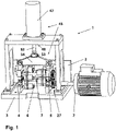
- FIG. 12 also shows the model test stand 1 according to the invention in a more basic representation and illustrates the positions of the components relative to one another in a frontal section.
- the drive motor 2 drives a first shaft 6 which is mounted in a first frame 4 .
- the first frame 4 is firmly connected to a frame 3 .
- the drive motor 2 also drives a second shaft 7 , which is mounted in a second frame 5 , via a gear 27 .
- This second frame 5 is movably connected to the frame 3 in such a way that the center distance between the two shafts 6 and 7 can be changed in such a way that the axes of rotation of the two shafts 6 and 7 remain parallel.
- each of the two shafts 6 and 7 carries two disk-shaped test specimens.
- the disk-shaped test bodies 11 and 13 are seated on the first shaft 6 and the disk-shaped test bodies 12 and 14 are seated on the second shaft 7.
- 3 shows the axial position of the disk-shaped test specimen 11 to 14 on both shafts 6 and 7.
- the first disk-shaped test body 11 touches on the first shaft 6 and the second disk-shaped test body 12 on the second shaft 7.
- the third disk-shaped test body touches 13 on the first shaft 6 and the fourth disk-shaped test body 14 on the second shaft 7.
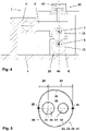
- the loading device 45 which is described in many details in 1 can be seen creates a force between the two shafts 6 and 7 on a line of action 46 between the two shaft centers which is in 4 you can see.
- a servo-hydraulic or electromagnetic actuator 47 is supported on the frame 3 and presses a push rod 52 via a load cell 53 against a traverse 54 which is connected to the second frame 5 via joints.
- How out 3 shows that the loading device is located in a third front section plane 10 exactly in the middle between the first front section plane 8 and the second front section plane 9. This ensures that the force from the loading device 45 is distributed evenly to the two disk-shaped test specimens 11 and 13 or 12 and 14 of each Wave 6 and 7 split.
- a lifting mechanism 48 which is not detailed here, can also act between the first frame 4 and the second frame 5 in order to bring the disk-shaped test bodies out of contact briefly and for a few tenths of a millimeter. As a result, the first contact of two meshing tooth flanks can be reproduced even more realistically.
- the loading device 45 shows a section in the first end section plane 8 through the model test stand 1 in a likewise more basic illustration. It is easy to see here how the loading device 45 generates a pressure load between the first frame 4 on the frame 3 and the second frame 5, whose line of action 46 crosses the center lines of both waves 6 and 7.
- the loading device 45 should preferably have a servo-hydraulic actuator or an electromagnetic actuator 47, both of which are suitable for applying dynamic load collectives.
- 4 It is easy to see that the first disk-shaped test body 11 and the second disk-shaped test body 12 have a non-round outer contour 20 with a constantly changing curvature.
- Such an outer contour 20 has a first Partial profile 21 and a second partial profile 22, which lie on opposite sides of a line of symmetry 18 and merge into one another by mirroring on this line of symmetry 18.
- the disk-shaped test bodies 11 to 14 each have a center 15 of the test body, which lies on the symmetry line 18 with a smallest contour distance 23 to an intersection of the symmetry line 18 with the non-round outer contour 20 in a first contour point 25 and a greatest contour distance 24 to the other intersection of the Line of symmetry 18 with the non-round outer contour 20 in the second contour point 26.
- each disk-shaped test body 11 to 14 has a first hole 16, the center of which is in the center of the test body 15, and that the disk-shaped test body has a second hole 17, the center of which is preferably on the line of symmetry 18 between the center of the test body 15 and the second contour point 26 with the largest contour distance 24 is located.
- each shaft 6 and 7 has a middle part 32 with it on both sides subsequent centering shoulders for the test specimens 34 and subsequent centering shoulders for clamping pieces 35.
- the centering shoulders for the test specimens 34 pierce the first front section plane 8 on one side of the respective middle part 32 and the second front section plane 9 on the other side of the middle part 32.
- the center parts 32 At the two ends of the Center part 32 toward the centering shoulders for the test bodies 34 , the center parts 32 have radial stop pins with shaped elements 33 .
- the two radial stop pins with shaped elements 33 of a central part 32 point in opposite directions.
- FIG. 6 also shows how the disk-shaped test bodies 11 and 13 are centered and aligned on the shaft 6 and the disk-shaped test bodies 12 and 14 on the shaft 7 .
- the disk-shaped test bodies 11 [12] and 13 [14] are centered by means of their first bores 16 on the centering shoulders for test bodies 34 on the shaft 6 [7].
- the disk-shaped test bodies 11 [12] and 13 [14] on the shaft 6 [7] become corresponding bores in the radial stop pins with shaped elements 33 aligned.
- Clamping pieces 36 are then placed on the centering shoulders for clamping pieces 35 and braced with the radial stop pin 33 via screw connections for test specimens 37 .
- the alignment system 31 consists in the possibility of rotating the gear sleeves 43 on the gear-side shaft ends 40 and expansion screw connections for the shafts 44, with which an axial non-positive connection between the sleeves 42 on the free shaft end 38 and the gear sleeves 43 on the gear-side shaft end 40 via the shafts 6 and 7 and possibly further sleeves are produced.
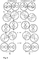
- the 8 finally shows the disc-shaped test specimens 11 to 14 on both shafts 6 and 7 in both front sectional planes 8 and 9.
- the disc-shaped test specimens 13 and 14 in the second front sectional plane 9 are rotated by 180° compared to the disc-shaped test specimens 11 and 12 in the first front sectional plane 8.
- the shaft 6 rotates counterclockwise and the shaft 7 clockwise.
- the non-round outer contour 20 of all test bodies can be designed exactly in such a way that the two test bodies 11 and 12 touch in all relative positions with a constant center distance 51.
Landscapes
- Physics & Mathematics (AREA)
- Health & Medical Sciences (AREA)
- Life Sciences & Earth Sciences (AREA)
- Chemical & Material Sciences (AREA)
- Analytical Chemistry (AREA)
- Biochemistry (AREA)
- General Health & Medical Sciences (AREA)
- General Physics & Mathematics (AREA)
- Immunology (AREA)
- Pathology (AREA)
- Engineering & Computer Science (AREA)
- Automation & Control Theory (AREA)
- Testing Of Devices, Machine Parts, Or Other Structures Thereof (AREA)
Claims (10)
- Modèle de banc d'essai (1) pour les tests tribologiques sur des spécimens en forme de disque (11, 12) avec un premier arbre (6) qui est monté dans un premier cadre (4) et entraîné par un moteur (2) et qui porte un premier spécimen en forme de disque (11) dans une première section transversale (8) et avec un deuxième arbre (7) qui est alimenté dans un deuxième cadre (5) parallèle au premier arbre (6) et qui est entraîné par le premier arbre (6) via une boîte de vitesses (27) et qui porte un deuxième spécimen en forme de disque (12) dans la première section transversale (8), avec le premier cadre (4) solidement fixé dans un châssis (3) et le deuxième cadre (5) monté de manière mobile dans le châssis (3), et avec un dispositif de charge (45) entre la première cadre (4) et la deuxième cadre (5),
caractérisé en ce que
le premier spécimen en forme de disque (11) et le deuxième spécimen en forme de disque (12) ont chacun un contour extérieur non circulaire (20) avec une courbure variable en permanence dans la première section transversale (8) avec un premier profil partiel (21) et un profil partiel second (22) qui sont situés sur les côtés opposés d'une ligne de symétrie (18) et fusionnent l'un dans l'autre en se reflétant à cette ligne de symétrie (18), dans laquelle les deux spécimens en forme de disque (11, 12) ont un centre (15) qui est situé sur la ligne de symétrie (18) avec une plus petite distance de contour (23) à un point d'intersection de la ligne de symétrie (18) avec le contour extérieur non circulaire (20) dans un premier point de contour (25) et avec une plus grande distance de contour (24) à l'autre point d'intersection de la ligne de symétrie (18) avec le contour extérieur non circulaire (20) dans un deuxième point de contour (26). - Modèle de banc d'essai (1) selon la revendication 1,
caractérisé en ce
que les premier et deuxième spécimens en forme de disque (11, 12) ont chacun un premier trou de forage (16), qui est situé au centre (15), et que les spécimens en forme de disque (11, 12) ont chacun un deuxième trou de forage(17), dont le centre est de préférence situé sur la ligne de symétrie (18) entre le centre (15) et le deuxième point de contour (26) avec la plus grande distance de contour (24), et que les spécimens en forme de disque (11, 12) sont centrées au moyen du premier trous de forage (16) sur les sections de centrage (34) sur les arbres (6, 7) et que les spécimen en forme de disque (11, 12) sont alignées sur les arbres (6, 7) au moyen des deuxièmes trous (17) et d'autres touches (19). - Modèle de banc d'essai (1) selon l'une des revendications 1 à 2,
caractérisé en ce
que la boîte de vitesses (27) relie le premier arbre (6) et le deuxième arbre (7) par un étage d'engrenages droits (28) avec un rapport constant de i=-1 entre une première roue dentée (29) montée sur le premier arbre (6) et une seconde roue dentée (30) montée sur le deuxième arbre (7), et que la boîte de vitesses (27) comprend un système d'alignement (31) pour un réglage de la position angulaire de rotation entre le premier arbre (6) et le deuxième arbre (7). - Modèle de banc d'essai (1) selon l'une des revendications 1 à 3,
caractérisé en ce
que les deux arbres (6, 7) avec les spécimens en forme de disque (11, 12) alignées sur ceux-ci sont alignés l'un par rapport à l'autre dans le sens de rotation via la boîte de vitesses (27) et de son système d'alignement (31) et sont chargés l'un contre l'autre par le dispositif de charge (45) de telle sorte que, dans une première position de rotation des deux spécimens en forme de disque (11, 12), le premier point de contour (25) du premier spécimen en forme de disque (11) et le deuxième point de contour (26) de la deuxième spécimen en forme de disque (12) entrent en contact, et que dans une position de rotation décalée de 180° des deux spécimens en forme de disque (11, 12), le deuxième point de contour (26) du premier spécimen en forme de disque (11) et le premier point de contour (25) du deuxième spécimen en forme de disque (12) entrent en contact. - Modèle de banc d'essai (1) selon l'une des revendications 1 à 4,
caractérisé en ce
que le premier profil partiel (21) et le deuxième profil partiel (22) des contours d'outer non circulaires (20) des deux spécimens en forme de disque (11, 12) sont conçus de telle manière entre les premiers points de contour (25) et t e deuxième point de contour (26) que dans chaque position de torsion du premier arbre (6) et du deuxième arbre (7) une ligne normale de contact commune (49) des contours non circulaires en contact (20) traverse un point de pas (50), situé exactement au milieu d'une distance centrale constante (51) entre les centres fixes (15) des deux spécimens en forme de disque (11, 12). - Modèle de banc d'essai (1) selon l'une des revendications 1 à 5,
caractérisé en ce
qu'un troisième spécimen en forme de disque (13) avec un contour extérieur non circulaire identique (20) à celui du premier spécimen en forme de disque (11) se trouve sur le premier arbre (6) dans une deuxième section transversale (9), en fait coaxialement aligné avec son premier trou (16) au premier trou (16) du premier spécimen en forme de disque (11), mais décalé de 180° par rapport au premier spécimen en forme de disque (11), et qu'un quatrième spécimen en forme de disque (14) avec un contour extérieur non circulaire identique (20) à celui du deuxième spécimen en forme de disque (12) se trouve sur le deuxième arbre (7) également dans la deuxième section transversale (9), également aligné coaxialement avec son premier trou (16) au premier trou (16) du deuxième spécimen en forme de disque (12), mais également décalé de 180° par rapport au deuxième spécimen en forme de disque (12) . - Modèle de banc d'essai (1) selon l'une des revendications 1 à 6,
caractérisé en ce
que le premier arbre (6) et le deuxième arbre (7) ont chacun une partie centrale (32) entre une extrémité d'arbre libre (38) et une extrémité d'arbre côté engrenage (40) ayant des sections de centrage adjacentes pour les éprouvettes d'essai (34) pour centrer les spécimens en forme de disque (11, 12, 13, 14) sur leurs premiers trous (16) et les sections de centrage suivantes pour les pièces de serrage (35) et que les deux parties centrale (32) des arbres (6, 7) ont des bouchons radiaux avec des éléments façonnés (33) pour aligner les spécimens en forme de disque (11, 12, 13, 14) au moyen de leurs deuxièmes trous (17) et d'autres clés (19) et que les spécimens en forme de disque (11, 12, 13, 14 ) sont serrés par des pièces de serrage (36) et des raccords vissés pour éprouvettes (37) contre les bouchons radiaux avec des éléments façonnés (33). - Modèle de banc d'essai (1) selon l'une des revendications 1 à 7,
caractérisé en ce
que le dispositif de chargement (45) est situé dans une troisième section transversale (10), qui est située au milieu entre la première section transversale (8) et la deuxième section transversale (9), et que la ligne d'action (46) de la charge le dispositif (45) coupe les lignes centrales des deux arbres (6, 7). - Modèle de banc d'essai (1) selon l'une des revendications 1 à 8,
caractérisé en
que le dispositif de charge (45) contient un actionneur servo-hydraulique ou électromagnétique (47), qui peut faire passer la force de charge de zéro à une valeur maximale et la ramener à zéro à chaque demi-rotation d'arbre. - Modèle de banc d'essai (1) selon l'une des revendications 1 à 9,
caractérisé en
que le dispositif de charge (45) contient un mécanisme de levage (48), qui peut soulever le deuxième cadre (5) du premier cadre (4) de quelques dixièmes de millimètre tous les 180° de rotation de l'arbre.
Applications Claiming Priority (2)
| Application Number | Priority Date | Filing Date | Title |
|---|---|---|---|
| DE102016015529.9A DE102016015529B4 (de) | 2016-12-24 | 2016-12-24 | Modellprüfstand |
| PCT/EP2017/083542 WO2018114950A1 (fr) | 2016-12-24 | 2017-12-19 | Banc d'essai pour modèles pour des essais tribologiques sur des corps d'essai non circulaires, en forme de disque |
Publications (2)
| Publication Number | Publication Date |
|---|---|
| EP3559632A1 EP3559632A1 (fr) | 2019-10-30 |
| EP3559632B1 true EP3559632B1 (fr) | 2022-07-06 |
Family
ID=61005771
Family Applications (1)
| Application Number | Title | Priority Date | Filing Date |
|---|---|---|---|
| EP17832218.6A Active EP3559632B1 (fr) | 2016-12-24 | 2017-12-19 | Banc d'essai pour modèles pour des essais tribologiques sur des corps d'essai non circulaires, en forme de disque |
Country Status (3)
| Country | Link |
|---|---|
| EP (1) | EP3559632B1 (fr) |
| DE (1) | DE102016015529B4 (fr) |
| WO (1) | WO2018114950A1 (fr) |
Families Citing this family (2)
| Publication number | Priority date | Publication date | Assignee | Title |
|---|---|---|---|---|
| CN110261103B (zh) * | 2019-07-01 | 2020-12-29 | 重庆大学 | 一种基于数控系统的可变中心距齿轮接触疲劳试验台 |
| CN111257149A (zh) * | 2020-03-25 | 2020-06-09 | 齐鲁工业大学 | 一种冲蚀环境下材料疲劳性能试验装置及测试方法 |
Family Cites Families (5)
| Publication number | Priority date | Publication date | Assignee | Title |
|---|---|---|---|---|
| DE3140661C1 (de) | 1981-10-13 | 1983-02-03 | Lubricants International AG, 9490 Vaduz | Vorrichtung zum Simulieren der Beanspruchung von zwei gegeneinander gleitenden und sich aufeinander abwaelzenden Koerpern,insbesondere von Zahnraedern |
| DE3604653A1 (de) | 1986-02-14 | 1987-08-27 | Optimol Instr Gmbh | Vorrichtung zur untersuchung des verhaltens kontraformer kontakte |
| GB2194060A (en) | 1986-07-22 | 1988-02-24 | Plint & Partners Ltd | Lubricant testing apparatus |
| US6227032B1 (en) * | 1998-12-29 | 2001-05-08 | Ford Global Technologies, Inc. | Surface durability roll tester |
| GB9924032D0 (en) * | 1999-10-11 | 1999-12-15 | Torotrak Dev Ltd | Test apparatus |
-
2016
- 2016-12-24 DE DE102016015529.9A patent/DE102016015529B4/de active Active
-
2017
- 2017-12-19 WO PCT/EP2017/083542 patent/WO2018114950A1/fr not_active Ceased
- 2017-12-19 EP EP17832218.6A patent/EP3559632B1/fr active Active
Also Published As
| Publication number | Publication date |
|---|---|
| DE102016015529A1 (de) | 2018-06-28 |
| EP3559632A1 (fr) | 2019-10-30 |
| WO2018114950A1 (fr) | 2018-06-28 |
| DE102016015529B4 (de) | 2018-09-27 |
Similar Documents
| Publication | Publication Date | Title |
|---|---|---|
| DE102010017456B4 (de) | Belastungsvorrichtung, Prüfstand mit einer derartigen Belastungsvorrichtung, Prüfanordnung und Prüfverfahren | |
| EP1266154B1 (fr) | Procede permettant d'assembler une unite a roue planetaire dans une position precise | |
| EP1998930B1 (fr) | Dispositif de positionnement | |
| DE3916314C2 (fr) | ||
| EP3771519A1 (fr) | Dispositif de vissage pourvu de moyen de détection intégré | |
| EP3559632B1 (fr) | Banc d'essai pour modèles pour des essais tribologiques sur des corps d'essai non circulaires, en forme de disque | |
| DE10330947A1 (de) | Kreuzfederelement | |
| DE3725872C2 (fr) | ||
| DE3604653C2 (fr) | ||
| DE102008013983B3 (de) | Verfahren zur Einstellung einer Zahnflankenposition eines Zahnrads, das mit einer zweifach schrägverzahnten Ritzelwelle kraftschlüssig verbunden ist | |
| DE4325403C2 (de) | Verspannungsprüfstand | |
| EP3488971A1 (fr) | Dispositif de pivotement électrique | |
| DE102011080564A1 (de) | Reibradgetriebe und Verspannungsprüfeinrichtung für Zahnräder | |
| DE102005044903B4 (de) | Vorrichtung und Verfahren zur Belastungsprüfung einer Radsatzwelle | |
| DE2544254A1 (de) | Verfahren und auswuchtmaschine zum auswuchten von zusammengesetzten werkstuecken, insbesondere gelenkwellen | |
| DE2461773C2 (de) | Stellgerät als einbaufähige Baueinheit mit Spindelmuttertrieb | |
| DE102014207134A1 (de) | Differenzialgetriebe mit Beschränkungsmechanismus | |
| DE102009015689B4 (de) | Vorrichtung und Verfahren zur Prüfung der Betriebsfestigkeit einer Exzenterwelle | |
| DE19805756C1 (de) | Vorrichtung zum Erproben eines Druckkamms | |
| DE3140661C1 (de) | Vorrichtung zum Simulieren der Beanspruchung von zwei gegeneinander gleitenden und sich aufeinander abwaelzenden Koerpern,insbesondere von Zahnraedern | |
| DE102006062201B4 (de) | Walzgerüst zum Walzen von langgestrecktem Gut | |
| WO2004033937A1 (fr) | Dispositif de montage pour des engrenages et procede pour regler le jeu de flancs des dents d'un appariement de roues dentees d'engrenage | |
| DE69902220T2 (de) | Rollervorrichtung zum Testen der Beständigkeit von Oberflächen | |
| DE102010045876A1 (de) | Antriebseinheit mit wenigstens einem Antrieb und mit mindestens einem Planetendifferenzial | |
| DE102021122665A1 (de) | Antriebsflansch und Auswuchtmaschine mit einem solchen |
Legal Events
| Date | Code | Title | Description |
|---|---|---|---|
| STAA | Information on the status of an ep patent application or granted ep patent |
Free format text: STATUS: UNKNOWN |
|
| STAA | Information on the status of an ep patent application or granted ep patent |
Free format text: STATUS: THE INTERNATIONAL PUBLICATION HAS BEEN MADE |
|
| PUAI | Public reference made under article 153(3) epc to a published international application that has entered the european phase |
Free format text: ORIGINAL CODE: 0009012 |
|
| STAA | Information on the status of an ep patent application or granted ep patent |
Free format text: STATUS: REQUEST FOR EXAMINATION WAS MADE |
|
| 17P | Request for examination filed |
Effective date: 20190724 |
|
| AK | Designated contracting states |
Kind code of ref document: A1 Designated state(s): AL AT BE BG CH CY CZ DE DK EE ES FI FR GB GR HR HU IE IS IT LI LT LU LV MC MK MT NL NO PL PT RO RS SE SI SK SM TR |
|
| AX | Request for extension of the european patent |
Extension state: BA ME |
|
| RIN1 | Information on inventor provided before grant (corrected) |
Inventor name: WEIBRING, MAX Inventor name: TENBERGE, PETER Inventor name: GONDECKI, LEONARD |
|
| DAV | Request for validation of the european patent (deleted) | ||
| DAX | Request for extension of the european patent (deleted) | ||
| GRAP | Despatch of communication of intention to grant a patent |
Free format text: ORIGINAL CODE: EPIDOSNIGR1 |
|
| STAA | Information on the status of an ep patent application or granted ep patent |
Free format text: STATUS: GRANT OF PATENT IS INTENDED |
|
| INTG | Intention to grant announced |
Effective date: 20220210 |
|
| GRAS | Grant fee paid |
Free format text: ORIGINAL CODE: EPIDOSNIGR3 |
|
| GRAA | (expected) grant |
Free format text: ORIGINAL CODE: 0009210 |
|
| STAA | Information on the status of an ep patent application or granted ep patent |
Free format text: STATUS: THE PATENT HAS BEEN GRANTED |
|
| AK | Designated contracting states |
Kind code of ref document: B1 Designated state(s): AL AT BE BG CH CY CZ DE DK EE ES FI FR GB GR HR HU IE IS IT LI LT LU LV MC MK MT NL NO PL PT RO RS SE SI SK SM TR |
|
| REG | Reference to a national code |
Ref country code: AT Ref legal event code: REF Ref document number: 1503192 Country of ref document: AT Kind code of ref document: T Effective date: 20220715 Ref country code: CH Ref legal event code: EP |
|
| REG | Reference to a national code |
Ref country code: DE Ref legal event code: R096 Ref document number: 502017013444 Country of ref document: DE |
|
| REG | Reference to a national code |
Ref country code: IE Ref legal event code: FG4D Free format text: LANGUAGE OF EP DOCUMENT: GERMAN |
|
| REG | Reference to a national code |
Ref country code: LT Ref legal event code: MG9D |
|
| REG | Reference to a national code |
Ref country code: NL Ref legal event code: MP Effective date: 20220706 |
|
| PG25 | Lapsed in a contracting state [announced via postgrant information from national office to epo] |
Ref country code: SE Free format text: LAPSE BECAUSE OF FAILURE TO SUBMIT A TRANSLATION OF THE DESCRIPTION OR TO PAY THE FEE WITHIN THE PRESCRIBED TIME-LIMIT Effective date: 20220706 Ref country code: RS Free format text: LAPSE BECAUSE OF FAILURE TO SUBMIT A TRANSLATION OF THE DESCRIPTION OR TO PAY THE FEE WITHIN THE PRESCRIBED TIME-LIMIT Effective date: 20220706 Ref country code: PT Free format text: LAPSE BECAUSE OF FAILURE TO SUBMIT A TRANSLATION OF THE DESCRIPTION OR TO PAY THE FEE WITHIN THE PRESCRIBED TIME-LIMIT Effective date: 20221107 Ref country code: NO Free format text: LAPSE BECAUSE OF FAILURE TO SUBMIT A TRANSLATION OF THE DESCRIPTION OR TO PAY THE FEE WITHIN THE PRESCRIBED TIME-LIMIT Effective date: 20221006 Ref country code: NL Free format text: LAPSE BECAUSE OF FAILURE TO SUBMIT A TRANSLATION OF THE DESCRIPTION OR TO PAY THE FEE WITHIN THE PRESCRIBED TIME-LIMIT Effective date: 20220706 Ref country code: LV Free format text: LAPSE BECAUSE OF FAILURE TO SUBMIT A TRANSLATION OF THE DESCRIPTION OR TO PAY THE FEE WITHIN THE PRESCRIBED TIME-LIMIT Effective date: 20220706 Ref country code: LT Free format text: LAPSE BECAUSE OF FAILURE TO SUBMIT A TRANSLATION OF THE DESCRIPTION OR TO PAY THE FEE WITHIN THE PRESCRIBED TIME-LIMIT Effective date: 20220706 Ref country code: FI Free format text: LAPSE BECAUSE OF FAILURE TO SUBMIT A TRANSLATION OF THE DESCRIPTION OR TO PAY THE FEE WITHIN THE PRESCRIBED TIME-LIMIT Effective date: 20220706 Ref country code: ES Free format text: LAPSE BECAUSE OF FAILURE TO SUBMIT A TRANSLATION OF THE DESCRIPTION OR TO PAY THE FEE WITHIN THE PRESCRIBED TIME-LIMIT Effective date: 20220706 |
|
| PG25 | Lapsed in a contracting state [announced via postgrant information from national office to epo] |
Ref country code: PL Free format text: LAPSE BECAUSE OF FAILURE TO SUBMIT A TRANSLATION OF THE DESCRIPTION OR TO PAY THE FEE WITHIN THE PRESCRIBED TIME-LIMIT Effective date: 20220706 Ref country code: IS Free format text: LAPSE BECAUSE OF FAILURE TO SUBMIT A TRANSLATION OF THE DESCRIPTION OR TO PAY THE FEE WITHIN THE PRESCRIBED TIME-LIMIT Effective date: 20221106 Ref country code: HR Free format text: LAPSE BECAUSE OF FAILURE TO SUBMIT A TRANSLATION OF THE DESCRIPTION OR TO PAY THE FEE WITHIN THE PRESCRIBED TIME-LIMIT Effective date: 20220706 Ref country code: GR Free format text: LAPSE BECAUSE OF FAILURE TO SUBMIT A TRANSLATION OF THE DESCRIPTION OR TO PAY THE FEE WITHIN THE PRESCRIBED TIME-LIMIT Effective date: 20221007 |
|
| REG | Reference to a national code |
Ref country code: DE Ref legal event code: R097 Ref document number: 502017013444 Country of ref document: DE |
|
| PG25 | Lapsed in a contracting state [announced via postgrant information from national office to epo] |
Ref country code: SM Free format text: LAPSE BECAUSE OF FAILURE TO SUBMIT A TRANSLATION OF THE DESCRIPTION OR TO PAY THE FEE WITHIN THE PRESCRIBED TIME-LIMIT Effective date: 20220706 Ref country code: RO Free format text: LAPSE BECAUSE OF FAILURE TO SUBMIT A TRANSLATION OF THE DESCRIPTION OR TO PAY THE FEE WITHIN THE PRESCRIBED TIME-LIMIT Effective date: 20220706 Ref country code: DK Free format text: LAPSE BECAUSE OF FAILURE TO SUBMIT A TRANSLATION OF THE DESCRIPTION OR TO PAY THE FEE WITHIN THE PRESCRIBED TIME-LIMIT Effective date: 20220706 Ref country code: CZ Free format text: LAPSE BECAUSE OF FAILURE TO SUBMIT A TRANSLATION OF THE DESCRIPTION OR TO PAY THE FEE WITHIN THE PRESCRIBED TIME-LIMIT Effective date: 20220706 |
|
| PLBE | No opposition filed within time limit |
Free format text: ORIGINAL CODE: 0009261 |
|
| STAA | Information on the status of an ep patent application or granted ep patent |
Free format text: STATUS: NO OPPOSITION FILED WITHIN TIME LIMIT |
|
| PG25 | Lapsed in a contracting state [announced via postgrant information from national office to epo] |
Ref country code: SK Free format text: LAPSE BECAUSE OF FAILURE TO SUBMIT A TRANSLATION OF THE DESCRIPTION OR TO PAY THE FEE WITHIN THE PRESCRIBED TIME-LIMIT Effective date: 20220706 Ref country code: EE Free format text: LAPSE BECAUSE OF FAILURE TO SUBMIT A TRANSLATION OF THE DESCRIPTION OR TO PAY THE FEE WITHIN THE PRESCRIBED TIME-LIMIT Effective date: 20220706 |
|
| 26N | No opposition filed |
Effective date: 20230411 |
|
| PG25 | Lapsed in a contracting state [announced via postgrant information from national office to epo] |
Ref country code: AL Free format text: LAPSE BECAUSE OF FAILURE TO SUBMIT A TRANSLATION OF THE DESCRIPTION OR TO PAY THE FEE WITHIN THE PRESCRIBED TIME-LIMIT Effective date: 20220706 |
|
| REG | Reference to a national code |
Ref country code: BE Ref legal event code: MM Effective date: 20221231 |
|
| PG25 | Lapsed in a contracting state [announced via postgrant information from national office to epo] |
Ref country code: SI Free format text: LAPSE BECAUSE OF FAILURE TO SUBMIT A TRANSLATION OF THE DESCRIPTION OR TO PAY THE FEE WITHIN THE PRESCRIBED TIME-LIMIT Effective date: 20220706 Ref country code: LU Free format text: LAPSE BECAUSE OF NON-PAYMENT OF DUE FEES Effective date: 20221219 |
|
| PG25 | Lapsed in a contracting state [announced via postgrant information from national office to epo] |
Ref country code: IE Free format text: LAPSE BECAUSE OF NON-PAYMENT OF DUE FEES Effective date: 20221219 |
|
| PG25 | Lapsed in a contracting state [announced via postgrant information from national office to epo] |
Ref country code: BE Free format text: LAPSE BECAUSE OF NON-PAYMENT OF DUE FEES Effective date: 20221231 |
|
| PG25 | Lapsed in a contracting state [announced via postgrant information from national office to epo] |
Ref country code: IT Free format text: LAPSE BECAUSE OF FAILURE TO SUBMIT A TRANSLATION OF THE DESCRIPTION OR TO PAY THE FEE WITHIN THE PRESCRIBED TIME-LIMIT Effective date: 20220706 |
|
| REG | Reference to a national code |
Ref country code: AT Ref legal event code: MM01 Ref document number: 1503192 Country of ref document: AT Kind code of ref document: T Effective date: 20221219 |
|
| PG25 | Lapsed in a contracting state [announced via postgrant information from national office to epo] |
Ref country code: HU Free format text: LAPSE BECAUSE OF FAILURE TO SUBMIT A TRANSLATION OF THE DESCRIPTION OR TO PAY THE FEE WITHIN THE PRESCRIBED TIME-LIMIT; INVALID AB INITIO Effective date: 20171219 |
|
| PG25 | Lapsed in a contracting state [announced via postgrant information from national office to epo] |
Ref country code: AT Free format text: LAPSE BECAUSE OF NON-PAYMENT OF DUE FEES Effective date: 20221219 |
|
| PG25 | Lapsed in a contracting state [announced via postgrant information from national office to epo] |
Ref country code: CY Free format text: LAPSE BECAUSE OF FAILURE TO SUBMIT A TRANSLATION OF THE DESCRIPTION OR TO PAY THE FEE WITHIN THE PRESCRIBED TIME-LIMIT Effective date: 20220706 Ref country code: AT Free format text: LAPSE BECAUSE OF NON-PAYMENT OF DUE FEES Effective date: 20221219 |
|
| PG25 | Lapsed in a contracting state [announced via postgrant information from national office to epo] |
Ref country code: MK Free format text: LAPSE BECAUSE OF FAILURE TO SUBMIT A TRANSLATION OF THE DESCRIPTION OR TO PAY THE FEE WITHIN THE PRESCRIBED TIME-LIMIT Effective date: 20220706 |
|
| PG25 | Lapsed in a contracting state [announced via postgrant information from national office to epo] |
Ref country code: MC Free format text: LAPSE BECAUSE OF FAILURE TO SUBMIT A TRANSLATION OF THE DESCRIPTION OR TO PAY THE FEE WITHIN THE PRESCRIBED TIME-LIMIT Effective date: 20220706 |
|
| PG25 | Lapsed in a contracting state [announced via postgrant information from national office to epo] |
Ref country code: MC Free format text: LAPSE BECAUSE OF FAILURE TO SUBMIT A TRANSLATION OF THE DESCRIPTION OR TO PAY THE FEE WITHIN THE PRESCRIBED TIME-LIMIT Effective date: 20220706 |
|
| PG25 | Lapsed in a contracting state [announced via postgrant information from national office to epo] |
Ref country code: BG Free format text: LAPSE BECAUSE OF FAILURE TO SUBMIT A TRANSLATION OF THE DESCRIPTION OR TO PAY THE FEE WITHIN THE PRESCRIBED TIME-LIMIT Effective date: 20220706 |
|
| PG25 | Lapsed in a contracting state [announced via postgrant information from national office to epo] |
Ref country code: MT Free format text: LAPSE BECAUSE OF FAILURE TO SUBMIT A TRANSLATION OF THE DESCRIPTION OR TO PAY THE FEE WITHIN THE PRESCRIBED TIME-LIMIT Effective date: 20220706 |
|
| PGFP | Annual fee paid to national office [announced via postgrant information from national office to epo] |
Ref country code: DE Payment date: 20241231 Year of fee payment: 8 |
|
| PGFP | Annual fee paid to national office [announced via postgrant information from national office to epo] |
Ref country code: GB Payment date: 20241218 Year of fee payment: 8 |
|
| PGFP | Annual fee paid to national office [announced via postgrant information from national office to epo] |
Ref country code: FR Payment date: 20241217 Year of fee payment: 8 |
|
| PGFP | Annual fee paid to national office [announced via postgrant information from national office to epo] |
Ref country code: CH Payment date: 20250101 Year of fee payment: 8 |
|
| PG25 | Lapsed in a contracting state [announced via postgrant information from national office to epo] |
Ref country code: TR Free format text: LAPSE BECAUSE OF FAILURE TO SUBMIT A TRANSLATION OF THE DESCRIPTION OR TO PAY THE FEE WITHIN THE PRESCRIBED TIME-LIMIT Effective date: 20220706 |