EP3559638B1 - Vorrichtung zur erfassung von emittiertem fluoreszierendem licht von partikeln in einem medium - Google Patents
Vorrichtung zur erfassung von emittiertem fluoreszierendem licht von partikeln in einem medium Download PDFInfo
- Publication number
- EP3559638B1 EP3559638B1 EP17817715.0A EP17817715A EP3559638B1 EP 3559638 B1 EP3559638 B1 EP 3559638B1 EP 17817715 A EP17817715 A EP 17817715A EP 3559638 B1 EP3559638 B1 EP 3559638B1
- Authority
- EP
- European Patent Office
- Prior art keywords
- waveguide
- fluorescent light
- light
- particles
- coupler
- Prior art date
- Legal status (The legal status is an assumption and is not a legal conclusion. Google has not performed a legal analysis and makes no representation as to the accuracy of the status listed.)
- Active
Links
Images



Classifications
-
- G—PHYSICS
- G01—MEASURING; TESTING
- G01N—INVESTIGATING OR ANALYSING MATERIALS BY DETERMINING THEIR CHEMICAL OR PHYSICAL PROPERTIES
- G01N21/00—Investigating or analysing materials by the use of optical means, i.e. using sub-millimetre waves, infrared, visible or ultraviolet light
- G01N21/62—Systems in which the material investigated is excited whereby it emits light or causes a change in wavelength of the incident light
- G01N21/63—Systems in which the material investigated is excited whereby it emits light or causes a change in wavelength of the incident light optically excited
- G01N21/64—Fluorescence; Phosphorescence
- G01N21/645—Specially adapted constructive features of fluorimeters
- G01N21/648—Specially adapted constructive features of fluorimeters using evanescent coupling or surface plasmon coupling for the excitation of fluorescence
-
- G—PHYSICS
- G01—MEASURING; TESTING
- G01N—INVESTIGATING OR ANALYSING MATERIALS BY DETERMINING THEIR CHEMICAL OR PHYSICAL PROPERTIES
- G01N15/00—Investigating characteristics of particles; Investigating permeability, pore-volume or surface-area of porous materials
- G01N15/06—Investigating concentration of particle suspensions
-
- G—PHYSICS
- G02—OPTICS
- G02B—OPTICAL ELEMENTS, SYSTEMS OR APPARATUS
- G02B6/00—Light guides; Structural details of arrangements comprising light guides and other optical elements, e.g. couplings
- G02B6/10—Light guides; Structural details of arrangements comprising light guides and other optical elements, e.g. couplings of the optical waveguide type
- G02B6/12—Light guides; Structural details of arrangements comprising light guides and other optical elements, e.g. couplings of the optical waveguide type of the integrated circuit kind
- G02B6/12004—Combinations of two or more optical elements
-
- G—PHYSICS
- G02—OPTICS
- G02B—OPTICAL ELEMENTS, SYSTEMS OR APPARATUS
- G02B6/00—Light guides; Structural details of arrangements comprising light guides and other optical elements, e.g. couplings
- G02B6/10—Light guides; Structural details of arrangements comprising light guides and other optical elements, e.g. couplings of the optical waveguide type
- G02B6/12—Light guides; Structural details of arrangements comprising light guides and other optical elements, e.g. couplings of the optical waveguide type of the integrated circuit kind
- G02B6/12007—Light guides; Structural details of arrangements comprising light guides and other optical elements, e.g. couplings of the optical waveguide type of the integrated circuit kind forming wavelength selective elements, e.g. multiplexer, demultiplexer
-
- G—PHYSICS
- G02—OPTICS
- G02B—OPTICAL ELEMENTS, SYSTEMS OR APPARATUS
- G02B6/00—Light guides; Structural details of arrangements comprising light guides and other optical elements, e.g. couplings
- G02B6/10—Light guides; Structural details of arrangements comprising light guides and other optical elements, e.g. couplings of the optical waveguide type
- G02B6/12—Light guides; Structural details of arrangements comprising light guides and other optical elements, e.g. couplings of the optical waveguide type of the integrated circuit kind
- G02B6/122—Basic optical elements, e.g. light-guiding paths
- G02B6/125—Bends, branchings or intersections
-
- G—PHYSICS
- G02—OPTICS
- G02B—OPTICAL ELEMENTS, SYSTEMS OR APPARATUS
- G02B6/00—Light guides; Structural details of arrangements comprising light guides and other optical elements, e.g. couplings
- G02B6/24—Coupling light guides
- G02B6/26—Optical coupling means
- G02B6/28—Optical coupling means having data bus means, i.e. plural waveguides interconnected and providing an inherently bidirectional system by mixing and splitting signals
- G02B6/2804—Optical coupling means having data bus means, i.e. plural waveguides interconnected and providing an inherently bidirectional system by mixing and splitting signals forming multipart couplers without wavelength selective elements, e.g. "T" couplers, star couplers
- G02B6/2808—Optical coupling means having data bus means, i.e. plural waveguides interconnected and providing an inherently bidirectional system by mixing and splitting signals forming multipart couplers without wavelength selective elements, e.g. "T" couplers, star couplers using a mixing element which evenly distributes an input signal over a number of outputs
- G02B6/2813—Optical coupling means having data bus means, i.e. plural waveguides interconnected and providing an inherently bidirectional system by mixing and splitting signals forming multipart couplers without wavelength selective elements, e.g. "T" couplers, star couplers using a mixing element which evenly distributes an input signal over a number of outputs based on multimode interference effect, i.e. self-imaging
-
- G—PHYSICS
- G02—OPTICS
- G02B—OPTICAL ELEMENTS, SYSTEMS OR APPARATUS
- G02B6/00—Light guides; Structural details of arrangements comprising light guides and other optical elements, e.g. couplings
- G02B6/24—Coupling light guides
- G02B6/26—Optical coupling means
- G02B6/28—Optical coupling means having data bus means, i.e. plural waveguides interconnected and providing an inherently bidirectional system by mixing and splitting signals
- G02B6/293—Optical coupling means having data bus means, i.e. plural waveguides interconnected and providing an inherently bidirectional system by mixing and splitting signals with wavelength selective means
- G02B6/29331—Optical coupling means having data bus means, i.e. plural waveguides interconnected and providing an inherently bidirectional system by mixing and splitting signals with wavelength selective means operating by evanescent wave coupling
- G02B6/29332—Wavelength selective couplers, i.e. based on evanescent coupling between light guides, e.g. fused fibre couplers with transverse coupling between fibres having different propagation constant wavelength dependency
-
- G—PHYSICS
- G01—MEASURING; TESTING
- G01N—INVESTIGATING OR ANALYSING MATERIALS BY DETERMINING THEIR CHEMICAL OR PHYSICAL PROPERTIES
- G01N15/00—Investigating characteristics of particles; Investigating permeability, pore-volume or surface-area of porous materials
- G01N15/01—Investigating characteristics of particles; Investigating permeability, pore-volume or surface-area of porous materials specially adapted for biological cells, e.g. blood cells
-
- G—PHYSICS
- G01—MEASURING; TESTING
- G01N—INVESTIGATING OR ANALYSING MATERIALS BY DETERMINING THEIR CHEMICAL OR PHYSICAL PROPERTIES
- G01N15/00—Investigating characteristics of particles; Investigating permeability, pore-volume or surface-area of porous materials
- G01N15/06—Investigating concentration of particle suspensions
- G01N15/075—Investigating concentration of particle suspensions by optical means
-
- G—PHYSICS
- G02—OPTICS
- G02B—OPTICAL ELEMENTS, SYSTEMS OR APPARATUS
- G02B6/00—Light guides; Structural details of arrangements comprising light guides and other optical elements, e.g. couplings
- G02B6/10—Light guides; Structural details of arrangements comprising light guides and other optical elements, e.g. couplings of the optical waveguide type
- G02B6/12—Light guides; Structural details of arrangements comprising light guides and other optical elements, e.g. couplings of the optical waveguide type of the integrated circuit kind
- G02B2006/12133—Functions
- G02B2006/12147—Coupler
Definitions
- Exemplary embodiments relate to a method and a device for collecting fluorescent light emitted by particles in a medium.
- a body fluid may be seen as a fluid medium which includes particles, such as molecules, of different types.
- the concentration of the particles may be measured using fluorescence, i.e., the particles may be subject to light which serves to excite the particles, whereby the particles emit fluorescent light which is then collected in order to detect the concentration of particles in the medium.
- Some particles in the body fluids may have a natural capability of emitting fluorescent light. However, if this is not the case, it is also possible to stain the particles by a fluorescent dye, i.e., a dye which binds to the particles and which is capable of emitting fluorescent light.
- Evanescent fields of optical waveguides have been used for excitation of various types of emitting particles, including fluorescent dyes.
- an optical waveguide carrying excitation light may be passed through a medium comprising emitting particles. The same waveguide can then be used to collect the emitted light and guide it to a detector.
- FIG. 1a and Fig. 1b illustrate this principle.
- a medium 102 comprising particles 104 is held by a chamber 106 of a substrate 108.
- a waveguide 110 is arranged at the substrate 108 such that it extends through the chamber 106.
- Excitation light 120 is input to the waveguide 110 at a first end 112, referred to herein as Port 1.
- the excitation light 120 gives rise to an evanescent field around the waveguide 110 which causes excitation of the particles 104.
- the particles 104 emit fluorescent light 122 which is collected by the waveguide 112.
- the collected fluorescent light 124, and the excitation light 120 that remains after the passage through the waveguide are then output at a second end 114 of the waveguide, referred to herein as Port 2, for detection.
- the waveguide 110 thus guides both the excitation light 120 and the collected fluorescent light 124. Since the power of the excitation light 120 typically is orders of magnitude larger than the power of the collected fluorescent light 124, the excitation light needs to be filtered out, e.g., by means of a strong rejection filter, in order to allow the collected emitted light to be detected. Such filters are, due to their size, impractical in many cases, such as when a compact system is desired. There is thus room for improvements.
- US 2013/071850 A1 relates to a scanning sensor system, methods of use and kits for detecting a biologically active analyte.
- the scanning senor system includes a light source, a detector, a substrate comprising a plurality of waveguides and a plurality of optical sensing sites in optical communication with one or more waveguide of the substrate, and at least one adapter configured to couple with the substrate and provide optical communication between the light source, the waveguides of the substrate, and the detector.
- US 2008/212918 A1 relates to a fiber optic sensor device for detecting the presence of a chromophoric compound in a biological fluid.
- the fiber optic sensor device includes at least one fiber optic member having an unclad portion, the fiber optic member having a proximal end and a distal end for transmitting light energy of a determinable wavelength, a light source means for generating light energy of determinable wavelength, said light source means operatively associated with a measuring means such that said light energy passes through said measuring means and said fiber optic member to the biological fluid, and measuring means operatively associated with said fiber optic member and said light source, for measuring the difference between said light energy generated by said light source and light reflected from the distal end of the fiber optic member, wherein the difference is related to the light absorbed by the chromophoric compound and indicative of the concentration of the chromophoric compound present in the biological fluid.
- US 2003/029995 A1 relates to an apparatus and methods for measuring oil flow velocity in a well which utilize fluorescence quenching.
- a marker which quenches the natural fluorescence of crude oil is chosen and injected into the oil flow at a first location.
- the oil flow is subjected to light at a wavelength which will cause oil to naturally fluoresce.
- the fluorescence signal is detected at the second location by a sensing probe.
- the time that it takes for the quenching marker to move from the first location to the second location is measured by sensing a decrease in fluorescence due to the quencher.
- Fluid velocity is determined by dividing the distance between the marker-ejection point and the optical probe position by the time it took the marker to move that distance.
- US 2016/356708 A1 relates to an optical measuring device for measuring a measurement region, the optical device comprising a photonic chip with an interferometer defined on said chip, said interferometer comprising first and second waveguides on said photonic chip and an interference region, wherein the first and second waveguides carry signals from the interference region to the sample region and back to the interference region, the device further comprising a phase adjusting unit configured to vary a phase difference between the signals in the first and second waveguides reflected by the measurement region.
- a device for collecting fluorescent light emitted by particles in a medium as defined in claim 1. Instead of outputting the collected fluorescent light together with the excitation light at an output port of the waveguide, the collected fluorescent light travelling in a direction opposite to the excitation light in the waveguide is coupled out directly into a further waveguide for detection. In this way, there is no need for a rejection filter.
- a method using the device as defined in claim 10.
- a device for collecting fluorescent light emitted by particles in a medium comprising: a substrate having a chamber for holding a medium including particles being capable of emitting fluorescent light, a first waveguide arranged at the substrate and extending into the chamber, wherein the first waveguide is arranged to receive excitation light from a light source and guide the excitation light through the chamber along a first direction of the first waveguide, and to collect fluorescent light emitted by the particles following an excitation of the particles by the excitation light, and a coupler arranged at the first waveguide, wherein the coupler includes a second waveguide arranged to output collected fluorescent light at one of its ends, and wherein the second waveguide is arranged in relation to the first waveguide such that collected fluorescent light travelling in a direction opposite to the first direction is coupled out from the first waveguide directly into the second waveguide.
- the collected fluorescent light is coupled out from the first waveguide directly into the second waveguide. This means that the light goes directly from the first waveguide to the second waveguide without passing via a further waveguide.
- the direct coupling is achieved by overlapping evanescent fields of the first and the second waveguide.
- the coupler relies on an interference pattern of multiple modes supported by the coupler in order to couple out light from the first waveguide directly into the second waveguide.
- excitation light is meant light having a wavelength which is suitable for excitation of the particles in the medium, thereby causing the particles to emit fluorescent light.
- the particles may have a natural capability of emitting fluorescent light.
- the particles are stained by a fluorescent dye, i.e., a dye which binds to the particles and which is capable of emitting fluorescent light.
- the coupler may be arranged at the first waveguide upstream of the chamber in relation to the first direction.
- the coupler is arranged before the chamber, i.e., between the end of the first waveguide where excitation light is received and the chamber.
- the power in the first waveguide is at its highest levels where the first waveguide enters the chamber, meaning that this is where most light is emitted and collected per waveguide length.
- the excitation light and the collected fluorescent light are then attenuated as they propagate along the first waveguide due to waveguide losses and absorption by particles in the medium.
- the coupler is located close to the entrance of the first waveguide into the chamber where most fluorescent light is collected per waveguide length, thus giving rise to an as strong signal as possible.
- the collected fluorescent light will have a short path to travel back to the coupler, meaning that the collected fluorescent light is basically un-attenuated as it reaches the coupler. This location of the coupler in relation to the chamber thus serves to optimize the power of the collected fluorescent light which is coupled out from the first waveguide.
- Fig. 2 shows the collected signal power of the fluorescent light collected at the second end 114, Port 2, of Figs. 1a and 1b as a function of the length of the waveguide 110.
- the solid curve corresponds to a first concentration of particles whereas the dashed curve corresponds to a second, lower, concentration of particles.
- the collected signal power for the solid curve corresponding to the higher concentration, peaks for a lower waveguide length than the dashed curve, corresponding to the lower concentration.
- the optimal waveguide length is thus lower for a higher concentration in relation to the optimal waveguide length for a lower concentration, thus illustrating that there are different optimal waveguide lengths for different concentrations when fluorescent light is collected at Port 2.
- the coupler By arranging the coupler upstream of the chamber, the requirement of having a well-designed optimum length is removed since the power of the collected fluorescent light which reaches the coupler reaches a saturation when the waveguide is long enough.
- the second waveguide may be arranged adjacent to the first waveguide, thereby allowing collected fluorescent light travelling in a direction opposite to the first direction to be coupled out from the first waveguide directly into the second waveguide.
- the coupling is achieved due to overlapping evanescent modes of the first and the second waveguides. This is an easy way of providing a direct coupling from the first to the second waveguide.
- the coupler is a directional coupler.
- a directional coupler is advantageous in that it is relatively insensitive to fabrication variations. Furter, only a low amount of reflection is caused by the directional coupler. In other words, not much of the excitation light guided by the first waveguide in the first direction is scattered back from the first waveguide into the second waveguide.
- a portion of the excitation light is also coupled into the second waveguide.
- the second waveguide is arranged to output collected fluorescent light at a first end, and excitation light, coupled into the second waveguide from the first waveguide, at a second end.
- the coupler may be a wavelength splitter.
- a wavelength splitter is advantageous in that it has no, or at least very low, coupling losses.
- a directional coupler may have a coupling efficiency of 50%, whereas the wavelength splitter has a theoretical coupling efficiency of 100%.
- This wavelength splitter takes advantage of the wavelength difference between the excitation and the collected fluorescent light to optimally couple (up to 100%) each wavelength to the correct output port.
- the wavelength splitter also serves to separate back-scattered excitation light from the collected fluorescent light. In this way, the collected fluorescent light measured at the output of the second waveguide is not contaminated by back-scattered excitation light.
- the coupler may be a multi-mode interference, MMI, coupler.
- MMI multi-mode interference
- An MMI coupler is advantageous in that it is insensitive to fabrication tolerances. Another advantage is that it is broadband, meaning that it has the same or similar properties, such as coupling efficiency, for the waveighths of the excitation light and fluorescent light.
- the coupler may be a wavelength selective MMI.
- a wavelength selective MMI coupler is an MMI coupler which is designed to take advantage of the wavelength difference between the excitation and the collected fluorescent light such that the excitation power goes to one output port, and collected fluorescent power to another output port. In this way, the coupling efficiency is improved compared to a standard MMI coupler.
- the theoretical coupling efficiency for transmission is 100%. However, in practice there are some power losses which are in the order of 2 dB per port. Further, due to the wavelength selective property, backscattered excitation light and collected fluorescent are separated, meaning that the collected fluorescent light measured at the output of the second waveguide is not contaminated by back-scattered excitation light.
- a still further advantage is that, unlike the standard MMI coupler, but similar to the directional coupler, the wavelength selective MMI coupler causes little or no reflection of excitation light, meaning that not much of the excitation light guided by the first waveguide in the first direction is scattered back from the first waveguide into the second waveguide.
- the length of the first waveguide may be selected independently of the concentration of particles capable of emitting fluorescent light in the medium. As further mentioned above, this is possible due to the coupler being arranged upstream of the chamber so as to couple out collected fluorescent light traveling in the direction opposed to the direction of the excitation light.
- the substrate, the first waveguide and the coupler may be arranged on a disposable chip. This is made possible in view of the compactness, and low cost, of the components involved.
- a system for detecting fluorescent light emitted by particles in a medium comprising:
- the system may comprise a disposable part and a non-disposable part, the disposable part being arranged to be connected to the non-disposable part, wherein the light source and the detector are arranged on the non-disposable part, and the device is arranged on the disposable part.
- the coupler is a directional coupler, and the second waveguide is arranged to output collected fluorescent light at a first end, and excitation light, coupled into the second waveguide from the first waveguide, at a second end.
- the detector may further be coupled to the second end of the second waveguide for detecting light being output at said second end, and determining a loss of the directional coupler based on a power of the light detected at the second end of the second waveguide in relation to a power of the excitation light which is input to the first waveguide.
- a diagnostic arrangement comprising the device according to the first aspect or the system of the second aspect.
- a method for detecting fluorescent light emitted by particles in a medium comprising:
- the coupler is a directional coupler, and the method further comprises :
- the second, third, and fourth aspects may generally have the same features and advantages as the first aspect. It is further noted that the inventive concepts relate to all possible combinations of features unless explicitly stated otherwise.
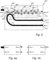
- Fig. 3 illustrates a device 300 for collecting fluorescent light.
- the device 300 comprises a substrate 308 with a chamber 306, a first waveguide 310, a coupler 316 and a second waveguide 317.
- the device 300 may be a photonic integrated circuit.
- the substrate 308 serves as a platform for the photonic integrated circuit.
- the substrate 308 may for example be a silicon chip or quartz chip, covered with an oxide with integrated photonics processed on top.
- a chamber 306. When in use, the chamber 306 holds a medium, such as a body fluid, comprising particles 304.
- the chamber 306, thus serves as a reservoir for holding a medium.
- the chamber 306 may be in the form of a channel, such as micro-fluid channel, through which the medium may flow.
- the particles 304 are capable of emitting fluorescent light, either on their own motion or by means of a fluorescent dye which binds to the particles.
- the first waveguide 310 is arranged at the substrate 308.
- the first waveguide 310 may be integrated in the substrate 308, i.e., on the platform of the photonic integrated circuit.
- the first waveguide 310 extends into the chamber 306.
- the first waveguide 110 extends from a first side of the substrate 308, into and through the chamber 306, and then to a second side of the substrate 308.
- the waveguide 310 does not extend to a second side of the substrate, but rather follows a meandering path through the chamber 306 before ending inside the chamber 306.
- the first waveguide 310 is arranged to receive light 320, referred to herein as excitation light, at a first end 312.
- the first end 312 may also be referred to as Port 1.
- the excitation light 320 may be received from a light source, such as one or more lasers, and may comprise a single or a plurality of distinct wavelengths which are suitable for causing excitation of the particles 304.
- the first waveguide 310 also has a second end 314, referred to herein as Port 2.
- the first waveguide 310 guides the excitation light 320 in a first direction 313, here from left to right, of the first waveguide 310. Since the first waveguide 310 extends into and through the chamber 306, the first waveguide 310 thus guides the excitation light through the chamber 306.
- the surface of the first waveguide 310 is an interface between two dielectrics, implying that the fields of the electromagnetic waves, i.e., the excitation light 320, guided by the first waveguide 310 penetrate outside the first waveguide 310 in the form of an evanescent wave or evanescent field. Due to the existence of the evanescent field, particles 304 which are in the vicinity of the first waveguide 310 may absorb photons of the excitation light 320, and then emit fluorescent light 322.
- the fluorescent light 322 has typically a spectrum of wavelengths corresponding to lower energies than the excitation light 320. A portion of the fluorescent light 322 is then collected by the first waveguide 310 and is guided in both directions of the first waveguide 310. The portion of the fluorescent light 322 that is collected is determined by the mode overlap between the waveguide mode and the fluorescent dipole mode.
- the coupler 316 is arranged at the first waveguide 310.
- the coupler 316 is arranged upstream of the chamber 306 with respect to the first direction 313, i.e., at the portion of the waveguide 310 extending between the first end 312 and the chamber 306.
- the coupler 316 comprises a second waveguide 317.
- the second waveguide 317 is arranged in relation to the first waveguide 310 such that collected fluorescent light 324 travelling in a direction opposite to the first direction 313 is coupled out from the first waveguide 310 directly into the second waveguide 317. This may be accomplished by arranging the second waveguide 317 adjacent to the first waveguide 310. In this way, the evanescent field caused by the collected fluorescent light 324 which propagates in a direction opposite to the first direction 313 in the first waveguide 310 excites a wave in the second waveguide 317, thereby coupling out light from the first waveguide 310 to the second waveguide 317.
- the coupler 316 thus couples out collected fluorescent light 324 from the first waveguide 310 directly to the second waveguide 317 using evanescent wave coupling between the first waveguide 310 and the second waveguide 317.
- the coupler 316 may therefore be referred to as an evanescent coupler.
- the second waveguide 317 is arranged to output, at one of its ends, fluorescent light 326 that has been coupled into the second waveguide 317.
- the second waveguide 317 has a first end 318, also referred to herein as Port 3, at which the collected fluorescent light 326 is output.
- the collected fluorescent light 326 may be directly measured at the first end 318, Port 3, of the second waveguide 317.
- the second waveguide 317 also has a second end 319, which is referred to herein as Port 4.
- the coupler 316 is a directional coupler.
- the directional coupler is associated with a coupling loss.
- the excitation light 320 entering at Port 1 will be split into two portions, wherein one portion is transmitted via the first waveguide 310 to Port 2, and the other portion is coupled out to the second waveguide 317 and is output at Port 4.
- Fig. 4a the collected fluorescent light 324 propagating in the first waveguide 310 from the Port 2 direction, is split into two portions, wherein one portion is transmitted to via the first waveguide 310 to Port 1, and the other portion 326 is coupled out to the second waveguide 317 and is output at Port 3.
- Fig. 4b In Figs 4a and 4b , and throughout the application, the solid arrows refer to excitation light, and the dashed arrows refer to fluorescent light.
- the coupling efficiency of the directional coupler may be determined.
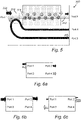
- Fig. 5 illustrates a device 500 for collecting fluorescent light according to an example not covered by the claimed invention.
- the example of Fig. 5 differs from the embodiment of Fig. 3 in that the coupler 516 is a wavelength splitter instead of a directional coupler. If two signals of different wavelengths are input at a common port of a wavelength splitter, the wavelength splitter will transmit one of the wavelengths with 100% efficiency to a first port, and couple out the other wavelength with 100% efficiency to another port. This is further illustrated in Fig. 6a .
- the wavelength splitter 516 When used in the device 500, the wavelength splitter 516 will thus transmit the excitation light 320 input at Port 1 via the first waveguide 310 to Port 2. This is further illustrated in Fig. 6b . Similarly, the collected fluorescent light 324 propagating in the first waveguide 310 from the Port 2 direction, is coupled out with 100% efficiency to the second waveguide 317 and is output at Port 3. This is further illustrated in Fig. 6c . In Fig. 6c it is also indicated (by means of the solid arrows) that some of the excitation light 320 is back-scattered such that a small amount of excitation light propagates backwards in the first waveguide 310 towards the coupler 516 (this was omitted in Fig. 4b ).
- the back-scattered excitation light is transmitted to Port 1 instead of being coupled out to Port 3.
- the power of the signal detected at Port 3 only stems from collected fluorescent light and is not contaminated by back-scattered excitation light.
- the wavelength splitter thus has an improved efficiency over the directional coupler, and also separates backscattered excitation light from collected fluorescent light.
- Fig. 7 illustrates a device 700 for collecting fluorescent light according to yet another example not covered by the claimed invention.
- the device 700 differs from the devices 300 and 500 in Figs. 3 and 5 in that the coupler 716 is a multi-mode interference coupler (MMI).
- MMI is another example of how to couple the collected fluorescent light 324 from the first waveguide 310 directly into the second waveguide 317.
- the MMI is an example of a coupler which relies on the interference pattern of the multiple of modes supported in the MMI in order to couple out light from the first waveguide 310 directly into the second waveguide 317.
- An MMI coupler basically consists of a broad, slab guide like structure which supports multiple modes. The interference pattern of theses modes is leveraged. By choosing the dimensions of the slab guide, the image at the entrance waveguide is imaged at the exit waveguide(s).
- the MMI coupler 716 transmits the excitation light 320 input at Port 1 via the first waveguide 310 to Port 2. This is further illustrated in Fig. 8a .
- the transmission is lossy and about 50% of the poser of the excitation light 320 is transmitted from Port 1 to Port 2.
- the collected fluorescent light 324 propagating in the first waveguide 310 from the Port 2 direction is split into two even sized portions, wherein one portion is transmitted via the first waveguide 310 to Port 1, and the other portion is coupled out to the second waveguide 317 and is output at Port 3.
- Fig. 8b the MMI coupler 716 operates according to another physical principle, its function is thus similar to the directional coupler described in conjunction to Fig. 3, Fig. 4a, and Fig. 4b .
- the MMI coupler 716 may also be of wavelength selective type.
- An MMI coupler of wavelength selective type is more similar in function to a wavelength splitter rather than a directional coupler. In particular, it is designed such that the excitation light 320 is output to one port, and the collected fluorescent light is output to another port.
- an MMI coupler of wavelength selective type When used in the device 700, an MMI coupler of wavelength selective type will transmit the excitation light 320 input at Port 1 via the first waveguide 310 to Port 2. This is further illustrated in Fig. 9a . Similarly, the collected fluorescent light 324 propagating in the first waveguide 310 from the Port 2 direction, is coupled out with up to 100% efficiency to the second waveguide 317 and is output at Port 3. This is further illustrated in Fig. 9b . In Fig. 9b it is also indicated (by means of the solid arrows) that some of the excitation light 320 is back-scattered such that a small amount of excitation light propagates backwards in the first waveguide 310 towards the coupler 716.
- the back-scattered excitation light is transmitted to Port 1 instead of being coupled out to Port 3.
- the power of the signal detected at Port 3 only stems from collected fluorescent light and is not contaminated by back-scattered excitation light.
- the wavelength selective MMI thus has an improved efficiency over the standard MMI of Fig. 8a and 9b , and also separates backscattered excitation light from collected fluorescent light.
- the wavelength selective MMI coupler may also comprise further output ports, wherein the MMI coupler is arranged to output different wavelengths to different ports.
- the wavelength selective MMI coupler may comprise a third waveguide to which collected fluorescent light is directly coupled, wherein fluorescent light of a first wavelength is coupled to the second waveguide, and fluorescent light of a second wavelength is coupled to the third waveguide.
- fluorescent light of a first wavelength dashed arrow
- fluorescent light of the second wavelength dotted arrow
- the third waveguide, labelled Port 5 fluorescent light of the second wavelength
- Fig. 11 shows collected signal power at Port 3 as a function of waveguide length for two different particle concentrations.
- the collected signal power measured at Port 2 using the prior art device of Figs 1a and 1b for the same two concentrations are also shown.
- Port 2 collection as explained with reference to Fig. 2 , there is an optimal waveguide length for each concentration. However, this is not the case if the fluorescent light instead is collected at Port 3 in accordance to what has been explained above with reference to Figs 3-10 .
- the power of the collected light saturates as the length of the first waveguide reaches a certain level. Moreover, that certain level is independent of the particle concentration.
- Port 3 collection it is possible to select the length of the first waveguide independently of the particle concentration.
- a single, "long enough", waveguide may be used to capture all concentrations.
- the device described with reference to Figs 3-10 may further be part of a system for detecting fluorescent light emitted by particles in a medium.
- Fig. 12 illustrates such a system 900.
- the system comprises a device 300, 500, 700 (the device 300 is illustrated, but it is understood that also the devices 500, 700 could be used), a light source 902, preferably a laser, and a detector 904.
- the detector 904 could, e.g., be an imager.
- the light source 902 may be coupled to the first waveguide of the device 300, 500, 700, for input of excitation light to the first waveguide.
- the detector 904 may be coupled to the second waveguide of the device 300, 500, 700 for detecting the collected fluorescent light which is output from Port 3 of the device. It is also possible to couple the detector to Port 2 and Port 4 (if present) of the device to detect signal power at these output ports as well, e.g., in order to determine coupling efficiency in case of a directional coupler as previously described.
- the system 900 typically comprises a non-disposable part 906, intended to be used more than one time, and a disposable part 908, intended for single use only.
- the disposable part 908 may be releasably connected to the non-disposable part.
- the more costly and bulky components, here the light source 902 and the detector 904 are arranged on the non-disposable part 908.
- the device 300, 500, 700 is, however, arranged on the disposable part 908.
- the device 300, 500, 700, and the system 900 may form part of a diagnostic device.
- the device may form part of a diagnostic device which measures the concentration of particles in a body fluid.
- the first waveguide 310 receives excitation light 320 and guides the excitation light 320 along a first direction 313 of the first waveguide 310.
- the excitation light 320 is received from a light source, such as the light source 902 of Fig. 9 .
- a light source such as the light source 902 of Fig. 9 .
- there will be an evanescent field around the first waveguide 310 which, since the first waveguide extends through the medium 302, makes it possible for the particles 304 to absorb photons of the excitation light 320. Following the absorption, the particles 304 then emit fluorescent light 322.
- Step S04 fluorescent light 322 emitted by the particles is collected by the first waveguide 310.
- Step S04 is something that happens due to interaction between the emitted fluorescent light 322 and the first waveguide 310.
- step S06 fluorescent light 324 that travels in a direction opposite to the first direction in the first waveguide is coupled out, by means of coupler 316, 516, 716, from the first waveguide 310 directly into a second waveguide 317 as previously explained.
- step S08 the collected fluorescent light is detected, by means of detector 904, at Port 3 of the second waveguide 317.
- the method may also comprise detecting light at a second end of the second waveguide, and determining a loss of the directional coupler based on a power of the detected light in relation to a power of the excitation light received by the first waveguide.
Landscapes
- Physics & Mathematics (AREA)
- General Physics & Mathematics (AREA)
- Optics & Photonics (AREA)
- Health & Medical Sciences (AREA)
- Chemical & Material Sciences (AREA)
- Engineering & Computer Science (AREA)
- Microelectronics & Electronic Packaging (AREA)
- Biochemistry (AREA)
- Life Sciences & Earth Sciences (AREA)
- Analytical Chemistry (AREA)
- General Health & Medical Sciences (AREA)
- Immunology (AREA)
- Pathology (AREA)
- Dispersion Chemistry (AREA)
- Nuclear Medicine, Radiotherapy & Molecular Imaging (AREA)
- Investigating, Analyzing Materials By Fluorescence Or Luminescence (AREA)
- Optical Integrated Circuits (AREA)
- Investigating Or Analysing Biological Materials (AREA)
- Optical Measuring Cells (AREA)
- Luminescent Compositions (AREA)
Claims (10)
- Vorrichtung (300) zum Sammeln von Fluoreszenzlicht, das durch Teilchen (304) in einem Medium (302) emittiert wird, welche Folgendes umfasst:ein Substrat (308) mit einer Kammer (306) zum Halten eines Mediums (302), das Teilchen (304) beinhaltet, die zum Emittieren von Fluoreszenzlicht in der Lage sind,einen ersten Wellenleiter (310), der auf dem Substrat (308) angeordnet ist und sich in die Kammer (306) hinein erstreckt,wobei der erste Wellenleiter (310) zum Empfangen von Anregungslicht (320) von einer Lichtquelle und Leiten des Anregungslichts (320) durch die Kammer (306) entlang einer ersten Richtung (313) des ersten Wellenliters (310) und zum Sammeln von Fluoreszenzlicht, das durch die Teilchen (304) anschließend an eine Anregung der Teilchen (304) durch das Anregungslicht (320) emittiert wird, eingerichtet ist, undeinen Koppler (316), der bei dem ersten Wellenleiter (310) angeordnet ist,dadurch gekennzeichnet, dassder Koppler (316) ein direktionaler Koppler ist und einen zweiten Wellenleiter (317) beinhaltet, der zum Ausgeben von gesammelten Fluoreszenzlicht an einem seiner Enden eingerichtet ist,wobei der zweite Wellenleiter (317) in Bezug auf den ersten Wellenleiter (310) derart angeordnet ist, dass gesammeltes Fluoreszenzlicht, das sich in einer Richtung entgegengesetzt zu der ersten Richtung (313) bewegt, von dem ersten Wellenleiter (310) direkt in den zweiten Wellenleiter (317) ausgekoppelt wird, und dass gesammeltes Fluoreszenzlicht an einem ersten Ende und Anregungslicht (320), das von dem ersten Wellenleiter (310) in den zweiten Wellenleiter (317) eingekoppelt wird, an einem zweiten Ende ausgegeben wird.
- Vorrichtung (300) nach Anspruch 1, wobei der Koppler (316) bei dem ersten Wellenleiter (310) stromaufwärts zu der Kammer (306) in Bezug auf die erste Richtung (313) angeordnet ist.
- Vorrichtung (300) nach Anspruch 1 oder 2, wobei der zweite Wellenleiter (317) angrenzend an den ersten Wellenleiter (310) angeordnet ist, wodurch ermöglicht wird, dass gesammeltes Fluoreszenzlicht, das sich in einer Richtung entgegengesetzt zu der ersten Richtung (313) bewegt, von dem ersten Wellenleiter (310) direkt in den zweiten Wellenleiter (317) ausgekoppelt wird.
- Vorrichtung (300) nach einem der vorhergehenden Ansprüche, wobei der erste Wellenleiter (310) eine Länge aufweist, die unabhängig von der Konzentration von Teilchen (304), die zum Emittieren von Fluoreszenzlicht in der Lage sind, in dem Medium (302) ausgewählt wird.
- Vorrichtung (300) nach einem der vorhergehenden Ansprüche, wobei das Substrat (308), der erste Wellenleiter (310) und der Koppler (316) auf einem Einwegchip angeordnet sind.
- System zum Detektieren von Fluoreszenzlicht, das durch Teilchen (304) in einem Medium (302) emittiert wird, welches Folgendes umfasst:eine Vorrichtung (300) zum Sammeln von Fluoreszenzlicht, das durch Teilchen (304) in einem Medium (302) emittiert wird, nach einem der Ansprüche 1-5,eine Lichtquelle, die mit dem ersten Wellenleiter (310) der Vorrichtung (300) gekoppelt ist, zum Eingeben von Anregungslicht (320) in den ersten Wellenleiter (310), undeinen Detektor, der mit dem zweiten Wellenleiter (317) der Vorrichtung (300) gekoppelt ist, zum Detektieren des gesammelten Fluoreszenzlichts, das von einem der Enden des zweiten Wellenleiters (317) ausgegeben wird.
- System nach Anspruch 6, wobei das System einen Einwegteil und einen Nichteinwegteil umfasst, wobei der Einwegteil dazu eingerichtet ist, mit dem Nichteinwegteil verbunden zu werden,
wobei die Lichtquelle und der Detektor auf dem Nichteinwegteil angeordnet sind und die Vorrichtung (300) auf dem Einwegteil angeordnet ist. - System nach einem der Ansprüche 6-7, wobei der Detektor ferner mit dem zweiten Ende des zweiten Wellenleiters (317) zum Detektieren von Licht gekoppelt ist, das an dem zweiten Ende ausgegeben wird, und wobei das System zum Bestimmen eines Verlusts des direktionalen Kopplers basierend auf einer Leistung des Lichts, das an dem zweiten Ende des zweiten Wellenleiters (317) ausgegeben wird, in Relation zu einer Leistung des Anregungslichts (320), das in den ersten Wellenleiter (310) eingegeben ist, konfiguriert ist.
- Diagnoseanordnung, die die Vorrichtung (300) nach einem der Ansprüche 1-5 oder das System nach einem der Ansprüche 6-8 umfasst.
- Verfahren zum Detektieren von Fluoreszenzlicht, das durch Teilchen (304) in einem Medium (302) emittiert wird, unter Verwendung der Vorrichtung (300) nach einem der Ansprüche 1-5 oder des Systems nach einem der Ansprüche 6-8 oder der Diagnoseanordnung nach Anspruch 9, welches Folgendes umfasst:Empfangen von Anregungslicht (320) durch den ersten Wellenleiter (310) und Leiten des Anregungslichts (320) entlang einer ersten Richtung (313) des ersten Wellenleiters (310), wobei sich ein Teil des ersten Wellenleiters (310) durch das Medium (302) erstreckt, das die Teilchen (304) beinhaltet, die zum Emittieren von Fluoreszenzlicht in der Lage sind,Sammeln, unter Verwendung des ersten Wellenleiters (310), von Fluoreszenzlicht, das durch die Teilchen (304) anschließend an eine Anregung durch das Anregungslicht (320) emittiert wird,Auskoppeln, unter Verwendung des direktionalen Kopplers (316), der bei dem ersten Wellenleiter (310) angeordnet ist, von Fluoreszenzlicht, das sich in einer Richtung entgegengesetzt zu der ersten Richtung (313) bewegt, von dem ersten Wellenleiter (310) direkt in den zweiten Wellenleiter (317) des Kopplers (316),Detektieren, unter Verwendung eines Detektors, des gesammelten Fluoreszenzlichts an dem ersten Ende des zweiten Wellenleiters (317),Detektieren von Anregungslicht an dem zweiten Ende des zweiten Wellenleiters (317), undBestimmen eines Verlusts des direktionalen Kopplers (316) basierend auf einer Leistung des detektierten Anregungslichts in Relation zu einer Leistung des Anregungslichts (320), das durch den ersten Wellenleiter (310) empfangen wird.
Priority Applications (1)
| Application Number | Priority Date | Filing Date | Title |
|---|---|---|---|
| EP22198008.9A EP4134661A1 (de) | 2016-12-21 | 2017-12-12 | Vorrichtung zum sammeln von fluoreszierendem licht, das von partikeln in einem medium emittiert wird |
Applications Claiming Priority (2)
| Application Number | Priority Date | Filing Date | Title |
|---|---|---|---|
| EP16205663 | 2016-12-21 | ||
| PCT/EP2017/082391 WO2018114475A1 (en) | 2016-12-21 | 2017-12-12 | Device for collecting fluorescent light emitted by particles in a medium |
Related Child Applications (1)
| Application Number | Title | Priority Date | Filing Date |
|---|---|---|---|
| EP22198008.9A Division EP4134661A1 (de) | 2016-12-21 | 2017-12-12 | Vorrichtung zum sammeln von fluoreszierendem licht, das von partikeln in einem medium emittiert wird |
Publications (2)
| Publication Number | Publication Date |
|---|---|
| EP3559638A1 EP3559638A1 (de) | 2019-10-30 |
| EP3559638B1 true EP3559638B1 (de) | 2022-09-28 |
Family
ID=57583051
Family Applications (2)
| Application Number | Title | Priority Date | Filing Date |
|---|---|---|---|
| EP22198008.9A Withdrawn EP4134661A1 (de) | 2016-12-21 | 2017-12-12 | Vorrichtung zum sammeln von fluoreszierendem licht, das von partikeln in einem medium emittiert wird |
| EP17817715.0A Active EP3559638B1 (de) | 2016-12-21 | 2017-12-12 | Vorrichtung zur erfassung von emittiertem fluoreszierendem licht von partikeln in einem medium |
Family Applications Before (1)
| Application Number | Title | Priority Date | Filing Date |
|---|---|---|---|
| EP22198008.9A Withdrawn EP4134661A1 (de) | 2016-12-21 | 2017-12-12 | Vorrichtung zum sammeln von fluoreszierendem licht, das von partikeln in einem medium emittiert wird |
Country Status (7)
| Country | Link |
|---|---|
| US (1) | US11686682B2 (de) |
| EP (2) | EP4134661A1 (de) |
| JP (1) | JP7183160B2 (de) |
| CN (1) | CN110088598B (de) |
| AU (2) | AU2017384022A1 (de) |
| ES (1) | ES2934786T3 (de) |
| WO (1) | WO2018114475A1 (de) |
Families Citing this family (2)
| Publication number | Priority date | Publication date | Assignee | Title |
|---|---|---|---|---|
| DE112022001270T5 (de) * | 2021-06-25 | 2024-01-04 | Ams-Osram Ag | Schwebstoffdetektor und verfahren zum nachweis von schwebstoffen |
| CN114689510B (zh) * | 2022-03-15 | 2025-08-05 | 南京大学 | 一种片上荧光激发与采集系统 |
Family Cites Families (11)
| Publication number | Priority date | Publication date | Assignee | Title |
|---|---|---|---|---|
| US5569911A (en) * | 1993-07-19 | 1996-10-29 | General Electric Company | Fiber optic system for remote fluorescent sensing using excitation and return fibers |
| US6075611A (en) | 1998-05-07 | 2000-06-13 | Schlumberger Technology Corporation | Methods and apparatus utilizing a derivative of a fluorescene signal for measuring the characteristics of a multiphase fluid flow in a hydrocarbon well |
| US6850317B2 (en) * | 2001-01-23 | 2005-02-01 | Schlumberger Technology Corporation | Apparatus and methods for determining velocity of oil in a flow stream |
| US8675199B2 (en) | 2006-03-10 | 2014-03-18 | Plc Diagnostics, Inc. | Waveguide-based detection system with scanning light source |
| US9528939B2 (en) * | 2006-03-10 | 2016-12-27 | Indx Lifecare, Inc. | Waveguide-based optical scanning systems |
| US7508999B2 (en) | 2007-03-02 | 2009-03-24 | Johns Hopkins University | Fiber optic sensor device for measuring chromophoric compounds in biological fluid |
| KR101045206B1 (ko) * | 2008-10-31 | 2011-06-30 | 삼성전자주식회사 | 여기광 흡수 도파로가 삽입된 집적된 바이오칩 및 그 제조방법 |
| CN101893562B (zh) * | 2010-06-22 | 2011-12-21 | 浙江大学 | 基于数字式微滴进样通道的高灵敏度集成光波导传感器件 |
| US20140125983A1 (en) | 2011-05-31 | 2014-05-08 | Tornado Medical Systems, Inc. | Interferometery on a planar substrate |
| US9234854B2 (en) * | 2013-03-15 | 2016-01-12 | International Business Machines Corporation | Single fiber noncritical-alignment wafer-scale optical testing |
| GB2539017B (en) | 2015-06-03 | 2019-12-18 | Toshiba Res Europe Limited | An optical measuring device |
-
2017
- 2017-12-12 CN CN201780078344.6A patent/CN110088598B/zh active Active
- 2017-12-12 AU AU2017384022A patent/AU2017384022A1/en not_active Abandoned
- 2017-12-12 EP EP22198008.9A patent/EP4134661A1/de not_active Withdrawn
- 2017-12-12 JP JP2019531882A patent/JP7183160B2/ja active Active
- 2017-12-12 EP EP17817715.0A patent/EP3559638B1/de active Active
- 2017-12-12 ES ES17817715T patent/ES2934786T3/es active Active
- 2017-12-12 WO PCT/EP2017/082391 patent/WO2018114475A1/en not_active Ceased
- 2017-12-12 US US16/471,555 patent/US11686682B2/en active Active
-
2021
- 2021-01-29 AU AU2021200614A patent/AU2021200614B2/en not_active Ceased
Also Published As
| Publication number | Publication date |
|---|---|
| JP2020514690A (ja) | 2020-05-21 |
| JP7183160B2 (ja) | 2022-12-05 |
| CA3044733A1 (en) | 2018-06-28 |
| CN110088598B (zh) | 2022-01-14 |
| EP4134661A1 (de) | 2023-02-15 |
| WO2018114475A1 (en) | 2018-06-28 |
| AU2017384022A1 (en) | 2019-06-06 |
| AU2021200614A1 (en) | 2021-03-04 |
| CN110088598A (zh) | 2019-08-02 |
| AU2021200614B2 (en) | 2022-09-22 |
| EP3559638A1 (de) | 2019-10-30 |
| US20200371030A1 (en) | 2020-11-26 |
| US11686682B2 (en) | 2023-06-27 |
| ES2934786T3 (es) | 2023-02-27 |
Similar Documents
| Publication | Publication Date | Title |
|---|---|---|
| US7885490B2 (en) | Optical chemical detector and method | |
| US20230358958A1 (en) | Sliced grating coupler with increased beam alignment sensitivity | |
| CN101493410B (zh) | 基于波分复用技术的多通道光微流体传感器及传感装置 | |
| US20100032582A1 (en) | Fluorescence detection system and method | |
| US5569911A (en) | Fiber optic system for remote fluorescent sensing using excitation and return fibers | |
| US9372150B2 (en) | Optical method and system for measuring an environmental parameter | |
| AU2021200614B2 (en) | Device for Collecting Fluorescent Light Emitted by Particles in a Medium | |
| US7221450B2 (en) | Dual wavelength optical analyser | |
| CN101666747A (zh) | 阵列光纤倏逝波生物传感器系统 | |
| US8792103B2 (en) | System for analysis of a fluid | |
| EP2249146A1 (de) | Photonenkristallfasersensor | |
| US8253933B2 (en) | Waveguide-based sensor | |
| US20240019356A1 (en) | An optical absorbance spectrometer, optical device and method of optical absorbance spectrometry | |
| CA3044733C (en) | Device for collecting fluorescent light emitted by particles in a medium | |
| US9244002B1 (en) | Optical method and system for measuring an environmental parameter | |
| US20080089635A1 (en) | Single Analyte Molecule Detection by Fibre Fluorescemce Probe | |
| TWI923402B (zh) | 複合波長雷射光源的光感測裝置 | |
| WO2019058097A1 (en) | APPARATUS AND METHOD FOR DETECTING A TRACKER | |
| KR100211725B1 (ko) | 광학간섭필터를 이용한 광분파기 | |
| Samir et al. | An Overview of Fiber Fluorimeter Probes |
Legal Events
| Date | Code | Title | Description |
|---|---|---|---|
| STAA | Information on the status of an ep patent application or granted ep patent |
Free format text: STATUS: UNKNOWN |
|
| STAA | Information on the status of an ep patent application or granted ep patent |
Free format text: STATUS: THE INTERNATIONAL PUBLICATION HAS BEEN MADE |
|
| PUAI | Public reference made under article 153(3) epc to a published international application that has entered the european phase |
Free format text: ORIGINAL CODE: 0009012 |
|
| STAA | Information on the status of an ep patent application or granted ep patent |
Free format text: STATUS: REQUEST FOR EXAMINATION WAS MADE |
|
| 17P | Request for examination filed |
Effective date: 20190624 |
|
| AK | Designated contracting states |
Kind code of ref document: A1 Designated state(s): AL AT BE BG CH CY CZ DE DK EE ES FI FR GB GR HR HU IE IS IT LI LT LU LV MC MK MT NL NO PL PT RO RS SE SI SK SM TR |
|
| AX | Request for extension of the european patent |
Extension state: BA ME |
|
| DAV | Request for validation of the european patent (deleted) | ||
| DAX | Request for extension of the european patent (deleted) | ||
| STAA | Information on the status of an ep patent application or granted ep patent |
Free format text: STATUS: EXAMINATION IS IN PROGRESS |
|
| 17Q | First examination report despatched |
Effective date: 20200729 |
|
| RAP3 | Party data changed (applicant data changed or rights of an application transferred) |
Owner name: MIDIAGNOSTICS NV |
|
| GRAP | Despatch of communication of intention to grant a patent |
Free format text: ORIGINAL CODE: EPIDOSNIGR1 |
|
| STAA | Information on the status of an ep patent application or granted ep patent |
Free format text: STATUS: GRANT OF PATENT IS INTENDED |
|
| RIC1 | Information provided on ipc code assigned before grant |
Ipc: G02B 6/293 20060101ALI20220518BHEP Ipc: G02B 6/125 20060101ALI20220518BHEP Ipc: G01N 15/06 20060101ALI20220518BHEP Ipc: G02B 6/28 20060101ALI20220518BHEP Ipc: G02B 6/12 20060101ALI20220518BHEP Ipc: G01N 15/14 20060101ALI20220518BHEP Ipc: G01J 3/44 20060101ALI20220518BHEP Ipc: G01N 21/64 20060101AFI20220518BHEP |
|
| INTG | Intention to grant announced |
Effective date: 20220608 |
|
| GRAS | Grant fee paid |
Free format text: ORIGINAL CODE: EPIDOSNIGR3 |
|
| GRAA | (expected) grant |
Free format text: ORIGINAL CODE: 0009210 |
|
| STAA | Information on the status of an ep patent application or granted ep patent |
Free format text: STATUS: THE PATENT HAS BEEN GRANTED |
|
| AK | Designated contracting states |
Kind code of ref document: B1 Designated state(s): AL AT BE BG CH CY CZ DE DK EE ES FI FR GB GR HR HU IE IS IT LI LT LU LV MC MK MT NL NO PL PT RO RS SE SI SK SM TR |
|
| REG | Reference to a national code |
Ref country code: GB Ref legal event code: FG4D |
|
| REG | Reference to a national code |
Ref country code: CH Ref legal event code: EP |
|
| REG | Reference to a national code |
Ref country code: AT Ref legal event code: REF Ref document number: 1521549 Country of ref document: AT Kind code of ref document: T Effective date: 20221015 |
|
| REG | Reference to a national code |
Ref country code: DE Ref legal event code: R096 Ref document number: 602017062205 Country of ref document: DE |
|
| REG | Reference to a national code |
Ref country code: IE Ref legal event code: FG4D |
|
| REG | Reference to a national code |
Ref country code: LT Ref legal event code: MG9D |
|
| PG25 | Lapsed in a contracting state [announced via postgrant information from national office to epo] |
Ref country code: SE Free format text: LAPSE BECAUSE OF FAILURE TO SUBMIT A TRANSLATION OF THE DESCRIPTION OR TO PAY THE FEE WITHIN THE PRESCRIBED TIME-LIMIT Effective date: 20220928 Ref country code: RS Free format text: LAPSE BECAUSE OF FAILURE TO SUBMIT A TRANSLATION OF THE DESCRIPTION OR TO PAY THE FEE WITHIN THE PRESCRIBED TIME-LIMIT Effective date: 20220928 Ref country code: NO Free format text: LAPSE BECAUSE OF FAILURE TO SUBMIT A TRANSLATION OF THE DESCRIPTION OR TO PAY THE FEE WITHIN THE PRESCRIBED TIME-LIMIT Effective date: 20221228 Ref country code: LV Free format text: LAPSE BECAUSE OF FAILURE TO SUBMIT A TRANSLATION OF THE DESCRIPTION OR TO PAY THE FEE WITHIN THE PRESCRIBED TIME-LIMIT Effective date: 20220928 Ref country code: LT Free format text: LAPSE BECAUSE OF FAILURE TO SUBMIT A TRANSLATION OF THE DESCRIPTION OR TO PAY THE FEE WITHIN THE PRESCRIBED TIME-LIMIT Effective date: 20220928 Ref country code: FI Free format text: LAPSE BECAUSE OF FAILURE TO SUBMIT A TRANSLATION OF THE DESCRIPTION OR TO PAY THE FEE WITHIN THE PRESCRIBED TIME-LIMIT Effective date: 20220928 |
|
| REG | Reference to a national code |
Ref country code: NL Ref legal event code: MP Effective date: 20220928 |
|
| REG | Reference to a national code |
Ref country code: AT Ref legal event code: MK05 Ref document number: 1521549 Country of ref document: AT Kind code of ref document: T Effective date: 20220928 |
|
| REG | Reference to a national code |
Ref country code: ES Ref legal event code: FG2A Ref document number: 2934786 Country of ref document: ES Kind code of ref document: T3 Effective date: 20230227 |
|
| PG25 | Lapsed in a contracting state [announced via postgrant information from national office to epo] |
Ref country code: HR Free format text: LAPSE BECAUSE OF FAILURE TO SUBMIT A TRANSLATION OF THE DESCRIPTION OR TO PAY THE FEE WITHIN THE PRESCRIBED TIME-LIMIT Effective date: 20220928 Ref country code: GR Free format text: LAPSE BECAUSE OF FAILURE TO SUBMIT A TRANSLATION OF THE DESCRIPTION OR TO PAY THE FEE WITHIN THE PRESCRIBED TIME-LIMIT Effective date: 20221229 |
|
| PG25 | Lapsed in a contracting state [announced via postgrant information from national office to epo] |
Ref country code: SM Free format text: LAPSE BECAUSE OF FAILURE TO SUBMIT A TRANSLATION OF THE DESCRIPTION OR TO PAY THE FEE WITHIN THE PRESCRIBED TIME-LIMIT Effective date: 20220928 Ref country code: RO Free format text: LAPSE BECAUSE OF FAILURE TO SUBMIT A TRANSLATION OF THE DESCRIPTION OR TO PAY THE FEE WITHIN THE PRESCRIBED TIME-LIMIT Effective date: 20220928 Ref country code: PT Free format text: LAPSE BECAUSE OF FAILURE TO SUBMIT A TRANSLATION OF THE DESCRIPTION OR TO PAY THE FEE WITHIN THE PRESCRIBED TIME-LIMIT Effective date: 20230130 Ref country code: CZ Free format text: LAPSE BECAUSE OF FAILURE TO SUBMIT A TRANSLATION OF THE DESCRIPTION OR TO PAY THE FEE WITHIN THE PRESCRIBED TIME-LIMIT Effective date: 20220928 Ref country code: AT Free format text: LAPSE BECAUSE OF FAILURE TO SUBMIT A TRANSLATION OF THE DESCRIPTION OR TO PAY THE FEE WITHIN THE PRESCRIBED TIME-LIMIT Effective date: 20220928 |
|
| PG25 | Lapsed in a contracting state [announced via postgrant information from national office to epo] |
Ref country code: SK Free format text: LAPSE BECAUSE OF FAILURE TO SUBMIT A TRANSLATION OF THE DESCRIPTION OR TO PAY THE FEE WITHIN THE PRESCRIBED TIME-LIMIT Effective date: 20220928 Ref country code: PL Free format text: LAPSE BECAUSE OF FAILURE TO SUBMIT A TRANSLATION OF THE DESCRIPTION OR TO PAY THE FEE WITHIN THE PRESCRIBED TIME-LIMIT Effective date: 20220928 Ref country code: IS Free format text: LAPSE BECAUSE OF FAILURE TO SUBMIT A TRANSLATION OF THE DESCRIPTION OR TO PAY THE FEE WITHIN THE PRESCRIBED TIME-LIMIT Effective date: 20230128 Ref country code: EE Free format text: LAPSE BECAUSE OF FAILURE TO SUBMIT A TRANSLATION OF THE DESCRIPTION OR TO PAY THE FEE WITHIN THE PRESCRIBED TIME-LIMIT Effective date: 20220928 |
|
| RAP4 | Party data changed (patent owner data changed or rights of a patent transferred) |
Owner name: MIDIAGNOSTICS NV |
|
| P01 | Opt-out of the competence of the unified patent court (upc) registered |
Effective date: 20230508 |
|
| REG | Reference to a national code |
Ref country code: DE Ref legal event code: R097 Ref document number: 602017062205 Country of ref document: DE |
|
| PG25 | Lapsed in a contracting state [announced via postgrant information from national office to epo] |
Ref country code: NL Free format text: LAPSE BECAUSE OF FAILURE TO SUBMIT A TRANSLATION OF THE DESCRIPTION OR TO PAY THE FEE WITHIN THE PRESCRIBED TIME-LIMIT Effective date: 20220928 Ref country code: AL Free format text: LAPSE BECAUSE OF FAILURE TO SUBMIT A TRANSLATION OF THE DESCRIPTION OR TO PAY THE FEE WITHIN THE PRESCRIBED TIME-LIMIT Effective date: 20220928 |
|
| PG25 | Lapsed in a contracting state [announced via postgrant information from national office to epo] |
Ref country code: DK Free format text: LAPSE BECAUSE OF FAILURE TO SUBMIT A TRANSLATION OF THE DESCRIPTION OR TO PAY THE FEE WITHIN THE PRESCRIBED TIME-LIMIT Effective date: 20220928 |
|
| REG | Reference to a national code |
Ref country code: CH Ref legal event code: PL |
|
| PLBE | No opposition filed within time limit |
Free format text: ORIGINAL CODE: 0009261 |
|
| STAA | Information on the status of an ep patent application or granted ep patent |
Free format text: STATUS: NO OPPOSITION FILED WITHIN TIME LIMIT |
|
| PG25 | Lapsed in a contracting state [announced via postgrant information from national office to epo] |
Ref country code: LU Free format text: LAPSE BECAUSE OF NON-PAYMENT OF DUE FEES Effective date: 20221212 |
|
| 26N | No opposition filed |
Effective date: 20230629 |
|
| PG25 | Lapsed in a contracting state [announced via postgrant information from national office to epo] |
Ref country code: LI Free format text: LAPSE BECAUSE OF NON-PAYMENT OF DUE FEES Effective date: 20221231 Ref country code: IE Free format text: LAPSE BECAUSE OF NON-PAYMENT OF DUE FEES Effective date: 20221212 Ref country code: CH Free format text: LAPSE BECAUSE OF NON-PAYMENT OF DUE FEES Effective date: 20221231 |
|
| PG25 | Lapsed in a contracting state [announced via postgrant information from national office to epo] |
Ref country code: SI Free format text: LAPSE BECAUSE OF FAILURE TO SUBMIT A TRANSLATION OF THE DESCRIPTION OR TO PAY THE FEE WITHIN THE PRESCRIBED TIME-LIMIT Effective date: 20220928 |
|
| PG25 | Lapsed in a contracting state [announced via postgrant information from national office to epo] |
Ref country code: HU Free format text: LAPSE BECAUSE OF FAILURE TO SUBMIT A TRANSLATION OF THE DESCRIPTION OR TO PAY THE FEE WITHIN THE PRESCRIBED TIME-LIMIT; INVALID AB INITIO Effective date: 20171212 |
|
| PG25 | Lapsed in a contracting state [announced via postgrant information from national office to epo] |
Ref country code: CY Free format text: LAPSE BECAUSE OF FAILURE TO SUBMIT A TRANSLATION OF THE DESCRIPTION OR TO PAY THE FEE WITHIN THE PRESCRIBED TIME-LIMIT Effective date: 20220928 |
|
| PG25 | Lapsed in a contracting state [announced via postgrant information from national office to epo] |
Ref country code: MK Free format text: LAPSE BECAUSE OF FAILURE TO SUBMIT A TRANSLATION OF THE DESCRIPTION OR TO PAY THE FEE WITHIN THE PRESCRIBED TIME-LIMIT Effective date: 20220928 |
|
| PG25 | Lapsed in a contracting state [announced via postgrant information from national office to epo] |
Ref country code: MC Free format text: LAPSE BECAUSE OF FAILURE TO SUBMIT A TRANSLATION OF THE DESCRIPTION OR TO PAY THE FEE WITHIN THE PRESCRIBED TIME-LIMIT Effective date: 20220928 |
|
| PG25 | Lapsed in a contracting state [announced via postgrant information from national office to epo] |
Ref country code: TR Free format text: LAPSE BECAUSE OF FAILURE TO SUBMIT A TRANSLATION OF THE DESCRIPTION OR TO PAY THE FEE WITHIN THE PRESCRIBED TIME-LIMIT Effective date: 20220928 Ref country code: MC Free format text: LAPSE BECAUSE OF FAILURE TO SUBMIT A TRANSLATION OF THE DESCRIPTION OR TO PAY THE FEE WITHIN THE PRESCRIBED TIME-LIMIT Effective date: 20220928 |
|
| PG25 | Lapsed in a contracting state [announced via postgrant information from national office to epo] |
Ref country code: BG Free format text: LAPSE BECAUSE OF FAILURE TO SUBMIT A TRANSLATION OF THE DESCRIPTION OR TO PAY THE FEE WITHIN THE PRESCRIBED TIME-LIMIT Effective date: 20220928 |
|
| PG25 | Lapsed in a contracting state [announced via postgrant information from national office to epo] |
Ref country code: MT Free format text: LAPSE BECAUSE OF FAILURE TO SUBMIT A TRANSLATION OF THE DESCRIPTION OR TO PAY THE FEE WITHIN THE PRESCRIBED TIME-LIMIT Effective date: 20220928 |
|
| PGFP | Annual fee paid to national office [announced via postgrant information from national office to epo] |
Ref country code: DE Payment date: 20251121 Year of fee payment: 9 |
|
| PGFP | Annual fee paid to national office [announced via postgrant information from national office to epo] |
Ref country code: GB Payment date: 20251117 Year of fee payment: 9 |
|
| PGFP | Annual fee paid to national office [announced via postgrant information from national office to epo] |
Ref country code: IT Payment date: 20251121 Year of fee payment: 9 |
|
| PGFP | Annual fee paid to national office [announced via postgrant information from national office to epo] |
Ref country code: FR Payment date: 20251117 Year of fee payment: 9 |
|
| PGFP | Annual fee paid to national office [announced via postgrant information from national office to epo] |
Ref country code: BE Payment date: 20251118 Year of fee payment: 9 |
|
| PGFP | Annual fee paid to national office [announced via postgrant information from national office to epo] |
Ref country code: ES Payment date: 20260102 Year of fee payment: 9 |