EP3559855B1 - Weisse beleuchtung für strichcode-scanner mit verbesserter leistungseffizienz und kosten - Google Patents
Weisse beleuchtung für strichcode-scanner mit verbesserter leistungseffizienz und kosten Download PDFInfo
- Publication number
- EP3559855B1 EP3559855B1 EP17883240.8A EP17883240A EP3559855B1 EP 3559855 B1 EP3559855 B1 EP 3559855B1 EP 17883240 A EP17883240 A EP 17883240A EP 3559855 B1 EP3559855 B1 EP 3559855B1
- Authority
- EP
- European Patent Office
- Prior art keywords
- color led
- light source
- led light
- color
- led
- Prior art date
- Legal status (The legal status is an assumption and is not a legal conclusion. Google has not performed a legal analysis and makes no representation as to the accuracy of the status listed.)
- Active
Links
Images




Classifications
-
- G—PHYSICS
- G06—COMPUTING OR CALCULATING; COUNTING
- G06K—GRAPHICAL DATA READING; PRESENTATION OF DATA; RECORD CARRIERS; HANDLING RECORD CARRIERS
- G06K7/00—Methods or arrangements for sensing record carriers, e.g. for reading patterns
- G06K7/10—Methods or arrangements for sensing record carriers, e.g. for reading patterns by electromagnetic radiation, e.g. optical sensing; by corpuscular radiation
- G06K7/14—Methods or arrangements for sensing record carriers, e.g. for reading patterns by electromagnetic radiation, e.g. optical sensing; by corpuscular radiation using light without selection of wavelength, e.g. sensing reflected white light
- G06K7/1404—Methods for optical code recognition
- G06K7/146—Methods for optical code recognition the method including quality enhancement steps
- G06K7/1478—Methods for optical code recognition the method including quality enhancement steps adapting the threshold for pixels in a CMOS or CCD pixel sensor for black and white recognition
-
- G—PHYSICS
- G06—COMPUTING OR CALCULATING; COUNTING
- G06K—GRAPHICAL DATA READING; PRESENTATION OF DATA; RECORD CARRIERS; HANDLING RECORD CARRIERS
- G06K7/00—Methods or arrangements for sensing record carriers, e.g. for reading patterns
- G06K7/10—Methods or arrangements for sensing record carriers, e.g. for reading patterns by electromagnetic radiation, e.g. optical sensing; by corpuscular radiation
- G06K7/14—Methods or arrangements for sensing record carriers, e.g. for reading patterns by electromagnetic radiation, e.g. optical sensing; by corpuscular radiation using light without selection of wavelength, e.g. sensing reflected white light
-
- G—PHYSICS
- G06—COMPUTING OR CALCULATING; COUNTING
- G06K—GRAPHICAL DATA READING; PRESENTATION OF DATA; RECORD CARRIERS; HANDLING RECORD CARRIERS
- G06K19/00—Record carriers for use with machines and with at least a part designed to carry digital markings
- G06K19/06—Record carriers for use with machines and with at least a part designed to carry digital markings characterised by the kind of the digital marking, e.g. shape, nature, code
- G06K19/06009—Record carriers for use with machines and with at least a part designed to carry digital markings characterised by the kind of the digital marking, e.g. shape, nature, code with optically detectable marking
- G06K19/06018—Record carriers for use with machines and with at least a part designed to carry digital markings characterised by the kind of the digital marking, e.g. shape, nature, code with optically detectable marking one-dimensional coding
- G06K19/06028—Record carriers for use with machines and with at least a part designed to carry digital markings characterised by the kind of the digital marking, e.g. shape, nature, code with optically detectable marking one-dimensional coding using bar codes
-
- G—PHYSICS
- G06—COMPUTING OR CALCULATING; COUNTING
- G06K—GRAPHICAL DATA READING; PRESENTATION OF DATA; RECORD CARRIERS; HANDLING RECORD CARRIERS
- G06K19/00—Record carriers for use with machines and with at least a part designed to carry digital markings
- G06K19/06—Record carriers for use with machines and with at least a part designed to carry digital markings characterised by the kind of the digital marking, e.g. shape, nature, code
- G06K19/06009—Record carriers for use with machines and with at least a part designed to carry digital markings characterised by the kind of the digital marking, e.g. shape, nature, code with optically detectable marking
- G06K19/06046—Constructional details
- G06K19/0614—Constructional details the marking being selective to wavelength, e.g. color barcode or barcodes only visible under UV or IR
-
- G—PHYSICS
- G06—COMPUTING OR CALCULATING; COUNTING
- G06K—GRAPHICAL DATA READING; PRESENTATION OF DATA; RECORD CARRIERS; HANDLING RECORD CARRIERS
- G06K7/00—Methods or arrangements for sensing record carriers, e.g. for reading patterns
- G06K7/10—Methods or arrangements for sensing record carriers, e.g. for reading patterns by electromagnetic radiation, e.g. optical sensing; by corpuscular radiation
- G06K7/10544—Methods or arrangements for sensing record carriers, e.g. for reading patterns by electromagnetic radiation, e.g. optical sensing; by corpuscular radiation by scanning of the records by radiation in the optical part of the electromagnetic spectrum
- G06K7/10712—Fixed beam scanning
- G06K7/10722—Photodetector array or CCD scanning
- G06K7/10732—Light sources
-
- G—PHYSICS
- G06—COMPUTING OR CALCULATING; COUNTING
- G06K—GRAPHICAL DATA READING; PRESENTATION OF DATA; RECORD CARRIERS; HANDLING RECORD CARRIERS
- G06K7/00—Methods or arrangements for sensing record carriers, e.g. for reading patterns
- G06K7/10—Methods or arrangements for sensing record carriers, e.g. for reading patterns by electromagnetic radiation, e.g. optical sensing; by corpuscular radiation
- G06K7/10544—Methods or arrangements for sensing record carriers, e.g. for reading patterns by electromagnetic radiation, e.g. optical sensing; by corpuscular radiation by scanning of the records by radiation in the optical part of the electromagnetic spectrum
- G06K7/10712—Fixed beam scanning
- G06K7/10722—Photodetector array or CCD scanning
- G06K7/10742—Photodetector array or CCD scanning including a diffuser for diffusing the light from the light source to create substantially uniform illumination of the target record carrier
-
- G—PHYSICS
- G06—COMPUTING OR CALCULATING; COUNTING
- G06K—GRAPHICAL DATA READING; PRESENTATION OF DATA; RECORD CARRIERS; HANDLING RECORD CARRIERS
- G06K7/00—Methods or arrangements for sensing record carriers, e.g. for reading patterns
- G06K7/10—Methods or arrangements for sensing record carriers, e.g. for reading patterns by electromagnetic radiation, e.g. optical sensing; by corpuscular radiation
- G06K7/14—Methods or arrangements for sensing record carriers, e.g. for reading patterns by electromagnetic radiation, e.g. optical sensing; by corpuscular radiation using light without selection of wavelength, e.g. sensing reflected white light
- G06K7/1404—Methods for optical code recognition
- G06K7/1408—Methods for optical code recognition the method being specifically adapted for the type of code
- G06K7/1413—1D bar codes
Definitions
- Machine readable codes such as barcodes, QR codes, visual features or patterns, and watermarks, such as the Digimarc® barcode, are essentially representation of information in a visual format. Such codes may include data characters and/or overhead characters represented by a particular sequence of bars and/or spaces that may have varying widths. Such codes have widespread applications. For example, machine readable codes can be used to identify a class of objects or unique items. As a result, these codes are found on a wide variety of objects, such as documents, retail goods, shipping boxes, product parts, company assets, and so on.
- a laser based barcode scanner typically moves, i.e. scans, a laser light beam across the barcode.
- Imaging based barcode scanners typically include solid state image circuitry, such as charge coupled devices (CCD) or complementary metal-oxide semiconductor (CMOS) devices, and may be implemented using a one-dimensional or two-dimensional imaging array of photo sensors or pixels to capture an image of the optical code.
- CCD charge coupled devices
- CMOS complementary metal-oxide semiconductor
- One-dimensional CCD readers capture a linear cross section of the code, producing an analog waveform whose amplitude represents the relative darkness and lightness of the code.
- Two-dimensional CCD or CMOS readers may capture an entire two-dimensional image.
- imaging readers may utilize an illumination source to illuminate the optical code in an attempt to improve the image data quality generated by the imaging device as well as to provide a certain signal response in the imaging device.
- a source of illumination can reduce exposure time and thereby improving imager performance, especially in low ambient light conditions and when imaging moving items.
- active illumination for scanners is to provide good contrast on an image sensor for readable optical indicia that include barcode labels, digital watermark labels, and visual features or patterns, etc., on objects and/or package surfaces; while minimizing visibility and distraction of the illumination to users.
- RGB lights red light, green light, and blue light
- RGB lights red light, green light, and blue light
- RGB lights red light, green light, and blue light
- RGB LED chip power ratings are similar for typical RGB LEDs, those LEDs are relatively expensive, while a green LED in the tri-color LED package can be eliminated functionally for scanner active illumination.
- the respective wavelengths of red and blue (R and B) colors are not ideal for scanner applications.
- white light LEDs are typically produced is by coupling an LED of one color with a phosphor coating of a different color to produce white light. As illustrated in FIG.
- a light source that appears to be white is constructed from a blue LED 202 , such as an LED made from an indium gallium nitride semiconductor transmitting blue light 204 , that is covered with a layer of phosphor 206 that converts a portion of the blue light to a broad band of yellow light 208 .
- a blue LED 202 such as an LED made from an indium gallium nitride semiconductor transmitting blue light 204
- a layer of phosphor 206 that converts a portion of the blue light to a broad band of yellow light 208 .
- the resultant light source appears white.
- the overall efficiency of the phosphor-converted light source is determined by the efficiency with which the LED converts electricity to light and the efficiency with which the LED light is down-converted to white light in the portion of the spectrum to which the eye is sensitive.
- FIG. 1A is an illustration of an illustrative item processing system 100 .
- the item processing system 100 is a barcode scanning system.
- the item processing system 100 may include a camera 102 configured to capture images of an object 104 and generate image data 106.
- the image data 106 captured by the camera 102 may be communicated to a computer system 108 for processing thereby.
- the camera 102 may be configured to process the image data 106 .
- the system 100 shows a single camera 102 , multiple cameras may be utilized to capture images from similar or different angles.
- a barcode scanner may include a scanner that is configured to scan machine readable indicia, including watermarks, as described herein.
- the camera 102 may be coupled to or include multiple different color light sources.
- the color light sources are light emitting diodes (LEDs), such as organic LEDs.
- the plurality of color light sources may include a first LED unit 110a , a second LED unit 110b , and a third LED unit 110c (collectively 110 ).
- the system 100 may include more than the three LED units 110 without diverging from the scope of the disclosed embodiments.
- Each of the LED units 110 may include one or more LEDs of the same or different colors configured to produce light at the same or different wavelengths.
- each of the LED units 110 may include one or more LEDs upon which color-specific control signals may be applied to produce a desired color from each of the respective LED units 110 .
- the system 100 includes controller electronics 112 , which are in electrical communication with the LED units 110 .
- the controller electronics 112 includes a processor unit 114 , a LED driver circuit 116 , an image sensor 120 , and a light sensor 122, and may further include an I/O circuit 118.
- the processor unit 114 may implement a processor/microprocessor system to control the operations of the controller electronics 112 .
- the processor unit 114 may include a single processor or a plurality of processors for configuring the system 100 as a multi-processor system.
- the processor unit 114 may further include suitable logic, circuitry, and interfaces that are operable to execute one or more instructions based on sensor and other data received to perform operations of the system 100 .
- the processor unit 114 may be realized through a number of processor technologies known in the art.
- the examples of the processor unit 114 may include, but are not limited to, an x86 processor, an ARM processor, a Reduced Instruction Set Computing (RISC) processor, an Application-Specific Integrated Circuit (ASIC) processor, an image processor, a digital signal processor, or a Complex Instruction Set Computing (CISC) processor.
- the support circuits for the processor unit 114 may include I/O circuits and interfaces 118, conventional cache, power supplies, clock circuits, data registers, or the like.
- the I/O circuit 118 may be coupled to the processor unit 114 .
- the processor unit 114 may control the driving of LED units 110 that make up a light source of the system 100 .
- the processor unit 116 may receive color-specific reference signals 115a-115c (collectively 115 ) from a color sensor (not shown), and generate color-specific control/drive signals in response to the color-specific reference signals.
- the color-specific control/drive signals may be generated to produce a desired color from the LED units 110 .
- the processor unit 114 may transmit the color specific reference signals 115 to the LED driver circuit 116 .
- the LED driver circuit 116 may translate the color-specific reference signals 115 received from the processor unit 114 into color-specific drive signals that drive the LED units 110 .
- the LED driver circuit 116 may produce color-specific drive signals 117a-117c (collectively 117 ) that control the LED units 110 on a per color basis. That is, the LED driver circuit 116 can control each color LED units 110 separately or sub-portions of any of the LED units 110 .
- the color-specific drive signals 117 generated by the LED driver circuit 116 involve voltage and/or current changes being applied to the LED units 110 . Alternatively and/or additionally, time modulation and duty cycle are used to control the intensity of the light that is emitted from the LED units 110 based on signals obtained from the light sensor 122 .
- a first color reference signal 115a may be applied to the LED driver circuit 116 to cause a first color LED drive signal 117a having a first duty cycle to be generated and applied to the first LED unit 110a .
- the first color LED drive signal 117a when applied to the first LED unit 110a , causes the first LED unit 110a to produce a light beam of a first color and at a first power level.
- the first LED unit 110a may include one or more red color LEDs.
- the first LED unit 110a may include one or more blue color LEDs.
- the first LED unit 110a may include a combination of red color LEDs and blue color LEDs.
- the LED driver circuit 116 In response to receiving a second color reference signal 115b from the processor unit 114 , the LED driver circuit 116 further generates a second color LED drive signal 117b having a second duty cycle for the second LED 110b , where the second duty cycle is greater than the first duty cycle.
- the second color LED drive signal 117b when applied to the second LED unit 110a , causes the second LED unit 110b to produce a light beam of a second color at a second power level that is lower than the first power level.
- the second LED unit 110b may include one or more green color LEDs.
- the second LED unit 110b may include one or more cyan color LEDs.
- the second LED unit 110b may include one or more blue color LEDs.
- the first LED unit 110a may include a combination of the green color LEDs, the cyan color LEDs, and the blue color LEDs.
- the LED driver circuit 116 applies the first and second color light source drive signals 117a , 117b respectively to the first and second LEDs 110a , 110b , the light beams combined from the first and second LEDs 110a , 110b cause a white illumination beam 124 to be generated.
- First and second color LEDs may also be pulse or pulsing driven with high peak power simultaneously and synchronized with camera exposure time.
- the LED driver circuit 116 may generate a third color LED drive signal 117c having the first duty cycle for the third LED units 110c on receiving a third color reference signal 115c from the processor unit 114 .
- the third color LED drive signal 117c when applied to the third LED unit 110c , may cause the third LED unit 110c to produce a light beam of a third color at the first power level.
- the third LED unit 110c may include one or more red color LEDs.
- the third LED unit 110c may include one or more blue color LEDs.
- the third LED unit 110c may include a combination of the red color LEDs and the blue color LEDs.
- the third LED unit 110c and the first LED unit 110c may include different color LEDs selected from a group consisting of red color LEDs and blue color LEDs.
- the first, the second, and the third color LED drive signals 117 are respectively applied to the first, the second, and the third LED units 110 , the light beams combined from the first, the second, and the third LED units 110 cause a white illumination beam 124 to be generated.
- the first and the third color LED drive signals 117a , 117c are respectively applied to the first and the third LEDs 110a , 110c respectively, the light beams combined from the first and the third LEDs 110a , 110c also cause a white illumination beam 124 to be generated.
- third color LEDs may also be wide pulsing or DC driven with very low peak power.
- the third color LEDs may be asynchronized with camera exposure time and be utilized for visual purpose only, such as white, so that the third LEDs are very low power and low cost.
- Intensity of the light beam(s) that are emitted from one or more LED units 110 used to generate the white illumination beam 124 are altered by the LED driver circuit 118 based on an ambient level detected by the light sensor 122 .
- the light sensor 122 detects an ambient light level in a zone of operation, and send a signal 123 representative of the ambient light level to the processor unit 114 .
- the processor unit 114 based on the received signal 123 representative of the ambient light level is used to automatically adjust intensity of light being emitted from the one or more LED units 110 by causing the processor unit 114 and/or LED driver circuit 116 to alter duty cycle, for example, of color LED drive signals 117 to produce the visually white illumination 124 .
- the selection of LEDs in the one or more LED units 110 whose intensity may be adjusted may be determined by the processor unit 114 based on the ambient light level.
- the processor unit 114 may transmit a signal (not shown) to the LED driver circuit 116 to automatically adjust intensity of light being emitted from the one or more LED units 110 to produce the white illumination beam 124 based on the ambient light level.
- the selection of LEDs in the one or more LED units 110 whose intensity may be adjusted may be determined by the processor unit 114 and/or the LED driver circuit 116 regarding which LEDs in the one or more LED units 110 intensity is to be adjusted and amount of intensity has to be adjusted.
- the intensity of light being emitted from the one or more LED units 110 may be adjusted by altering duty cycle, for example, of the respective color LED drive signals 117 to produce the visually white illumination beam 124 .
- the processor unit 114 in response to receiving a signal 123 representative of the ambient light level from the light sensor 122 , may activate or deactivate the one or more LED units 110 or portions thereof used to produce light beams being combined to generate the white illumination beam 124 .
- the selection of LEDs in the plurality of LED units 110 to be activated or de-activated may be determined by the processor unit 114 based on the ambient light level.
- a switch may be triggered by the processor unit 116 in order to activate or deactivate the one or more LED units 110 or portions thereof.
- the processor unit 116 may transmit a signal 123 to the LED driver circuit 118 to activate or deactivate the one or more LED units 110 or portions thereof.
- the controller electronics 114 may further include the image sensor 120 configured to capture an image of the object 104 and to generate the image data 106 of the object 104 illuminated by the white illumination beam 124 .
- the image data 106 may then be transmitted to the computing device 108 or the processing unit 116 for processing in order to read one or more machine readable indicia 125 of the object 104 .
- the machine readable indicia 125 may include, for example, a barcode, QR code, watermark, features and patterns, or any other machine readable identifier.
- features of the object 104 may include, for example, label positioning, indicia positioning, edges, text, picture, graphic, or other features of the object 104 .
- the processor unit 104 may process or preprocess image data captured by the image sensor 120 . In such a configuration, image data 106 is considered to be processed image data as opposed to raw image data.
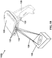
- FIG. 1B is an illustration of a handheld barcode scanner 100b.
- the barcode scanner 100b may include a main body 126 and a handle 128 .
- the handle 128 may include a scan trigger 130 .
- the main body 126 has a camera 132 located therein, whereby the camera 132 may capture images through a lens (not shown).
- a light source 134 may be located near the digital camera 132 .
- the barcode scanner 100b may also include a touch screen on its top surface that enables users to interact with the barcode scanner 100b disclosed herein in multiple ways.
- the screen itself may convey information to the user, such as current settings, current image scanned, a preview of the image to be captured, and previous images. Since the screen may be touch activated, a user may select icons, settings, or other items on the screen to interact with the digital barcode scanner 100b. Alternative user interfaces may be utilized, as well.
- the camera 132 may be configured to capture images in the front of the barcode scanner 100b. Digital images may be produced by the camera 132 .
- the lens of the camera 132 may be scratch resistant glass that both protects the internal camera 132 as well as resists scratches and other damage to its surface.
- the camera 132 may include a light source 134 , which may be configured with three different color light emitting diodes (LED), that emits different color light upon an object 136 while an image of the object 136 is being captured by the camera 132 .
- the three different color LEDs, or LED units, such as LED units 110 of FIG. 1A may be integrated within the barcode scanner 100b.
- a camera ready light may also be integrated into the front of the barcode scanner 100b.
- the camera ready light may emit a softer light so as to inform a user that an image is about to be captured.
- This camera ready or indicator light may use an amber colored LED light that emits light at a much lower intensity than the LED light source 134 that is used when an image is being captured.
- a processor unit (not shown) of the barcode scanner 100b may be in electrical communication with the light source 134 to generate drive signals for each of the three different color LEDs.
- the color LEDs may include one or more LEDs of red, blue, and green color.
- the processor unit may generate a first drive signal for the red and blue LEDs of the light source 134 having a first duty cycle, and a second drive signal for the green LED of the light source 134 having a second duty cycle, which is higher than the first duty cycle.
- the first drive signal may be applied to the red and blue LEDs of the light source 134 to cause the light source 134 to produce a beam of light from the red and blue LEDs having a first power value.
- the second drive signal may be applied to the green LED of the light source 134 to cause the light source 134 to produce a beam of light from the green LED having a second power value that is less than the first power value.
- the light beams combined from each LED of the light source 134 causes a white illumination beam 138 to be generated.
- First and second color LEDs may also be pulsing driven with high peak power simultaneously and synchronized with camera exposure time.
- Third color LEDs may also be wide pulsing or DC driven with very low peak power asynchronized with camera exposure time and optionally for visual purpose only, such as white; so that the third LEDs are very low power and low cost.
- the barcode scanner 100b may transmit captured image data to an external device, such as a processing unit through a wired or wireless data connection in order to read one or more machine readable indicia and identify features, such as watermarks on the object 136 in the image data.
- the wired connection can include a serial or universal serial bus (USB) port, whereby the barcode scanner 100b may be connected to another device via a serial or USB cable.
- the barcode scanner 100b may use a wireless connection.
- the barcode scanner 100b may include a wireless internet card that enables the scanner 100b to connect to a network over Wi-Fi® communications network, whereby data may be transferred between the barcode scanner 100b and an external device using transmission control protocol (TCP).
- TCP transmission control protocol
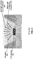
- FIG. 3A , 3B , and 3C are illustrations of illustrative of respective color light sources (collectively 300 ) of a barcode scanner system.
- a configuration of a first light source 300a of a barcode scanner system is shown.
- the first light source 300a may include one or more red color 302a , blue color 302b , and green color 302c LED units, respectively.
- the red and blue color LED units 302a , 302b may operate at a current of 1000 milliamps (mA) and a frequency of 80 Hertz (Hz), whereas the green color LED unit 302c may operate at a current of 2 mA in order produce beams of red, blue, and green colors which, when combined together, generate a white illumination beam.
- An image sensor of the barcode scanner system may capture an image of an object illuminated by the white illumination beam, and generate image data of the illuminated object. Image data may then be transmitted to a processing unit for processing in order to read one or more machine readable indicia, associated with the object as captured in the image data. It should be understood that the current and frequency values are illustrative, and other values may be utilized in imaging objects.
- the second light source 300b may include one or more red color 304a, a blue color 304b , and a green color 304c LED units, respectively.
- the red color LED unit 304a may operate at a current of 1000 mA and a frequency of 80 Hz
- the blue and green color LED units 304b , 304c may operate at a current of 2 mA in order produce beams of red, green, and blue colors which, when combined together, generate a white illumination beam.
- An image sensor of the barcode scanner system may capture an image of an object being illuminated by the white illumination beam, and generate image data of the illuminated object.
- the image data may then be transmitted to a processing unit for processing in order to read one or more machine readable indicia, associated with the object as captured in the image data.
- the third light source 300c may include one or more red color 306a and cyan color 306b LED units, respectively.
- the red color LED unit 306a may operate at a current of 1000 mA and a frequency of 80 Hz
- the cyan color LED unit 306b may operate at a current of 2 mA in order produce beams of red and cyan colors which, when combined together, generate a white illumination beam.
- An image sensor of the barcode scanner system may capture an image of an object being illuminated by the white illumination beam, and generate image data of the illuminated object.
- the image data may then be transmitted to a processing unit for processing in order to read one or more machine readable indicia, associated with the object as captured in the image data.
- the LEDs may be combined at printed circuit board level or at an LED packaging level for smaller size and easier color mixing since the LEDs are closer to each other.
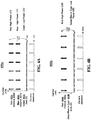
- FIG. 4A is an illustration of an illustrative graph 400a showing pulsing drive current waveforms of the LED units described in FIG. 3A is shown.
- Each of the three LED units may include one or more LEDs of a red color 402a , a blue color 402b , and a green color 402c , respectively.
- the red and blue color LED units 402a , 402b may be high power LEDs and driven to operate at a current of 1000 mA and a frequency of 80 Hz.
- the red color LED 402a may be 1Z2835AV66BFZIN2 by Brightek having a 660 nanometers (nm) wavelength and pulsing driven to operate at a peak current of 1000 mA and the blue color LED 402b may be STB0FS 12A by Seoul Semiconductor Co., Ltd. having a 450nm wavelength and pulsing driven to operate at a peak current of 1000 mA.
- the green color LED unit 402c may be a low power LED and be driven to operate at a DC current of 2 mA.
- the green color LED 402c may be QTLP650D4TR by Everlight or LG M670-J2L1-1-Z by Osram having a 570nm wavelength and driven to operate at a current of 2 mA.
- the red, blue, and green color beams produced by the LED units 402a , 402b , 402c generate a visual white illumination beam when combined using the drive current shown in FIG. 4A .
- FIG. 4B is an illustration (not according to the invention) of an illustrative graph 400b showing drive current waveforms of the LED units configuration described in FIGS. 3B and 3C is shown.
- the LED units may include LEDs of a red color 404a , and a LED unit of a green color, blue color, or a cyan color respectively 404b.
- the red color LED unit 404a may have high power LEDs, and operate at a pulsing peak current of 1000 mA and a frequency of 80 Hz.
- the green color, blue color, or cyan color LED unit 404b may have a low power LED and operate at a DC current of 2 mA.
- the red and green, blue, or cyan color beams produced by the LED units 404a , 404b generate a visual white illumination beam when combined using the drive current waveforms.
- FIG. 5 is an illustration of a graph 500a showing a typical watermark signal strength for a monochrome imager over wavelength distribution for a monochrome imager, such as a barcode scanner system.
- This graph 500a shows that the typical signal strength of a watermark extends over a wavelength range used to produce white light (i.e., monochrome imager) using only red and blue light to produce the useful signal on monochrome imager, as described herein.
- the graph indicates that for printed labels, low contrast by far red (e.g., about 720nm-730nm peak wavelength) illumination, but deep blue (e.g., about 405nm peak wavelength) illumination is sufficient to generate enough contrast to be readable by an image sensor for barcode labels, features or patterns, and watermarks, such as GS1 DW code, at the same time as visually the colors are at the end of the human visual curve.
- deep blue has the human perception of being dark and less disturbing.
- the value may be above or below the values by a percentage that still enables reading of the machine indicia (e.g., barcode, watermark, etc.).
- the graph further shows that for blue labels, deep blue illumination has low contrast, but far red illumination generates enough contrast for an image sensor to sense and read the watermark.
- green may further cause a reflectivity charge at a different wavelength.
- the use of green may be controlled outside of an imager exposure, which means that the imager does not image or see the green color while users are able to see the color.
- the graph 500a shows that the use a monochrome illumination source inclusive of two colors (i.e., red and blue) at certain power levels by applying certain duty cycles, for example, enables sensing of a watermark.
- colors that operate at different wavelengths and with different power levels produced by different duty cycles and produce a reflectivity charge that may be sensed by an image sensor may also be utilized.
- FIG. 6 is a flow diagram of an illustrative process 600 for reading image data.
- a first color light source signal is generated based on inputs having a first duty cycle.
- the first color light source may include a red color LED.
- the first color light source may include a blue color LED.
- the first color light source may include a combination of red color and blue color LEDs.
- a second color light source signal is generated by the processor unit and/or the LED driver circuit based on inputs received from the processor unit having a second duty cycle that is greater than the first duty cycle.
- the second color light source may include a green color LED.
- the second color light source may include a cyan color LED.
- the second color light source may include a blue color LED.
- the first color light source drive signal is applied to a first color light source to cause the first color light source to produce a light beam of a first color at a first power level.
- the second color light source drive signal is applied to a second color light source to cause the second color light source to produce a light beam of a second color at a second power level that is lower than the first power level.
- the light beams combined from the first and second color light sources may cause a white illumination beam to be generated.
- a camera captures an image of an object illuminated by the white illumination beam, and generate image data of the object.
- the camera may transmit the image data to a processing unit through a wired or wireless data connection, where the processing unit processes the image data in order to read a machine readable indicia, watermark, and/or object features in the image data.
- FIG. 7 is a flow diagram of an illustrative process 700 for reading image data.
- a first color light source signal is generated based on inputs having a first duty cycle.
- the first color light source may include a red color LED.
- a second color light source signal is generated based on inputs having the first duty cycle.
- the second color light source may include a blue color LED.
- the first color light source drive signal is applied to a first color light source to cause the first color light source to produce a light beam of a first color at a first power level.
- the second color light source drive signals applied to a second color light source to cause the second color light source to produce a light beam of a second color at the first power level.
- the light beams combined from the first and second color light sources cause a white illumination beam to be generated.
- a camera captures an image of an object illuminated by the white illumination beam and generate an image data of the object.
- the camera may transmit the image data to a processing unit through a wired or wireless data connection, where the processing unit may process the image data in order to read a machine readable indicia in the image data.
- the processing unit may be alternatively positioned within the scanner.
- process flow diagrams are provided merely as illustrative examples and are not intended to require or imply that the steps of the various embodiments must be performed in the order presented. As will be appreciated by one of skill in the art the steps in the foregoing embodiments may be performed in any order. Words such as “then,” “next,” etc. are not intended to limit the order of the steps; these words are simply used to guide the reader through the description of the methods.
- process flow diagrams may describe the operations as a sequential process, many of the operations can be performed in parallel or concurrently. In addition, the order of the operations may be rearranged.
- a process may correspond to a method, a function, a procedure, a subroutine, a subprogram, etc. When a process corresponds to a function, its termination may correspond to a return of the function to the calling function or the main function.
- Embodiments implemented in computer software may be implemented in software, firmware, middleware, microcode, hardware description languages, or any combination thereof.
- a code segment or machine-executable instructions may represent a procedure, a function, a subprogram, a program, a routine, a subroutine, a module, a software package, a class, or any combination of instructions, data structures, or program statements.
- a code segment may be coupled to another code segment or a hardware circuit by passing and/or receiving information, data, arguments, parameters, or memory contents.
- Information, arguments, parameters, data, etc. may be passed, forwarded, or transmitted via any suitable means including memory sharing, message passing, token passing, network transmission, etc.
- the functions When implemented in software, the functions may be stored as one or more instructions or code on a non-transitory computer-readable or processor-readable storage medium.
- the steps of a method or algorithm disclosed herein may be embodied in a processor- executable software module which may reside on a computer-readable or processor-readable storage medium.
- a non-transitory computer-readable or processor-readable media includes both computer storage media and tangible storage media that facilitate transfer of a computer program from one place to another.
- a non-transitory processor-readable storage media may be any available media that may be accessed by a computer.
- non-transitory processor-readable media may comprise RAM, ROM, EEPROM, CD-ROM or other optical disk storage, magnetic disk storage or other magnetic storage devices, or any other tangible storage medium that may be used to store desired program code in the form of instructions or data structures and that may be accessed by a computer or processor.
- Disk and disc include compact disc (CD), laser disc, optical disc, digital versatile disc (DVD), floppy disk, and Blu-ray disc where disks usually reproduce data magnetically, while discs reproduce data optically with lasers. Combinations of the above should also be included within the scope of computer-readable media.
- the operations of a method or algorithm may reside as one or any combination or set of codes and/or instructions on a non- transitory processor-readable medium and/or computer-readable medium, which may be incorporated into a computer program product.
Landscapes
- Physics & Mathematics (AREA)
- Engineering & Computer Science (AREA)
- Electromagnetism (AREA)
- Theoretical Computer Science (AREA)
- General Physics & Mathematics (AREA)
- General Health & Medical Sciences (AREA)
- Artificial Intelligence (AREA)
- Computer Vision & Pattern Recognition (AREA)
- Toxicology (AREA)
- Health & Medical Sciences (AREA)
- Quality & Reliability (AREA)
- Facsimile Scanning Arrangements (AREA)
- Image Input (AREA)
- Circuit Arrangement For Electric Light Sources In General (AREA)
Claims (7)
- Strichcode-Scannersystem, umfassend:mindestens eine erste und eine zweite Farb-LED-Lichtquelle (110a, 110b), wobeidie erste Farb-LED-Lichtquelle (110a) dazu konfiguriert ist, Licht mit einer ersten Wellenlänge zu erzeugen;die zweite Farb-LED-Lichtquelle (110b) dazu konfiguriert ist, Licht mit einer zweiten Wellenlänge zu erzeugen; wobei das System ferner umfasst:eine Steuerelektronik (112), die in elektrischer Verbindung mit der ersten Farb-LED-Lichtquelle (110a) und der zweiten Farb-LED-Lichtquelle (110b) steht, wobei die Steuerelektronik (112) umfasst:eine Treiberschaltung (116), die konfiguriert ist zum Erzeugen von:einem ersten Farb-LED-Lichtquellen-Treibersignal (117a), das ein erstes Tastverhältnis aufweist und das bewirkt, wenn es an die erste Farb-LED-Lichtquelle (110a) angelegt wird, dass die erste Farb-LED-Lichtquelle (110a) einen Lichtstrahl mit einem ersten Leistungspegel erzeugt, undeinem zweiten Farb-LED-Lichtquellen-Treibersignal (117b), das ein zweites Tastverhältnis aufweist und das bewirkt, wenn es an die zweite Farb-LED-Lichtquelle (110b) angelegt wird, dass die zweite Farb-LED-Lichtquelle (110b) einen Lichtstrahl mit einem zweiten Leistungspegel erzeugt, und wenn das erste und das zweite Farb-LED-Lichtquellen-Treibersignal (117a, 117b) jeweils an die erste und die zweite Farb-LED-Lichtquelle (110a, 110b) angelegt werden, bewirken die Lichtstrahlen, die von der ersten und der zweiten Farb-LED-Lichtquelle (110a, 110b) kombiniert werden, dass ein weißer Beleuchtungsstrahls (124, 138) erzeugt wird;einen Bildsensor (120), der dazu konfiguriert ist, ein Bild zu erfassen und Bilddaten (106) eines Objekts (104, 136), das von dem weißen Beleuchtungsstrahl (124, 138) beleuchtet wird, zu erzeugen; undeine Verarbeitungseinheit, die dazu konfiguriert ist, eine oder mehrere maschinenlesbare Zeichen (125) des Objekts (104, 136) in den Bilddaten (106) zu lesen;gekennzeichnet durcheinen Lichtsensor (122), um einen Umgebungslichtpegel zu erfassen; wobeidie Steuerelektronik (112) ferner dazu konfiguriert ist, ein für den Umgebungslichtpegel repräsentatives Signal (123) von dem Lichtsensor (122) zu empfangen, um die Intensität des von der ersten und der zweiten Farb-LED-Lichtquelle (110a, 110b) emittierten Lichts automatisch einzustellen, um die visuell weiße Beleuchtung basierend auf dem Umgebungslichtpegel zu erzeugen, wobei die automatische Einstellung der Intensität des Lichts, das von der ersten und der zweiten Farb-LED-Lichtquelle (110a, 110b) emittiert wird, durch die Treiberschaltung (116) erreicht wird, die eine Spannung und/oder einen Strom und/oder eine Zeitmodulation und/oder ein Tastverhältnis ändert, um die Intensität des Lichts zu steuern, das von der ersten und der zweiten Farb-LED-Lichtquelle (110a, 110b) basierend auf Signalen emittiert wird, die von dem Lichtsensor (122) erhalten werden.
- Barcode-Scannersystem nach Anspruch 1, wobei das erste Tastverhältnis und das zweite Tastverhältnis gleich sind und der erste Leistungspegel und der zweite Leistungspegel gleich sind.
- Barcode-Scannersystem nach Anspruch 1 oder 2, wobei die erste Farb-LED-Lichtquelle (110a) eine rote Farb-LED-Lichtquelle ist.
- Barcode-Scannersystem nach Anspruch 3, wobei die rote Farb-LED-Lichtquelle eine Spitzenwellenlänge von ungefähr 730 Nanometern (nm) hat.
- Barcode-Scannersystem nach Anspruch 4, wobei die zweite Farb-LED-Lichtquelle (110b) eine blaue Farb-LED-Lichtquelle ist.
- Barcode-Scannersystem nach Anspruch 5, wobei die blaue Farb-LED-Lichtquelle eine Spitzenwellenlänge von 405 Nanometern (nm) hat.
- Verfahren zum Abbilden von Objekten (104, 136) unter Verwendung eines Barcode-Scannersystems nach einem der vorhergehenden Ansprüche 2 bis 6, wobei das Verfahren umfasst:Erzeugen des ersten Farb-LED-Lichtquellen-Treibersignals (117a), das das erste Tastverhältnis aufweist;Erzeugen des zweiten Farb-LED-Lichtquellen-Treibersignals (117b), das das zweite Tastverhältnis aufweist, wobei das erste Tastverhältnis und das zweite Tastverhältnis das gleiche sind;Kombinieren, als Reaktion auf das Anlegen des ersten und zweiten Farb-LED-Lichtquellen-Treibersignals (117a, 117b) an die erste beziehungsweise zweite Farb-LED-Lichtquelle (110a, 110b), von Lichtstrahlen, die von der ersten und zweiten Farb-LED-Lichtquelle (110a, 110b) erzeugt werden, um den weißen Beleuchtungsstrahl (124, 138) zu erzeugen;Erzeugen von Bilddaten (106) des Objekts (104, 136), die die maschinenlesbaren Zeichen (125) umfassen, die von dem weißen Beleuchtungsstrahl (124, 138) beleuchtet werden; undLesen der maschinenlesbaren Zeichen (125) des Objekts (104, 136) in den Bilddaten (106);Erfassen des Umgebungslichtpegels durch den Lichtsensor; undEmpfangen des für den Umgebungslichtpegel repräsentativen Signals (123) von dem Lichtsensor (123) und automatisches Einstellen der Intensität des Lichts, das von der ersten und zweiten Farb-LED-Lichtquelle (110a, 110b) emittiert wird, um die visuell weiße Beleuchtung basierend auf dem Umgebungslichtpegel zu erzeugen.
Applications Claiming Priority (2)
| Application Number | Priority Date | Filing Date | Title |
|---|---|---|---|
| US15/389,090 US10268860B2 (en) | 2016-12-22 | 2016-12-22 | White illumination for barcode scanners with improved power efficiency and cost |
| PCT/US2017/068282 WO2018119430A1 (en) | 2016-12-22 | 2017-12-22 | White illumination for barcode scanners with improved power efficiency and cost |
Publications (3)
| Publication Number | Publication Date |
|---|---|
| EP3559855A1 EP3559855A1 (de) | 2019-10-30 |
| EP3559855A4 EP3559855A4 (de) | 2020-07-15 |
| EP3559855B1 true EP3559855B1 (de) | 2021-11-03 |
Family
ID=62627763
Family Applications (1)
| Application Number | Title | Priority Date | Filing Date |
|---|---|---|---|
| EP17883240.8A Active EP3559855B1 (de) | 2016-12-22 | 2017-12-22 | Weisse beleuchtung für strichcode-scanner mit verbesserter leistungseffizienz und kosten |
Country Status (3)
| Country | Link |
|---|---|
| US (1) | US10268860B2 (de) |
| EP (1) | EP3559855B1 (de) |
| WO (1) | WO2018119430A1 (de) |
Cited By (1)
| Publication number | Priority date | Publication date | Assignee | Title |
|---|---|---|---|---|
| EP4377834A2 (de) * | 2021-07-31 | 2024-06-05 | Cognex Corporation | Maschinensichtsystem und verfahren mit multispektraler lichtanordnung |
Families Citing this family (8)
| Publication number | Priority date | Publication date | Assignee | Title |
|---|---|---|---|---|
| US10453162B2 (en) * | 2016-04-22 | 2019-10-22 | Datalogic Usa, Inc. | Monochrome imaging of digital watermarks in white light |
| WO2019032590A1 (en) | 2017-08-09 | 2019-02-14 | The Board Of Trustees Of The Leland Stanford Junior University | INTERACTIVE BIOMETRIC TOUCH SCANNER |
| CN110598496A (zh) * | 2019-09-10 | 2019-12-20 | 北京京东振世信息技术有限公司 | 一种扫描设备、方法、装置及其存储介质 |
| US11176342B2 (en) | 2020-01-15 | 2021-11-16 | Datalogic Usa Inc. | Produce or item recognition by hybrid 3D camera and/or multi-spectrum illumination |
| WO2022020737A1 (en) * | 2020-07-24 | 2022-01-27 | The Coca-Cola Company | Systems and methods for associating vessels with user accounts |
| JP7830972B2 (ja) * | 2022-02-03 | 2026-03-17 | カシオ計算機株式会社 | 端末装置、制御方法及びプログラム |
| US12550045B2 (en) * | 2022-04-08 | 2026-02-10 | Qualcomm Incorporated | Optical reference signal based TRP detection |
| US12556826B2 (en) * | 2022-07-29 | 2026-02-17 | Zebra Technologies Corporation | Selective use of illumination color in scanning and industrial scanning applications |
Family Cites Families (12)
| Publication number | Priority date | Publication date | Assignee | Title |
|---|---|---|---|---|
| US20060237636A1 (en) * | 2003-06-23 | 2006-10-26 | Advanced Optical Technologies, Llc | Integrating chamber LED lighting with pulse amplitude modulation to set color and/or intensity of output |
| EP1612569A3 (de) | 2004-06-30 | 2006-02-08 | Omron Corporation | Verfahren und Vorrichtung zur Substrat-Oberflächeninspektion mittels eines vielfarbigen Lichtdemissionssystems |
| US7646029B2 (en) * | 2004-07-08 | 2010-01-12 | Philips Solid-State Lighting Solutions, Inc. | LED package methods and systems |
| US7568628B2 (en) | 2005-03-11 | 2009-08-04 | Hand Held Products, Inc. | Bar code reading device with global electronic shutter control |
| US7433026B2 (en) * | 2005-12-20 | 2008-10-07 | Cytyc Corporation | Microscope with LED illumination source |
| JP2007286793A (ja) | 2006-04-14 | 2007-11-01 | Denso Wave Inc | 情報コード読取装置 |
| WO2007121486A2 (en) | 2006-04-18 | 2007-10-25 | Lamina Lighting, Inc. | Optical devices for controlled color mixing |
| JP4306741B2 (ja) | 2006-07-20 | 2009-08-05 | 株式会社デンソーウェーブ | 光学情報読取装置 |
| US9749607B2 (en) * | 2009-07-16 | 2017-08-29 | Digimarc Corporation | Coordinated illumination and image signal capture for enhanced signal detection |
| US8632011B2 (en) * | 2011-01-18 | 2014-01-21 | Datalogic ADC, Inc. | Systems and methods for illuminating a scan volume of an optical code reader |
| JP5533714B2 (ja) | 2011-02-07 | 2014-06-25 | 株式会社デンソーウェーブ | 光学情報読み取り装置 |
| WO2013074978A1 (en) | 2011-11-17 | 2013-05-23 | Datalogic ADC, Inc. | Systems and methods for reading color optical codes |
-
2016
- 2016-12-22 US US15/389,090 patent/US10268860B2/en active Active
-
2017
- 2017-12-22 EP EP17883240.8A patent/EP3559855B1/de active Active
- 2017-12-22 WO PCT/US2017/068282 patent/WO2018119430A1/en not_active Ceased
Cited By (2)
| Publication number | Priority date | Publication date | Assignee | Title |
|---|---|---|---|---|
| EP4377834A2 (de) * | 2021-07-31 | 2024-06-05 | Cognex Corporation | Maschinensichtsystem und verfahren mit multispektraler lichtanordnung |
| EP4377834B1 (de) * | 2021-07-31 | 2025-12-10 | Cognex Corporation | Maschinensichtsystem mit multispektraler lichtanordnung |
Also Published As
| Publication number | Publication date |
|---|---|
| EP3559855A4 (de) | 2020-07-15 |
| WO2018119430A1 (en) | 2018-06-28 |
| US20180181786A1 (en) | 2018-06-28 |
| EP3559855A1 (de) | 2019-10-30 |
| US10268860B2 (en) | 2019-04-23 |
Similar Documents
| Publication | Publication Date | Title |
|---|---|---|
| EP3559855B1 (de) | Weisse beleuchtung für strichcode-scanner mit verbesserter leistungseffizienz und kosten | |
| US11386281B2 (en) | Coordinated illumination and image signal capture for enhanced signal detection | |
| US9112606B2 (en) | Method and apparatus for transmitting and receiving data using visible light communication | |
| EP2752787B1 (de) | Systeme und Verfahren zum Lesen optischer Codes anhand eines Farbbildgebers | |
| US8752768B2 (en) | Systems and methods for reading color optical codes | |
| US8800873B2 (en) | Apparatus for optically reading information stored in graphic symbol | |
| US12167147B2 (en) | Systems and methods for operating an imaging device | |
| JPWO2009054363A1 (ja) | 情報コード | |
| US9836679B2 (en) | Controlled and multi-color scanner illumination | |
| EP2519912B1 (de) | Tragbare vorrichtung und verfahren zum lesen von verschlüsselten informationen | |
| EP3435557B1 (de) | Unterscheidungsverfahren und kommunikationssystem | |
| JP2026027309A (ja) | マルチアパーチャ光学系アセンブリを備えたマシンビジョンシステム及び方法 | |
| EP4604009A1 (de) | Datenlesesysteme mit mehreren bildverarbeitungsbetriebsarten | |
| CN203191996U (zh) | 具有激光对位指示的条码扫描器 | |
| KR20120067268A (ko) | 가시광 무선 통신을 이용한 송수신 장치 및 방법 | |
| CN107248242B (zh) | 水印启用扫描 | |
| CN215526678U (zh) | 一种智能照明条码扫描器 | |
| JP3668752B2 (ja) | 識別コードの読取装置および表示用カラーディスプレイ | |
| JP4082321B2 (ja) | 光学的情報読取装置 | |
| JP7567383B2 (ja) | スキャナー、画像データの生産方法、制御プログラム | |
| JP7430554B2 (ja) | 光学式情報読取装置、光学式情報読取方法、光学式情報読取プログラム及びコンピュータで読取可能な記録媒体並びに記録した機器 | |
| JP2004118491A (ja) | 印刷の読取方法 |
Legal Events
| Date | Code | Title | Description |
|---|---|---|---|
| STAA | Information on the status of an ep patent application or granted ep patent |
Free format text: STATUS: THE INTERNATIONAL PUBLICATION HAS BEEN MADE |
|
| PUAI | Public reference made under article 153(3) epc to a published international application that has entered the european phase |
Free format text: ORIGINAL CODE: 0009012 |
|
| STAA | Information on the status of an ep patent application or granted ep patent |
Free format text: STATUS: REQUEST FOR EXAMINATION WAS MADE |
|
| 17P | Request for examination filed |
Effective date: 20190719 |
|
| AK | Designated contracting states |
Kind code of ref document: A1 Designated state(s): AL AT BE BG CH CY CZ DE DK EE ES FI FR GB GR HR HU IE IS IT LI LT LU LV MC MK MT NL NO PL PT RO RS SE SI SK SM TR |
|
| AX | Request for extension of the european patent |
Extension state: BA ME |
|
| DAV | Request for validation of the european patent (deleted) | ||
| DAX | Request for extension of the european patent (deleted) | ||
| A4 | Supplementary search report drawn up and despatched |
Effective date: 20200616 |
|
| RIC1 | Information provided on ipc code assigned before grant |
Ipc: G06K 7/14 20060101AFI20200609BHEP Ipc: G06K 19/06 20060101ALI20200609BHEP Ipc: G06K 7/10 20060101ALI20200609BHEP |
|
| GRAP | Despatch of communication of intention to grant a patent |
Free format text: ORIGINAL CODE: EPIDOSNIGR1 |
|
| STAA | Information on the status of an ep patent application or granted ep patent |
Free format text: STATUS: GRANT OF PATENT IS INTENDED |
|
| INTG | Intention to grant announced |
Effective date: 20210521 |
|
| GRAS | Grant fee paid |
Free format text: ORIGINAL CODE: EPIDOSNIGR3 |
|
| GRAA | (expected) grant |
Free format text: ORIGINAL CODE: 0009210 |
|
| STAA | Information on the status of an ep patent application or granted ep patent |
Free format text: STATUS: THE PATENT HAS BEEN GRANTED |
|
| AK | Designated contracting states |
Kind code of ref document: B1 Designated state(s): AL AT BE BG CH CY CZ DE DK EE ES FI FR GB GR HR HU IE IS IT LI LT LU LV MC MK MT NL NO PL PT RO RS SE SI SK SM TR |
|
| REG | Reference to a national code |
Ref country code: GB Ref legal event code: FG4D |
|
| REG | Reference to a national code |
Ref country code: AT Ref legal event code: REF Ref document number: 1444627 Country of ref document: AT Kind code of ref document: T Effective date: 20211115 Ref country code: CH Ref legal event code: EP |
|
| REG | Reference to a national code |
Ref country code: IE Ref legal event code: FG4D |
|
| REG | Reference to a national code |
Ref country code: DE Ref legal event code: R096 Ref document number: 602017048915 Country of ref document: DE |
|
| REG | Reference to a national code |
Ref country code: LT Ref legal event code: MG9D |
|
| REG | Reference to a national code |
Ref country code: NL Ref legal event code: MP Effective date: 20211103 |
|
| REG | Reference to a national code |
Ref country code: AT Ref legal event code: MK05 Ref document number: 1444627 Country of ref document: AT Kind code of ref document: T Effective date: 20211103 |
|
| PG25 | Lapsed in a contracting state [announced via postgrant information from national office to epo] |
Ref country code: RS Free format text: LAPSE BECAUSE OF FAILURE TO SUBMIT A TRANSLATION OF THE DESCRIPTION OR TO PAY THE FEE WITHIN THE PRESCRIBED TIME-LIMIT Effective date: 20211103 Ref country code: LT Free format text: LAPSE BECAUSE OF FAILURE TO SUBMIT A TRANSLATION OF THE DESCRIPTION OR TO PAY THE FEE WITHIN THE PRESCRIBED TIME-LIMIT Effective date: 20211103 Ref country code: FI Free format text: LAPSE BECAUSE OF FAILURE TO SUBMIT A TRANSLATION OF THE DESCRIPTION OR TO PAY THE FEE WITHIN THE PRESCRIBED TIME-LIMIT Effective date: 20211103 Ref country code: BG Free format text: LAPSE BECAUSE OF FAILURE TO SUBMIT A TRANSLATION OF THE DESCRIPTION OR TO PAY THE FEE WITHIN THE PRESCRIBED TIME-LIMIT Effective date: 20220203 Ref country code: AT Free format text: LAPSE BECAUSE OF FAILURE TO SUBMIT A TRANSLATION OF THE DESCRIPTION OR TO PAY THE FEE WITHIN THE PRESCRIBED TIME-LIMIT Effective date: 20211103 |
|
| PG25 | Lapsed in a contracting state [announced via postgrant information from national office to epo] |
Ref country code: IS Free format text: LAPSE BECAUSE OF FAILURE TO SUBMIT A TRANSLATION OF THE DESCRIPTION OR TO PAY THE FEE WITHIN THE PRESCRIBED TIME-LIMIT Effective date: 20220303 Ref country code: SE Free format text: LAPSE BECAUSE OF FAILURE TO SUBMIT A TRANSLATION OF THE DESCRIPTION OR TO PAY THE FEE WITHIN THE PRESCRIBED TIME-LIMIT Effective date: 20211103 Ref country code: PT Free format text: LAPSE BECAUSE OF FAILURE TO SUBMIT A TRANSLATION OF THE DESCRIPTION OR TO PAY THE FEE WITHIN THE PRESCRIBED TIME-LIMIT Effective date: 20220303 Ref country code: PL Free format text: LAPSE BECAUSE OF FAILURE TO SUBMIT A TRANSLATION OF THE DESCRIPTION OR TO PAY THE FEE WITHIN THE PRESCRIBED TIME-LIMIT Effective date: 20211103 Ref country code: NO Free format text: LAPSE BECAUSE OF FAILURE TO SUBMIT A TRANSLATION OF THE DESCRIPTION OR TO PAY THE FEE WITHIN THE PRESCRIBED TIME-LIMIT Effective date: 20220203 Ref country code: NL Free format text: LAPSE BECAUSE OF FAILURE TO SUBMIT A TRANSLATION OF THE DESCRIPTION OR TO PAY THE FEE WITHIN THE PRESCRIBED TIME-LIMIT Effective date: 20211103 Ref country code: LV Free format text: LAPSE BECAUSE OF FAILURE TO SUBMIT A TRANSLATION OF THE DESCRIPTION OR TO PAY THE FEE WITHIN THE PRESCRIBED TIME-LIMIT Effective date: 20211103 Ref country code: HR Free format text: LAPSE BECAUSE OF FAILURE TO SUBMIT A TRANSLATION OF THE DESCRIPTION OR TO PAY THE FEE WITHIN THE PRESCRIBED TIME-LIMIT Effective date: 20211103 Ref country code: GR Free format text: LAPSE BECAUSE OF FAILURE TO SUBMIT A TRANSLATION OF THE DESCRIPTION OR TO PAY THE FEE WITHIN THE PRESCRIBED TIME-LIMIT Effective date: 20220204 Ref country code: ES Free format text: LAPSE BECAUSE OF FAILURE TO SUBMIT A TRANSLATION OF THE DESCRIPTION OR TO PAY THE FEE WITHIN THE PRESCRIBED TIME-LIMIT Effective date: 20211103 |
|
| PG25 | Lapsed in a contracting state [announced via postgrant information from national office to epo] |
Ref country code: SM Free format text: LAPSE BECAUSE OF FAILURE TO SUBMIT A TRANSLATION OF THE DESCRIPTION OR TO PAY THE FEE WITHIN THE PRESCRIBED TIME-LIMIT Effective date: 20211103 Ref country code: SK Free format text: LAPSE BECAUSE OF FAILURE TO SUBMIT A TRANSLATION OF THE DESCRIPTION OR TO PAY THE FEE WITHIN THE PRESCRIBED TIME-LIMIT Effective date: 20211103 Ref country code: RO Free format text: LAPSE BECAUSE OF FAILURE TO SUBMIT A TRANSLATION OF THE DESCRIPTION OR TO PAY THE FEE WITHIN THE PRESCRIBED TIME-LIMIT Effective date: 20211103 Ref country code: EE Free format text: LAPSE BECAUSE OF FAILURE TO SUBMIT A TRANSLATION OF THE DESCRIPTION OR TO PAY THE FEE WITHIN THE PRESCRIBED TIME-LIMIT Effective date: 20211103 Ref country code: DK Free format text: LAPSE BECAUSE OF FAILURE TO SUBMIT A TRANSLATION OF THE DESCRIPTION OR TO PAY THE FEE WITHIN THE PRESCRIBED TIME-LIMIT Effective date: 20211103 Ref country code: CZ Free format text: LAPSE BECAUSE OF FAILURE TO SUBMIT A TRANSLATION OF THE DESCRIPTION OR TO PAY THE FEE WITHIN THE PRESCRIBED TIME-LIMIT Effective date: 20211103 |
|
| REG | Reference to a national code |
Ref country code: CH Ref legal event code: PL |
|
| REG | Reference to a national code |
Ref country code: DE Ref legal event code: R097 Ref document number: 602017048915 Country of ref document: DE |
|
| PG25 | Lapsed in a contracting state [announced via postgrant information from national office to epo] |
Ref country code: MC Free format text: LAPSE BECAUSE OF FAILURE TO SUBMIT A TRANSLATION OF THE DESCRIPTION OR TO PAY THE FEE WITHIN THE PRESCRIBED TIME-LIMIT Effective date: 20211103 |
|
| PLBE | No opposition filed within time limit |
Free format text: ORIGINAL CODE: 0009261 |
|
| STAA | Information on the status of an ep patent application or granted ep patent |
Free format text: STATUS: NO OPPOSITION FILED WITHIN TIME LIMIT |
|
| REG | Reference to a national code |
Ref country code: BE Ref legal event code: MM Effective date: 20211231 |
|
| 26N | No opposition filed |
Effective date: 20220804 |
|
| GBPC | Gb: european patent ceased through non-payment of renewal fee |
Effective date: 20220203 |
|
| PG25 | Lapsed in a contracting state [announced via postgrant information from national office to epo] |
Ref country code: LU Free format text: LAPSE BECAUSE OF NON-PAYMENT OF DUE FEES Effective date: 20211222 Ref country code: IE Free format text: LAPSE BECAUSE OF NON-PAYMENT OF DUE FEES Effective date: 20211222 Ref country code: AL Free format text: LAPSE BECAUSE OF FAILURE TO SUBMIT A TRANSLATION OF THE DESCRIPTION OR TO PAY THE FEE WITHIN THE PRESCRIBED TIME-LIMIT Effective date: 20211103 |
|
| PG25 | Lapsed in a contracting state [announced via postgrant information from national office to epo] |
Ref country code: SI Free format text: LAPSE BECAUSE OF FAILURE TO SUBMIT A TRANSLATION OF THE DESCRIPTION OR TO PAY THE FEE WITHIN THE PRESCRIBED TIME-LIMIT Effective date: 20211103 Ref country code: FR Free format text: LAPSE BECAUSE OF NON-PAYMENT OF DUE FEES Effective date: 20220103 Ref country code: BE Free format text: LAPSE BECAUSE OF NON-PAYMENT OF DUE FEES Effective date: 20211231 |
|
| PG25 | Lapsed in a contracting state [announced via postgrant information from national office to epo] |
Ref country code: LI Free format text: LAPSE BECAUSE OF NON-PAYMENT OF DUE FEES Effective date: 20211231 Ref country code: CH Free format text: LAPSE BECAUSE OF NON-PAYMENT OF DUE FEES Effective date: 20211231 |
|
| PG25 | Lapsed in a contracting state [announced via postgrant information from national office to epo] |
Ref country code: GB Free format text: LAPSE BECAUSE OF NON-PAYMENT OF DUE FEES Effective date: 20220203 |
|
| PG25 | Lapsed in a contracting state [announced via postgrant information from national office to epo] |
Ref country code: CY Free format text: LAPSE BECAUSE OF FAILURE TO SUBMIT A TRANSLATION OF THE DESCRIPTION OR TO PAY THE FEE WITHIN THE PRESCRIBED TIME-LIMIT Effective date: 20211103 |
|
| P01 | Opt-out of the competence of the unified patent court (upc) registered |
Effective date: 20230527 |
|
| PG25 | Lapsed in a contracting state [announced via postgrant information from national office to epo] |
Ref country code: HU Free format text: LAPSE BECAUSE OF FAILURE TO SUBMIT A TRANSLATION OF THE DESCRIPTION OR TO PAY THE FEE WITHIN THE PRESCRIBED TIME-LIMIT; INVALID AB INITIO Effective date: 20171222 |
|
| PG25 | Lapsed in a contracting state [announced via postgrant information from national office to epo] |
Ref country code: MK Free format text: LAPSE BECAUSE OF FAILURE TO SUBMIT A TRANSLATION OF THE DESCRIPTION OR TO PAY THE FEE WITHIN THE PRESCRIBED TIME-LIMIT Effective date: 20211103 |
|
| PG25 | Lapsed in a contracting state [announced via postgrant information from national office to epo] |
Ref country code: MT Free format text: LAPSE BECAUSE OF FAILURE TO SUBMIT A TRANSLATION OF THE DESCRIPTION OR TO PAY THE FEE WITHIN THE PRESCRIBED TIME-LIMIT Effective date: 20211103 |
|
| PG25 | Lapsed in a contracting state [announced via postgrant information from national office to epo] |
Ref country code: TR Free format text: LAPSE BECAUSE OF FAILURE TO SUBMIT A TRANSLATION OF THE DESCRIPTION OR TO PAY THE FEE WITHIN THE PRESCRIBED TIME-LIMIT Effective date: 20211103 |
|
| PGFP | Annual fee paid to national office [announced via postgrant information from national office to epo] |
Ref country code: DE Payment date: 20251211 Year of fee payment: 9 |
|
| PGFP | Annual fee paid to national office [announced via postgrant information from national office to epo] |
Ref country code: IT Payment date: 20251223 Year of fee payment: 9 |