EP3560313A1 - Dispositif de fixation d'une tête de coupe, appareil de travail portatif doté un dispositif de fixation d'une tête de coupe - Google Patents
Dispositif de fixation d'une tête de coupe, appareil de travail portatif doté un dispositif de fixation d'une tête de coupe Download PDFInfo
- Publication number
- EP3560313A1 EP3560313A1 EP18169970.3A EP18169970A EP3560313A1 EP 3560313 A1 EP3560313 A1 EP 3560313A1 EP 18169970 A EP18169970 A EP 18169970A EP 3560313 A1 EP3560313 A1 EP 3560313A1
- Authority
- EP
- European Patent Office
- Prior art keywords
- hood
- cutting head
- output shaft
- rotation
- axis
- Prior art date
- Legal status (The legal status is an assumption and is not a legal conclusion. Google has not performed a legal analysis and makes no representation as to the accuracy of the status listed.)
- Granted
Links
Images



Classifications
-
- A—HUMAN NECESSITIES
- A01—AGRICULTURE; FORESTRY; ANIMAL HUSBANDRY; HUNTING; TRAPPING; FISHING
- A01D—HARVESTING; MOWING
- A01D34/00—Mowers; Mowing apparatus of harvesters
- A01D34/835—Mowers; Mowing apparatus of harvesters specially adapted for particular purposes
- A01D34/90—Mowers; Mowing apparatus of harvesters specially adapted for particular purposes for carrying by the operator
-
- A—HUMAN NECESSITIES
- A01—AGRICULTURE; FORESTRY; ANIMAL HUSBANDRY; HUNTING; TRAPPING; FISHING
- A01D—HARVESTING; MOWING
- A01D34/00—Mowers; Mowing apparatus of harvesters
- A01D34/01—Mowers; Mowing apparatus of harvesters characterised by features relating to the type of cutting apparatus
- A01D34/412—Mowers; Mowing apparatus of harvesters characterised by features relating to the type of cutting apparatus having rotating cutters
- A01D34/416—Flexible line cutters
-
- A—HUMAN NECESSITIES
- A01—AGRICULTURE; FORESTRY; ANIMAL HUSBANDRY; HUNTING; TRAPPING; FISHING
- A01D—HARVESTING; MOWING
- A01D34/00—Mowers; Mowing apparatus of harvesters
- A01D34/01—Mowers; Mowing apparatus of harvesters characterised by features relating to the type of cutting apparatus
- A01D34/412—Mowers; Mowing apparatus of harvesters characterised by features relating to the type of cutting apparatus having rotating cutters
- A01D34/416—Flexible line cutters
- A01D34/4165—Mounting of the cutter head
-
- A—HUMAN NECESSITIES
- A01—AGRICULTURE; FORESTRY; ANIMAL HUSBANDRY; HUNTING; TRAPPING; FISHING
- A01D—HARVESTING; MOWING
- A01D34/00—Mowers; Mowing apparatus of harvesters
- A01D34/01—Mowers; Mowing apparatus of harvesters characterised by features relating to the type of cutting apparatus
- A01D34/412—Mowers; Mowing apparatus of harvesters characterised by features relating to the type of cutting apparatus having rotating cutters
- A01D34/63—Mowers; Mowing apparatus of harvesters characterised by features relating to the type of cutting apparatus having rotating cutters having cutters rotating about a vertical axis
-
- A—HUMAN NECESSITIES
- A01—AGRICULTURE; FORESTRY; ANIMAL HUSBANDRY; HUNTING; TRAPPING; FISHING
- A01D—HARVESTING; MOWING
- A01D34/00—Mowers; Mowing apparatus of harvesters
- A01D34/01—Mowers; Mowing apparatus of harvesters characterised by features relating to the type of cutting apparatus
- A01D34/412—Mowers; Mowing apparatus of harvesters characterised by features relating to the type of cutting apparatus having rotating cutters
- A01D34/63—Mowers; Mowing apparatus of harvesters characterised by features relating to the type of cutting apparatus having rotating cutters having cutters rotating about a vertical axis
- A01D34/67—Mowers; Mowing apparatus of harvesters characterised by features relating to the type of cutting apparatus having rotating cutters having cutters rotating about a vertical axis hand-guided by a walking operator
-
- A—HUMAN NECESSITIES
- A01—AGRICULTURE; FORESTRY; ANIMAL HUSBANDRY; HUNTING; TRAPPING; FISHING
- A01D—HARVESTING; MOWING
- A01D34/00—Mowers; Mowing apparatus of harvesters
- A01D34/01—Mowers; Mowing apparatus of harvesters characterised by features relating to the type of cutting apparatus
- A01D34/412—Mowers; Mowing apparatus of harvesters characterised by features relating to the type of cutting apparatus having rotating cutters
- A01D34/63—Mowers; Mowing apparatus of harvesters characterised by features relating to the type of cutting apparatus having rotating cutters having cutters rotating about a vertical axis
- A01D34/73—Cutting apparatus
- A01D34/733—Cutting-blade mounting means
-
- A—HUMAN NECESSITIES
- A01—AGRICULTURE; FORESTRY; ANIMAL HUSBANDRY; HUNTING; TRAPPING; FISHING
- A01D—HARVESTING; MOWING
- A01D34/00—Mowers; Mowing apparatus of harvesters
- A01D34/01—Mowers; Mowing apparatus of harvesters characterised by features relating to the type of cutting apparatus
- A01D34/412—Mowers; Mowing apparatus of harvesters characterised by features relating to the type of cutting apparatus having rotating cutters
- A01D34/63—Mowers; Mowing apparatus of harvesters characterised by features relating to the type of cutting apparatus having rotating cutters having cutters rotating about a vertical axis
- A01D34/73—Cutting apparatus
- A01D34/736—Flail type
-
- A—HUMAN NECESSITIES
- A01—AGRICULTURE; FORESTRY; ANIMAL HUSBANDRY; HUNTING; TRAPPING; FISHING
- A01D—HARVESTING; MOWING
- A01D34/00—Mowers; Mowing apparatus of harvesters
- A01D34/01—Mowers; Mowing apparatus of harvesters characterised by features relating to the type of cutting apparatus
- A01D34/412—Mowers; Mowing apparatus of harvesters characterised by features relating to the type of cutting apparatus having rotating cutters
- A01D34/63—Mowers; Mowing apparatus of harvesters characterised by features relating to the type of cutting apparatus having rotating cutters having cutters rotating about a vertical axis
- A01D34/76—Driving mechanisms for the cutters
- A01D34/78—Driving mechanisms for the cutters electric
-
- A—HUMAN NECESSITIES
- A01—AGRICULTURE; FORESTRY; ANIMAL HUSBANDRY; HUNTING; TRAPPING; FISHING
- A01D—HARVESTING; MOWING
- A01D34/00—Mowers; Mowing apparatus of harvesters
- A01D34/01—Mowers; Mowing apparatus of harvesters characterised by features relating to the type of cutting apparatus
- A01D34/412—Mowers; Mowing apparatus of harvesters characterised by features relating to the type of cutting apparatus having rotating cutters
- A01D34/63—Mowers; Mowing apparatus of harvesters characterised by features relating to the type of cutting apparatus having rotating cutters having cutters rotating about a vertical axis
- A01D34/82—Other details
-
- A—HUMAN NECESSITIES
- A01—AGRICULTURE; FORESTRY; ANIMAL HUSBANDRY; HUNTING; TRAPPING; FISHING
- A01D—HARVESTING; MOWING
- A01D34/00—Mowers; Mowing apparatus of harvesters
- A01D34/835—Mowers; Mowing apparatus of harvesters specially adapted for particular purposes
- A01D34/84—Mowers; Mowing apparatus of harvesters specially adapted for particular purposes for edges of lawns or fields, e.g. for mowing close to trees or walls
Definitions
- the invention relates to an arrangement for fastening a cutting head of the type specified in the preamble of claim 1. Furthermore, the invention relates to a portable working device with an arrangement for fastening a cutting head.
- brushcutter whose output shaft, a cutting head is arranged with a cutting tool.
- the cutting head is mounted on the output shaft via a press connection.
- a disadvantage of such brushcutters is that it is difficult for the end user to change the cutting head of the brushcutter itself.
- the end user needs special tools to solve the press connection or subsequently to mount the new cutting head by means of a press connection on the output shaft.
- the end user can bring the brushcutter in a specialist workshop, which performs the cutting head change.
- the invention has for its object to provide an arrangement for attaching a cutting head to an output shaft of a motor-driven implement, which allows a simple, fast and tool-free assembly and disassembly of the cutting head of the implement.
- the invention is also based on the object to provide a portable working device with an arrangement for attaching a cutting head to an output shaft of a motor-driven implement, which allows a simple, fast and tool-free assembly and disassembly of the cutting head of the implement.
- the arrangement for fastening a cutting head to an output shaft of the motor-driven working device comprises an output shaft, a cutting head and at least one cutting tool arranged on the cutting head.
- the cutting head is mounted by means of a rotatably held on the cutting head screw on the output shaft and in particular Reibkraftschlüssig held on the output shaft.
- the cutting head, together with the screw-driving element inserted therein is turned onto the output shaft in a direction of assembly rotation.
- the arrangement additionally comprises a hood.
- the hood is divided in the radial direction, starting from the axis of rotation into an inner area and an outer area adjoining the inner area.
- the distance of the outer region from the axis of rotation is greater than the distance of the inner region from the axis of rotation.
- a width of the inner area measured radially to the axis of rotation corresponds to at least three times a width of the outer area measured radially to the axis of rotation.
- the hood is held against rotation directly on the output shaft.
- the hood is preferably against form-locking, preferably frictionally engaged, in particular glued, preferably pressed on the output shaft.
- the hood can also be held against rotation by means of other types of fastening directly on the output shaft.
- the hood has ribs in the interior and a first gripping surface in the outside area.
- the cutting head of the output shaft is to be screwed.
- the output shaft does not rotate and thus prevents the release of the cutting head, the output shaft is to be held.
- the access to the output shaft is blocked by the cutting head, the hood or by the front housing of the implement, so that the output shaft can not be immediately held.
- the hood is mounted on the output shaft.
- the hood is held positively against rotation on the output shaft.
- a relative rotation between the hood and the cutting head is possible.
- the output shaft can be indirectly held over the hood against rotation, while the cutting head is released from the output shaft.
- a first grip surface is provided on the hood.
- the first gripping surface is located in the outer area of the hood and is thus easily accessible.
- the hood preferably has an inner side facing the cutting head and an outer side facing away from the cutting head.
- the first gripping surface is preferably formed in the outer region on the outside of the hood.
- the ribs on the hood increase the stiffness of the hood, so that the holding force exerted by the operator, starting from the first gripping surface, can also be transmitted via the ribs to the output shaft. In addition, deformation of the hood while holding substantially be avoided.
- the hood is preferably cup-shaped.
- the hood preferably has an inner side, the inner side defining an inner space. It is advantageous Cutting head at least partially received in the interior. Due to the cup-shaped design of the hood this is limited along its circumference and in its axial direction.
- the contour limiting the hood can be straight and / or curved. There may also be breaks in the contour.
- the inner region and the outer region of the hood advantageously meet at the radial boundary of the inner space.
- the hood comprises a hood base extending in the radial direction from the axis of rotation and a hood wall adjoining the hood floor.
- the outside area advantageously corresponds to the hood wall.
- the hood wall extends substantially in the direction of the axis of rotation.
- the outer diameter of the hood wall may vary along the axis of rotation. Accordingly, the hood wall is not fixed to a cylindrical contour, but in particular may also have a curved course.
- the hood wall has a thickness which corresponds to the distance measured in the radial direction to the axis of rotation between the outside and the inside of the hood. The thickness of the hood wall is in particular less than 5% of the maximum diameter of the hood.
- the hood therefore has a small wall thickness with respect to its extent.
- the hood may have a greater thickness immediately adjacent to the output shaft. Due to the cup-shaped design of the hood, the cutting head can be arranged at least partially in the hood. As a result, the cutting head is partially enveloped by the hood.
- the inside of the hood to the outside of the cutting head forms a counter contour, so that the hood closely surrounds the cutting head.
- the ribs are preferably formed only on the outside of the hood. This allows the cutting head positioned closer to the hood bottom and a more compact arrangement of hood and cutting head are possible.
- the hood preferably has on its inside a contact surface over which the hood is braced on the output shaft.
- the cutting head is preferably flat cocked against the contact surface of the hood.
- the hood is clamped and fixed by the cutting head on the output shaft in the axial direction of the axis of rotation.
- the contact surface is formed on the inside of the hood base in the interior of the hood.
- the hood has a length measured in the direction of the axis of rotation, wherein the contact surface is preferably arranged approximately halfway along the hood.
- the closed power flow extends from the output shaft via the screw into the cutting head, over the contact surface to the hood, via a support bearing and a shaft shoulder back into the output shaft.
- the hood and the cutting head are clamped together in the direction of the axis of rotation over the contact surface. Accordingly, the hood and the cutting head in the circumferential direction are only frictionally engaged with each other.
- the hood and the cutting head in the circumferential direction to the rotation axis can rotate relative to each other.
- the cutting head can be solved with the hood held by the output shaft and clamped on this.
- the sealing surface preferably has a distance from the axis of rotation which corresponds to at least a quarter of the outer diameter of the hood.
- the sealing surface between the hood and the cutting head prevents dirt from getting in between the cutting head and the hood during operation of the implement.
- the contact surface for clamping the hood and the cutting head remains free of dirt, so that a secure transmission of the clamping forces can be ensured.
- the hood is preferably designed as a fan.
- the fan can be used to cool the engine of the implement.
- the hood can also be used advantageously as an impeller for generating an air flow against contamination of the front housing.
- air is blown out through the impeller between the front housing and the cutting head and prevents ingress of dirt into the transmission interior.
- the grasses which, for example, are swirled upwards in the case of a brushcutter, are blown radially outward by the air flow of the blower wheel before they reach the front housing.
- two defined locations are provided, at which the air blows from the impeller in the direction of a protection.
- the protection is part of the front housing. As a result, the front housing remains free of contamination.
- the hood comprises a hub, which is arranged non-rotatably on the hood, wherein the hub produces a positive connection between the hood and the output shaft. Due to the separate design of the hub, this may be formed with respect to the hood of a different material, in particular a material with higher strength and less wear, in particular a metal alloy. As a result, comparatively high drive torques can be transmitted from the output shaft to the hood without damaging the hood.
- the hood itself may consist of less solid, but lighter material for weight savings.
- the hood is rotatably mounted on the hub, and the hub is positively connected to the output shaft. Therefore, the output shaft can be held by the hood via the hub in the circumferential direction of the rotation axis.
- the first gripping surface of the hood preferably overlaps the cutting head in the direction of the axis of rotation.
- the first gripping surface preferably overlaps the cutting head in the direction of the axis of rotation in its entire length measured in the direction of the axis of rotation. This makes the first gripping surface of the hood more accessible to the operator. Of the The operator can grasp the hood better and apply the counter-torque to the hood, which is necessary for loosening or tensioning the cutting head, more easily by hand.
- the fact that the existing height of the cutting head is used for the provision of the grip surface, the height does not increase or only slightly due to the gripping surface. Due to the fact that the gripping surface axially covers the cutting head, the gripping surface is freely accessible even when the cutting head and the front housing directly adjoin each other in the axial direction.
- the hood preferably has play along the first gripping surface starting from the axis of rotation in the radial direction to the cutting head.
- the first gripping surface of the hood and a second gripping surface formed on the cutting head are preferably freely accessible. Accordingly, when assembling or disassembling the cutting head, the operator can easily grasp the cutting head on the second gripping surface with one hand and the hood on the first gripping surface with his other hand and twist it against each other. Due to the good accessibility of the cutting head can be screwed and removed while holding the hood by hand without the use of other tools from the output shaft and dismantled.
- the portable implement includes the inventive arrangement and a front housing. It is envisaged that the hood protrudes with its exterior, advantageously completely, from the front housing. This ensures that the im Outside grip area is freely accessible and is not covered by the front housing. Consequently, the operator can grasp the hood by hand.
- the ribs arranged in the interior are advantageously in axial overlap with the front housing.
- the front housing projects beyond the ribs of the hood in the direction of the axis of rotation, in particular completely. This reduces the gap between the front housing and the hood.
- the transmission interior is protected against contamination.
- the fan power and thus the cooling capacity are increased by the overlap of the ribs.
- Both the gripping surface and the ribs are advantageously arranged on the outside of the hood, so that the cutting head can rest against the inside of the hood.
- Fig. 1 schematically shows a portable working device, which is designed in the embodiment as a brushcutter. Other embodiments of the portable implement 27 may be appropriate.
- the portable work tool 27 is held by an operator.
- the implement 27 has a rear end with a rear housing 28, and a front end with a front housing 2, from which an output shaft 5 protrudes.
- a shaft 29 connects the rear and the front end.
- handles 33 are arranged to guide the implement 26.
- a cutting head 3 connects.
- the cutting head 3 is fixed to the output shaft 5 and is driven in rotation about a rotation axis 6 by a drive motor, not shown.
- the drive motor is in particular an electric motor which is arranged in the front housing 2.
- the drive motor is arranged in the rear housing 28 and a drive shaft 5 extends in the shaft 29. It can also be provided that the drive shaft merges into the output shaft 5, so that no transmission is interposed.
- the cutting head 3 is covered by a protective hood 30 on the side facing the operator in operation.
- the cutting head 3 has at least one cutting tool 4, which is used for cutting clippings such as grass, scrub or the like.
- a bottom 32 facing the bottom during operation is formed, which is arranged on the side facing away from the shaft 29 of the cutting head 3.
- the one from the operator mandatory protective clothing for the operation of a working device 27 is in the simplified representation of Fig. 1 Not shown.
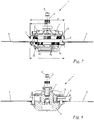
- FIG. 2 an exploded view of a first embodiment of the inventive arrangement is shown.
- the arrangement 1 for fastening a cutting head to an output shaft of a working device comprises an output shaft 5, a hood 7 with a hub 12 and a cutting head 3.
- the output shaft 5 has a two-flat 35.
- the hub 12 of the hood 7 is pushed onto the output shaft 5 and held by means of the double salmon 35 positively against rotation about the axis of rotation 6 on the output shaft 5.
- Other connections between the hub 12 and the output shaft 5 may be appropriate, leading to a rotationally fixed connection between the hood 7 and the output shaft 5.
- the compound may be useful also designed as Reibkraftschlüssige or as cohesive connection. Examples of a corresponding connection are gluing, pressing, feather key connection, connection by means of grub screw.
- the hub 12 has a toothing 34, on which the hood 7 is arranged.
- the hood 7 is connected with its hub 12 by means of the toothing 34 positively in the circumferential direction of the axis of rotation 6 and held against rotation on the output shaft 5.
- the output shaft 5 has at its bottom 31 facing the end ( Fig. 1 ) a thread 36.
- the cutting head 3 is secured by a screw 8 secured against rotation in the cutting head 3 (FIG. Fig. 3 ) screwed onto the thread 36 of the output shaft 5.
- a screw 8 is inserted in the cutting head 3, which is turned together with the cutting head 3 on the thread 36 of the output shaft 5.
- the screw 8 is formed in the embodiment as a screw nut.
- the cutting head 3, the hood 7 with its hub 12 and the output shaft 5 are arranged coaxially to the axis of rotation 6.
- the hood 7 on its outer side 22 first gripping surfaces 13 and ribs 17.
- the cutting head 3 has second gripping surfaces 14 on its outside 26.
- the output shaft 5 can thus be held on the hood 7 via the gripping surfaces 13, while the cutting head 3 is held on the second gripping surfaces 14 and screwed onto the thread 36 of the output shaft 5.
- the cutting head 3 comes with its outside 26 on the hood 7 in the direction of the axis of rotation 6 to the plant.
- the hood 7 is connected via its hub 12 to a support bearing 47 (FIG. Fig. 3 ) supported in the direction of the axis of rotation 6.
- the operator can hold the hood 7 on the first gripping surfaces 13 with one hand and thus block the output shaft 5 in the direction of rotation.
- the operator can grasp the cutting head 3 with its other hand on its second gripping surfaces 14 and screw the cutting head of the thread 36 of the output shaft 5 without turning the output shaft.
- a tool-free assembly and disassembly of the tool head 3 can be done by hand, without the output shaft is directly accessible to the operator.
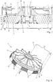
- Fig. 3 is the second embodiment of the inventive arrangement of cutting head 3, hood 7 and the output shaft 5 mounted in the front housing 2 of a erfindungsmä type working device shown.
- the output shaft 5 is rotatably mounted.
- a transmission and / or a drive motor may be arranged, so that the front housing 2 is expediently designed as a transmission housing or as a motor housing.
- the cutting head 3 comprises the screw 8, which is non-rotatably attached to the cutting head 3.
- the screw 8 is secured in the embodiment by means of a toothed disc 48 against axial release of the cutting head 3.
- the screw 8 may also be an inextricably absorbed in the cutting head 3 insert.
- the cutting head 3 is screwed on the screw 36 on the thread 36 of the output shaft 5.
- the cutting head 3 is supported axially via a contact surface 15 of the hood 7. About the contact surface 15, the clamping force between the cutting head 3 and the hood 7 is transmitted substantially.
- the hood 7 is arranged on the hub 12 and is supported against it in the direction of the axis of rotation 6 in a first contact surface 49.
- the hub 12 is in turn tensioned against a arranged on the output shaft 5 support bearing 47 which abuts in the direction of the axis of rotation 6 on a shaft shoulder 51.
- the hub 12 contacts the support bearing 47 in the inner bearing shell in a second contact surface 50. Accordingly, starting from the screw 8 of the cutting head 3 in the direction of the axis of rotation 6 on the hood 7 and the hub 12 to the output shaft 5 ensures a closed power flow.
- the teeth 34 of the hub 12 connects the hub 12 with the hood 7 positively in the circumferential direction of the rotation axis 6.
- the hub 12 is held on the output shaft 5 by the formed on the Abtrieswelle 5 two-line form-fitting in the circumferential direction of the axis of rotation 6.
- the front housing 2 projects beyond its peripheral wall, as in Fig. 3 shown, the hood 7, in particular the ribs 17 of the hood 7, in the direction of the axis of rotation 6.
- the hood 7 protrudes at least partially in the direction of the axis of rotation 6 from the front housing 2 with their first gripping surfaces 13 out.
- the gripping surfaces 13 are thus accessible to the operator.
- limit the front housing 2 and the hood 7 an annular gap 41.
- an air flow 42 is generated during operation of the implement 27, which consists of a trapped by the front housing 2 transmission interior 43 through the annular gap 41 outwardly into the Environment blows. Accordingly, the annular gap 41 forms a gap seal, which prevents the ingress of dirt into the transmission interior 43.
- hood 7 is shown with its hub 12 in a sectional view.
- the hood 7 is cup-shaped in the embodiment.
- the shape of the hood 7 advantageously follows the outer contour of the area covered by it of the cutting head 3.
- the cutting head 3 in the exemplary embodiment has a substantially cylindrical shape.
- the hood 7 comprises a hood bottom 46 extending from the axis of rotation 6 in the radial direction and a hood wall 25 adjoining the hood bottom 46.
- the hood wall 25 extends in the direction of the axis of rotation 6.
- the hood 7 has an inner side 21 facing the cutting head 3 and an inner wall the cutting head 3 facing away from outside 22 ( Fig. 5 ).
- the inner side 21 delimits an inner space 23 of the hood 7.
- the inner side 21 is subdivided into a lower side 10 on the hood bottom 46 and into a circumferential inner side 18 on the hood wall 25.
- the outer side 22 of the hood 7 is subdivided into an upper side 9 on the hood bottom 46 and in a circumferential outer side 11 on the hood wall 25.
- the hood 7 has a relation to the circumferential outer side 11 outer diameter d.
- the outer diameter d starting from the hood base 46, increases slightly in the direction of the axis of rotation 6. Nevertheless, the hood wall 46 in the embodiment in the Essentially cylindrical contour on.
- the cutting head 3 may for example also have a spherical shape.
- the pot-shaped hood 7 advantageously follows there also the outer contour of the covered area of the cutting head 3, so that the hood base 46 and hood wall 25 have a curved course.
- the hood 7 has on the hood wall 46 has a thickness h, which corresponds to the distance between the outer circumferential side 11 and the inner circumferential side 18.
- the thickness h of the hood wall 46 preferably corresponds to less than 5% of the maximum outer diameter d of the hood 7.
- the hood 7 is divided starting from the axis of rotation 6 in the radial direction in an inner region 19 and an adjoining the inner region 19 outer region 20.
- the inner region 19 has a width a, which is measured radially to the rotation axis 6 distance between the outer region 20 and the axis of rotation 6 corresponds.
- the outer region 20 has a width b which corresponds to the distance between the circumferential outer side 11 and the inner region 19 which is measured radially relative to the axis of rotation 6.
- the width a of the inner region corresponds to at least 3 times, in particular at least 5 times, preferably approximately 6 times the width b of the outer region 20.
- the inner region 19 preferably extends from the axis of rotation 6 to the inner peripheral side 18 of the hood wall 25.
- the outer region 20 preferably extends from the circumferential inner side 18 to the peripheral outer side 11 of the hood wall 25.
- the contact surface 15 is formed on the inside 21 of the hood 7.
- the contact surface 15 is formed on the underside 10 of the hood base 46 adjacent to the hub 12 and has a distance e to the axis of rotation 6.
- the contact surface 15 is in particular an annular surface.
- the contact surface 15 extends perpendicular to the axis of rotation 6, but may also be aligned obliquely to the axis of rotation 6 in an alternative embodiment.
- the contact surface 15 is arranged approximately at half the length c of the hood 7.
- the length c of the hood 7 is measured in the direction of the axis of rotation 6.
- a sealing surface 24 trained is trained on the inside 21 of the hood 7 .
- the sealing surface 24 is formed on the underside 10 of the hood base 46 adjacent to the hood wall 25.
- the sealing surface 24 is in particular an annular surface.
- the sealing surface 24 is arranged perpendicular to the axis of rotation 6 in the embodiment. In an alternative embodiment, the sealing surface 24 may also be aligned obliquely or parallel to the axis of rotation 6.
- the sealing surface 24 has a distance f from the axis of rotation 6, which corresponds to at least 4 times, in particular approximately 5 times the distance e between the contact surface 15 and the axis of rotation 6.
- the distance f of the sealing surface 24 corresponds to at least a quarter, in particular at least one third of the outer diameter d of the hood 7.
- the contact surface 15 of the hood 7 serves as a contact surface for the cutting head 3 for clamping the cutting head 3 with the hood 7.
- the cutting head 3 is stretched against the contact surface 15 of the hood 7.
- an elongation 44 is formed on the contact surface 15 of the hood 7, which extends in the direction of the axis of rotation 6.
- the hood 7 is preferably formed by ribbing in the region of elongation. This ensures that the hood 7 in the region of the main power flow between the cutting head 3 and hood 7 has a sufficiently high strength.
- contact the outside 26 of the cutting head 3 with the inside 21 of the hood 7 on the sealing surface 24 of the hood 7 and thus form a seal against dirt. Since the sealing surface 24 is arranged adjacent to the hood wall 25 and thus radially outside the contact surface 15, contamination of the contact surface 15 between the hood 7 and the cutting head 3 is avoided. Both the sealing surface 24 and the contact surface 15 are arranged in the inner region 19.
- the cutting head 3 in the outer region 20 of the hood 7 not.
- the hood 7 and the cutting head 3 have in the outer region 20 of the hood 7 in the radial direction of the axis of rotation 6 extending game 45.
- the game 45 is by a distance between the inner peripheral side 18 of Hood wall 25 and the outside 26 of the cutting head 3 is formed.
- the game extends in the direction of the axis of rotation 6 and extends along the entire hood wall 25, in particular along the first gripping surface 13, to the bottom 10 of the hood base 46. This avoids that in the assembly or disassembly of the cutting head 3 Hood 7 is pressed in the region of the first gripping surface 13 to the cutting head 3 and thus the loosening or fixing of the cutting head 3 is impaired.
- Fig. 6 the hood 7 is shown in a perspective plan view.
- the ribs 17 are formed on the outside 22 of the hood 7, the ribs 17 are formed.
- the ribs 17 extend in the radial direction of the axis of rotation 6 and thereby extend in the direction of the axis of rotation 6.
- the ribs 17 are formed only on the upper side 9 of the hood bottom 46.
- the ribs 17 extend at the upper side 9 through the inner region 19 and protrude into the outer region 20.
- the ribs 17 may be formed only in the inner region 19 of the hood 7.
- the ribs 17 may suitably extend from the top 9 to the peripheral outside 11 of the hood wall 25.
- the ribs 17 may also be suitably formed on the inner side 21 of the hood 7.
- the ribs 17 are in particular arranged in a star shape around the axis of rotation 6.
- the ribs 17 may also be arranged arcuately to the axis of rotation 6.
- the sealing surface 24 is annular around the axis of rotation 6.
- the ribs 17 and the sealing surface 24 are arranged on opposite sides of the hood 7.
- the ribs 17 serve to stiffen the hood 7, so that when gripping the hood 7, a deformation of the hood 7 is avoided.
- the ribs 17 of the hood 7 generate upon rotation of the hood 7 an air flow, so that the hood 7 can be used, for example, as a fan or as an impeller.
- the hood 7 is designed as a fan.
- first gripping surfaces 13 are formed on the hood 7.
- the first gripping surfaces 13 are arranged in the outer region 20 on the outer side 22 of the hood 7.
- the first gripping surfaces 13 are formed on the circumferential outer side 11 of the hood wall 25.
- the first gripping surfaces 13 of the hood 7 in the circumferential direction of the rotation axis 6 on the circumferential outer side 11 of the hood 7 are evenly spaced from each other.
- a non-uniform arrangement of the first gripping surfaces 13 or a single first gripping surface 13 along the entire circumferential outer side 11 may also be expedient.
- the first gripping surface 13 has a corrugated structure, which is formed from individual corrugated elements 39.
- the corrugated elements 39 extend approximately in the direction of the axis of rotation 6. This results in the retention of the hood 7 on the first gripping surfaces 13 a particularly good power transmission in the circumferential direction of the axis of rotation. 6
- second gripping surfaces 14 are formed on the outside 26 of the cutting head 3.
- the second gripping surfaces 14 are uniformly spaced on the outer side 26 of the cutting head 3 in the circumferential direction of the rotation axis 6. It may also be expedient to provide an uneven arrangement of the second gripping surfaces 14 or only a single second gripping surface 14 on the outside 26 of the cutting head 3.
- the second gripping surface 14 of the cutting head 3 has approximately in the direction of the axis of rotation 6 extending corrugation elements 40, which favor a power transmission when holding the cutting head 3 to the second gripping surfaces 14.
- Both the first gripping surface 13 of the hood 7 and the second gripping surface 14 of the cutting head 3 may expediently have different gripping structures. Both the first gripping surfaces 13 of the hood 7 and the second gripping surfaces 14 of the cutting head 3 are freely accessible to the operator.
- the gripping surface 13 has a distance i to the axis of rotation 6, which corresponds to at least 30%, in particular at least 35% of the maximum outer diameter j of the cutting head 3.
- the maximum outer diameter d of the hood 7 corresponds to at most 120%, in particular at most 110% of the maximum outer diameter j of the cutting head 3.
- the first gripping surface 13 has a length g measured in the direction of the axis of rotation 6.
- the cutting head 3 is arranged in the interior 23 of the hood 7, so that the hood 7, the cutting head 3 at least partially enveloped.
- the hood 7 protrudes in the direction of the axis of rotation 6 so far over the cutting head 3 that the hood 7 overlaps the cutting head 3 with the entire length g of the first gripping surface 13.
- two cutting tools 4 are mounted on the cutting head 3. It may be expedient to attach only one cutting tool 4 or several cutting tools 4 to the cutting head 3.
- the cutting tools 4 are formed as cutting blades.
- fastening devices 52 for fastening a cutting thread are provided on the cutting head.
- 4 cutting blades and / or cutting threads can be used in the operation of the cutting head 3 as a cutting tool.
- the cutting heads 3 of the embodiments in the Figures 2 and 3 have in common that they are unscrewed as a unit from the output shaft 5. Although the cutting head 3 may consist of several parts, but these are not moved relative to each other to disassemble the cutting head 3 of the output shaft 5.
- Fig. 9 is a fragmentary view of an embodiment of a working device 27 is shown, in which the arrangement 1 according to the invention is arranged directly on the shaft 29. Accordingly, the cutting head 3 is not connected via a front housing 2, but directly to the shaft 29.
- the output shaft 5 is mounted in the shaft 29 via the support bearing 47.
- the drive shaft not shown, goes directly into the output shaft 5 via.
- the hood 7 and the cutting head 3 are arranged according to the invention.
Landscapes
- Life Sciences & Earth Sciences (AREA)
- Environmental Sciences (AREA)
- Harvester Elements (AREA)
- Sawing (AREA)
Priority Applications (3)
| Application Number | Priority Date | Filing Date | Title |
|---|---|---|---|
| EP18169970.3A EP3560313B1 (fr) | 2018-04-27 | 2018-04-27 | Dispositif de fixation d'une tête de coupe et appareil de travail portatif doté d'un dispositif de fixation d'une tête de coupe |
| US16/396,270 US11006575B2 (en) | 2018-04-27 | 2019-04-26 | Arrangement for fastening a cutting head; portable work appliance having an arrangement for fastening a cutting head |
| CN201910343829.4A CN110402672B (zh) | 2018-04-27 | 2019-04-26 | 用于固定剪切头的组件;带有该组件的便携式工作器械 |
Applications Claiming Priority (1)
| Application Number | Priority Date | Filing Date | Title |
|---|---|---|---|
| EP18169970.3A EP3560313B1 (fr) | 2018-04-27 | 2018-04-27 | Dispositif de fixation d'une tête de coupe et appareil de travail portatif doté d'un dispositif de fixation d'une tête de coupe |
Publications (2)
| Publication Number | Publication Date |
|---|---|
| EP3560313A1 true EP3560313A1 (fr) | 2019-10-30 |
| EP3560313B1 EP3560313B1 (fr) | 2021-11-17 |
Family
ID=62089691
Family Applications (1)
| Application Number | Title | Priority Date | Filing Date |
|---|---|---|---|
| EP18169970.3A Active EP3560313B1 (fr) | 2018-04-27 | 2018-04-27 | Dispositif de fixation d'une tête de coupe et appareil de travail portatif doté d'un dispositif de fixation d'une tête de coupe |
Country Status (3)
| Country | Link |
|---|---|
| US (1) | US11006575B2 (fr) |
| EP (1) | EP3560313B1 (fr) |
| CN (1) | CN110402672B (fr) |
Families Citing this family (4)
| Publication number | Priority date | Publication date | Assignee | Title |
|---|---|---|---|---|
| EP3560313B1 (fr) * | 2018-04-27 | 2021-11-17 | Andreas Stihl AG & Co. KG | Dispositif de fixation d'une tête de coupe et appareil de travail portatif doté d'un dispositif de fixation d'une tête de coupe |
| EP3892083A1 (fr) * | 2020-04-09 | 2021-10-13 | Andreas Stihl AG & Co. KG | Débroussailleuse |
| ES3009690T3 (en) | 2020-04-09 | 2025-03-31 | Stihl Ag & Co Kg Andreas | Handle for a hand-operated tool and free cutter |
| USD1018227S1 (en) * | 2023-04-25 | 2024-03-19 | Junpeng Dai | String trimmer handle |
Citations (3)
| Publication number | Priority date | Publication date | Assignee | Title |
|---|---|---|---|---|
| WO2008053508A2 (fr) * | 2006-11-03 | 2008-05-08 | Fabrizio Arnetoli | Tête de coupe d'herbe de type à ligne |
| EP2747542A1 (fr) * | 2011-08-24 | 2014-07-02 | Proulx Manufacturing, Inc. | Tête de débroussailleuse aérodynamique destinée à être utilisée dans des débroussailleuses rotatives à conduite flexible |
| US20180098492A1 (en) * | 2016-01-22 | 2018-04-12 | Nanjing Chervon Industry Co., Ltd. | Grass trimmer, operating method thereof and control method thereof |
Family Cites Families (17)
| Publication number | Priority date | Publication date | Assignee | Title |
|---|---|---|---|---|
| US4047299A (en) * | 1976-01-30 | 1977-09-13 | Garden Pro, Inc. | Apparatus for trimming vegetation |
| US4236309A (en) * | 1978-02-27 | 1980-12-02 | K & S Industries, Inc. | Flexible line trimmer with line feeding apparatus |
| US4145809A (en) * | 1978-02-27 | 1979-03-27 | Proulx Raymond E | Rotary mower cutting heads with flexible cutting blades |
| US4412382A (en) | 1981-05-04 | 1983-11-01 | The Toro Company | Line feed mechanism for filament cutting |
| DE19736206C1 (de) * | 1997-08-20 | 1999-01-21 | Hans Niedl | Gerät zum Schneiden von Pflanzen |
| US7111403B2 (en) * | 1999-09-21 | 2006-09-26 | Moore Mark R | Head for line trimming apparatus |
| DE202008011648U1 (de) * | 2008-09-02 | 2010-03-11 | Dolmar Gmbh | Kupplungselement |
| DE102010013756A1 (de) * | 2010-03-31 | 2011-10-06 | Andreas Stihl Ag & Co. Kg | Handgeführtes Arbeitsgerät |
| EP2641461B1 (fr) | 2012-03-19 | 2018-12-19 | Robert Bosch GmbH | Tondeuse à fil |
| DE102012007405B4 (de) | 2012-04-16 | 2017-02-09 | Andreas Stihl Ag & Co. Kg | Arbeitsgerät |
| CN105557179B (zh) * | 2014-10-23 | 2018-03-20 | 南京德朔实业有限公司 | 打草机 |
| US10485165B2 (en) * | 2014-11-25 | 2019-11-26 | Chervon (Hk) Limited | Grass trimmer |
| DE102015010579A1 (de) * | 2015-08-12 | 2017-02-16 | Andreas Stihl Ag & Co. Kg | Mähkopf für einen Freischneider |
| CN105940850A (zh) * | 2016-06-14 | 2016-09-21 | 浙江亚特电器有限公司 | 一种多节式打草机 |
| EP3278651A1 (fr) * | 2016-08-04 | 2018-02-07 | Andreas Stihl AG & Co. KG | Dispositif de fixation d'un outil sur un arbre de travail d'un appareil de travail motorise |
| CN106818028B (zh) * | 2017-02-20 | 2018-11-20 | 台州道业科技有限公司 | 一种组合式割草机刀具及其安装和拆卸方法 |
| EP3560313B1 (fr) * | 2018-04-27 | 2021-11-17 | Andreas Stihl AG & Co. KG | Dispositif de fixation d'une tête de coupe et appareil de travail portatif doté d'un dispositif de fixation d'une tête de coupe |
-
2018
- 2018-04-27 EP EP18169970.3A patent/EP3560313B1/fr active Active
-
2019
- 2019-04-26 US US16/396,270 patent/US11006575B2/en active Active
- 2019-04-26 CN CN201910343829.4A patent/CN110402672B/zh active Active
Patent Citations (3)
| Publication number | Priority date | Publication date | Assignee | Title |
|---|---|---|---|---|
| WO2008053508A2 (fr) * | 2006-11-03 | 2008-05-08 | Fabrizio Arnetoli | Tête de coupe d'herbe de type à ligne |
| EP2747542A1 (fr) * | 2011-08-24 | 2014-07-02 | Proulx Manufacturing, Inc. | Tête de débroussailleuse aérodynamique destinée à être utilisée dans des débroussailleuses rotatives à conduite flexible |
| US20180098492A1 (en) * | 2016-01-22 | 2018-04-12 | Nanjing Chervon Industry Co., Ltd. | Grass trimmer, operating method thereof and control method thereof |
Also Published As
| Publication number | Publication date |
|---|---|
| EP3560313B1 (fr) | 2021-11-17 |
| CN110402672A (zh) | 2019-11-05 |
| CN110402672B (zh) | 2022-12-30 |
| US11006575B2 (en) | 2021-05-18 |
| US20190327888A1 (en) | 2019-10-31 |
Similar Documents
| Publication | Publication Date | Title |
|---|---|---|
| EP2997810B1 (fr) | Appareil de travail | |
| EP2798937B1 (fr) | Appareil de travail | |
| EP1491292B1 (fr) | Disque de meulage | |
| DE10034437B4 (de) | Handgeführtes Arbeitsgerät | |
| DE102007020542B4 (de) | Werkzeug mit Drehmomentverstärkung | |
| EP0253181B1 (fr) | Mécanisme de fixation d'outils en forme de disque sur une broche de machine-outil électrique portative | |
| EP0235598B1 (fr) | Meuleuse entraînée par un moteur électrique | |
| EP3560313B1 (fr) | Dispositif de fixation d'une tête de coupe et appareil de travail portatif doté d'un dispositif de fixation d'une tête de coupe | |
| DE60124669T2 (de) | Kupplungsanordnung für rotierendes scheibenförmiges Werkzeug | |
| DE69909025T2 (de) | Tragbarer , motorbetriebener Buschschneider | |
| DE102007041840A1 (de) | Handwerkzeugmaschine mit Schutzhaube, insbesondere Winkelschleifer | |
| WO1988005386A1 (fr) | Dispositif de serrage pour le blocage axial d'un outil, notamment d'une meule | |
| DE102009000402A1 (de) | Sicheres drehmomentverstärkendes Werkzeug | |
| DE202008001759U1 (de) | Oszillierend antreibbare Werkzeugmaschine | |
| DE2357176A1 (de) | Vorrichtung zum schneiden von stroh und dergl | |
| AT390162B (de) | Maehbalken mit um annaehernd senkrechte achsen umlaufenden scheiben | |
| DE102010018919A1 (de) | Vorsatzgerät für eine Hand-Werkzeugmaschine und damit ausgestattete Hand-Werkzeugmaschine | |
| EP3925427A1 (fr) | Tête de coupe pour une débroussailleuse | |
| DE102024115954B3 (de) | Werkzeugantriebseinheit für ein Schneidmesser eines handgehaltenen Arbeitsgeräts, sowie handgehaltenes Arbeitsgerät mit der Werkzeugantriebseinheit | |
| EP0368051B1 (fr) | Ouvre-boîte manuel motorisé | |
| DE4239559C2 (de) | Handwerkzeugmaschine mit einer Blockiereinrichtung zum Blockieren der Werkzeugspindel beim Werkzeugwechsel | |
| DE212016000231U1 (de) | Schleifmaschine | |
| DE10318324A1 (de) | Kantenschneider | |
| DE2121182A1 (de) | Riemenscheibenkonstruktion | |
| DE3603461C2 (fr) |
Legal Events
| Date | Code | Title | Description |
|---|---|---|---|
| PUAI | Public reference made under article 153(3) epc to a published international application that has entered the european phase |
Free format text: ORIGINAL CODE: 0009012 |
|
| STAA | Information on the status of an ep patent application or granted ep patent |
Free format text: STATUS: THE APPLICATION HAS BEEN PUBLISHED |
|
| AK | Designated contracting states |
Kind code of ref document: A1 Designated state(s): AL AT BE BG CH CY CZ DE DK EE ES FI FR GB GR HR HU IE IS IT LI LT LU LV MC MK MT NL NO PL PT RO RS SE SI SK SM TR |
|
| AX | Request for extension of the european patent |
Extension state: BA ME |
|
| STAA | Information on the status of an ep patent application or granted ep patent |
Free format text: STATUS: REQUEST FOR EXAMINATION WAS MADE |
|
| 17P | Request for examination filed |
Effective date: 20200220 |
|
| RBV | Designated contracting states (corrected) |
Designated state(s): AL AT BE BG CH CY CZ DE DK EE ES FI FR GB GR HR HU IE IS IT LI LT LU LV MC MK MT NL NO PL PT RO RS SE SI SK SM TR |
|
| STAA | Information on the status of an ep patent application or granted ep patent |
Free format text: STATUS: EXAMINATION IS IN PROGRESS |
|
| 17Q | First examination report despatched |
Effective date: 20200917 |
|
| GRAP | Despatch of communication of intention to grant a patent |
Free format text: ORIGINAL CODE: EPIDOSNIGR1 |
|
| STAA | Information on the status of an ep patent application or granted ep patent |
Free format text: STATUS: GRANT OF PATENT IS INTENDED |
|
| INTG | Intention to grant announced |
Effective date: 20210609 |
|
| GRAS | Grant fee paid |
Free format text: ORIGINAL CODE: EPIDOSNIGR3 |
|
| GRAA | (expected) grant |
Free format text: ORIGINAL CODE: 0009210 |
|
| STAA | Information on the status of an ep patent application or granted ep patent |
Free format text: STATUS: THE PATENT HAS BEEN GRANTED |
|
| AK | Designated contracting states |
Kind code of ref document: B1 Designated state(s): AL AT BE BG CH CY CZ DE DK EE ES FI FR GB GR HR HU IE IS IT LI LT LU LV MC MK MT NL NO PL PT RO RS SE SI SK SM TR |
|
| REG | Reference to a national code |
Ref country code: GB Ref legal event code: FG4D Free format text: NOT ENGLISH |
|
| REG | Reference to a national code |
Ref country code: DE Ref legal event code: R096 Ref document number: 502018007855 Country of ref document: DE |
|
| REG | Reference to a national code |
Ref country code: IE Ref legal event code: FG4D Free format text: LANGUAGE OF EP DOCUMENT: GERMAN |
|
| REG | Reference to a national code |
Ref country code: AT Ref legal event code: REF Ref document number: 1447291 Country of ref document: AT Kind code of ref document: T Effective date: 20211215 |
|
| REG | Reference to a national code |
Ref country code: LT Ref legal event code: MG9D |
|
| REG | Reference to a national code |
Ref country code: NL Ref legal event code: MP Effective date: 20211117 |
|
| PG25 | Lapsed in a contracting state [announced via postgrant information from national office to epo] |
Ref country code: RS Free format text: LAPSE BECAUSE OF FAILURE TO SUBMIT A TRANSLATION OF THE DESCRIPTION OR TO PAY THE FEE WITHIN THE PRESCRIBED TIME-LIMIT Effective date: 20211117 Ref country code: LT Free format text: LAPSE BECAUSE OF FAILURE TO SUBMIT A TRANSLATION OF THE DESCRIPTION OR TO PAY THE FEE WITHIN THE PRESCRIBED TIME-LIMIT Effective date: 20211117 Ref country code: FI Free format text: LAPSE BECAUSE OF FAILURE TO SUBMIT A TRANSLATION OF THE DESCRIPTION OR TO PAY THE FEE WITHIN THE PRESCRIBED TIME-LIMIT Effective date: 20211117 Ref country code: BG Free format text: LAPSE BECAUSE OF FAILURE TO SUBMIT A TRANSLATION OF THE DESCRIPTION OR TO PAY THE FEE WITHIN THE PRESCRIBED TIME-LIMIT Effective date: 20220217 |
|
| PG25 | Lapsed in a contracting state [announced via postgrant information from national office to epo] |
Ref country code: IS Free format text: LAPSE BECAUSE OF FAILURE TO SUBMIT A TRANSLATION OF THE DESCRIPTION OR TO PAY THE FEE WITHIN THE PRESCRIBED TIME-LIMIT Effective date: 20220317 Ref country code: SE Free format text: LAPSE BECAUSE OF FAILURE TO SUBMIT A TRANSLATION OF THE DESCRIPTION OR TO PAY THE FEE WITHIN THE PRESCRIBED TIME-LIMIT Effective date: 20211117 Ref country code: PT Free format text: LAPSE BECAUSE OF FAILURE TO SUBMIT A TRANSLATION OF THE DESCRIPTION OR TO PAY THE FEE WITHIN THE PRESCRIBED TIME-LIMIT Effective date: 20220317 Ref country code: PL Free format text: LAPSE BECAUSE OF FAILURE TO SUBMIT A TRANSLATION OF THE DESCRIPTION OR TO PAY THE FEE WITHIN THE PRESCRIBED TIME-LIMIT Effective date: 20211117 Ref country code: NO Free format text: LAPSE BECAUSE OF FAILURE TO SUBMIT A TRANSLATION OF THE DESCRIPTION OR TO PAY THE FEE WITHIN THE PRESCRIBED TIME-LIMIT Effective date: 20220217 Ref country code: NL Free format text: LAPSE BECAUSE OF FAILURE TO SUBMIT A TRANSLATION OF THE DESCRIPTION OR TO PAY THE FEE WITHIN THE PRESCRIBED TIME-LIMIT Effective date: 20211117 Ref country code: LV Free format text: LAPSE BECAUSE OF FAILURE TO SUBMIT A TRANSLATION OF THE DESCRIPTION OR TO PAY THE FEE WITHIN THE PRESCRIBED TIME-LIMIT Effective date: 20211117 Ref country code: HR Free format text: LAPSE BECAUSE OF FAILURE TO SUBMIT A TRANSLATION OF THE DESCRIPTION OR TO PAY THE FEE WITHIN THE PRESCRIBED TIME-LIMIT Effective date: 20211117 Ref country code: GR Free format text: LAPSE BECAUSE OF FAILURE TO SUBMIT A TRANSLATION OF THE DESCRIPTION OR TO PAY THE FEE WITHIN THE PRESCRIBED TIME-LIMIT Effective date: 20220218 Ref country code: ES Free format text: LAPSE BECAUSE OF FAILURE TO SUBMIT A TRANSLATION OF THE DESCRIPTION OR TO PAY THE FEE WITHIN THE PRESCRIBED TIME-LIMIT Effective date: 20211117 |
|
| PG25 | Lapsed in a contracting state [announced via postgrant information from national office to epo] |
Ref country code: SM Free format text: LAPSE BECAUSE OF FAILURE TO SUBMIT A TRANSLATION OF THE DESCRIPTION OR TO PAY THE FEE WITHIN THE PRESCRIBED TIME-LIMIT Effective date: 20211117 Ref country code: SK Free format text: LAPSE BECAUSE OF FAILURE TO SUBMIT A TRANSLATION OF THE DESCRIPTION OR TO PAY THE FEE WITHIN THE PRESCRIBED TIME-LIMIT Effective date: 20211117 Ref country code: RO Free format text: LAPSE BECAUSE OF FAILURE TO SUBMIT A TRANSLATION OF THE DESCRIPTION OR TO PAY THE FEE WITHIN THE PRESCRIBED TIME-LIMIT Effective date: 20211117 Ref country code: EE Free format text: LAPSE BECAUSE OF FAILURE TO SUBMIT A TRANSLATION OF THE DESCRIPTION OR TO PAY THE FEE WITHIN THE PRESCRIBED TIME-LIMIT Effective date: 20211117 Ref country code: DK Free format text: LAPSE BECAUSE OF FAILURE TO SUBMIT A TRANSLATION OF THE DESCRIPTION OR TO PAY THE FEE WITHIN THE PRESCRIBED TIME-LIMIT Effective date: 20211117 Ref country code: CZ Free format text: LAPSE BECAUSE OF FAILURE TO SUBMIT A TRANSLATION OF THE DESCRIPTION OR TO PAY THE FEE WITHIN THE PRESCRIBED TIME-LIMIT Effective date: 20211117 |
|
| REG | Reference to a national code |
Ref country code: DE Ref legal event code: R097 Ref document number: 502018007855 Country of ref document: DE |
|
| PLBE | No opposition filed within time limit |
Free format text: ORIGINAL CODE: 0009261 |
|
| STAA | Information on the status of an ep patent application or granted ep patent |
Free format text: STATUS: NO OPPOSITION FILED WITHIN TIME LIMIT |
|
| 26N | No opposition filed |
Effective date: 20220818 |
|
| PG25 | Lapsed in a contracting state [announced via postgrant information from national office to epo] |
Ref country code: AL Free format text: LAPSE BECAUSE OF FAILURE TO SUBMIT A TRANSLATION OF THE DESCRIPTION OR TO PAY THE FEE WITHIN THE PRESCRIBED TIME-LIMIT Effective date: 20211117 |
|
| PG25 | Lapsed in a contracting state [announced via postgrant information from national office to epo] |
Ref country code: SI Free format text: LAPSE BECAUSE OF FAILURE TO SUBMIT A TRANSLATION OF THE DESCRIPTION OR TO PAY THE FEE WITHIN THE PRESCRIBED TIME-LIMIT Effective date: 20211117 |
|
| REG | Reference to a national code |
Ref country code: CH Ref legal event code: PL |
|
| REG | Reference to a national code |
Ref country code: BE Ref legal event code: MM Effective date: 20220430 |
|
| PG25 | Lapsed in a contracting state [announced via postgrant information from national office to epo] |
Ref country code: MC Free format text: LAPSE BECAUSE OF FAILURE TO SUBMIT A TRANSLATION OF THE DESCRIPTION OR TO PAY THE FEE WITHIN THE PRESCRIBED TIME-LIMIT Effective date: 20211117 Ref country code: LU Free format text: LAPSE BECAUSE OF NON-PAYMENT OF DUE FEES Effective date: 20220427 Ref country code: LI Free format text: LAPSE BECAUSE OF NON-PAYMENT OF DUE FEES Effective date: 20220430 Ref country code: CH Free format text: LAPSE BECAUSE OF NON-PAYMENT OF DUE FEES Effective date: 20220430 |
|
| PG25 | Lapsed in a contracting state [announced via postgrant information from national office to epo] |
Ref country code: BE Free format text: LAPSE BECAUSE OF NON-PAYMENT OF DUE FEES Effective date: 20220430 |
|
| PG25 | Lapsed in a contracting state [announced via postgrant information from national office to epo] |
Ref country code: IE Free format text: LAPSE BECAUSE OF NON-PAYMENT OF DUE FEES Effective date: 20220427 |
|
| PG25 | Lapsed in a contracting state [announced via postgrant information from national office to epo] |
Ref country code: IT Free format text: LAPSE BECAUSE OF FAILURE TO SUBMIT A TRANSLATION OF THE DESCRIPTION OR TO PAY THE FEE WITHIN THE PRESCRIBED TIME-LIMIT Effective date: 20211117 |
|
| PG25 | Lapsed in a contracting state [announced via postgrant information from national office to epo] |
Ref country code: HU Free format text: LAPSE BECAUSE OF FAILURE TO SUBMIT A TRANSLATION OF THE DESCRIPTION OR TO PAY THE FEE WITHIN THE PRESCRIBED TIME-LIMIT; INVALID AB INITIO Effective date: 20180427 |
|
| PG25 | Lapsed in a contracting state [announced via postgrant information from national office to epo] |
Ref country code: MK Free format text: LAPSE BECAUSE OF FAILURE TO SUBMIT A TRANSLATION OF THE DESCRIPTION OR TO PAY THE FEE WITHIN THE PRESCRIBED TIME-LIMIT Effective date: 20211117 Ref country code: CY Free format text: LAPSE BECAUSE OF FAILURE TO SUBMIT A TRANSLATION OF THE DESCRIPTION OR TO PAY THE FEE WITHIN THE PRESCRIBED TIME-LIMIT Effective date: 20211117 |
|
| REG | Reference to a national code |
Ref country code: AT Ref legal event code: MM01 Ref document number: 1447291 Country of ref document: AT Kind code of ref document: T Effective date: 20230427 |
|
| PG25 | Lapsed in a contracting state [announced via postgrant information from national office to epo] |
Ref country code: TR Free format text: LAPSE BECAUSE OF FAILURE TO SUBMIT A TRANSLATION OF THE DESCRIPTION OR TO PAY THE FEE WITHIN THE PRESCRIBED TIME-LIMIT Effective date: 20211117 |
|
| PG25 | Lapsed in a contracting state [announced via postgrant information from national office to epo] |
Ref country code: AT Free format text: LAPSE BECAUSE OF NON-PAYMENT OF DUE FEES Effective date: 20230427 |
|
| PG25 | Lapsed in a contracting state [announced via postgrant information from national office to epo] |
Ref country code: AT Free format text: LAPSE BECAUSE OF NON-PAYMENT OF DUE FEES Effective date: 20230427 |
|
| PG25 | Lapsed in a contracting state [announced via postgrant information from national office to epo] |
Ref country code: MT Free format text: LAPSE BECAUSE OF FAILURE TO SUBMIT A TRANSLATION OF THE DESCRIPTION OR TO PAY THE FEE WITHIN THE PRESCRIBED TIME-LIMIT Effective date: 20211117 |
|
| PGFP | Annual fee paid to national office [announced via postgrant information from national office to epo] |
Ref country code: DE Payment date: 20250428 Year of fee payment: 8 |
|
| PGFP | Annual fee paid to national office [announced via postgrant information from national office to epo] |
Ref country code: GB Payment date: 20250422 Year of fee payment: 8 |
|
| PGFP | Annual fee paid to national office [announced via postgrant information from national office to epo] |
Ref country code: FR Payment date: 20250424 Year of fee payment: 8 |
|
| PGFP | Annual fee paid to national office [announced via postgrant information from national office to epo] |
Ref country code: AT Payment date: 20260410 Year of fee payment: 5 |