EP3560318B1 - Machine de fenaison à rotors pourvus d'outils sécurisés - Google Patents
Machine de fenaison à rotors pourvus d'outils sécurisés Download PDFInfo
- Publication number
- EP3560318B1 EP3560318B1 EP19169744.0A EP19169744A EP3560318B1 EP 3560318 B1 EP3560318 B1 EP 3560318B1 EP 19169744 A EP19169744 A EP 19169744A EP 3560318 B1 EP3560318 B1 EP 3560318B1
- Authority
- EP
- European Patent Office
- Prior art keywords
- nut
- bolt
- support arm
- component
- machine according
- Prior art date
- Legal status (The legal status is an assumption and is not a legal conclusion. Google has not performed a legal analysis and makes no representation as to the accuracy of the status listed.)
- Active
Links
Images

Classifications
-
- A—HUMAN NECESSITIES
- A01—AGRICULTURE; FORESTRY; ANIMAL HUSBANDRY; HUNTING; TRAPPING; FISHING
- A01D—HARVESTING; MOWING
- A01D80/00—Parts or details of, or accessories for, haymakers
- A01D80/02—Tines; Attachment of tines
-
- A—HUMAN NECESSITIES
- A01—AGRICULTURE; FORESTRY; ANIMAL HUSBANDRY; HUNTING; TRAPPING; FISHING
- A01D—HARVESTING; MOWING
- A01D34/00—Mowers; Mowing apparatus of harvesters
-
- A—HUMAN NECESSITIES
- A01—AGRICULTURE; FORESTRY; ANIMAL HUSBANDRY; HUNTING; TRAPPING; FISHING
- A01D—HARVESTING; MOWING
- A01D75/00—Accessories for harvesters or mowers
- A01D75/18—Safety devices for parts of the machines
-
- A—HUMAN NECESSITIES
- A01—AGRICULTURE; FORESTRY; ANIMAL HUSBANDRY; HUNTING; TRAPPING; FISHING
- A01D—HARVESTING; MOWING
- A01D78/00—Haymakers with tines moving with respect to the machine
- A01D78/005—Turners; Tedders
- A01D78/006—Rotating turners
Definitions
- the invention relates more particularly to a haymaking machine comprising at least one rotor comprising at least one radially extending rotary support arm, with an inner end connected to the hub of the rotor and an opposite outer end carrying at least one working tool having strands. connected by an intermediate portion having, on the one hand, turns and, on the other hand, at least one bent section for fixing to the support arm, this arm extending internally through at least some of the turns and a retention part turns separated from the support arm being attached to the latter.
- the rotors are typically mounted aligned on a rolling frame.
- the two strands, the turns and the elbow fixing part of each working tool are generally formed from a single segment of steel wire shaped to constitute the tool.
- the strands can be subjected to significant forces, due to the advance of the machine for example or when a work tool encounters a large obstacle such as a bollard or a large stone partially. buried, and the turns close to the outer strand (which is the most stressed) then undergo significant deformations which can lead to rupture at their level. In this case, the turns located towards the outside beyond the breaking point and the corresponding outer strand detach from the arm. Such a detached strand is dangerous if it is thrown into the air. In addition, it can get lost in the forage and cause considerable damage if it were to pass through a baler or forage harvester being used for harvesting.
- the part providing the aforementioned double function is of complex construction and especially its fixing by means of a bolt, which simultaneously secures the working tool with the support arm, is tedious and time consuming for the fitter. .
- Another known solution provides retention at the level of the strands and not of the turns, by joining them together, which limits the flexibility of the tool.
- the object of the invention is to provide a simple and inexpensive constructive solution, allowing the retention on the support arm of the detached part of a broken working tool, which can be implemented with a solid or hollow support arm, of which the number of parts is reduced and the assembly is facilitated.
- this solution should, if possible, be easily combined with the production or attachment of a protective cover.
- the invention relates to a haymaking machine comprising at least one rotor comprising at least one radially extending rotary support arm, with an inner end connected to the hub of the rotor and an opposite outer end carrying at least one cutting tool.
- job having strands connected by an intermediate portion having, on the one hand, turns and, on the other hand, at least one bent section for fixing to the support arm, this arm extending internally through at least some of the turns and a part for retaining turns separated from the support arm being attached to the latter, machine characterized in that said retention part incorporates at least part of the means or means for fixing the work tool concerned on the support arm.
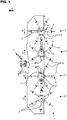
- a haymaking machine 1 of the tedder or rotary plant spreader type typically comprises a frame 1 secured to a coupling support 1 ", preferably of the three-point type, for attachment to a tractor or the like.
- the frame 1 ' can be fitted with wheels and / or be carried by the tractor in the transport position of the machine 1.
- the frame 1 ' carries a number of rotors 2 each consisting of several radial arms 3 arranged around a hub 2' which defines, for the rotor 2 concerned, an axis of rotation with vertical orientation or slightly inclined, preferably towards the center. 'forward (direction of advance in use).
- These rotors 2 present in an even number and being able to present opposite directions of rotation two by two (see direction of rotation B and C on the figure 1 ) to move the plants, preferably backwards in order to turn them over and distribute them on the ground, are rotated by the power take-off of the tractor or the like.
- the rotors 2 can be driven so as to constitute windrows.
- each rotor 2 is fitted with one or more support rollers on the ground (not visible on the figure 1 ), preferably crazy climb (s).
- the tools 5 with the branches 6 rake the ground to lift and move mown and loose plants, such as grass or straw, in order to turn them over. , and to disperse them or to assemble them in swaths (depending on the setting of the machine 1).
- said retention part 9 incorporates at least part of the fixing means 10 of the working tool 5 concerned on the support arm 3.
- the invention makes it possible to reduce the number of separate parts to be implemented for the assembly of the working tool 5 with the support arm 3, allows simultaneous securing of the retention part 9 and of the working tool 5 with the support arm 3 and above all makes the operation of mounting and assembling these elements 5 and 9 easier and less tedious.
- each fixing means 10 is, for example, made up of two components cooperating with each other to provide the connection or joining function, it can be provided that one of these two components, or at least the functional part connection or securing of one of these two components, either integrated or incorporated in the retention part 9.
- the or each fixing means 10 consists of a bolt and said retention part 9 incorporates a thread of one of the two components 11 and 11 'of said or each bolt 10, namely the nut 11 or the screw 11 '.
- each bolt 10 also comprises a support washer 11 "and a single bolt 10 is provided for each tool 5.
- the screw 11 'or the nut 11 of the or each bolt 10 integrated in the retention part 9 is a separate element held and retained in a cutout 12 of said retention part 9.
- the screw 11 'or the nut 11 is locked in rotation in, preferably by, the retention part 9, and preferably around the axis of the bolt 10.
- the screw 11 'or the nut 11 is locked in rotation around the axis of the bolt 10 in the cutout 12, preferably by the cutout 12 itself.
- the retention part 9 thus serving as a holding part for one of the two components.
- a single bolt 10 is provided for fixing each working tool 5.
- the retention part 9 is attached externally to one face of an outer end portion 4 "of the support arm 3, preferably with a solid structure.
- the part 9 may comprise two walls 13, 13 ', one of which 13 has a cutout 12 forming an indentation for maintaining and locking in rotation the nut 11 or the head 14 of the screw 11 'and the other 13' of which has an orifice 15 for passage of the rod 14 'of the screw 11', the nut 11 or the screw head 14 being trapped between these two walls 13 and 13 ', preferably with a slight clearance.
- the nut 11 or the screw head 14 may include a flange or a radial shoulder 16, the diameter of which is at least slightly greater than both the cutout. 12 and to the orifice 15 for passage of the rod 14 'of the screw 11'.
- the component 11 or 11 ' is thus incorporated in a captive manner in the retention part 9 by mechanical assembly and is held relatively fixed in the latter.
- the component 11, 11 'of the or each bolt 10, which is integrated in the retention part 9, is rigidly secured (for example by welding) or produced in one piece with said retention part 9.
- the retention part 9 can thus constitute the screw 11 'or the nut 11 of the bolt 10 and, according to this embodiment, the retention part 9 incorporates one of the constituent and mutually cooperating components 11 or 11' of the means ( 10 fixing concerned (s).
- the retention part 9 can incorporate one of the components 11 or 11 'by making them in one piece.
- the part in one piece can then for example be produced by tapping, preferably preceded by flow drilling.
- one of the components 11 or 11 ' can be assembled in a rigid and non-removable manner with the part 9, for example by gluing or welding.
- the production of the retention part 9 makes it possible to immediately incorporate the net.
- the cavity or the recess 20 which is present in one of the parts 4 ", 11, 11 'or 21 in direct contact with said bent section 8', and ensures its connection with rigid retention by pinching, reports 'at least one surface portion conforming to the rounded outer shape (sectional view) of said bent section 8 and thereby makes it possible to provide an increased contact area by cooperation of shape, thus ensuring better fixing and better holding.
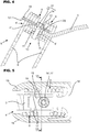
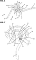
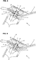
- the figures 3 to 9 illustrate different constructive variants for carrying out the wedging fixing with clamping.
- the cavity or the recess 20 can be formed (for example by machining) directly in the arm 3 (at the level of the portion 4 "), as shown in the figures. figures 3 , 4 , 6 and 7 .
- this cavity or this recess 20 can also be formed in the nut 11 or in the screw head 14 of the bolt 10.
- the retention part 9 may comprise two walls 13 and 13 'extending on either side of the outer end portion 4 "of the support arm 3, by sandwiching this portion between them, preferably with a pinch elastic even in the absence of tightening, these walls 13 and 13 'cooperating with the two components 11 and 11' of the fixing means 10 and with the intermediate adapter piece 21 to secure the retention piece 9 and the bent section 8 'with the end portion 4 ".
- one of the walls 13 and 13 'of the retention part 9 carries or integrates the component 11 forming the nut of the fixing means 10 and that the other wall, located on the opposite side of the outer end portion 4 ", carries or integrates the intermediate adapter piece 21.
- the nut 11 can be welded to the wall 13 considered or be formed as an integral part of this wall 13 (the screw 11 'passes through the end portion 4 ", the two walls 13 and 13' which surround it and the adaptation part 21 at the level of through and coinciding orifices).
- the adaptation part 21 may consist of a separate part attached to the wall 13 'and secured to the latter for example by assembly with mechanical engagement locked by welding, gluing or crimping ( figure 8 ).
- the adaptation piece 21 can also, as a variant, be made in one piece with the retention piece 9 and constitute part of the wall 13 '( figure 9 ), the cavity or the recess 20 then being formed in this part 9.
- an advantage of this third embodiment is that the arm 3 is wedged by the retention part 9.
- the retention part 9 is advantageously retained by wedging on the arm 3 (even when the rod 14 'of the screw 11 'is not engaged in the orifices 15 or of the arm 3) which also facilitates assembly.
- it is simpler and less expensive to carry out machining on a piece of small caliber such as the retention piece 9, respectively the adapter piece 21, than in a bulky piece such as the arm 3.
- the nut 11 can be formed in one piece or attached with rigid fixing at the level of the wall 13 of the part 9.
- said retention part 9 may comprise a guide means 17 preventing its rotation relative to the support arm 3 around the axis of the bolt 10, said guide means 17 advantageously comprising at least one tab or one wing (see figures 2 and 5 for example).
- This guide means 17 can also facilitate alignment during assembly between part 9 and arm 3.
- One or more pair (s) of opposing legs 17 can effectively ensure the above-mentioned alignment and locking between the part 9 and the support arm 3.
- the retention part 9 is constituted by a first part 18 for joining with the support arm 3, extending into the turns 8 and integrating a part 11, 11 'of the means 10 of fixing of the working tool 5 and by a second retention part 18 ', extending beyond the last outer turn and having a transverse dimension greater than the inner diameter of the turns 8.
- the retention part 9 has a generally flat and planar shape, where appropriate double-walled, T-shaped or double hook.
- the retention part can also form a protective cover 19 and an external covering, at least partially, of the turns 8 of the working tool 5.
- the cover 19 is then formed by an extension in one piece of the second part 18 'of the retention part 9, said cover 19 possibly being connected at at least one second point to the support arm 3.
- the constitution of the retention part 9 can then be similar to that described and shown in the document EP 1 929 857 above.
- such a cover 19 can also be a separate part fixed to the support arm 3 concerned, possibly at least partially by means of the retention part 9, on which it can for example be fitted.
- the cover 19 can, for its part, be a plastic part when it is attached separately.
Landscapes
- Life Sciences & Earth Sciences (AREA)
- Environmental Sciences (AREA)
- Mutual Connection Of Rods And Tubes (AREA)
- Connection Of Plates (AREA)
- Harvester Elements (AREA)
Priority Applications (2)
| Application Number | Priority Date | Filing Date | Title |
|---|---|---|---|
| PL19169744T PL3560318T3 (pl) | 2018-04-26 | 2019-04-17 | Maszyna do sianokosów z wirnikami wyposażonymi w zabezpieczone narzędzia |
| SI201930068T SI3560318T1 (sl) | 2018-04-26 | 2019-04-17 | Stroj za spravilo sena z rotorji, opremljenimi s pritrjenimi orodji |
Applications Claiming Priority (1)
| Application Number | Priority Date | Filing Date | Title |
|---|---|---|---|
| FR1853653A FR3080517B1 (fr) | 2018-04-26 | 2018-04-26 | Machine de fenaison a rotors pourvus d'outils securises |
Publications (2)
| Publication Number | Publication Date |
|---|---|
| EP3560318A1 EP3560318A1 (fr) | 2019-10-30 |
| EP3560318B1 true EP3560318B1 (fr) | 2021-03-10 |
Family
ID=62684944
Family Applications (1)
| Application Number | Title | Priority Date | Filing Date |
|---|---|---|---|
| EP19169744.0A Active EP3560318B1 (fr) | 2018-04-26 | 2019-04-17 | Machine de fenaison à rotors pourvus d'outils sécurisés |
Country Status (8)
| Country | Link |
|---|---|
| US (1) | US20190327898A1 (pl) |
| EP (1) | EP3560318B1 (pl) |
| CN (1) | CN110402691A (pl) |
| CA (1) | CA3039993A1 (pl) |
| DK (1) | DK3560318T3 (pl) |
| FR (1) | FR3080517B1 (pl) |
| PL (1) | PL3560318T3 (pl) |
| SI (1) | SI3560318T1 (pl) |
Cited By (1)
| Publication number | Priority date | Publication date | Assignee | Title |
|---|---|---|---|---|
| PL440739A1 (pl) * | 2022-03-22 | 2023-09-25 | Samasz Spółka Z Ograniczoną Odpowiedzialnością | Urządzenie do stabilizacji grabionego wałka w maszynach do zbioru pasz objętościowych i słomy |
Family Cites Families (7)
| Publication number | Priority date | Publication date | Assignee | Title |
|---|---|---|---|---|
| US2608046A (en) * | 1950-03-28 | 1952-08-26 | New Holland Machine Division O | Side rake tooth mounting |
| NL296784A (pl) | 1963-08-16 | |||
| DE8806149U1 (de) * | 1988-05-09 | 1989-09-14 | Alois Pöttinger Landmaschinen-Gesellschaft mbH, 8900 Augsburg | Zinkenbefestigung für Heuwerbungsmaschinen |
| DE20117668U1 (de) * | 2001-10-29 | 2002-02-28 | Gebr. Pöttinger GmbH, 86899 Landsberg | Befestigungsvorrichtung für Federzinken von Heuwerbungsmaschinen |
| FR2908957B1 (fr) * | 2006-11-27 | 2011-03-18 | Kuhn Sa | Machine de fenaison avec des moyens de protection |
| DE202013005176U1 (de) * | 2013-06-06 | 2014-09-08 | Alois Pöttinger Maschinenfabrik Ges.m.b.H. | Heuwerbungsmaschine |
| DE102015010891B4 (de) * | 2015-08-19 | 2017-08-17 | Maschinenfabrik Bernard Krone Gmbh | Heuwerbungsmaschine mit verbessertem Kreiselarm |
-
2018
- 2018-04-26 FR FR1853653A patent/FR3080517B1/fr not_active Expired - Fee Related
-
2019
- 2019-04-10 CA CA3039993A patent/CA3039993A1/fr active Pending
- 2019-04-17 PL PL19169744T patent/PL3560318T3/pl unknown
- 2019-04-17 DK DK19169744.0T patent/DK3560318T3/da active
- 2019-04-17 SI SI201930068T patent/SI3560318T1/sl unknown
- 2019-04-17 EP EP19169744.0A patent/EP3560318B1/fr active Active
- 2019-04-25 US US16/394,110 patent/US20190327898A1/en not_active Abandoned
- 2019-04-26 CN CN201910342654.5A patent/CN110402691A/zh active Pending
Non-Patent Citations (1)
| Title |
|---|
| None * |
Cited By (2)
| Publication number | Priority date | Publication date | Assignee | Title |
|---|---|---|---|---|
| PL440739A1 (pl) * | 2022-03-22 | 2023-09-25 | Samasz Spółka Z Ograniczoną Odpowiedzialnością | Urządzenie do stabilizacji grabionego wałka w maszynach do zbioru pasz objętościowych i słomy |
| PL248757B1 (pl) * | 2022-03-22 | 2026-01-26 | Samasz Spolka Z Ograniczona Odpowiedzialnoscia | Urządzenie do stabilizacji grabionego wałka w maszynach do zbioru pasz objętościowych i słomy |
Also Published As
| Publication number | Publication date |
|---|---|
| EP3560318A1 (fr) | 2019-10-30 |
| FR3080517A1 (fr) | 2019-11-01 |
| SI3560318T1 (sl) | 2021-08-31 |
| CA3039993A1 (fr) | 2019-10-26 |
| DK3560318T3 (da) | 2021-06-14 |
| FR3080517B1 (fr) | 2020-09-25 |
| US20190327898A1 (en) | 2019-10-31 |
| PL3560318T3 (pl) | 2021-10-04 |
| CN110402691A (zh) | 2019-11-05 |
Similar Documents
| Publication | Publication Date | Title |
|---|---|---|
| EP2380424B1 (fr) | Tête de coupe rotative utilisant des éléments de coupe flexibles filiformes, et appareils de coupe munis d'une telle tête de coupe. | |
| EP1163832B1 (fr) | Machine de coupe | |
| EP0239515A1 (fr) | Faucheuse rotative | |
| EP0403409B1 (fr) | Machine agricole pour l'andainage comportant des bras porte-outils repliables | |
| CA2808507C (fr) | Rotor d'une machine de fenaison muni de bras en deux parties reliees par un dispositif de liaison perfectionne | |
| EP0517632B1 (fr) | Machine agricole, notamment une andaineuse de végétaux | |
| EP2978987B1 (fr) | Dispositif limiteur de couple et machine agricole l'utilisant | |
| EP3560318A1 (fr) | Machine de fenaison à rotors pourvus d'outils sécurisés | |
| EP1929857B1 (fr) | Machine de fenaison avec des moyens de protection | |
| EP0514302B1 (fr) | Andaineuse de végétaux perfectionnée | |
| FR2685162A1 (fr) | Dispositif cueilleur repliable pour la recolte du mauis ou plantes similaires. | |
| EP3769605B1 (fr) | Dispositif de ramassage pour machine de traitement de végétaux coupés et machine correspondante | |
| FR3080738A1 (fr) | Machine agricole pour la recolte de vegetaux equipee d'un convoyeur | |
| EP3612016B1 (fr) | Dispositif aérateur d'andain et machine agricole équipée d'un tel dispositif | |
| EP3165074B1 (fr) | Dispositif d'effeuillage de légumes à tubercule pour une machine de récolte de tels légumes | |
| EP4183242B1 (fr) | Machine de fauche avec au moins un dispositif de groupage à entrainement amélioré | |
| EP0654209B1 (fr) | Machine de fenaison | |
| FR2719742A1 (fr) | Machine de fenaison, notamment une faneuse à rotors munis de bras porte-fourches avec des déflecteurs. | |
| FR3006553A1 (fr) | Machine de fenaison a toupie munie d'un systeme de prevention de la perte d'un fourchon de ratissage | |
| EP2731415B1 (fr) | Dispositif de ramassage muni de paliers perfectionnés et machine agricole equipée d'un tel dispositif | |
| FR3148509A3 (fr) | Machine de fenaison avec un limiteur | |
| FR3135187A1 (fr) | Machine de fenaison sécurisée et protocole s’y rapportant | |
| EP1523232A1 (fr) | Machine de fenaison | |
| FR2983032A1 (fr) | Machine de fenaison comportant un rotor muni de bras en deux parties reliees par un dispositif d'accouplement perfectionne |
Legal Events
| Date | Code | Title | Description |
|---|---|---|---|
| PUAI | Public reference made under article 153(3) epc to a published international application that has entered the european phase |
Free format text: ORIGINAL CODE: 0009012 |
|
| STAA | Information on the status of an ep patent application or granted ep patent |
Free format text: STATUS: THE APPLICATION HAS BEEN PUBLISHED |
|
| AK | Designated contracting states |
Kind code of ref document: A1 Designated state(s): AL AT BE BG CH CY CZ DE DK EE ES FI FR GB GR HR HU IE IS IT LI LT LU LV MC MK MT NL NO PL PT RO RS SE SI SK SM TR |
|
| AX | Request for extension of the european patent |
Extension state: BA ME |
|
| STAA | Information on the status of an ep patent application or granted ep patent |
Free format text: STATUS: REQUEST FOR EXAMINATION WAS MADE |
|
| 17P | Request for examination filed |
Effective date: 20200427 |
|
| RBV | Designated contracting states (corrected) |
Designated state(s): AL AT BE BG CH CY CZ DE DK EE ES FI FR GB GR HR HU IE IS IT LI LT LU LV MC MK MT NL NO PL PT RO RS SE SI SK SM TR |
|
| RAP1 | Party data changed (applicant data changed or rights of an application transferred) |
Owner name: KUHN SAS |
|
| GRAP | Despatch of communication of intention to grant a patent |
Free format text: ORIGINAL CODE: EPIDOSNIGR1 |
|
| STAA | Information on the status of an ep patent application or granted ep patent |
Free format text: STATUS: GRANT OF PATENT IS INTENDED |
|
| RIC1 | Information provided on ipc code assigned before grant |
Ipc: A01D 80/02 20060101AFI20200902BHEP |
|
| INTG | Intention to grant announced |
Effective date: 20200929 |
|
| GRAS | Grant fee paid |
Free format text: ORIGINAL CODE: EPIDOSNIGR3 |
|
| GRAA | (expected) grant |
Free format text: ORIGINAL CODE: 0009210 |
|
| STAA | Information on the status of an ep patent application or granted ep patent |
Free format text: STATUS: THE PATENT HAS BEEN GRANTED |
|
| AK | Designated contracting states |
Kind code of ref document: B1 Designated state(s): AL AT BE BG CH CY CZ DE DK EE ES FI FR GB GR HR HU IE IS IT LI LT LU LV MC MK MT NL NO PL PT RO RS SE SI SK SM TR |
|
| REG | Reference to a national code |
Ref country code: GB Ref legal event code: FG4D Free format text: NOT ENGLISH |
|
| REG | Reference to a national code |
Ref country code: CH Ref legal event code: EP Ref country code: AT Ref legal event code: REF Ref document number: 1368734 Country of ref document: AT Kind code of ref document: T Effective date: 20210315 |
|
| REG | Reference to a national code |
Ref country code: IE Ref legal event code: FG4D Free format text: LANGUAGE OF EP DOCUMENT: FRENCH |
|
| REG | Reference to a national code |
Ref country code: DE Ref legal event code: R096 Ref document number: 602019003033 Country of ref document: DE |
|
| REG | Reference to a national code |
Ref country code: DK Ref legal event code: T3 Effective date: 20210608 |
|
| REG | Reference to a national code |
Ref country code: LT Ref legal event code: MG9D |
|
| PG25 | Lapsed in a contracting state [announced via postgrant information from national office to epo] |
Ref country code: BG Free format text: LAPSE BECAUSE OF FAILURE TO SUBMIT A TRANSLATION OF THE DESCRIPTION OR TO PAY THE FEE WITHIN THE PRESCRIBED TIME-LIMIT Effective date: 20210610 Ref country code: GR Free format text: LAPSE BECAUSE OF FAILURE TO SUBMIT A TRANSLATION OF THE DESCRIPTION OR TO PAY THE FEE WITHIN THE PRESCRIBED TIME-LIMIT Effective date: 20210611 Ref country code: FI Free format text: LAPSE BECAUSE OF FAILURE TO SUBMIT A TRANSLATION OF THE DESCRIPTION OR TO PAY THE FEE WITHIN THE PRESCRIBED TIME-LIMIT Effective date: 20210310 Ref country code: HR Free format text: LAPSE BECAUSE OF FAILURE TO SUBMIT A TRANSLATION OF THE DESCRIPTION OR TO PAY THE FEE WITHIN THE PRESCRIBED TIME-LIMIT Effective date: 20210310 Ref country code: NO Free format text: LAPSE BECAUSE OF FAILURE TO SUBMIT A TRANSLATION OF THE DESCRIPTION OR TO PAY THE FEE WITHIN THE PRESCRIBED TIME-LIMIT Effective date: 20210610 Ref country code: LT Free format text: LAPSE BECAUSE OF FAILURE TO SUBMIT A TRANSLATION OF THE DESCRIPTION OR TO PAY THE FEE WITHIN THE PRESCRIBED TIME-LIMIT Effective date: 20210310 |
|
| REG | Reference to a national code |
Ref country code: NL Ref legal event code: MP Effective date: 20210310 |
|
| PG25 | Lapsed in a contracting state [announced via postgrant information from national office to epo] |
Ref country code: LV Free format text: LAPSE BECAUSE OF FAILURE TO SUBMIT A TRANSLATION OF THE DESCRIPTION OR TO PAY THE FEE WITHIN THE PRESCRIBED TIME-LIMIT Effective date: 20210310 Ref country code: RS Free format text: LAPSE BECAUSE OF FAILURE TO SUBMIT A TRANSLATION OF THE DESCRIPTION OR TO PAY THE FEE WITHIN THE PRESCRIBED TIME-LIMIT Effective date: 20210310 Ref country code: SE Free format text: LAPSE BECAUSE OF FAILURE TO SUBMIT A TRANSLATION OF THE DESCRIPTION OR TO PAY THE FEE WITHIN THE PRESCRIBED TIME-LIMIT Effective date: 20210310 |
|
| PG25 | Lapsed in a contracting state [announced via postgrant information from national office to epo] |
Ref country code: NL Free format text: LAPSE BECAUSE OF FAILURE TO SUBMIT A TRANSLATION OF THE DESCRIPTION OR TO PAY THE FEE WITHIN THE PRESCRIBED TIME-LIMIT Effective date: 20210310 |
|
| PG25 | Lapsed in a contracting state [announced via postgrant information from national office to epo] |
Ref country code: CZ Free format text: LAPSE BECAUSE OF FAILURE TO SUBMIT A TRANSLATION OF THE DESCRIPTION OR TO PAY THE FEE WITHIN THE PRESCRIBED TIME-LIMIT Effective date: 20210310 Ref country code: EE Free format text: LAPSE BECAUSE OF FAILURE TO SUBMIT A TRANSLATION OF THE DESCRIPTION OR TO PAY THE FEE WITHIN THE PRESCRIBED TIME-LIMIT Effective date: 20210310 Ref country code: SM Free format text: LAPSE BECAUSE OF FAILURE TO SUBMIT A TRANSLATION OF THE DESCRIPTION OR TO PAY THE FEE WITHIN THE PRESCRIBED TIME-LIMIT Effective date: 20210310 |
|
| REG | Reference to a national code |
Ref country code: AT Ref legal event code: UEP Ref document number: 1368734 Country of ref document: AT Kind code of ref document: T Effective date: 20210310 |
|
| PG25 | Lapsed in a contracting state [announced via postgrant information from national office to epo] |
Ref country code: RO Free format text: LAPSE BECAUSE OF FAILURE TO SUBMIT A TRANSLATION OF THE DESCRIPTION OR TO PAY THE FEE WITHIN THE PRESCRIBED TIME-LIMIT Effective date: 20210310 Ref country code: PT Free format text: LAPSE BECAUSE OF FAILURE TO SUBMIT A TRANSLATION OF THE DESCRIPTION OR TO PAY THE FEE WITHIN THE PRESCRIBED TIME-LIMIT Effective date: 20210712 Ref country code: SK Free format text: LAPSE BECAUSE OF FAILURE TO SUBMIT A TRANSLATION OF THE DESCRIPTION OR TO PAY THE FEE WITHIN THE PRESCRIBED TIME-LIMIT Effective date: 20210310 Ref country code: IS Free format text: LAPSE BECAUSE OF FAILURE TO SUBMIT A TRANSLATION OF THE DESCRIPTION OR TO PAY THE FEE WITHIN THE PRESCRIBED TIME-LIMIT Effective date: 20210710 |
|
| REG | Reference to a national code |
Ref country code: DE Ref legal event code: R097 Ref document number: 602019003033 Country of ref document: DE |
|
| PG25 | Lapsed in a contracting state [announced via postgrant information from national office to epo] |
Ref country code: LU Free format text: LAPSE BECAUSE OF NON-PAYMENT OF DUE FEES Effective date: 20210417 |
|
| PLBE | No opposition filed within time limit |
Free format text: ORIGINAL CODE: 0009261 |
|
| STAA | Information on the status of an ep patent application or granted ep patent |
Free format text: STATUS: NO OPPOSITION FILED WITHIN TIME LIMIT |
|
| REG | Reference to a national code |
Ref country code: BE Ref legal event code: MM Effective date: 20210430 |
|
| PG25 | Lapsed in a contracting state [announced via postgrant information from national office to epo] |
Ref country code: ES Free format text: LAPSE BECAUSE OF FAILURE TO SUBMIT A TRANSLATION OF THE DESCRIPTION OR TO PAY THE FEE WITHIN THE PRESCRIBED TIME-LIMIT Effective date: 20210310 Ref country code: MC Free format text: LAPSE BECAUSE OF FAILURE TO SUBMIT A TRANSLATION OF THE DESCRIPTION OR TO PAY THE FEE WITHIN THE PRESCRIBED TIME-LIMIT Effective date: 20210310 Ref country code: AL Free format text: LAPSE BECAUSE OF FAILURE TO SUBMIT A TRANSLATION OF THE DESCRIPTION OR TO PAY THE FEE WITHIN THE PRESCRIBED TIME-LIMIT Effective date: 20210310 |
|
| 26N | No opposition filed |
Effective date: 20211213 |
|
| PG25 | Lapsed in a contracting state [announced via postgrant information from national office to epo] |
Ref country code: IS Free format text: LAPSE BECAUSE OF FAILURE TO SUBMIT A TRANSLATION OF THE DESCRIPTION OR TO PAY THE FEE WITHIN THE PRESCRIBED TIME-LIMIT Effective date: 20210710 |
|
| PG25 | Lapsed in a contracting state [announced via postgrant information from national office to epo] |
Ref country code: BE Free format text: LAPSE BECAUSE OF NON-PAYMENT OF DUE FEES Effective date: 20210430 |
|
| REG | Reference to a national code |
Ref country code: CH Ref legal event code: PL |
|
| PG25 | Lapsed in a contracting state [announced via postgrant information from national office to epo] |
Ref country code: LI Free format text: LAPSE BECAUSE OF NON-PAYMENT OF DUE FEES Effective date: 20220430 Ref country code: CH Free format text: LAPSE BECAUSE OF NON-PAYMENT OF DUE FEES Effective date: 20220430 |
|
| PG25 | Lapsed in a contracting state [announced via postgrant information from national office to epo] |
Ref country code: CY Free format text: LAPSE BECAUSE OF FAILURE TO SUBMIT A TRANSLATION OF THE DESCRIPTION OR TO PAY THE FEE WITHIN THE PRESCRIBED TIME-LIMIT Effective date: 20210310 |
|
| PG25 | Lapsed in a contracting state [announced via postgrant information from national office to epo] |
Ref country code: HU Free format text: LAPSE BECAUSE OF FAILURE TO SUBMIT A TRANSLATION OF THE DESCRIPTION OR TO PAY THE FEE WITHIN THE PRESCRIBED TIME-LIMIT; INVALID AB INITIO Effective date: 20190417 |
|
| P01 | Opt-out of the competence of the unified patent court (upc) registered |
Effective date: 20230622 |
|
| GBPC | Gb: european patent ceased through non-payment of renewal fee |
Effective date: 20230417 |
|
| PG25 | Lapsed in a contracting state [announced via postgrant information from national office to epo] |
Ref country code: GB Free format text: LAPSE BECAUSE OF NON-PAYMENT OF DUE FEES Effective date: 20230417 |
|
| PG25 | Lapsed in a contracting state [announced via postgrant information from national office to epo] |
Ref country code: GB Free format text: LAPSE BECAUSE OF NON-PAYMENT OF DUE FEES Effective date: 20230417 |
|
| PG25 | Lapsed in a contracting state [announced via postgrant information from national office to epo] |
Ref country code: MK Free format text: LAPSE BECAUSE OF FAILURE TO SUBMIT A TRANSLATION OF THE DESCRIPTION OR TO PAY THE FEE WITHIN THE PRESCRIBED TIME-LIMIT Effective date: 20210310 |
|
| PG25 | Lapsed in a contracting state [announced via postgrant information from national office to epo] |
Ref country code: MT Free format text: LAPSE BECAUSE OF FAILURE TO SUBMIT A TRANSLATION OF THE DESCRIPTION OR TO PAY THE FEE WITHIN THE PRESCRIBED TIME-LIMIT Effective date: 20210310 |
|
| PGFP | Annual fee paid to national office [announced via postgrant information from national office to epo] |
Ref country code: PL Payment date: 20250401 Year of fee payment: 7 Ref country code: DE Payment date: 20250429 Year of fee payment: 7 |
|
| PGFP | Annual fee paid to national office [announced via postgrant information from national office to epo] |
Ref country code: DK Payment date: 20250425 Year of fee payment: 7 |
|
| PGFP | Annual fee paid to national office [announced via postgrant information from national office to epo] |
Ref country code: IT Payment date: 20250422 Year of fee payment: 7 |
|
| PGFP | Annual fee paid to national office [announced via postgrant information from national office to epo] |
Ref country code: FR Payment date: 20250425 Year of fee payment: 7 |
|
| PGFP | Annual fee paid to national office [announced via postgrant information from national office to epo] |
Ref country code: AT Payment date: 20250402 Year of fee payment: 7 |
|
| PGFP | Annual fee paid to national office [announced via postgrant information from national office to epo] |
Ref country code: TR Payment date: 20250417 Year of fee payment: 7 |
|
| PGFP | Annual fee paid to national office [announced via postgrant information from national office to epo] |
Ref country code: IE Payment date: 20250428 Year of fee payment: 7 |
|
| PGFP | Annual fee paid to national office [announced via postgrant information from national office to epo] |
Ref country code: SI Payment date: 20260330 Year of fee payment: 8 |