EP3560363A1 - Insertion d'évaporateur, unité de réservoir d'évaporateur pour un inhalateur, inhalateur ainsi que procédé de fabrication - Google Patents
Insertion d'évaporateur, unité de réservoir d'évaporateur pour un inhalateur, inhalateur ainsi que procédé de fabrication Download PDFInfo
- Publication number
- EP3560363A1 EP3560363A1 EP19169757.2A EP19169757A EP3560363A1 EP 3560363 A1 EP3560363 A1 EP 3560363A1 EP 19169757 A EP19169757 A EP 19169757A EP 3560363 A1 EP3560363 A1 EP 3560363A1
- Authority
- EP
- European Patent Office
- Prior art keywords
- evaporator
- liquid
- insert
- tank
- evaporator insert
- Prior art date
- Legal status (The legal status is an assumption and is not a legal conclusion. Google has not performed a legal analysis and makes no representation as to the accuracy of the status listed.)
- Granted
Links
Images



Classifications
-
- A—HUMAN NECESSITIES
- A24—TOBACCO; CIGARS; CIGARETTES; SIMULATED SMOKING DEVICES; SMOKERS' REQUISITES
- A24F—SMOKERS' REQUISITES; MATCH BOXES; SIMULATED SMOKING DEVICES
- A24F40/00—Electrically operated smoking devices; Component parts thereof; Manufacture thereof; Maintenance or testing thereof; Charging means specially adapted therefor
- A24F40/40—Constructional details, e.g. connection of cartridges and battery parts
-
- A—HUMAN NECESSITIES
- A61—MEDICAL OR VETERINARY SCIENCE; HYGIENE
- A61M—DEVICES FOR INTRODUCING MEDIA INTO, OR ONTO, THE BODY; DEVICES FOR TRANSDUCING BODY MEDIA OR FOR TAKING MEDIA FROM THE BODY; DEVICES FOR PRODUCING OR ENDING SLEEP OR STUPOR
- A61M11/00—Sprayers or atomisers specially adapted for therapeutic purposes
- A61M11/04—Sprayers or atomisers specially adapted for therapeutic purposes operated by the vapour pressure of the liquid to be sprayed or atomised
- A61M11/041—Sprayers or atomisers specially adapted for therapeutic purposes operated by the vapour pressure of the liquid to be sprayed or atomised using heaters
- A61M11/042—Sprayers or atomisers specially adapted for therapeutic purposes operated by the vapour pressure of the liquid to be sprayed or atomised using heaters electrical
-
- A—HUMAN NECESSITIES
- A24—TOBACCO; CIGARS; CIGARETTES; SIMULATED SMOKING DEVICES; SMOKERS' REQUISITES
- A24F—SMOKERS' REQUISITES; MATCH BOXES; SIMULATED SMOKING DEVICES
- A24F40/00—Electrically operated smoking devices; Component parts thereof; Manufacture thereof; Maintenance or testing thereof; Charging means specially adapted therefor
- A24F40/10—Devices using liquid inhalable precursors
-
- A—HUMAN NECESSITIES
- A24—TOBACCO; CIGARS; CIGARETTES; SIMULATED SMOKING DEVICES; SMOKERS' REQUISITES
- A24F—SMOKERS' REQUISITES; MATCH BOXES; SIMULATED SMOKING DEVICES
- A24F40/00—Electrically operated smoking devices; Component parts thereof; Manufacture thereof; Maintenance or testing thereof; Charging means specially adapted therefor
- A24F40/40—Constructional details, e.g. connection of cartridges and battery parts
- A24F40/42—Cartridges or containers for inhalable precursors
-
- A—HUMAN NECESSITIES
- A24—TOBACCO; CIGARS; CIGARETTES; SIMULATED SMOKING DEVICES; SMOKERS' REQUISITES
- A24F—SMOKERS' REQUISITES; MATCH BOXES; SIMULATED SMOKING DEVICES
- A24F40/00—Electrically operated smoking devices; Component parts thereof; Manufacture thereof; Maintenance or testing thereof; Charging means specially adapted therefor
- A24F40/40—Constructional details, e.g. connection of cartridges and battery parts
- A24F40/48—Fluid transfer means, e.g. pumps
-
- A—HUMAN NECESSITIES
- A24—TOBACCO; CIGARS; CIGARETTES; SIMULATED SMOKING DEVICES; SMOKERS' REQUISITES
- A24F—SMOKERS' REQUISITES; MATCH BOXES; SIMULATED SMOKING DEVICES
- A24F40/00—Electrically operated smoking devices; Component parts thereof; Manufacture thereof; Maintenance or testing thereof; Charging means specially adapted therefor
- A24F40/40—Constructional details, e.g. connection of cartridges and battery parts
- A24F40/48—Fluid transfer means, e.g. pumps
- A24F40/485—Valves; Apertures
-
- A—HUMAN NECESSITIES
- A24—TOBACCO; CIGARS; CIGARETTES; SIMULATED SMOKING DEVICES; SMOKERS' REQUISITES
- A24F—SMOKERS' REQUISITES; MATCH BOXES; SIMULATED SMOKING DEVICES
- A24F40/00—Electrically operated smoking devices; Component parts thereof; Manufacture thereof; Maintenance or testing thereof; Charging means specially adapted therefor
- A24F40/70—Manufacture
-
- A—HUMAN NECESSITIES
- A61—MEDICAL OR VETERINARY SCIENCE; HYGIENE
- A61M—DEVICES FOR INTRODUCING MEDIA INTO, OR ONTO, THE BODY; DEVICES FOR TRANSDUCING BODY MEDIA OR FOR TAKING MEDIA FROM THE BODY; DEVICES FOR PRODUCING OR ENDING SLEEP OR STUPOR
- A61M15/00—Inhalators
- A61M15/06—Inhaling appliances shaped like cigars, cigarettes or pipes
-
- H—ELECTRICITY
- H05—ELECTRIC TECHNIQUES NOT OTHERWISE PROVIDED FOR
- H05B—ELECTRIC HEATING; ELECTRIC LIGHT SOURCES NOT OTHERWISE PROVIDED FOR; CIRCUIT ARRANGEMENTS FOR ELECTRIC LIGHT SOURCES, IN GENERAL
- H05B1/00—Details of electric heating devices
- H05B1/02—Automatic switching arrangements specially adapted to apparatus ; Control of heating devices
- H05B1/0227—Applications
- H05B1/0297—Heating of fluids for non specified applications
-
- A—HUMAN NECESSITIES
- A24—TOBACCO; CIGARS; CIGARETTES; SIMULATED SMOKING DEVICES; SMOKERS' REQUISITES
- A24F—SMOKERS' REQUISITES; MATCH BOXES; SIMULATED SMOKING DEVICES
- A24F40/00—Electrically operated smoking devices; Component parts thereof; Manufacture thereof; Maintenance or testing thereof; Charging means specially adapted therefor
- A24F40/50—Control or monitoring
-
- A—HUMAN NECESSITIES
- A61—MEDICAL OR VETERINARY SCIENCE; HYGIENE
- A61M—DEVICES FOR INTRODUCING MEDIA INTO, OR ONTO, THE BODY; DEVICES FOR TRANSDUCING BODY MEDIA OR FOR TAKING MEDIA FROM THE BODY; DEVICES FOR PRODUCING OR ENDING SLEEP OR STUPOR
- A61M15/00—Inhalators
- A61M15/0001—Details of inhalators; Constructional features thereof
- A61M15/0003—Details of inhalators; Constructional features thereof with means for dispensing more than one drug
-
- A—HUMAN NECESSITIES
- A61—MEDICAL OR VETERINARY SCIENCE; HYGIENE
- A61M—DEVICES FOR INTRODUCING MEDIA INTO, OR ONTO, THE BODY; DEVICES FOR TRANSDUCING BODY MEDIA OR FOR TAKING MEDIA FROM THE BODY; DEVICES FOR PRODUCING OR ENDING SLEEP OR STUPOR
- A61M15/00—Inhalators
- A61M15/02—Inhalators with activated or ionised fluids, e.g. electrohydrodynamic [EHD] or electrostatic devices; Ozone-inhalators with radioactive tagged particles
- A61M15/025—Bubble jet droplet ejection devices
-
- A—HUMAN NECESSITIES
- A61—MEDICAL OR VETERINARY SCIENCE; HYGIENE
- A61M—DEVICES FOR INTRODUCING MEDIA INTO, OR ONTO, THE BODY; DEVICES FOR TRANSDUCING BODY MEDIA OR FOR TAKING MEDIA FROM THE BODY; DEVICES FOR PRODUCING OR ENDING SLEEP OR STUPOR
- A61M2207/00—Methods of manufacture, assembly or production
-
- H—ELECTRICITY
- H05—ELECTRIC TECHNIQUES NOT OTHERWISE PROVIDED FOR
- H05B—ELECTRIC HEATING; ELECTRIC LIGHT SOURCES NOT OTHERWISE PROVIDED FOR; CIRCUIT ARRANGEMENTS FOR ELECTRIC LIGHT SOURCES, IN GENERAL
- H05B2203/00—Aspects relating to Ohmic resistive heating covered by group H05B3/00
- H05B2203/017—Manufacturing methods or apparatus for heaters
Definitions
- the present invention relates to an evaporator insert for an inhaler comprising at least one electrical evaporator for evaporating liquid supplied to the evaporator, and electrical contacts for electrically contacting the evaporator insert for the supply of electrical energy and / or for receiving control signals for the evaporator.
- the present invention further relates to an evaporator tank unit for an inhaler, an inhaler, and a method for manufacturing an evaporator tank unit and / or an inhaler.
- evaporator units In current inhalers or electronic cigarettes according to the prior art, a wide variety of evaporator units are used, most of which are based on the wick-coil principle.
- the evaporator units have a wide variety of geometry, which is due among other things, the various shapes and sizes of the various inhalers on the market.
- an inhaler with a liquid storage and an evaporator wherein the evaporator is comprised by an addition device, which is arranged in a replaceable consumption unit of the inhaler.
- the consumption unit is a replaceable by the consumer cartridge, in which the adding device with the evaporator manufacturer is integrated.
- the object of the present invention is to provide standardized components for an inhaler, which meet the requirements of different suppliers and can be integrated inexpensively and by a simple assembly, and to provide corresponding manufacturing methods.
- the evaporator insert has a base part with end faces arranged opposite one another and a shell side arranged around at least one flow-through flow channel between the end faces.
- On the shell side of the base part at least one liquid opening for supplying vaporizable liquid from the outside is arranged in the evaporator insert to the evaporator.
- the insert thus comprises the essential components for the evaporation process.
- the evaporator insert extends between the two end faces of the flow channel, through which during consumption of an evaporator use comprehensive inhaler by a consumer, the air or the aerosol flows.
- the at least one evaporator is associated with the flow channel and is adapted to heat the liquid and to add to the air flow flowing through the flow channel steam and / or aerosol with flavoring and / or active ingredients.
- the invention allows the base part to be surrounded by a liquid tank, from which liquid the at least one evaporator can be fed for evaporation. Between the end faces and advantageously perpendicular to these a longitudinal axis is defined.
- the base encloses the longitudinal axis.
- the longitudinal axis advantageously extends between the end faces and / or intersects at least one of the end faces at a right angle.
- the shell side denotes the longitudinal axis enclosing, extending in the longitudinal direction outside of the base.
- the base is preferably a cartridge or sleeve.
- the cartridge shape or advantageously sleeve shape of the evaporator insert is space-saving and advantageously has a neutral shape, which leaves the greatest possible freedom in the design of an external part surrounding the evaporator insert and / or an inhaler. Due to the cartridge or sleeve shape of the evaporator is advantageously a versatile introduction possibility in any pot shapes possible.
- the integration of the air and / or aerosol guidance through the flow channel within the evaporator insert and an advantageous connection concept through the liquid opening to different tank solutions provide a standardized aerosol quality and possibly an improved tightness of the products, for example the inhalers.
- the use of the evaporator can be used in many possible products, regardless of their shape, size or tank principle.
- the liquid tank can be closed or open, ie a closed and / or open tank system.
- the evaporator cartridge is designed as a capsule.
- the base part separates the liquid tank from the evaporator or heater or the base part defines an interface between liquid in the liquid tank and the flow channel.
- the evaporator can be designed, for example, as a microelectromechanical or MEMS evaporator, as a wick and / or as a helix.
- the evaporator is arranged in a region of the flow channel, which is also referred to as a fireplace because of its heating by the electric evaporator. Downstream of the chimney, referring to the air flow typically through the flow channel created by a consumer when consuming an evaporator-equipped inhaler, the flow channel is referred to as a vent.
- the evaporator insert in an external part in particular in a liquid tank, can be arranged, in particular in this insertable or insertable to allow a simple and effective installation.
- the evaporator insert is preferably an insert for placing, inserting, for example inserting, screwing in and / or screwing into the liquid tank of an inhaler.
- the external part preferably has an insertion opening, an outlet opening and / or a mounting channel correspondingly shaped to the outer shape of the evaporator insert, with an insertion opening into which the evaporator insert can be arranged and / or inserted.
- the cross section does not necessarily have round and can, for example, polygonal or polygonal or oval.
- An at least partially non-circular cross-section allows a torsion-proof assembly of the evaporator cartridge.
- the evaporator insert comprises at least one holding and / or fastening element for holding and / or fastening the evaporator insert in the external part in order to prevent inadvertent release of the evaporator insert in the external part.
- the evaporator insert can also provide a counterpart to a holding and / or fastening element in the external part.
- the attachment of the evaporator insert in the external part may be releasable or insoluble.
- the evaporator insert can be installed in the external part such that it can not rotate, in order to ensure that the liquid opening is assigned to a corresponding feed opening in the external part and / or the electrical contacts of the evaporator insert can be brought into operative connection with electrical contacts of a component part of the inhaler, for example, to produce a supply of electrical energy from an energy storage.
- the evaporator insert comprises an anti-rotation element on the shell side of the base part, such as latching element, nose, groove, and / or recess.
- the electrical contacts are arranged on one of the front sides of the evaporator insert in order to be able to produce a simple electrical connection to an external component, for example a component part with an energy store.
- At least one air-permeable loading and / or venting device for loading and / or venting of a liquid tank is provided in the base part in order to prevent unwanted pressure differences between the liquid tank and the flow channel to avoid.
- the evaporation of liquid supplied from the liquid tank produces a negative pressure in the liquid tank or a pressure gradient on the evaporator, which can lead to liquid being pushed away from the evaporator and thus falling dry.
- a pressure drop across the evaporator can also be caused by the device being carried to high altitudes, for example when transported in an aircraft, where the reduced external pressure can result in uncontrolled leakage of liquid from the liquid tank.
- An unwanted negative pressure can also be caused by the sucking of the consumer at one end of the mouth of the inhaler, while the evaporator is not heated. This leads to liquid leakage through the evaporator.
- This can be prevented by a ventilation and / or venting of the liquid tank via the vent of the evaporator cartridge, since then a vacuum is applied simultaneously to the liquid tank and thus to the back or the liquid tank facing the evaporator.
- the ventilation and / or venting is designed so that it is ensured regardless of the spatial orientation of the evaporator insert that only air can pass through the loading and / or venting device and the passage of liquid is prevented.
- the flow channel comprises pre- and / or post-treatment areas for pre-treatment and / or post-treatment through the flow channel of flowing air and / or vaporized liquid in order to achieve an improved aerosol-vapor mixture quality.
- Pretreatment preferably takes place upstream of the chimney.
- Aftertreatment preferably takes place downstream of the chimney in the vent.
- the aerosol-vapor mixture produced at the evaporator can be aftertreated on the way in the direction of a mouthpiece located downstream of the evaporator in the chimney and / or in the chimney by means of pre-treatment and / or aftertreatment devices.
- the pre-and / or post-treatment devices are adapted to influence the upflow of the air flow to the evaporator.
- the pre- and / or post-treatment areas may have air-guiding elements, for example.
- the air supply is adapted to preferably add cooler fresh air to the air flow in the flow channel.
- Preheated air is also conceivable, ie the air flow is heated before impinging on the evaporator.
- One possible aftertreatment involves reheating the airflow after passing the evaporator.
- the evaporator insert comprises a plurality of electrical evaporators in order to be able to adapt the evaporator performance to the requirements and properties of the respective liquid.
- the electrical evaporators are arranged along the circumference of the shell side of the base and / or along the flow channel to allow a uniform and effective evaporation within the flow channel.
- the evaporator insert preferably has a plurality of liquid openings, wherein each electrical evaporator liquid can be supplied from a corresponding liquid opening in order to ensure the transport of liquid to each evaporator.
- liquids from different liquid tanks or chambers of a liquid tank can be supplied to different evaporators in order to allow a mixture and / or selection of aroma and / or active ingredients.
- the evaporator insert on the shell side of the base at least one holding element, for example a mandrel for holding a capillary element in order to provide the liquid opening regardless of the orientation of the evaporator insert with liquid.
- the capillary element for example a sponge, is adapted to store liquid and supply it to the liquid feed element.
- the evaporator insert comprises at least one separate from the flow channel secondary air duct to lead fresh air and / or to be able to ensure pressure measurements independently of the evaporation or aerosol formation.
- the evaporator insert comprises a separation wall and the separation wall is adapted to separate the flow channel from the secondary air channel.
- the secondary air channel is advantageously a bypass to the flow channel, which can also be referred to as the main air channel.
- the cross section of the secondary air duct is at least partially smaller than the cross section of the main air duct.
- the liquid opening communicates with a liquid supply element, wherein the liquid supply element is adapted to transport liquid to the evaporator, to allow a leak-free and controlled supply of liquid or liquid.
- the Liquidzuzhouelement for example, a wick, is preferably a capillary element, which is adapted to supply the liquid by means of capillary forces to the evaporator.
- the Liquidzu eatenelement be a porous medium, wick or the like.
- the Liquidzulianelement may preferably be held in or from the base.
- the evaporator insert is thus preferably one Capsule and preferably comprises both the heater and the wick or a part of the wick system.
- the evaporator insert preferably comprises an electronic unit for controlling and / or regulating the evaporator and / or for storing characteristic data in order, for example, to be able to link the control and / or regulation with the identification of the evaporator insert.
- Any kind of identification is possible, for example passive electronic methods, such as resistance networks.
- An evaporator-tank unit comprises a liquid tank and an evaporator insert used in the liquid tank.
- the liquid tank has an insertion opening and an exit opening, with the evaporator insert extending from the insertion opening to the exit opening. This allows the functional assembly or insertion of the evaporator insert into the insertion opening and the outlet opening.
- the evaporator insert may exit the liquid tank from the exit opening, be aligned with the liquid tank, or terminate within the liquid tank with the exit opening.
- the evaporator insert is insertable into the liquid tank such that the liquid tank encloses the shell side of the evaporator insert at least in the portion of the liquid opening. This ensures that the liquid from the liquid tank can be transported to the evaporator by means of feed openings provided in the liquid tank and the liquid openings of the evaporator insert.
- the liquid opening is associated with a capillary element within the liquid tank in order, for example, to store liquid independently of the orientation, to ensure an orientation-independent liquid transport from the liquid tank to the liquid opening and / or to avoid an uncontrolled leakage of liquid.
- the evaporator insert in the evaporator tank unit is held against rotation, for example, to allow a clear assignment of the liquid tank provided in the feed opening and the liquid openings and / or the contacts and corresponding contacts of another, external component part or component of the inhaler.
- the evaporator preferably has an anti-rotation element in this embodiment.
- the evaporator insert may also provide a counterpart to an anti-rotation element in the external part.
- the rotation can also be formed by a non-rotationally symmetric or non-circular cross section of the base.
- the liquid tank comprises a plurality of mutually separate chambers, wherein each electrical evaporator liquid from a corresponding chamber can be fed to allow the transport of preferably different stored in the chambers liquids to the evaporator.
- the liquid tank may have at least one air-permeable loading and / or venting element in order to prevent the formation of a negative pressure in the liquid tank and to ensure a pressure equalization and a reliable delivery of liquid.
- At least one of the end faces of the evaporator insert is aligned with a corresponding end face of the liquid tank in order to be able to provide a geometrically sealed evaporator tank unit.
- the evaporator insert is inserted into the insertion opening and up to the outlet opening of the liquid tank, in particular inserted, to allow easy installation of the evaporator cartridge and the liquid tank.
- the evaporator insert with the outlet-side end side is guided to the outlet opening, in particular pushed, then the liquid tank is filled with liquid via a filling opening arranged or remaining between the base part and the insertion opening, and then the evaporator insert is closed by closing the filling opening up to a stop passed through the insertion, in particular pushed.
- the stop may be formed, for example, by a collar on the inlet-side end face of the evaporator insert, the shape of the base part, the insertion opening and / or the outlet opening.
- the stop may be formed by the bottom plate of the evaporator insert, for example, when this projecting collar over the base. A conical design of the collar is possible.
- the insertion opening and / or the outlet opening may advantageously be associated with sealing elements in order to be able to provide a leak-free evaporator tank unit.
- FIG. 1 1 shows an evaporator insert 1 for an inhaler 27 comprising an electric evaporator 3 for evaporating liquid 2 supplied to the evaporator 3.
- the evaporator insert 1 has opposingly arranged end faces 11, 12 and a base part 14 arranged around a flow-through flow channel 13 between the end faces 11, 12 , Along the flow channel 13 and / or between the end faces 11, 12, a longitudinal axis L is defined.
- the base 14 may preferably along the longitudinal axis L and the flow channel 13 between the end faces 11, 12 extend.
- the evaporator insert 1 is a cartridge or sleeve.
- the base part 14 has a sectionally round cross section and the longitudinal extent along the flow channel 13 is greater than the diameter of the base part 14.
- the evaporator insert 1 is elongate.
- the evaporator insert 1 has a length of 0.1 cm to 10 cm, more preferably 0.5 cm to 5 cm, for example of 2 cm and a diameter of preferably 0.1 cm to 1 cm, more preferably 0.25 cm 0.75 cm, for example 0.5 cm.
- the base part 14 has a hollow cylindrical portion 41 and a not necessarily tapering portion 40 with a downstream decreasing diameter or cross section.
- the air duct 13 comprises a designated as chimney 40 section, which is associated with the evaporator 3, and a downstream of the evaporator 3 vent 41.
- the vent 41 can be trimmed accordingly by the user and / or manufacturer depending on the required length or be shortened.
- At least one liquid opening 15 for supplying vaporizable liquid 2 is arranged radially from the outside into the evaporator insert 1 to the evaporator 3.
- the liquid opening 15 is associated with a Liquidzudite 16.
- the Liquidzudite 16 serves to supply the liquid 2 through the liquid opening 15 to the evaporator 3, see for example FIG. 13 and the corresponding description.
- the evaporator insert 1 comprises electrical contacts 10 for electrically contacting the evaporator insert 1 for the external supply of electrical energy and / or for receiving control signals for the evaporator 3.
- the contacts 10 are arranged on a bottom plate 7 of the evaporator insert arranged upstream of the evaporator 3 1 arranged.
- the contacts 10 can, for example for heating the evaporator 3, establish an electrical connection between the evaporator 3 and a component part of the inhaler 27, which comprises an energy store 55.
- the contacts 10 may, for example, establish an electrical connection between an electronic unit 4 of the evaporator cartridge 1 and an electronic control device 56 provided in the inhaler 27 so as to be able to exchange data such as identifiers, levels, operating times, etc.
- the preferably standardized, electrical contacting between the evaporator insert 1 and / or an evaporator tank unit 26 or a cartridge and / or a component part of the inhaler 27 serves, for example, to control the evaporator 3 and / or an identification of the cartridge via a
- the electronic unit 4 can be connected via a serial interface, for example via a single-wire bus, to the component part and / or use common contacts 10 with the evaporator 3.
- the contacts 10 are defined in a non-rotating standard arrangement, for example in the form of concentric contact pads for spring pins.
- it is also a contactless identification method for example via RFID and / or Nahfeldkommunikation (NFC) conceivable.
- the evaporator insert 1 is preferably made of a plastic and / or the bottom plate 7 comprises a printed circuit board (PCB).
- the bottom plate 7 may be removable or fixed to the base 14.
- the bottom plate 7, the chimney 40 and the vent 41 preferably define a standardized assembly suitable for various shaped liquid tanks 30. There are also embodiments without bottom plate 7 conceivable.
- At least one pre- and / or post-treatment region 18 may be provided with a pre-treatment and / or aftertreatment device, not shown.
- a pre-treatment and / or post-treatment device for example, an obstructive element or sponge, which prevents the direct escape of large droplets or liquid, can be provided as standard.
- An air guide and / or resistance element may be provided in selected and suitable areas of the entire flow channel 13. Further, as a pre- and / or aftertreatment device, a heating and / or cooling element can be used for the aftertreatment of the aerosol.
- the air flow 5 can be influenced by correspondingly shaped cavities on the inside of the base part 14 or in the air duct 13, and the outflow of air onto the evaporator 3 can be defined.
- the cavities may be assigned to the pre- and / or post-treatment areas 18.
- a laminar transverse flow of the air over the surface of the evaporator 3, a vertical upward flow and / or a tangential transverse inflow can be achieved.
- the opening cross section of Air supply may affect the airflow 5 upon impact with the evaporator 3 and aerosol quality, such as mixing and / or droplet size.
- FIG. 2 shows an evaporator tank unit 26 according to the invention comprising an evaporator insert 1 and a liquid tank 30.
- the liquid tank 30 has a housing 37 and, for example, a in FIGS. 7 to 11 indicated mounting channel 35 and surrounds this in the circumferential direction.
- the optional mounting channel 35 can be in operative connection with an insertion opening 42 and an outlet opening 74 into which an evaporator insert 1 can be arranged, in particular inserted or used.
- the mounting channel 35 is preferably defined by an inner surface 36 of the liquid tank 30 and the housing 37.
- the base part 14 has a shell side 31, wherein the inner surface 36 is adapted to the shell side 31.
- the shell side 31 of the base part 14 preferably contacts the inner surface of the mounting channel in a form-fitting manner in order to allow space-saving and leakage-free installation.
- the evaporator insert 1 along the longitudinal axis L in the mounting channel 35 can be inserted or inserted.
- the mounting channel 35 is defined by fitting the evaporator insert 1 in the liquid tank 30, wherein the shell side 31 closes the liquid tank 30 in the evaporator tank unit 1 and ensures freedom from leaks.
- the inner surface 36 of the mounting channel 35 has a feed opening 45 corresponding to the liquid opening 15 of an evaporator insert 1 inserted into the mounting channel 35.
- the supply port 45 is brought in the assembly of the evaporator tank unit 26 with the liquid opening 15 into coincidence, so Liquid 2 can be supplied from the liquid tank 30 to the evaporator 3.
- the vent 41 for example in the vent 41, at least one loading and / or venting device 17 may be provided.
- the loading and / or venting device 17 may, for example, along the vent 41 have a plurality of perforations.
- the vent 41 or the base part 14 can be designed by a suitable choice of material, the utilization of the lotus effect or a structuring of the surface, for example a nanostructuring, such that the largest possible contact angle between the surface and the liquid and the surface becomes liquid-repellent.
- 41 entering liquid can be collected in the vent 41 via a capillary element and thus leakage can be avoided.
- the liquid tank 30 has at least one air-permeable loading and / or venting element 47.
- the loading and / or venting element 47 is preferably in the mounted evaporator tank unit 26 in coincidence with the loading and / or venting devices 17 in order to functionally cooperate.
- the base part 14 may also consist of a semi-permeable material, which does not allow liquid 2 to enter the flow channel 13 and at the same time permits aeration and / or venting of the liquid tank 30.
- the evaporator insert 1 preferably has a holding and / or fastening element 38 for fastening and holding the evaporator insert 1 in the insertion opening 42, the outlet opening 74 and / or the mounting channel 35 or in the liquid tank 30.
- the holding and / or fastening element 38 may have, for example, a recess, bulge, nose, groove and / or a latching element.
- the holding and / or fastening element 38 may be one-sided and / or non-rotationally symmetrical in order to allow a rotationally secure mounting of the evaporator insert 1 in the liquid tank 30.
- the holding and / or fastener 38 causes the stationary support of the evaporator cartridge 1 in the liquid tank 30 and prevents displacement and / or rotation of the evaporator cartridge 1.
- the holding and / or fastener 38 as shown in the embodiment by the formation of the shell side 31 of the jacket 14 may be formed.
- the holding and / or fastening element 38 shown comprises a tapering of the base part 14 and prevents displacement in the direction of the longitudinal axis L of the evaporator insert 1.
- the holding and / or fastening element 38 can hold the evaporator insert 1 permanently in the liquid tank 30, for example by welding, so that the evaporator tank unit 26 is a product in which the evaporator insert 1 is permanently installed and undetachable for the consumer , Alternatively, the use in open-tank systems, which have a refillable by the user liquid storage 30, conceivable.
- the holding and / or fastening element 38 can be designed such that the evaporator insert 1 can be inserted and removed into the insertion opening 42, the outlet opening 74 and / or the mounting channel 35 or into the liquid tank 30. This allows a reversible assembly of the evaporator tank unit 26 and a replacement of the evaporator cartridge 1 while maintaining the liquid tank 30, whereby the liquid tank 30 and / or the evaporator cartridge 1 can be designed as a reusable part. With the illustrated embodiments, the integration of the evaporator insert 1 in various liquid tanks 30 with different tank systems is conceivable.
- the basic form of the cartridge-shaped evaporator insert 1 is designed so that the evaporator insert 1 can be installed in various liquid tanks 30 with only minimal adjustments and preferably few mechanical interfaces.
- the evaporator insert 1 with the liquid tank 30 is sealingly connected to prevent liquid leakage at the junction.
- the connection between the evaporator insert 1 and the liquid tank 30 can be realized for example by press fitting, welding and / or gluing.
- the functional requirements for the liquid tank 30 are low and are limited to the intake of the liquid or liquid 2.
- the only limitation on the housing shape 37 is the recess for the insertion opening 42, the exit opening 74 and / or the mounting channel 35.
- An embodiment is also conceivable in which a plurality of evaporator inserts 1, for example, in the longitudinal direction serially, for example in the mounting channel 35, and / or in a plurality of mounting channels, are used. That the evaporator cartridges 1 are serially or parallel / juxtaposed in the embodiments in series. For example, a common air stream 5 is guided serially through a plurality of evaporator inserts 1.
- Several evaporator inserts 1 can also be used in a plurality of liquid tanks 30 and / or a plurality of chambers of a liquid tank 30 in order to achieve a combination of aroma and / or active ingredients.
- the inlet-side end face 12 of the evaporator insert 1, optionally the bottom plate 7, is advantageously aligned with an inlet-side end face 65 of the housing 37.
- the outlet-side end face 11 of the evaporator insert 1 is advantageously aligned with an outlet-side end face 66 of the housing 37. In this way, a compact design of the evaporator tank unit 26 is achieved.
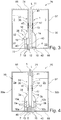
- FIG. 3 shows an evaporator tank unit 26 with an evaporator cartridge 1 with a provided on the shell side 31 of the base 14 mandrel 32, which may be provided for holding a capillary element 33 within a liquid tank 30.
- the mandrel 32 can serve as a holding and / or fastening element 38 and ensure a displacement-resistant and / or torsion-proof mounting of the evaporator insert 1 in the liquid tank 30.
- the mandrel 32 may also be formed entirely as a collar on the shell side 31 of the base part 14.
- the mandrel 32 or the lip is advantageously narrower than the section of the base with the largest circumference or as the bottom plate 7 associated collar to allow mounting of the evaporator cartridge 1 by insertion into the liquid tank 30.
- the capillary element 33 is configured to store liquid 2 and supply it to the liquid supply element 16.
- the use of a capillary element 33 or a porous medium permits storage and / or buffer storage of liquid 2 at a location defined by the capillary element 33, independently of the orientation and / or the level of the liquid tank 30 or the cartridge.
- the capillary element 33 extends at least partially and / or completely within the liquid tank 30.
- FIGS. 4 and 5 show an evaporator tank unit 26 with several, here for example two chambers 30a, 30b in a liquid tank 30 and an evaporator insert 1 with here two evaporators 3a, 3b, two liquid openings 15a, 15b, two Liquidzu slaughter instituten 16a, 16b and two liquid streams 6a, 6b, which the evaporators 3a, 3b, two preferably different liquids 2a, 2b from the chambers 30a, 30b for evaporation.
- the liquid tank 30 is segmented in this example by a partition wall 43 and adapted to store various liquids 2a, 2b.
- any tank geometry can be used in which partition walls 43 are provided for separating the liquids 2a, 2b.
- a plurality of liquid feed elements 16a, 16b are arranged offset in the circumferential direction of the base part 14 on the base part 14 and communicate with the liquid opening 15 or a plurality of liquid openings 15a, 15b.
- the LiquidzuZAijnemia 16a, 16b may be arranged in the circumferential direction at equal intervals or equal angular intervals to allow a uniform supply of liquid from the liquid tank 30 and / or the chambers 30a, 30b.
- the Liquidzutagenemia 16a, 16b may be arranged along the flow channel 13 in one embodiment.
- the liquid tank 30 may be unitary and may include the chambers 30a, 30b separated by the partition 43.
- the liquid tank 30 may be multi-parted and separate chambers 30a, 30b may be independently insertable into the evaporator tank unit 26.
- FIG. 4 shows a longitudinal section and FIG. 5 a cross-section through a radial plane of the evaporator tank unit 26.
- the section illustrates that the base member 14 is preferably disposed radially within the housing 37 of the or liquid tank 30 and the chambers 30a, 30b.
- any number or plurality of evaporators 3a, 3b may be provided in the evaporator insert 1, which via its respective liquid feed element 16a, 16b may comprise one or more chambers 2a, 30b of one or more liquids 2a, 2b can evaporate.
- a standardized evaporator assembly including carrier material having the evaporators 3a, 3b can preferably be installed both in an evaporator insert 1, which is designed for use with a liquid 2 or with a plurality of liquids 2a, 2b.
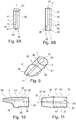
- FIGS. 6 and 7 show an evaporator tank unit 26 with a polygonal, for example hexagonal cross-section and an evaporator insert 1 used in the mounting channel 35.
- the outer shape of the liquid tank 30 and the housing 37 is independent of the shape of the evaporator insert first
- the evaporator insert 1 is inserted into the mounting channel 35 for mounting in an insertion opening 42 formed by the housing 37 of the liquid tank 30.
- the evaporator insert 1 is held against rotation in its operating position and non-displaceable.
- the evaporator insert 1 has several, here two holding and / or fastening elements 38 in this embodiment.
- a holding and / or fastening element 38 is arranged in the region of the chimney 40 and formed as a recess in the base part 14.
- the recess may also be provided at other positions on the shell side 31 of the base part 14, as long as the inner surface 36 of the mounting channel 35 has a corresponding bulge to allow a positive connection between the liquid tank 30 and evaporator insert 1.
- the base part 14 has a sectionally circular cross section, which tapers downstream between the chimney 40 and vent 41.
- the base part 14 tapers from the base plate 7 monotone.
- the taper of the shell side 31 of the base 14 causes a stop which prevents the arbitrary displacement along the longitudinal axis L of the evaporator cartridge 1 or along the mounting channel 35.
- the taper can thus be understood as a holding and / or fastener 38.
- the evaporator insert 1 has a wreath-like widening at the end assigned to the bottom plate 7.
- FIG. 8 shows an evaporator tank unit 26 with a round cross-section and illustrates different, possible and non-terminating shapes of the liquid reservoir 30 with the same connection and installation of the evaporator cartridge first
- FIGS. 9 to 11 show an evaporator tank unit 26, with a mouth end 39 on which a consumer can inhale.
- the vent 41 or the base part 14 and the air duct 13 extends to the mouth end 39.
- the mouth end 39 associated end face 11 is aligned with the mouth end 39th
- the base 14 encloses the air duct 13 completely.
- the air channel may be at least partially formed by the housing of the liquid tank 30 or the inner surface 36 of the mounting channel 35 and / or an extension of the inner surface 36.
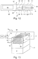
- FIG. 12 2 shows a schematic representation of an inhaler 27.
- the inhaler 27, here an electronic cigarette product comprises an inhaler housing 51, in which an air channel 52 is provided between at least one air inlet opening 57 and one air outlet opening 24 at a mouth end 39 of the cigarette product 27.
- the Mouth end 39 of the cigarette product 27 designates the end at which the consumer pulls for the purpose of inhalation, thereby applying a negative pressure to the cigarette product 27 and creating an air flow 53 in the air channel 52.
- the air flow 53 causes an air flow 5 through the flow channel 13 of the evaporator cartridge first
- the cigarette product 27 advantageously comprises a base part 69 and a consumption unit 26 with a liquid tank 30 and an evaporator insert 1.
- the consumption unit may be designed in particular in the form of an exchangeable cartridge, or in the form of a liquid tank 30 in which the consumer can use the evaporator insert 1.
- the air sucked in through the air inlet port 57 is led to the evaporator cartridge 1 in the air passage 52.
- the evaporator insert 1 is connected or connectable to at least one liquid tank 30, in which at least one liquid 2 is stored.
- the evaporator insert 1 evaporates liquid 2, which is supplied to it from the liquid tank 30, and gives the vaporized liquid 2 as an aerosol / vapor on an outlet side at an end face 11 of the evaporator insert 1 in the air flow 53 to.
- An advantageous volume of the liquid tank 30 is in the range between 0.1 ml and 5 ml, preferably between 0.5 ml and 3 ml, more preferably between 0.7 ml and 2 ml or 1.5 ml.
- the draw resistance can be defined via the air inlet opening 57 or an air feed, for example at the air inlet opening 57 facing end face 12 of the evaporator insert 1.
- the air supply is provided on the end face 12 or in an opening of a bottom plate 7 of the evaporator cartridge 1.
- the draw resistance can continue through correspondingly shaped holes or air inlet openings and formations in the flow channel 13 of the evaporator cartridge 1 are affected.
- the electronic cigarette 27 further includes an electrical energy storage 55 and an electronic control device 56.
- the energy storage 55 is usually arranged in the base part 69 and can in particular a disposable electrochemical battery or a rechargeable electrochemical battery, such as a lithium-ion battery , be.
- the electronic control device 56 comprises at least one digital data processing device, in particular microprocessor and / or microcontroller, in the base part 69 and / or in the consumption unit 26.
- the base part 69 expediently comprises an electronic interface 70 which, when the evaporator tank unit 26 is inserted, makes contact the electrical contacts 10 is arranged and arranged.
- the electronic control device 56 and the evaporator insert 1 are thus advantageously via the electronic interface 70 with the exemplary in FIGS. 1 to 4 shown electrical contacts 10 of the consumption unit connected or connectable.
- a sensor for example a vacuum sensor 46 or a pressure or flow switch, is advantageously arranged in the inhaler housing 51, wherein the control device 56 can determine on the basis of a sensor signal output by the vacuum sensor 46 that a consumer is pulling at the mouth end 29 of the cigarette product 27, to inhale.
- the in FIGS. 1 to 4 shown electronic unit 4 adapted to control the evaporator 3, when the negative pressure sensor 46 measures a negative by pulling negative pressure.
- the vacuum sensor 46 may provide a signal to the controller 56 to enable train activation of the vaporizer cartridge 1.
- the control device 56 controls, for example, the Evaporator insert 1, to add liquid 2 from the liquid tank 30 as an aerosol / vapor in the air flow 53.
- the liquid 2 to be metered stored in the liquid tank 30 is, for example, a mixture of 1,2-propylene glycol, glycerol, water, at least one flavor and / or at least one active ingredient, in particular nicotine.
- Other active ingredients and liquid mixtures, for example for medical applications, are not excluded.
- the consumption unit or cartridge advantageously comprises a non-volatile data memory for storing information or parameters relating to the consumption unit or cartridge.
- the data memory may be part of the electronic control device 56.
- the data memory is advantageously connected or connectable via contacts and / or lines to the control device 56 and / or the electronic unit 4.
- the evaporator insert 1 preferably comprises the air supply, the air duct, the steam discharge with possible recondensation treatment, a loading and / or venting devices 17, pre- and / or post-treatment areas 18, a unique electronic identification and / or electrical contacts 10 by default, so that all important functions a cartouche for the Inhaler 27 can be met, which can be integrated into versatile as possible liquid tank 30.
- FIG. 13 shows a schematic representation of an advantageous, exemplary embodiment of an evaporator 3.
- Other evaporator forms such as film evaporators are also possible.
- a film evaporator for example, at least partially form the base part 14.
- the exemplary evaporator 3 comprises a block-shaped, preferably monolithic heating element 60 made of an electrically conductive material, preferably silicon, doped ceramic, metal-ceramic, filter ceramic, semiconductor, in particular germanium, graphite, semi-metal and / or metal. It is not necessary that the entire heater 60 is made of an electrically conductive material. It may be sufficient, for example, that the surface of the heating element 60 is electrically conductive, for example metallic, coated. In this case, the entire surface need not be coated, for example, conductor tracks may be provided on a non-conductive base body.
- the heater 60 may also have a structure perforated by, for example, laser processing.
- the radiator 60 is provided with a plurality of microchannels 62 which fluidly connect an inlet side 61 of the radiator 60 to an outlet side 64.
- the inlet side 61 is connected in a fluid-conducting manner with the liquid tank 30 via a wick structure or a liquid feed element 16.
- the Liquidzu firedelement 16 is used for the passive delivery of liquid 2 from a liquid tank 30 to the radiator 60 by means of capillary forces to provide for a reliable aerosol production by the or the evaporator 3 at any time a sufficient supply of liquid.
- the Liquidzu firedelement 16 In the contact region or the inlet side 61 to the radiator 60 is the Liquidzudite 16 to evenly distribute liquid 2 to be temperature resistant and form with their relatively small pores and / or thin capillaries a kind of check valve to unwanted back flow of bubble-containing liquid 2 from the radiator 60 in the Liquidzuseasonedelement 16 and / or in the liquid tank 30 to prevent.
- the mean diameter of the microchannels 62 is preferably in the range between 5 ⁇ m and 200 ⁇ m, more preferably in the range between 30 ⁇ m and 150 ⁇ m, even more preferably in the range between 50 ⁇ m and 100 ⁇ m. Due to these dimensions, a capillary action is advantageously produced so that liquid entering the microchannel 62 at the inlet side 61 rises through the microchannel 62 up to the outlet side 64 until the microchannel 62 is filled with liquid.
- the volume ratio of microchannels 62 to heater 60 which may be referred to as the porosity of the heater 60, for example, in the range between 10% and 50%, preferably in the range between 15% and 40%, more preferably in the range between 20% and 30 %, for example 25%.
- the edge lengths of the surfaces provided with microchannels 62 of the heating element 60 are for example in the range between 0.5 mm and 3 mm, preferably between 0.5 mm and 1 mm.
- the dimensions of the surfaces of the heating element 60 provided with microchannels 62 may be, for example: 0.95 mm ⁇ 1.75 mm or 1.9 mm ⁇ 1.75 mm or 1.9 mm ⁇ 0.75 mm.
- the edge lengths of the heating element 60 may be, for example, in the range between 0.5 mm and 5 mm, preferably in the range between 0.75 mm and 4 mm, more preferably in the range between 1 mm and 3 mm.
- the area of the heater body 60 (chip size) may be, for example, 1 mm ⁇ 3 mm, 2 mm ⁇ 2 mm, or 2 mm ⁇ 3 mm.
- the width b of the heater 60 is preferably in the range between 1 mm and 5 mm, more preferably in the range between 2 mm and 4 mm, and is for example 3 mm.
- the height h of the radiator 60 is preferably in the range between 0.05 mm and 1 mm, more preferably in the range between 0.1 mm and 0.75 mm, even more preferably in the range between 0.2 mm and 0.5 mm, and is for example 0.3 mm.
- the number of microchannels 62 is preferably in the range between four and 1000. In this way, the heat input into the microchannels 62 can be optimized and realize a secure high evaporation performance and a sufficiently large steam outlet surface.
- the microchannels 62 are arranged in the form of a square, rectangular, polygonal, round, oval or other shaped array.
- the array may be in the form of a matrix with s columns and z rows, where s advantageously in the range between 2 and 50 and more advantageously in the range between 3 and 30 and / or z advantageously in the range between 2 and 50 and more advantageously in the range between 3 and 30. In this way, an effective and easily manufacturable arrangement of the microchannels 62 can be realized with a reliably high evaporation rate.
- the cross-section of the microchannels 62 may be square, rectangular, polygonal, round, oval or otherwise shaped, and / or may change in sections in the longitudinal direction, in particular increase, decrease or remain constant.
- the microchannels 62 may also have bionic structures with a particularly large surface area.
- the length of one or each microchannel 62 is preferably in the range between 100 ⁇ m and 1000 ⁇ m, more preferably in the range between 150 microns and 750 microns, more preferably in the range between 180 microns and 500 microns and is for example 300 microns. In this way, an optimal fluid intake and portion formation can be realized with sufficiently good heat input from the heater 60 into the microchannels 62.
- the distance between two microchannels 62 is preferably at least 1.3 times the clear diameter of a microchannel 62, the distance being based on the central axes of the two microchannels 62.
- the distance may preferably be 1.5 to 5 times, more preferably 2 to 4 times the clear diameter of a microchannel 62. In this way, an optimal heat input into the microchannels and a sufficiently stable arrangement and wall thickness of the microchannels can be realized.
- the evaporator insert 1 has a heating voltage source 71 which is preferably controllable by the control device 56 and which is connected to the latter via electrodes 72 on opposite sides of the heating element 60, so that an electrical voltage Uh generated by the heating voltage source 71 leads to a flow of current through the heating element 60. Due to the ohmic resistance of the electrically conductive heating element 60, the flow of current leads to heating of the heating element 60 (Joule heat) and therefore to evaporation of liquid contained in the microchannels 62. The radiator 60 thus acts as an evaporator. Vapor / aerosol generated in this manner escapes to the outlet side 64 from the microchannels 62 and is admixed with the airflow 5 in the flow channel 13, see FIG.
- the controller 56 controls the heating voltage source 71, by spontaneous heating driving the liquid in the microchannels 62 out of the microchannels 62 in the form of vapor / aerosol.
- the duration of the individual evaporation steps at different temperatures and / or evaporation of the individual components of the individual portions of the liquid can be kept so short and / or clocked with a drive frequency that the gradual evaporation of a consumer not perceived and still a largely homogeneous , tasteful, repeatable precise aerosol formation can be guaranteed.
- evaporation of a lower-boiling component of the liquid in a first evaporation interval at a first temperature A and then evaporation of a higher-boiling component of the liquid in a second evaporation interval at a second temperature B, which exceeds the temperature A are advantageous.
- a voltage curve Uh (t) adapted to the liquid mixture used is stored in the data memory of the inhaler 27.
- the evaporation temperature is preferably in the range between 100 ° C and 400 ° C, more preferably between 150 C and 350 ° C, even more preferably between 190 C and 290 C.
- a porous and / or capillary, liquid-conducting wick structure or the Liquidzuzhouelement 16 is arranged on the inlet side 61 of the radiator 60.
- the Liquidzuditeelement 16 contacts the inlet side 61 of the radiator 60 area and covers all the micro-channels 62 inlet side, as in the FIG. 13 is apparent.
- the liquid supply element 16 is liquid-conducting with the liquid tank 30 connected on the side opposite the heating element 60.
- the in the FIGS. 12 and 13 shown direct connection of the liquid tank 30 to the Liquidzufriedelement 16 is only to be understood as an example.
- a liquid interface and / or a plurality of liquid lines between liquid tank 30 and the Liquidzufriedelement 16 may be provided.
- the liquid tank 30 can therefore also be arranged at a distance from the liquid feed element 16.
- the liquid tank 30 may be larger in size than the LiquidzuGermanelement 16.
- the LiquidzuGermanelement 16 may for example be inserted into a feed opening 45 of a housing 37 of the liquid tank 30.
- a plurality of evaporators 3 may also be assigned to a liquid tank 30.
- the Liquidzu Switzerlandelement 16 may be arranged in the base part 14 and / or the bottom plate 7 of the evaporator cartridge 1.
- the Liquidzudite 16 may generally be in one piece or in several parts.
- the Liquidzu firedelement 16 consists of porous and / or capillary material, which is due to capillary forces in a position capable of passively evaporate liquid evaporated by the heater 60 in sufficient quantity from the liquid tank 30 to the radiator 60 to a drainage of the microchannels 62 and from it prevent resulting problems.
- the Liquidzu Switzerlandelement 16 is advantageously made of a non-conductive material to prevent unwanted heating of liquid in the Liquidzu Publishedelement 16 by electrical current flow. If the Liquidzufriedelement 16 is made of a conductive material, which is not excluded, between the the Liquidzufriedelement 16 and the radiator 60 advantageously an insulating layer of an electrically and / or thermally insulating material, such as glass, ceramic or plastic, with it through the insulating layer extending, provided with the micro-channels 62 through holes.
- an electrically and / or thermally insulating material such as glass, ceramic or plastic
- the Liquidzu Switzerlandelement 16 advantageously consists of one or more of the materials cotton, cellulose, acetate, glass fiber fabric, glass fiber ceramic, sintered ceramic, ceramic paper, aluminosilicate paper, metal foam, metal sponge, another heat-resistant, porous and / or capillary material with a suitable delivery rate, or a Composite of two or more of the aforementioned materials.
- the Liquidzufriedelement 16 may be a classic wick in one embodiment.
- the liquid supply element 16 may comprise at least one ceramic fiber paper and / or a porous ceramic.
- the volume of the wick structure 19 is preferably in the range between 1 mm 3 and 10 mm 3 , more preferably in the range between 2 mm 3 and 8 mm 3 , even more preferably in the range between 3 mm 3 and 7 mm 3 and is for example 5 mm 3 ,
- the heating element 60 can advantageously be produced from sections of a wafer with thin-film technology which has a layer thickness of preferably less than or equal to 1000 ⁇ m, more preferably less than or equal to 750 ⁇ m, even more preferably less than or equal to 500 ⁇ m. Surfaces of the heater 60 may advantageously be hydrophilic.
- the inlet side 61 and / or the outlet side 64 of the heating element 60 can advantageously be microstructured or have micro-grooves.
- the evaporator insert 1 is adjusted so that an amount of liquid preferably in the range between 1 .mu.l and 20 .mu.l, more preferably between 2 .mu.l and 10 .mu.l, even more preferably between 3 .mu.l and 5 .mu.l, typically 4 .mu.l per train of the consumer, is added.
- the evaporator insert 1 can be adjustable with respect to the amount of liquid / vapor per train.
- FIG. 14 shows a longitudinal section through an evaporator insert 1 with a secondary air duct 80.
- the evaporator insert 1 comprises a
- the separation wall 80 preferably runs in sections parallel to the longitudinal axis L of the evaporator insert 1.
- the separation wall 81 may, for example, be tubular or hollow cylindrical and / or be connected to an inner wall of the base part 13.
- the separation wall 81 and / or the secondary air duct 80 advantageously extends through the entire evaporator insert 1.
- a secondary air flow which can be conducted through the secondary air duct 80 can be sensed by a negative pressure sensor 46 provided in the inhaler 27.
- FIG. 15 shows a production technology advantageous evaporator tank unit 26.
- the evaporator tank unit 26 has in this example, a housing 37 with an insertion opening 42 and an outlet opening 74, but no inner wall 36 and no mounting channel 35.
- the evaporator insert 1 is guided with the outlet-side end face 11 to the outlet opening 74, in particular pushed so that the base part 14 and the shell side 31 closes the outlet opening 74 liquid-tight.
- the shape of the base part 14 results in a filling opening 73 arranged between the base part 14 and the insertion opening 42.
- the liquid tank 30 can be filled with liquid not shown in the figure via the filling opening 73.
- the evaporator insert 1 is guided up to a stop by the insertion opening 42, in particular pushed, so that the base part 14 and the shell side 31 closes the insertion opening 42 liquid-tight, thus providing a filled and leak-free evaporator tank unit 26.
- the evaporator insert 1 In the assembled state of the evaporator tank unit 26, the evaporator insert 1 extends through the insertion opening 42 to the Exit port 74.
- the vent 41 of the evaporator cartridge 1 protrudes from the exit port 74.
- the vent 74 is trimmed to align with the end face 65 of the housing 37 and the liquid tank 30, respectively.
- the above-described filling for the liquid tank 30 is not mandatory.
- the evaporator tank unit 26 can be fully assembled and the tank 30 can be filled via a corresponding filling opening.
- Other types of filling are possible.
Landscapes
- Health & Medical Sciences (AREA)
- Engineering & Computer Science (AREA)
- Life Sciences & Earth Sciences (AREA)
- Animal Behavior & Ethology (AREA)
- Anesthesiology (AREA)
- Biomedical Technology (AREA)
- Heart & Thoracic Surgery (AREA)
- Hematology (AREA)
- Veterinary Medicine (AREA)
- Public Health (AREA)
- General Health & Medical Sciences (AREA)
- Pulmonology (AREA)
- Bioinformatics & Cheminformatics (AREA)
- Disinfection, Sterilisation Or Deodorisation Of Air (AREA)
- Filling Or Discharging Of Gas Storage Vessels (AREA)
- Air Humidification (AREA)
Priority Applications (2)
| Application Number | Priority Date | Filing Date | Title |
|---|---|---|---|
| PL19169757T PL3560363T3 (pl) | 2018-04-27 | 2019-04-17 | Wkład parownikowy, jednostka parownik-zbiornik dla inhalatora, inhalator, oraz sposób wytwarzania |
| EP21156003.2A EP3834642B1 (fr) | 2018-04-27 | 2019-04-17 | Insertion d'évaporateur, unité de réservoir d'évaporateur pour un inhalateur, inhalateur ainsi que procédé de fabrication |
Applications Claiming Priority (1)
| Application Number | Priority Date | Filing Date | Title |
|---|---|---|---|
| DE102018206647.7A DE102018206647A1 (de) | 2018-04-27 | 2018-04-27 | Verdampfereinsatz, Verdampfer-Tank-Einheit für einen Inhalator, Inhalator, sowie Verfahren zur Fertigung |
Related Child Applications (2)
| Application Number | Title | Priority Date | Filing Date |
|---|---|---|---|
| EP21156003.2A Division EP3834642B1 (fr) | 2018-04-27 | 2019-04-17 | Insertion d'évaporateur, unité de réservoir d'évaporateur pour un inhalateur, inhalateur ainsi que procédé de fabrication |
| EP21156003.2A Division-Into EP3834642B1 (fr) | 2018-04-27 | 2019-04-17 | Insertion d'évaporateur, unité de réservoir d'évaporateur pour un inhalateur, inhalateur ainsi que procédé de fabrication |
Publications (3)
| Publication Number | Publication Date |
|---|---|
| EP3560363A1 true EP3560363A1 (fr) | 2019-10-30 |
| EP3560363B1 EP3560363B1 (fr) | 2021-03-24 |
| EP3560363B2 EP3560363B2 (fr) | 2024-08-14 |
Family
ID=66217891
Family Applications (2)
| Application Number | Title | Priority Date | Filing Date |
|---|---|---|---|
| EP21156003.2A Active EP3834642B1 (fr) | 2018-04-27 | 2019-04-17 | Insertion d'évaporateur, unité de réservoir d'évaporateur pour un inhalateur, inhalateur ainsi que procédé de fabrication |
| EP19169757.2A Active EP3560363B2 (fr) | 2018-04-27 | 2019-04-17 | Insertion d'évaporateur, unité de réservoir d'évaporateur pour un inhalateur, inhalateur ainsi que procédé de fabrication |
Family Applications Before (1)
| Application Number | Title | Priority Date | Filing Date |
|---|---|---|---|
| EP21156003.2A Active EP3834642B1 (fr) | 2018-04-27 | 2019-04-17 | Insertion d'évaporateur, unité de réservoir d'évaporateur pour un inhalateur, inhalateur ainsi que procédé de fabrication |
Country Status (7)
| Country | Link |
|---|---|
| US (1) | US20190328039A1 (fr) |
| EP (2) | EP3834642B1 (fr) |
| JP (1) | JP7091281B2 (fr) |
| KR (1) | KR20190125176A (fr) |
| CN (1) | CN110403245B (fr) |
| DE (1) | DE102018206647A1 (fr) |
| PL (1) | PL3560363T3 (fr) |
Cited By (4)
| Publication number | Priority date | Publication date | Assignee | Title |
|---|---|---|---|---|
| EP3574779A3 (fr) * | 2018-05-28 | 2020-03-04 | Hauni Maschinenbau GmbH | Dispositif pour un inhalateur |
| CN113156050A (zh) * | 2021-05-12 | 2021-07-23 | 中国烟草总公司郑州烟草研究院 | 一种评价雪茄烟卷制均匀度的系统及方法 |
| US11571529B2 (en) | 2018-05-28 | 2023-02-07 | Körber Technologies Gmbh | Arrangement and base part for an inhaler, and an inhaler |
| EP3841895B1 (fr) | 2019-02-18 | 2023-05-03 | Körber Technologies GmbH | Insert d'évaporateur pour un inhalateur, en particulier un produit de cigarette électronique, unité de réservoir d'évaporateur et produit de cigarette électronique |
Families Citing this family (22)
| Publication number | Priority date | Publication date | Assignee | Title |
|---|---|---|---|---|
| US11179538B2 (en) * | 2017-09-29 | 2021-11-23 | General Electric Company | Systems for anesthetic agent vaporization |
| DE102017123870B4 (de) * | 2017-10-13 | 2019-05-09 | Hauni Maschinenbau Gmbh | Verdampfereinheit für einen Inhalator, insbesondere für ein elektronisches Zigarettenprodukt |
| DE102018127926A1 (de) * | 2018-07-09 | 2020-01-09 | Hauni Maschinenbau Gmbh | Verdampferkopf für einen Inhalator, insbesondere für ein elektronisches Zigarettenprodukt |
| PL4094794T3 (pl) * | 2018-07-23 | 2026-05-04 | Juul Labs, Inc. | Kierowanie przepływem powietrza dla urządzenia odparowującego |
| US12256784B2 (en) | 2018-10-17 | 2025-03-25 | Juul Labs, Inc. | Cartridge for a vaporizer device |
| DE102019202063B4 (de) | 2019-02-15 | 2025-07-17 | Körber Technologies Gmbh | Docht-Heizer-Einheit für einen Inhalator |
| DE102019103989A1 (de) | 2019-02-18 | 2020-08-20 | Hauni Maschinenbau Gmbh | Verbrauchseinheit, Inhalator und Herstellungsverfahren |
| CN109770438B (zh) * | 2019-03-25 | 2023-07-25 | 云南中烟工业有限责任公司 | 一种镀膜硅基电子烟雾化芯片及其制备方法 |
| CA3139320A1 (fr) * | 2019-05-07 | 2020-11-12 | Loto Labs, Inc. | Structure de prevention de fuite dans un dispositif vaporisateur |
| DE102019116725A1 (de) * | 2019-06-20 | 2020-12-24 | Hauni Maschinenbau Gmbh | Verdampferkartusche sowie Inhalator mit einer solchen Verdampferkartusche |
| DE102019132109B4 (de) * | 2019-11-27 | 2021-07-29 | Hauni Maschinenbau Gmbh | Verfahren zum Herstellen von Dochtorgan-Heizorgan-Anordnungen als Verdampfereinheit zum Einsatz in einer Verdampferkartusche, Verdampfereinheit, Verdampferkartusche mit einer solchen Verdampfereinheit sowie Inhalator mit einer solchen Verdampferkartusche |
| JP7502854B2 (ja) * | 2019-12-05 | 2024-06-19 | 三菱鉛筆株式会社 | カートリッジ |
| CN112931957B (zh) * | 2019-12-10 | 2023-05-12 | 深圳市合元科技有限公司 | 用于气雾生成装置的感受器、气雾生成装置 |
| WO2021128163A1 (fr) * | 2019-12-26 | 2021-07-01 | 深圳麦克韦尔科技有限公司 | Dispositif de vaporisation électronique et vaporisateur associé |
| CA3181865A1 (fr) * | 2020-07-29 | 2022-02-03 | Andrew Robert John ROGAN | Ensemble evaporateur |
| CA3186470A1 (fr) * | 2020-07-29 | 2022-02-03 | Alec WRIGHT | Composant de vaporisation d'un dispositif de generation de vapeur |
| CN114847527A (zh) * | 2021-01-20 | 2022-08-05 | 深圳市合元科技有限公司 | 雾化器及电子雾化装置 |
| CN114617306B (zh) * | 2022-01-26 | 2025-09-30 | 深圳雪雾科技有限公司 | 电源组件及电子雾化装置 |
| JP2026506397A (ja) * | 2023-02-20 | 2026-02-24 | フィリップ・モーリス・プロダクツ・ソシエテ・アノニム | 傾斜壁付きカートリッジ |
| US20240415183A1 (en) * | 2023-06-15 | 2024-12-19 | Aspire North America Llc | Atomization tube |
| US12268807B1 (en) | 2023-12-20 | 2025-04-08 | Yale University | Devices, systems, and methods for providing individualized delivery of suspended medication |
| CN221949231U (zh) * | 2024-01-31 | 2024-11-05 | 尼科创业贸易有限公司 | 气溶胶供应系统的烟弹及气压可调节的气溶胶供应系统 |
Citations (4)
| Publication number | Priority date | Publication date | Assignee | Title |
|---|---|---|---|---|
| EP3020292A1 (fr) * | 2014-11-14 | 2016-05-18 | Shenzhen First Union Technology Co., Ltd. | Dispositif d'atomisation et cigarette electronique comportant celui-ci |
| WO2017185051A1 (fr) * | 2016-04-22 | 2017-10-26 | Pax Labs, Inc. | Dispositifs aérosol ayant des matériaux compartimentés |
| WO2018024742A1 (fr) * | 2016-08-01 | 2018-02-08 | Philip Morris Products S.A. | Cartouche et dispositif de vapotage comportant un dispositif de chauffage à serpentin |
| DE102016114718A1 (de) | 2016-08-09 | 2018-02-15 | Hauni Maschinenbau Gmbh | Inhalator und Flüssigkeitsspeicher für einen Inhalator |
Family Cites Families (37)
| Publication number | Priority date | Publication date | Assignee | Title |
|---|---|---|---|---|
| CA2082080A1 (fr) * | 1992-04-20 | 1993-10-21 | Gordon Walter Culp | Surface a plusieurs cavites thermocommandees individuellement |
| US20060196968A1 (en) | 2005-02-17 | 2006-09-07 | Rabin Barry H | Controlled formation of vapor and liquid droplet jets from liquids |
| CN101843368A (zh) | 2010-04-02 | 2010-09-29 | 陈志平 | 电子雾化吸入器的吸嘴 |
| US9445629B2 (en) * | 2011-01-12 | 2016-09-20 | Vaporgenie Llc | Vaporization pipe with improved filter unit |
| KR101081481B1 (ko) | 2011-06-13 | 2011-11-08 | 김형윤 | 전자담배용 무화기 일체형 카트리지 |
| US8528569B1 (en) | 2011-06-28 | 2013-09-10 | Kyle D. Newton | Electronic cigarette with liquid reservoir |
| KR101293859B1 (ko) * | 2012-03-02 | 2013-08-07 | 박선순 | 액상 공급관 및 도가니를 포함한 전자 담배 무화기 구조체 |
| US9161573B2 (en) | 2013-01-15 | 2015-10-20 | Huizhou Kimree Technology Co., Ltd., Shenzhen Branch | Electronic cigarette |
| CN203467677U (zh) * | 2013-09-25 | 2014-03-12 | 卓尔悦(常州)电子科技有限公司 | 电子烟透明雾化器 |
| CN103960782B (zh) | 2013-09-29 | 2016-09-21 | 深圳麦克韦尔股份有限公司 | 电子烟 |
| CN203523811U (zh) * | 2013-09-29 | 2014-04-09 | 深圳市麦克韦尔科技有限公司 | 电子烟 |
| CN103653260B (zh) * | 2013-12-04 | 2015-12-30 | 林光榕 | 无棉电子烟的雾化装置 |
| US9801415B2 (en) * | 2014-07-11 | 2017-10-31 | POSIFA Microsytems, Inc. | MEMS vaporizer |
| CN104197549B (zh) * | 2014-09-22 | 2016-05-25 | 文力 | 有蒸发器和换热器的太阳能制热器 |
| CN204444245U (zh) | 2015-01-05 | 2015-07-08 | 深圳市合元科技有限公司 | 可更换的雾化单元和包括该雾化单元的雾化器及电子烟 |
| CN204599335U (zh) | 2015-02-05 | 2015-09-02 | 惠州市吉瑞科技有限公司 | 雾化组件及电子烟 |
| EP3153037B1 (fr) * | 2015-02-06 | 2020-05-06 | O-Net Automation Technology Shenzhen Limited | Atomiseur de cigarette électronique |
| CN107404942A (zh) | 2015-03-02 | 2017-11-28 | 惠州市吉瑞科技有限公司 | 雾化器及电子烟 |
| CN107404943A (zh) | 2015-03-17 | 2017-11-28 | 惠州市吉瑞科技有限公司 | 雾化器和电子烟 |
| EP3085257B1 (fr) * | 2015-04-22 | 2019-06-05 | Fontem Holdings 1 B.V. | Dispositif à fumer électronique |
| DE102015107082A1 (de) * | 2015-05-06 | 2016-11-10 | Joachim Fischer | Elektronische Zigarette zum Verdampfen zweier Liquide |
| US10039320B2 (en) | 2015-05-14 | 2018-08-07 | Lunatech, Llc | Multi-chambered vaporizer and blend control |
| US10524505B2 (en) * | 2015-08-06 | 2020-01-07 | Altria Client Services Llc. | Method for measuring a vapor precursor level in a cartomizer of an electronic vaping device and/or an electronic vaping device configured to perform the method |
| WO2017031472A1 (fr) * | 2015-08-19 | 2017-02-23 | David Guo | Cigarette électronique et son atomiseur vaporisateur |
| CN205143486U (zh) | 2015-09-02 | 2016-04-13 | 深圳市合元科技有限公司 | 雾化头、雾化器及电子烟 |
| CN205197001U (zh) * | 2015-11-25 | 2016-05-04 | 深圳市合元科技有限公司 | 分体式雾化器、电子烟及便于更换的储液装置 |
| DE102016002665A1 (de) | 2016-03-08 | 2017-09-14 | Hauni Maschinenbau Gmbh | Elektronisches Zigarettenprodukt und Kartusche für ein elektronisches Zigarettenprodukt |
| US10375993B2 (en) * | 2016-03-21 | 2019-08-13 | Altria Client Services Llc | E-vaping device cartridge with internal infrared sensor |
| CN105661652A (zh) * | 2016-04-20 | 2016-06-15 | 深圳市新宜康科技有限公司 | 可更换加热器的环保电子烟雾化芯 |
| KR102510184B1 (ko) | 2016-06-20 | 2023-03-15 | 필립모리스 프로덕츠 에스.에이. | 에어로졸 발생 시스템용 증발기 조립체 |
| US10463077B2 (en) | 2016-06-24 | 2019-11-05 | Altria Client Services Llc | Cartridge for e-vaping device with open-microchannels |
| US9795169B1 (en) † | 2016-07-05 | 2017-10-24 | Xiaochun Zhu | Replaceable vaporizer assembly and electronic cigarette having the same |
| CN106418703A (zh) * | 2016-09-06 | 2017-02-22 | 深圳市合元科技有限公司 | 电子烟及其雾化器 |
| CN206182355U (zh) * | 2016-09-08 | 2017-05-24 | 深圳市合元科技有限公司 | 电子烟及其雾化器 |
| CN206333368U (zh) * | 2016-11-02 | 2017-07-18 | 廖向阳 | 雾化芯 |
| CN206238429U (zh) * | 2016-12-02 | 2017-06-13 | 湖南酷伯新晶电子科技有限公司 | 电子烟加热装置、电子烟雾化器和电子烟 |
| CN207084113U (zh) | 2017-06-06 | 2018-03-13 | 深圳麦克韦尔股份有限公司 | 一种用于电子烟的雾化器以及具有该雾化器的电子烟 |
-
2018
- 2018-04-27 DE DE102018206647.7A patent/DE102018206647A1/de active Pending
-
2019
- 2019-03-27 US US16/366,346 patent/US20190328039A1/en not_active Abandoned
- 2019-04-15 KR KR1020190043795A patent/KR20190125176A/ko not_active Ceased
- 2019-04-17 EP EP21156003.2A patent/EP3834642B1/fr active Active
- 2019-04-17 EP EP19169757.2A patent/EP3560363B2/fr active Active
- 2019-04-17 PL PL19169757T patent/PL3560363T3/pl unknown
- 2019-04-26 CN CN201910345322.2A patent/CN110403245B/zh active Active
- 2019-04-26 JP JP2019084872A patent/JP7091281B2/ja not_active Expired - Fee Related
Patent Citations (4)
| Publication number | Priority date | Publication date | Assignee | Title |
|---|---|---|---|---|
| EP3020292A1 (fr) * | 2014-11-14 | 2016-05-18 | Shenzhen First Union Technology Co., Ltd. | Dispositif d'atomisation et cigarette electronique comportant celui-ci |
| WO2017185051A1 (fr) * | 2016-04-22 | 2017-10-26 | Pax Labs, Inc. | Dispositifs aérosol ayant des matériaux compartimentés |
| WO2018024742A1 (fr) * | 2016-08-01 | 2018-02-08 | Philip Morris Products S.A. | Cartouche et dispositif de vapotage comportant un dispositif de chauffage à serpentin |
| DE102016114718A1 (de) | 2016-08-09 | 2018-02-15 | Hauni Maschinenbau Gmbh | Inhalator und Flüssigkeitsspeicher für einen Inhalator |
Cited By (4)
| Publication number | Priority date | Publication date | Assignee | Title |
|---|---|---|---|---|
| EP3574779A3 (fr) * | 2018-05-28 | 2020-03-04 | Hauni Maschinenbau GmbH | Dispositif pour un inhalateur |
| US11571529B2 (en) | 2018-05-28 | 2023-02-07 | Körber Technologies Gmbh | Arrangement and base part for an inhaler, and an inhaler |
| EP3841895B1 (fr) | 2019-02-18 | 2023-05-03 | Körber Technologies GmbH | Insert d'évaporateur pour un inhalateur, en particulier un produit de cigarette électronique, unité de réservoir d'évaporateur et produit de cigarette électronique |
| CN113156050A (zh) * | 2021-05-12 | 2021-07-23 | 中国烟草总公司郑州烟草研究院 | 一种评价雪茄烟卷制均匀度的系统及方法 |
Also Published As
| Publication number | Publication date |
|---|---|
| EP3834642B1 (fr) | 2023-08-23 |
| JP7091281B2 (ja) | 2022-06-27 |
| EP3560363B1 (fr) | 2021-03-24 |
| EP3560363B2 (fr) | 2024-08-14 |
| EP3834642A1 (fr) | 2021-06-16 |
| JP2019188151A (ja) | 2019-10-31 |
| US20190328039A1 (en) | 2019-10-31 |
| CN110403245A (zh) | 2019-11-05 |
| DE102018206647A1 (de) | 2019-10-31 |
| CN110403245B (zh) | 2022-05-13 |
| KR20190125176A (ko) | 2019-11-06 |
| PL3560363T3 (pl) | 2021-09-13 |
Similar Documents
| Publication | Publication Date | Title |
|---|---|---|
| EP3834642B1 (fr) | Insertion d'évaporateur, unité de réservoir d'évaporateur pour un inhalateur, inhalateur ainsi que procédé de fabrication | |
| DE102017123869B4 (de) | Flüssigkeitsspeicher für einen Inhalator, insbesondere für ein elektronisches Zigarettenprodukt | |
| EP3694353B1 (fr) | Cartouche de liquide destinée à un inhalateur, notamment à un produit cigarette électronique | |
| EP3694352B1 (fr) | Unité vaporisateur destinée à un inhalateur, notamment à un produit cigarette électronique | |
| EP3695733B1 (fr) | Insert d'évaporateur pour un inhalateur, en particulier un produit de cigarette électronique, unité de réservoir d'évaporateur et produit de cigarette électronique | |
| EP3762150B1 (fr) | Procédé de fabrication d'un corps chauffant à commande électrique pour un inhalateur | |
| DE102018127926A1 (de) | Verdampferkopf für einen Inhalator, insbesondere für ein elektronisches Zigarettenprodukt | |
| EP3923752B2 (fr) | Unité vaporisateur-réservoir pour un inhalateur, de préférence un produit de cigarette électronique, produit de cigarette électronique et structure de mèche | |
| DE102018130106B4 (de) | Verdampfervorrichtung, Verbrauchseinheit, Inhalator und Verfahren zur Herstellung von elektrisch beheizbaren Heizkörpern und Dichtungsträgern | |
| EP3927196B1 (fr) | Dispositif vaporisateur pour inhalateur, unité de consommation, inhalateur et procédé de fabrication | |
| DE102019103989A1 (de) | Verbrauchseinheit, Inhalator und Herstellungsverfahren | |
| DE102019103988A1 (de) | Verdampfervorrichtung für einen Inhalator, Verbrauchseinheit, Inhalator und Herstellungsverfahren | |
| EP3593657B1 (fr) | Unité d'évaporateur pour un inhalateur, en particulier pour un produit de cigarette électronique | |
| WO2020260241A2 (fr) | Inhalateur et réservoir de liquide remplaçable pour un inhalateur |
Legal Events
| Date | Code | Title | Description |
|---|---|---|---|
| PUAI | Public reference made under article 153(3) epc to a published international application that has entered the european phase |
Free format text: ORIGINAL CODE: 0009012 |
|
| STAA | Information on the status of an ep patent application or granted ep patent |
Free format text: STATUS: THE APPLICATION HAS BEEN PUBLISHED |
|
| AK | Designated contracting states |
Kind code of ref document: A1 Designated state(s): AL AT BE BG CH CY CZ DE DK EE ES FI FR GB GR HR HU IE IS IT LI LT LU LV MC MK MT NL NO PL PT RO RS SE SI SK SM TR |
|
| AX | Request for extension of the european patent |
Extension state: BA ME |
|
| STAA | Information on the status of an ep patent application or granted ep patent |
Free format text: STATUS: REQUEST FOR EXAMINATION WAS MADE |
|
| 17P | Request for examination filed |
Effective date: 20191217 |
|
| RBV | Designated contracting states (corrected) |
Designated state(s): AL AT BE BG CH CY CZ DE DK EE ES FI FR GB GR HR HU IE IS IT LI LT LU LV MC MK MT NL NO PL PT RO RS SE SI SK SM TR |
|
| GRAP | Despatch of communication of intention to grant a patent |
Free format text: ORIGINAL CODE: EPIDOSNIGR1 |
|
| STAA | Information on the status of an ep patent application or granted ep patent |
Free format text: STATUS: GRANT OF PATENT IS INTENDED |
|
| RIC1 | Information provided on ipc code assigned before grant |
Ipc: A61M 15/06 20060101ALI20200930BHEP Ipc: A24F 47/00 20200101AFI20200930BHEP Ipc: A61M 11/04 20060101ALI20200930BHEP |
|
| INTG | Intention to grant announced |
Effective date: 20201019 |
|
| GRAS | Grant fee paid |
Free format text: ORIGINAL CODE: EPIDOSNIGR3 |
|
| GRAA | (expected) grant |
Free format text: ORIGINAL CODE: 0009210 |
|
| STAA | Information on the status of an ep patent application or granted ep patent |
Free format text: STATUS: THE PATENT HAS BEEN GRANTED |
|
| AK | Designated contracting states |
Kind code of ref document: B1 Designated state(s): AL AT BE BG CH CY CZ DE DK EE ES FI FR GB GR HR HU IE IS IT LI LT LU LV MC MK MT NL NO PL PT RO RS SE SI SK SM TR |
|
| REG | Reference to a national code |
Ref country code: GB Ref legal event code: FG4D Free format text: NOT ENGLISH |
|
| REG | Reference to a national code |
Ref country code: CH Ref legal event code: EP |
|
| REG | Reference to a national code |
Ref country code: IE Ref legal event code: FG4D Free format text: LANGUAGE OF EP DOCUMENT: GERMAN |
|
| REG | Reference to a national code |
Ref country code: DE Ref legal event code: R096 Ref document number: 502019001036 Country of ref document: DE Ref country code: AT Ref legal event code: REF Ref document number: 1373570 Country of ref document: AT Kind code of ref document: T Effective date: 20210415 |
|
| REG | Reference to a national code |
Ref country code: CH Ref legal event code: NV Representative=s name: FREIGUTPARTNERS GMBH, CH |
|
| REG | Reference to a national code |
Ref country code: DE Ref legal event code: R026 Ref document number: 502019001036 Country of ref document: DE |
|
| PLBI | Opposition filed |
Free format text: ORIGINAL CODE: 0009260 |
|
| 26 | Opposition filed |
Opponent name: ARUTYUNOVA, NATALIA Effective date: 20210512 |
|
| REG | Reference to a national code |
Ref country code: NL Ref legal event code: FP |
|
| REG | Reference to a national code |
Ref country code: LT Ref legal event code: MG9D |
|
| PG25 | Lapsed in a contracting state [announced via postgrant information from national office to epo] |
Ref country code: BG Free format text: LAPSE BECAUSE OF FAILURE TO SUBMIT A TRANSLATION OF THE DESCRIPTION OR TO PAY THE FEE WITHIN THE PRESCRIBED TIME-LIMIT Effective date: 20210624 Ref country code: HR Free format text: LAPSE BECAUSE OF FAILURE TO SUBMIT A TRANSLATION OF THE DESCRIPTION OR TO PAY THE FEE WITHIN THE PRESCRIBED TIME-LIMIT Effective date: 20210324 Ref country code: FI Free format text: LAPSE BECAUSE OF FAILURE TO SUBMIT A TRANSLATION OF THE DESCRIPTION OR TO PAY THE FEE WITHIN THE PRESCRIBED TIME-LIMIT Effective date: 20210324 Ref country code: GR Free format text: LAPSE BECAUSE OF FAILURE TO SUBMIT A TRANSLATION OF THE DESCRIPTION OR TO PAY THE FEE WITHIN THE PRESCRIBED TIME-LIMIT Effective date: 20210625 Ref country code: NO Free format text: LAPSE BECAUSE OF FAILURE TO SUBMIT A TRANSLATION OF THE DESCRIPTION OR TO PAY THE FEE WITHIN THE PRESCRIBED TIME-LIMIT Effective date: 20210624 |
|
| PG25 | Lapsed in a contracting state [announced via postgrant information from national office to epo] |
Ref country code: RS Free format text: LAPSE BECAUSE OF FAILURE TO SUBMIT A TRANSLATION OF THE DESCRIPTION OR TO PAY THE FEE WITHIN THE PRESCRIBED TIME-LIMIT Effective date: 20210324 Ref country code: LV Free format text: LAPSE BECAUSE OF FAILURE TO SUBMIT A TRANSLATION OF THE DESCRIPTION OR TO PAY THE FEE WITHIN THE PRESCRIBED TIME-LIMIT Effective date: 20210324 Ref country code: SE Free format text: LAPSE BECAUSE OF FAILURE TO SUBMIT A TRANSLATION OF THE DESCRIPTION OR TO PAY THE FEE WITHIN THE PRESCRIBED TIME-LIMIT Effective date: 20210324 |
|
| PG25 | Lapsed in a contracting state [announced via postgrant information from national office to epo] |
Ref country code: LT Free format text: LAPSE BECAUSE OF FAILURE TO SUBMIT A TRANSLATION OF THE DESCRIPTION OR TO PAY THE FEE WITHIN THE PRESCRIBED TIME-LIMIT Effective date: 20210324 Ref country code: CZ Free format text: LAPSE BECAUSE OF FAILURE TO SUBMIT A TRANSLATION OF THE DESCRIPTION OR TO PAY THE FEE WITHIN THE PRESCRIBED TIME-LIMIT Effective date: 20210324 Ref country code: EE Free format text: LAPSE BECAUSE OF FAILURE TO SUBMIT A TRANSLATION OF THE DESCRIPTION OR TO PAY THE FEE WITHIN THE PRESCRIBED TIME-LIMIT Effective date: 20210324 Ref country code: SM Free format text: LAPSE BECAUSE OF FAILURE TO SUBMIT A TRANSLATION OF THE DESCRIPTION OR TO PAY THE FEE WITHIN THE PRESCRIBED TIME-LIMIT Effective date: 20210324 |
|
| PG25 | Lapsed in a contracting state [announced via postgrant information from national office to epo] |
Ref country code: IS Free format text: LAPSE BECAUSE OF FAILURE TO SUBMIT A TRANSLATION OF THE DESCRIPTION OR TO PAY THE FEE WITHIN THE PRESCRIBED TIME-LIMIT Effective date: 20210724 Ref country code: SK Free format text: LAPSE BECAUSE OF FAILURE TO SUBMIT A TRANSLATION OF THE DESCRIPTION OR TO PAY THE FEE WITHIN THE PRESCRIBED TIME-LIMIT Effective date: 20210324 Ref country code: PT Free format text: LAPSE BECAUSE OF FAILURE TO SUBMIT A TRANSLATION OF THE DESCRIPTION OR TO PAY THE FEE WITHIN THE PRESCRIBED TIME-LIMIT Effective date: 20210726 Ref country code: RO Free format text: LAPSE BECAUSE OF FAILURE TO SUBMIT A TRANSLATION OF THE DESCRIPTION OR TO PAY THE FEE WITHIN THE PRESCRIBED TIME-LIMIT Effective date: 20210324 |
|
| PLBI | Opposition filed |
Free format text: ORIGINAL CODE: 0009260 |
|
| PG25 | Lapsed in a contracting state [announced via postgrant information from national office to epo] |
Ref country code: LU Free format text: LAPSE BECAUSE OF NON-PAYMENT OF DUE FEES Effective date: 20210417 |
|
| 26 | Opposition filed |
Opponent name: G.D S.P.A. Effective date: 20211215 |
|
| PLAX | Notice of opposition and request to file observation + time limit sent |
Free format text: ORIGINAL CODE: EPIDOSNOBS2 |
|
| PG25 | Lapsed in a contracting state [announced via postgrant information from national office to epo] |
Ref country code: ES Free format text: LAPSE BECAUSE OF FAILURE TO SUBMIT A TRANSLATION OF THE DESCRIPTION OR TO PAY THE FEE WITHIN THE PRESCRIBED TIME-LIMIT Effective date: 20210324 Ref country code: MC Free format text: LAPSE BECAUSE OF FAILURE TO SUBMIT A TRANSLATION OF THE DESCRIPTION OR TO PAY THE FEE WITHIN THE PRESCRIBED TIME-LIMIT Effective date: 20210324 Ref country code: DK Free format text: LAPSE BECAUSE OF FAILURE TO SUBMIT A TRANSLATION OF THE DESCRIPTION OR TO PAY THE FEE WITHIN THE PRESCRIBED TIME-LIMIT Effective date: 20210324 Ref country code: AL Free format text: LAPSE BECAUSE OF FAILURE TO SUBMIT A TRANSLATION OF THE DESCRIPTION OR TO PAY THE FEE WITHIN THE PRESCRIBED TIME-LIMIT Effective date: 20210324 |
|
| PG25 | Lapsed in a contracting state [announced via postgrant information from national office to epo] |
Ref country code: SI Free format text: LAPSE BECAUSE OF FAILURE TO SUBMIT A TRANSLATION OF THE DESCRIPTION OR TO PAY THE FEE WITHIN THE PRESCRIBED TIME-LIMIT Effective date: 20210324 |
|
| PG25 | Lapsed in a contracting state [announced via postgrant information from national office to epo] |
Ref country code: IE Free format text: LAPSE BECAUSE OF NON-PAYMENT OF DUE FEES Effective date: 20210417 |
|
| PLBB | Reply of patent proprietor to notice(s) of opposition received |
Free format text: ORIGINAL CODE: EPIDOSNOBS3 |
|
| PG25 | Lapsed in a contracting state [announced via postgrant information from national office to epo] |
Ref country code: IS Free format text: LAPSE BECAUSE OF FAILURE TO SUBMIT A TRANSLATION OF THE DESCRIPTION OR TO PAY THE FEE WITHIN THE PRESCRIBED TIME-LIMIT Effective date: 20210724 |
|
| REG | Reference to a national code |
Ref country code: DE Ref legal event code: R081 Ref document number: 502019001036 Country of ref document: DE Owner name: KOERBER TECHNOLOGIES GMBH, DE Free format text: FORMER OWNER: HAUNI MASCHINENBAU GMBH, 21033 HAMBURG, DE |
|
| REG | Reference to a national code |
Ref country code: NL Ref legal event code: HC Owner name: KOERBER TECHNOLOGIES GMBH; DE Free format text: DETAILS ASSIGNMENT: CHANGE OF OWNER(S), CHANGE OF OWNER(S) NAME; FORMER OWNER NAME: HAUNI MASCHINENBAU GMBH Effective date: 20221031 |
|
| RAP4 | Party data changed (patent owner data changed or rights of a patent transferred) |
Owner name: KOERBER TECHNOLOGIES GMBH |
|
| REG | Reference to a national code |
Ref country code: BE Ref legal event code: HC Owner name: KOERBER TECHNOLOGIES GMBH; DE Free format text: DETAILS ASSIGNMENT: CHANGE OF OWNER(S), CHANGE OF OWNER(S) NAME Effective date: 20221028 |
|
| REG | Reference to a national code |
Ref country code: AT Ref legal event code: HC Ref document number: 1373570 Country of ref document: AT Kind code of ref document: T Owner name: KOERBER TECHNOLOGIES GMBH, DE Effective date: 20230228 |
|
| REG | Reference to a national code |
Ref country code: BE Ref legal event code: HC Owner name: KOERBER TECHNOLOGIES GMBH; DE Free format text: DETAILS ASSIGNMENT: CHANGE OF OWNER(S), CHANGE OF OWNER(S) NAME; FORMER OWNER NAME: HAUNI MASCHINENBAU GMBH Effective date: 20230321 |
|
| PG25 | Lapsed in a contracting state [announced via postgrant information from national office to epo] |
Ref country code: CY Free format text: LAPSE BECAUSE OF FAILURE TO SUBMIT A TRANSLATION OF THE DESCRIPTION OR TO PAY THE FEE WITHIN THE PRESCRIBED TIME-LIMIT Effective date: 20210324 |
|
| P01 | Opt-out of the competence of the unified patent court (upc) registered |
Effective date: 20230616 |
|
| PG25 | Lapsed in a contracting state [announced via postgrant information from national office to epo] |
Ref country code: HU Free format text: LAPSE BECAUSE OF FAILURE TO SUBMIT A TRANSLATION OF THE DESCRIPTION OR TO PAY THE FEE WITHIN THE PRESCRIBED TIME-LIMIT; INVALID AB INITIO Effective date: 20190417 |
|
| APAH | Appeal reference modified |
Free format text: ORIGINAL CODE: EPIDOSCREFNO |
|
| APBM | Appeal reference recorded |
Free format text: ORIGINAL CODE: EPIDOSNREFNO |
|
| APBP | Date of receipt of notice of appeal recorded |
Free format text: ORIGINAL CODE: EPIDOSNNOA2O |
|
| APBU | Appeal procedure closed |
Free format text: ORIGINAL CODE: EPIDOSNNOA9O |
|
| PLBJ | Opposition found inadmissible |
Free format text: ORIGINAL CODE: 0009275 |
|
| PG25 | Lapsed in a contracting state [announced via postgrant information from national office to epo] |
Ref country code: MK Free format text: LAPSE BECAUSE OF FAILURE TO SUBMIT A TRANSLATION OF THE DESCRIPTION OR TO PAY THE FEE WITHIN THE PRESCRIBED TIME-LIMIT Effective date: 20210324 |
|
| REG | Reference to a national code |
Ref country code: CH Ref legal event code: PK Free format text: DIE PUBLIKATION VOM 17.04.2024 WURDE AM 24.04.2024 IRRTUEMLICHERWEISE ERNEUT PUBLIZIERT. LA PUBLICATION DU 17.04.2024 A ETE REPUBLIEE PAR ERREUR LE 24.04.2024. LA PUBBLICAZIONE DEL 17.04.2024 E STATA ERRONEAMENTE RIPUBBLICATA IL 24.04.2024. |
|
| 26U | Opposition found inadmissible |
Opponent name: ARUTYUNOVA, NATALIA Effective date: 20230926 |
|
| PGFP | Annual fee paid to national office [announced via postgrant information from national office to epo] |
Ref country code: NL Payment date: 20240425 Year of fee payment: 6 |
|
| PGFP | Annual fee paid to national office [announced via postgrant information from national office to epo] |
Ref country code: PL Payment date: 20240322 Year of fee payment: 6 |
|
| PUAH | Patent maintained in amended form |
Free format text: ORIGINAL CODE: 0009272 |
|
| STAA | Information on the status of an ep patent application or granted ep patent |
Free format text: STATUS: PATENT MAINTAINED AS AMENDED |
|
| PGFP | Annual fee paid to national office [announced via postgrant information from national office to epo] |
Ref country code: CH Payment date: 20240501 Year of fee payment: 6 |
|
| PGFP | Annual fee paid to national office [announced via postgrant information from national office to epo] |
Ref country code: AT Payment date: 20240423 Year of fee payment: 6 |
|
| PGFP | Annual fee paid to national office [announced via postgrant information from national office to epo] |
Ref country code: IT Payment date: 20240426 Year of fee payment: 6 |
|
| 27A | Patent maintained in amended form |
Effective date: 20240814 |
|
| AK | Designated contracting states |
Kind code of ref document: B2 Designated state(s): AL AT BE BG CH CY CZ DE DK EE ES FI FR GB GR HR HU IE IS IT LI LT LU LV MC MK MT NL NO PL PT RO RS SE SI SK SM TR |
|
| REG | Reference to a national code |
Ref country code: DE Ref legal event code: R102 Ref document number: 502019001036 Country of ref document: DE |
|
| PGFP | Annual fee paid to national office [announced via postgrant information from national office to epo] |
Ref country code: BE Payment date: 20240423 Year of fee payment: 6 |
|
| PG25 | Lapsed in a contracting state [announced via postgrant information from national office to epo] |
Ref country code: MT Free format text: LAPSE BECAUSE OF FAILURE TO SUBMIT A TRANSLATION OF THE DESCRIPTION OR TO PAY THE FEE WITHIN THE PRESCRIBED TIME-LIMIT Effective date: 20210324 |
|
| PG25 | Lapsed in a contracting state [announced via postgrant information from national office to epo] |
Ref country code: NL Free format text: LAPSE BECAUSE OF FAILURE TO SUBMIT A TRANSLATION OF THE DESCRIPTION OR TO PAY THE FEE WITHIN THE PRESCRIBED TIME-LIMIT Effective date: 20210324 |
|
| PG25 | Lapsed in a contracting state [announced via postgrant information from national office to epo] |
Ref country code: NL Free format text: LAPSE BECAUSE OF FAILURE TO SUBMIT A TRANSLATION OF THE DESCRIPTION OR TO PAY THE FEE WITHIN THE PRESCRIBED TIME-LIMIT Effective date: 20210324 |
|
| PGFP | Annual fee paid to national office [announced via postgrant information from national office to epo] |
Ref country code: DE Payment date: 20250430 Year of fee payment: 7 |
|
| PGFP | Annual fee paid to national office [announced via postgrant information from national office to epo] |
Ref country code: GB Payment date: 20250426 Year of fee payment: 7 |
|
| PGFP | Annual fee paid to national office [announced via postgrant information from national office to epo] |
Ref country code: FR Payment date: 20250426 Year of fee payment: 7 |
|
| REG | Reference to a national code |
Ref country code: CH Ref legal event code: H13 Free format text: ST27 STATUS EVENT CODE: U-0-0-H10-H13 (AS PROVIDED BY THE NATIONAL OFFICE) Effective date: 20251125 |
|
| PG25 | Lapsed in a contracting state [announced via postgrant information from national office to epo] |
Ref country code: TR Free format text: LAPSE BECAUSE OF FAILURE TO SUBMIT A TRANSLATION OF THE DESCRIPTION OR TO PAY THE FEE WITHIN THE PRESCRIBED TIME-LIMIT Effective date: 20210324 |
|
| REG | Reference to a national code |
Ref country code: AT Ref legal event code: MM01 Ref document number: 1373570 Country of ref document: AT Kind code of ref document: T Effective date: 20250417 |
|
| REG | Reference to a national code |
Ref country code: BE Ref legal event code: MM Effective date: 20250430 |
|
| PG25 | Lapsed in a contracting state [announced via postgrant information from national office to epo] |
Ref country code: AT Free format text: LAPSE BECAUSE OF NON-PAYMENT OF DUE FEES Effective date: 20250417 |
|
| PG25 | Lapsed in a contracting state [announced via postgrant information from national office to epo] |
Ref country code: BE Free format text: LAPSE BECAUSE OF NON-PAYMENT OF DUE FEES Effective date: 20250430 |
|
| PG25 | Lapsed in a contracting state [announced via postgrant information from national office to epo] |
Ref country code: CH Free format text: LAPSE BECAUSE OF NON-PAYMENT OF DUE FEES Effective date: 20250430 |
|
| PG25 | Lapsed in a contracting state [announced via postgrant information from national office to epo] |
Ref country code: IT Free format text: LAPSE BECAUSE OF NON-PAYMENT OF DUE FEES Effective date: 20250417 |