EP3560435B1 - Dispositifs, système et procédés permettant de fournir un accès chirurgical et de faciliter la fermeture d'ouvertures d'accès chirurgical - Google Patents
Dispositifs, système et procédés permettant de fournir un accès chirurgical et de faciliter la fermeture d'ouvertures d'accès chirurgical Download PDFInfo
- Publication number
- EP3560435B1 EP3560435B1 EP19170620.9A EP19170620A EP3560435B1 EP 3560435 B1 EP3560435 B1 EP 3560435B1 EP 19170620 A EP19170620 A EP 19170620A EP 3560435 B1 EP3560435 B1 EP 3560435B1
- Authority
- EP
- European Patent Office
- Prior art keywords
- actuator rod
- distal
- proximal
- jaw member
- suture passer
- Prior art date
- Legal status (The legal status is an assumption and is not a legal conclusion. Google has not performed a legal analysis and makes no representation as to the accuracy of the status listed.)
- Active
Links
- 238000000034 method Methods 0.000 title description 11
- 241000287107 Passer Species 0.000 claims description 67
- 210000001519 tissue Anatomy 0.000 description 44
- 239000012636 effector Substances 0.000 description 17
- 238000003780 insertion Methods 0.000 description 7
- 230000037431 insertion Effects 0.000 description 7
- 206010052428 Wound Diseases 0.000 description 5
- 208000027418 Wounds and injury Diseases 0.000 description 4
- 230000007704 transition Effects 0.000 description 4
- 238000000151 deposition Methods 0.000 description 3
- 210000003815 abdominal wall Anatomy 0.000 description 2
- 230000000881 depressing effect Effects 0.000 description 2
- 230000000694 effects Effects 0.000 description 2
- 210000003195 fascia Anatomy 0.000 description 2
- 239000000463 material Substances 0.000 description 2
- 210000003205 muscle Anatomy 0.000 description 2
- 238000001356 surgical procedure Methods 0.000 description 2
- 241001631457 Cannula Species 0.000 description 1
- 230000004888 barrier function Effects 0.000 description 1
- 238000001574 biopsy Methods 0.000 description 1
- 238000004140 cleaning Methods 0.000 description 1
- 230000000295 complement effect Effects 0.000 description 1
- 230000001419 dependent effect Effects 0.000 description 1
- 238000012976 endoscopic surgical procedure Methods 0.000 description 1
- 230000035876 healing Effects 0.000 description 1
- 230000002401 inhibitory effect Effects 0.000 description 1
- 208000014674 injury Diseases 0.000 description 1
- 210000004303 peritoneum Anatomy 0.000 description 1
- 230000008733 trauma Effects 0.000 description 1
- 230000001960 triggered effect Effects 0.000 description 1
Images




Classifications
-
- A—HUMAN NECESSITIES
- A61—MEDICAL OR VETERINARY SCIENCE; HYGIENE
- A61B—DIAGNOSIS; SURGERY; IDENTIFICATION
- A61B17/00—Surgical instruments, devices or methods
- A61B17/04—Surgical instruments, devices or methods for suturing wounds; Holders or packages for needles or suture materials
- A61B17/0469—Suturing instruments for use in minimally invasive surgery, e.g. endoscopic surgery
-
- A—HUMAN NECESSITIES
- A61—MEDICAL OR VETERINARY SCIENCE; HYGIENE
- A61B—DIAGNOSIS; SURGERY; IDENTIFICATION
- A61B17/00—Surgical instruments, devices or methods
- A61B17/04—Surgical instruments, devices or methods for suturing wounds; Holders or packages for needles or suture materials
- A61B17/0483—Hand-held instruments for holding sutures
-
- A—HUMAN NECESSITIES
- A61—MEDICAL OR VETERINARY SCIENCE; HYGIENE
- A61B—DIAGNOSIS; SURGERY; IDENTIFICATION
- A61B17/00—Surgical instruments, devices or methods
- A61B17/04—Surgical instruments, devices or methods for suturing wounds; Holders or packages for needles or suture materials
- A61B17/0482—Needle or suture guides
-
- A—HUMAN NECESSITIES
- A61—MEDICAL OR VETERINARY SCIENCE; HYGIENE
- A61B—DIAGNOSIS; SURGERY; IDENTIFICATION
- A61B17/00—Surgical instruments, devices or methods
- A61B17/04—Surgical instruments, devices or methods for suturing wounds; Holders or packages for needles or suture materials
- A61B17/0485—Devices or means, e.g. loops, for capturing the suture thread and threading it through an opening of a suturing instrument or needle eyelet
-
- A—HUMAN NECESSITIES
- A61—MEDICAL OR VETERINARY SCIENCE; HYGIENE
- A61B—DIAGNOSIS; SURGERY; IDENTIFICATION
- A61B17/00—Surgical instruments, devices or methods
- A61B17/04—Surgical instruments, devices or methods for suturing wounds; Holders or packages for needles or suture materials
- A61B17/06—Needles ; Sutures; Needle-suture combinations; Holders or packages for needles or suture materials
- A61B17/06066—Needles, e.g. needle tip configurations
-
- A—HUMAN NECESSITIES
- A61—MEDICAL OR VETERINARY SCIENCE; HYGIENE
- A61B—DIAGNOSIS; SURGERY; IDENTIFICATION
- A61B17/00—Surgical instruments, devices or methods
- A61B17/34—Trocars; Puncturing needles
- A61B17/3417—Details of tips or shafts, e.g. grooves, expandable, bendable; Multiple coaxial sliding cannulas, e.g. for dilating
- A61B17/3421—Cannulas
- A61B17/3423—Access ports, e.g. toroid shape introducers for instruments or hands
-
- A—HUMAN NECESSITIES
- A61—MEDICAL OR VETERINARY SCIENCE; HYGIENE
- A61B—DIAGNOSIS; SURGERY; IDENTIFICATION
- A61B17/00—Surgical instruments, devices or methods
- A61B2017/00367—Details of actuation of instruments, e.g. relations between pushing buttons, or the like, and activation of the tool, working tip, or the like
-
- A—HUMAN NECESSITIES
- A61—MEDICAL OR VETERINARY SCIENCE; HYGIENE
- A61B—DIAGNOSIS; SURGERY; IDENTIFICATION
- A61B17/00—Surgical instruments, devices or methods
- A61B17/04—Surgical instruments, devices or methods for suturing wounds; Holders or packages for needles or suture materials
- A61B17/0469—Suturing instruments for use in minimally invasive surgery, e.g. endoscopic surgery
- A61B2017/047—Suturing instruments for use in minimally invasive surgery, e.g. endoscopic surgery having at least one proximally pointing needle located at the distal end of the instrument, e.g. for suturing trocar puncture wounds starting from inside the body
-
- A—HUMAN NECESSITIES
- A61—MEDICAL OR VETERINARY SCIENCE; HYGIENE
- A61B—DIAGNOSIS; SURGERY; IDENTIFICATION
- A61B17/00—Surgical instruments, devices or methods
- A61B17/28—Surgical forceps
- A61B17/29—Forceps for use in minimally invasive surgery
- A61B2017/2901—Details of shaft
- A61B2017/2902—Details of shaft characterized by features of the actuating rod
Definitions
- the present disclosure relates to surgical access and closure of surgical access openings and, more particularly, to devices, systems, and methods that provide access to an internal surgical site through an opening in tissue and facilitate the closure of the opening in tissue.
- Puncture wounds may result from trauma or may be intentionally created in order to provide a surgical access opening for accessing an internal surgical site of a patient during surgical procedures.
- a trocar device is utilized to puncture the peritoneum to provide access by way of a cannula through the abdominal wall.
- a trocar and/or cannula is placed through the abdominal wall for introduction of surgical instrumentation which is necessary to carry out one or more surgical tasks.
- the surgeon may introduce a surgical instrument such as a forceps, scissors, clip applier, stapler, biopsy device, or any other suitable surgical instrument as necessary to complete a particular surgical task or tasks. Once the task(s) is complete, it is necessary to close the opening.
- WO-A-2017075752 discloses an endoscopic clip applier with an inner shaft member
- a suture passer is provided.
- the suture passer includes a handle assembly, a shaft extending distally from the handle assembly, a first jaw member coupled to a distal end portion of the shaft, a second jaw member pivotable relative to the first jaw member between open and closed configurations, and an overstroke assembly.
- the overstroke assembly includes a proximal actuator rod operably coupled to the handle assembly, a distal actuator rod axially movable relative to the shaft and operably coupled to the second jaw member, and a biasing member interposed between the proximal and distal actuator rods. Advancement of the proximal actuator rod in response to an actuation of the handle assembly advances the biasing member and the distal actuator rod.
- the biasing member is configured to compress to allow for independent movement of the proximal actuator rod relative to the distal actuator rod in response to an obstruction of the second jaw member.
- the overstroke assembly may further include a sleeve disposed within the shaft and longitudinally movable relative to the shaft.
- the sleeve may be disposed about the proximal and distal actuator rods and may house the biasing member.
- the sleeve may define a longitudinally-extending slot
- the proximal actuator rod may have a pin slidably received in the slot
- an actuation of the handle assembly may distally move the pin from a proximal position within the slot to a distal position within the slot.
- the proximal actuator rod may be configured to move relative to the sleeve and the distal actuator rod during the distal movement of the pin toward the distal position.
- the pin may be configured to proximally move the sleeve and the distal actuator rod to move the second jaw member toward the closed configuration in response to an actuation of the handle assembly.
- the distal actuator rod may be fixed within the sleeve, and the proximal actuator rod may be slip-fit within the sleeve.
- the second jaw member may have a proximal end portion pivotably coupled to the distal actuator rod.
- the first jaw member may have a distal tip configured to pierce tissue.
- the second jaw member may be nested with the first jaw member in the closed configuration.
- the first jaw member may define a recessed portion configured to receive the second jaw member when the second jaw member is in the closed configuration.
- each of the first and second jaw members may have a suture-contacting surface defining a transverse notch therein.
- the transverse notches of the first and second jaw members may be configured to cooperatively enclose a suture therein.
- a suture passer in another aspect of the present disclosure, includes a handle assembly, a shaft extending distally from the handle assembly, and an end effector assembly.
- the end effector assembly includes a first jaw member coupled to a distal end portion of the shaft and a second jaw member pivotable relative to the first jaw member between open and closed configurations.
- the suture passer further includes a proximal actuator rod, a distal actuator rod, and a biasing member interposed between the proximal and distal actuator rods.
- the proximal actuator rod is operably coupled to a trigger of the handle assembly, such that a first actuation of the trigger proximally moves the proximal actuator rod.
- the distal actuator rod is slidably disposed within the shaft and operably coupled to the second jaw member.
- the proximal actuator rod is configured to distally move the distal actuator rod via the biasing member in response to a second actuation of the handle assembly.
- the biasing member is configured to compress between the proximal and distal actuator rods upon the proximal actuator rod exerting a distally-oriented, threshold force on the biasing member.
- the distal actuator rod may be pivotably coupled to the second jaw member via a pivot pin configured to receive a distally-oriented force from the distal actuator rod.
- the distally-oriented, threshold force imparted on the biasing member may be lower than a threshold force required to damage the pivot pin.
- the second actuation of the trigger may distally move the proximal actuator rod relative to the distal actuator rod to compress the biasing member therebetween.
- the suture passer may further include a sleeve disposed within the shaft and longitudinally movable relative to the shaft.
- the sleeve may be disposed about the proximal and distal actuator rods and may house the biasing member.
- the sleeve may define a longitudinally-extending slot
- the proximal actuator rod may have a pin slidably received in the slot
- the second actuation of the trigger may distally move the pin from a proximal position within the slot to a distal position within the slot.
- the proximal actuator rod may be configured to move relative to the sleeve and the distal actuator rod during the distal movement of the pin toward the distal position.
- the pin may be configured to proximally move the sleeve and the distal actuator rod to move the second jaw member toward the closed configuration in response to the first actuation of the trigger.
- the distal actuator rod may be fixed within the sleeve, and the proximal actuator rod may be slip-fit within the sleeve.
- a method of depositing a portion of a suture into an internal surgical site and/or retrieving a portion of suture from within an internal surgical site includes advancing a suture passer into a surgical site while first and second jaw members of the suture passer are in a closed configuration; and actuating a handle assembly of the suture passer. Actuating the handle assembly one of: distally moves a proximal actuator rod toward a distal actuator rod; or distally moves the proximal actuator rod, the biasing member, and the distal actuator rod together. Distal movement of the proximal actuator rod toward the distal actuator rod compresses a biasing member between the proximal actuator rod and the distal actuator.
- the proximal actuator rod is operably coupled to the handle assembly and the distal actuator rod is operably coupled to the second jaw member. Distal movement of the proximal actuator rod, the biasing member, and the distal actuator rod together pivots the second jaw member relative to the first jaw member to transition the first and second jaw members to the open configuration for one of depositing a portion of suture into the internal surgical site or retrieving a portion of the suture from the internal surgical site.
- the biasing member may be compressed between the proximal and distal actuator rods when the second jaw member is in a constrained state as the handle assembly is being actuated.
- the proximal actuator rod, the biasing member, and the distal actuator rod may distally move together when the second jaw member is in an unconstrained state as the handle assembly is being actuated.
- the method may further include returning the suture passer to the closed condition; and withdrawing the suture passer from the internal surgical site.
- parallel and perpendicular are understood to include relative configurations that are substantially parallel and substantially perpendicular up to about + or - 10 degrees from true parallel and true perpendicular.
- the present disclosure provides devices, systems, and methods that facilitate accessing an internal surgical site through an opening in tissue, performing one or more minimally-invasive surgical tasks within the internal surgical site, and closing the opening in tissue once the surgical task(s) is complete.
- proximal will refer to the end of the device or portion thereof which is closest to the clinician during use
- distal will refer to the end or portion which is farthest from the clinician during use, as is traditional.
- the present disclosure provides a suture passer having an overstroke assembly that prevents damage to an end effector assembly of the suture passer when the end effector assembly is in a constrained state.
- the end effector assembly of the suture passer has a first jaw member, and a second jaw member movable relative to the first jaw member between an open configuration, and a closed configuration, in which the jaw members grasp a suture therebetween.
- the second jaw member of the suture passer may be prevented from opening due to an obstruction present in the surgical site (e.g., a surgical instrument, hard tissue, or the like).
- the overstroke assembly of the present disclosure includes a proximal actuator rod operably coupled to the handle assembly, a distal actuator rod operably coupled to the second jaw member, and a biasing member disposed between the proximal and distal actuator rods.
- the biasing member compresses between the proximal and distal actuator rods during an overstroke by the clinician to prevent the distal actuator rod from damaging a pivot member that couples the second jaw member with the distal actuator rod.
- the surgical assembly or wound closure system 10 generally includes a cannula 100, a guide member 200, and a suture passer 300.
- a trocar (not shown) may be first utilized to create and/or expand an opening in tissue and to subsequently position the cannula 100 therein; the cannula 100 is utilized to protect surrounding tissue, maintain insufflation, and/or guide surgical instrumentation (not shown) into an internal surgical site; the guide member 200 is inserted into the cannula 100 and utilized to facilitate insertion and withdrawal of the suture passer 300 through the tissue adjacent the opening; and the suture passer 300 is utilized to deposit and/or retrieve a portion of suture to/from the internal surgical site on either side of the opening in tissue to enable tying off of the suture to close the opening.
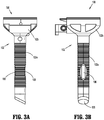
- the cannula 100 of the surgical assembly 10 ( FIG. 1 ) includes an elongated portion 102 and a housing 110.
- the elongated portion 102 includes an elongated tubular member 102a and a base member 102b.
- the base member 102b is configured to couple the housing 110 and the elongated portion 102 to one another.
- the elongated tubular member 102a extends distally from the base member 102b and may be formed from a translucent material, although other materials are also contemplated.
- the elongated tubular member 102a of the cannula 100 may be provided in various configurations, e.g., various diameters between about 10mm to about 15mm and/or various lengths from about 70mm to about 150mm, although other suitable configurations are also contemplated.
- the elongated tubular member 102a is configured for positioning within an opening in tissue and defines a longitudinal passageway 105 extending therethrough that is configured to receive surgical instrumentation (not shown) for guiding the surgical instrumentation (not shown) through the opening in tissue and into the internal surgical site.
- the passageway 105 of the elongated tubular member 102a is configured to receive the guide member 200 ( FIGS. 1 and 4 ) to facilitate closure of the opening in tissue after completion of the surgical procedure, as detailed below.
- the elongated portion 102 of the cannula 100 has a pair of opposed slots 106 extending through an annular side wall of the elongated tubular member 102a, thus providing lateral access to and from the longitudinal passageway 105 to and from the exterior of the elongated tubular member 102a.
- the opposed slots 106 may be positioned along the length of the elongated tubular member 102a at any suitable position, e.g., closer to or further from the base member 102b of the elongated portion 102 of the cannula 100.
- the slots 106 are located on the elongated tubular member 102a at a position distal of the skin and fatty layers of tissue and adjacent to the fascia and muscle layers of tissue. This is desirable because the fascia and muscle layers are better suited to receive and retain a suture for closing the opening in tissue.
- a cannula 100 having the slots 106 positioned to achieve this function may be selected.
- other configurations are also contemplated.
- the guide member 200 of the surgical assembly 10 is illustrated.
- the guide member 200 is configured for use with the cannula 100 to facilitate closure of an opening in tissue after completion of one or more surgical tasks. More specifically, the guide member 200 is configured for releasable engagement within the elongated portion 102 of the cannula 100 to guide passage of a suitable suture passer, e.g., suture passer 300 (see FIGS. 1 and 5-11 ), through an opening in tissue and into the internal surgical site to deposit and/or retrieve a portion of a suture, thus facilitating closure of the opening in the tissue.
- a suitable suture passer e.g., suture passer 300 (see FIGS. 1 and 5-11 .
- the guide member 200 generally includes a guide housing 210 disposed in mechanical cooperation with an elongated guide shaft 220.
- the guide member 200 further includes a pair of guide lumens 216a, 216b extending therethrough.
- the guide housing 210 defines a proximally-facing portion 211 including a pair of recesses 212 that facilitate grasping and manipulation of the guide member 200 and a pair of apertures 214a, 214b that communicate with the proximal ends of respective lumens 216a, 216b extending through the guide member 200.
- the guide housing 210 further includes threading 217 defined on a distally-facing portion 215 thereof that is configured to engage complementary threading 129 ( FIG.
- the elongated guide shaft 220 of the guide member 200 extends distally from the guide housing 210 and is configured for insertion through the passageway 105 ( FIG. 2 ) of the elongated tubular member 102a of the cannula 100 after having removed the housing 110 of the cannula 100 from the base member 102b of the cannula 100.
- the elongated shaft 220 includes a pair of opposed slots 226a ( FIG. 1 ), 226b ( FIG. 4 ) defined through the annular side wall of the elongated shaft 220 that communicate with the distal ends of respective lumens 216a, 216b extending through the guide member 200.
- the lumens 216a, 216b extend between respective apertures 214a, 214b defined through the proximally-facing portion 211 of the guide housing 210 and respective slots 226a, 226b defined through the annular side wall of the elongated shaft 220.
- a suture passer e.g., suture passer 300 ( FIG. 1 ) may then be inserted through one of the lumens 216a, 216b of the guide member 200, the corresponding slot 106 of the cannula 100, tissue, and into the internal surgical site to facilitate closure of the opening in tissue.
- the suture passer 300 is transitionable between an insertion/withdrawal/piercing condition ( FIGS. 1 , 5 , 7, 8 , and 11 ), and an expanded/deployed condition ( FIGS. 9 and 10 ) and includes an overstroke assembly 340 for effecting the transition between these conditions.
- the suture passer 300 generally includes a handle assembly 302, a shaft or tubular member 310 extending distally from the handle assembly 302, and an end effector assembly 320 coupled to a distal end portion 310b of the shaft 310.
- the handle assembly 302 has a fixed handle portion 304 and a trigger 306 pivotably coupled to the fixed handle portion 304.
- a clinician moves the trigger 306 of the handle assembly 302 in relation to the fixed handle portion 304 to approximate or space the trigger 306 and the fixed handle portion 304.
- the shaft 310 of the suture passer 300 may be flexible to permit insertion through any of the lumens 216a, 216b of the guide member 200.
- the shaft 310 may have a rigid, curved configuration having a radius of curvature equal to that of the lumens 216a, 216b of the guide member 200 for use therewith, or may have a rigid, linear configuration.
- the shaft 310 has a proximal end portion 310a fixed to the fixed handle portion 304 of the handle assembly 302.
- the shaft 310 serves as a barrier to inhibit contact between the internal components of the suture passer 300 and surgical instrumentation (not shown) and/or tissue through which the suture passer 300 is inserted, thus inhibiting rubbing or catching of the internal components of the suture passer 300 upon the surgical instrumentation (not shown) and/or tissue during actuation of the suture passer 300.
- the end effector assembly 320 of the suture passer 300 has a first jaw member 322 fixed to the distal end portion 310b of the shaft 310, and a second jaw member 324 coupled to the first jaw member 322 and configured to pivot relative to the first jaw member 322 between a closed configuration, as shown in FIG. 7 , and an open configuration, as shown in FIG. 10 .
- the first jaw member 322 has a proximal end portion 322a, an intermediate portion 322c, and a distal end portion 322b.
- the second jaw member 324 has a proximal end portion 324a and a distal end portion 324b.
- the intermediate portion 322c of the first jaw member 322 defines a recessed portion 328 dimensioned for receipt of the distal end portion 324b of the second jaw member 324 upon the second jaw member 324 entering the closed configuration.
- the distal end portion 324b of the second jaw member 324 is nested with the recessed portion 328 of the second jaw member 324, such that each of the first and second jaw members 322, 324 cooperatively assume a tubular configuration that is streamlined with the shaft 310 to facilitate passage of the end effector assembly 320 through the guide member 200 ( FIG. 4 ) and the cannula 100 ( FIG. 2 ).
- the distal end portion 322b of the first jaw member 322 may have a sharpened or pointed distal piercing tip 330 configured to facilitate piercing through tissue.
- the proximal end portion 322a of the first jaw member 322 and the proximal end portion 324a of the second jaw member 324 have a pivot pin 326 extending transversely therethrough to pivotably couple the second jaw member 324 to the first jaw member 322.
- the second jaw member 324 may be directly pivotably coupled to the distal end portion 310b of the shaft 310.
- the proximal end portion 324a of the second jaw member 324 may be set at an obtuse angle from the remainder of the second jaw member 324.
- the first and second jaw members 322, 324 each have a planar suture-contacting surface 334a, 334b opposing one another when the first and second jaw members 322, 324 are in the closed configuration.
- Each of the suture-contacting surfaces 334a, 334b defines a notch 336a, 336b therein that extends across the respective first and second jaw members 322, 324.
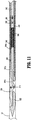
- the notches 336a, 336b of the first and second jaw members 322, 324 are configured to cooperatively define a channel 338 ( FIG. 8 ) to enclose a suture upon the first and second jaw members 322, 324 assuming the closed configuration, as shown in FIG. 11 .
- the suture passer 300 includes an overstroke assembly 340 movably received in the shaft 310 and configured to effect an actuation of the end effector assembly 320 while protecting components of the suture passer 300 (e.g., the actuation pin 313) from being damaged.
- the overstroke assembly 340 prevents damage to the suture passer 300 when the end effector assembly 320 is in a constrained state, i.e., when the second jaw member 324 is prevented from opening due to an obstruction "O" in a body cavity or in tissue ( FIG. 11 ).
- the overstroke assembly 340 includes a proximal actuator rod 342, a distal actuator rod 344, and a biasing member 346 interposed between the proximal and distal actuator rods 342, 344.
- the proximal actuator rod 342 is disposed within the shaft 310 and is longitudinally movable therein.
- the proximal actuator rod 342 has a proximal end portion 342a operably coupled to the trigger 306 of the handle assembly 302 ( FIG.
- a first actuation of the handle assembly 302 retracts the proximal actuator rod 342 within the shaft 310
- a second actuation of the handle assembly 302 e.g., a spacing of the trigger 306 from the fixed handle portion 304
- the proximal actuator rod 342 has a distal end portion 342b disposed within the distal end portion 310b of the shaft 310 and abuts a proximal end portion 346a of the biasing member 346.
- the distal end portion 342b of the proximal actuator rod 342 has a transversely-extending pin 348 axially fixed thereto, as will be described.
- the biasing member 346 may be a coil spring, with other types of biasing members being contemplated.
- the distal actuator rod 344 of the overstroke assembly 340 is disposed within the distal end portion 310b of the shaft 310 and is longitudinally movable therein.
- the distal actuator rod 344 has a proximal end portion 344a in abutting engagement with a distal end portion 346b of the biasing member 346, and a distal end portion 344b.
- the distal end portion 344b of the distal actuator rod 344 has a connector 350 set at an obtuse angle from the remainder of the distal actuator rod 344.
- the connector 350 rotationally couples the proximal end portion 324a of the second jaw member 324 to the distal actuator rod 344 via the actuation pin 313.
- distal movement of the distal actuator rod 344 transitions the second jaw member 324 toward the open configuration using the actuation pin 313 of the second jaw member 324.
- the overstroke assembly 340 may further include an outer sleeve 354 disposed within the shaft 310 and longitudinally movable therein.
- the sleeve 354 houses the biasing member 346 and has a proximal end portion 354a disposed about the distal end portion 342b of the proximal actuator rod 342, and a distal end portion 354b disposed about the proximal end portion 344a of the distal actuator rod 344.
- the proximal actuator rod 342 is slip fit within the sleeve 354, such that the proximal actuator rod 342 is movable relative to the sleeve 354, whereas the distal actuator rod 344 is press-fit within the sleeve 354, such that the sleeve 354 and the distal actuator rod 344 translate within the shaft 310 together during actuation of the suture passer 300.
- the sleeve 354 defines a pair of opposed longitudinally-extending slots 356 in the proximal end portion 354a thereof.
- the pin 348 of the proximal actuator rod 342 extends through the slots 356 of the sleeve 354 to permit translation of the proximal actuator rod 342 relative to the sleeve 354 between a proximal position, in which the pin 348 is engaged with a proximal limit 356a of the slots 356, and a distal position, in which the pin 348 is engaged with a distal limit 356b of the slots 356.
- a retraction of the proximal actuator rod 342 results in a retraction of the sleeve 354, and, in turn, the distal actuator rod 344 and the biasing member 346, to close the second jaw member 324.
- advancement of the proximal actuator rod 342 translates the pin 348 from the proximal position toward the distal position within the slots 356 of the sleeve 354, thereby compressing the biasing member 346 between the proximal actuator rod 342 and the distal actuator rod 344.
- advancement of the proximal actuator rod 342 urges the biasing member 346 with a sufficient amount of force (without compressing the biasing member 346) to advance the biasing member 346, the distal actuator rod 344, and the sleeve 354 as an integral unit, thereby opening the second jaw member 324.
- the second jaw member 324 of the suture passer 300 is disposed in the open configuration with the pin 348 of the proximal actuator rod 342 disposed in the proximal position relative to the slots 356 of the sleeve 354.
- a portion of suture may be positioned within or removed from the notches 336a, 336b of the first and second jaw members 322, 324.
- the suture passer 300 is transitioned to the insertion/withdrawal condition ( FIG. 8 ) by depressing or translating the trigger 306 distally relative to the fixed handle portion 304.
- Depressing the trigger 306 relative to the fixed handle portion 304 translates the proximal actuator rod 342 proximally relative to the shaft 310, thereby pulling the sleeve 354, the distal actuator rod 344, and the biasing member 346 proximally therewith as an integral unit. Since the actuation pin 313 of the distal actuator rod 344 is coupled to the second jaw member 324 at an offset location relative to the pivot pin 326, proximal translation of the actuation pin 313 of the distal actuator rod 344 rotates the second jaw member 324 toward the closed configuration, as shown in FIG. 8 .
- the suture passer 300 may be inserted through one of the lumens 226a, 226b of the guide member 200 ( FIG. 4 ) and into contact with tissue surrounding an opening in the tissue. Upon contacting tissue, the distal piercing tip 330 of the first jaw member 322 advances the tissue passer 300 through the tissue until reaching the internal surgical site. Once the suture passer 300 has been inserted through the guide member 200, tissue, and into the internal surgical site, the suture passer 300 may be returned to the open configuration ( FIGS. 9 and 10 ) by pulling or retracting the trigger 306 proximally away from the fixed handle portion 304.
- the suture passer 300 may be returned to the closed configuration ( FIGS. 1 , 5 , 7, 8 , and 11 ) as detailed above, and withdrawn from the internal surgical site. As the suture passer is withdrawn from the surgical site through tissue, the suture is pulled through the tissue to close the opening in the tissue.
- an attempt to transition the end effector assembly 320 to the open configuration via the second actuation of the handle assembly 302 fails due to the second jaw member 324 being constrained from opening due to an obstruction "O" ( FIG. 11 ) in the surgical site.
- a distally-oriented force applied on the biasing member 346 via the proximal actuator rod 342 overcomes the spring force of the biasing member 346 to compress the biasing member 346 between the proximal and distal actuator rods 342, 344.
- the pin 348 of the proximal actuator rod 342 is free to move distally relative to the sleeve 354 from the proximal position within the slots 356 of the sleeve 354 to the distal position within the slots 356 of the sleeve 354 throughout the entire second actuation of the handle assembly 302.
- the biasing member 346 rather than the actuation pin 313, absorbs the distally-oriented force originating from the clinician's second actuation of the handle assembly 302 to prevent damage to the actuation pin 313 and also to tissue at the surgical site.
- the entire distally-oriented force of the proximal actuator rod 342 would ultimately be absorbed by the actuation pin 313, which would likely shear under such force and prevent reuse of the suture passer 300.
- the suture passer 300 may be configured for selective disassembly (and be made of sterilizable reusable and/or disposable components) to facilitate cleaning and/or replacement of disposable components.
- any suitable suture or sutures may be utilized in conjunction with the above.
- the suture(s) may be provided in any suitable form and/or include any suitable feature(s) to facilitate insertion through and depositing the suture within the internal surgical site on one side of the opening in tissue, and retrieval and withdrawal of the portion of suture from the other side of the opening in tissue.
- Such a configuration establishes a "U"-shaped suture extending through tissue on either side of the opening and across the opening on the internal side of tissue. This configuration enables tying off of the externally-disposed free ends of the suture and provides sufficient holding strength to permit healing and resist re-opening of the sutured tissue.
Landscapes
- Health & Medical Sciences (AREA)
- Life Sciences & Earth Sciences (AREA)
- Surgery (AREA)
- Heart & Thoracic Surgery (AREA)
- Engineering & Computer Science (AREA)
- Biomedical Technology (AREA)
- Nuclear Medicine, Radiotherapy & Molecular Imaging (AREA)
- Medical Informatics (AREA)
- Molecular Biology (AREA)
- Animal Behavior & Ethology (AREA)
- General Health & Medical Sciences (AREA)
- Public Health (AREA)
- Veterinary Medicine (AREA)
- Pathology (AREA)
- Surgical Instruments (AREA)
Claims (13)
- Dispositif passeur de suture (300), comprenant :un ensemble poignée (302) ;un arbre (310) s'étendant de manière distale de l'ensemble poignée ;un premier élément de mâchoire (322) accouplé à une partie d'extrémité distale (310b) de l'arbre ;un second élément de mâchoire (324) pouvant pivoter par rapport au premier élément de mâchoire entre des configurations ouverte et fermée ; etun ensemble de surcourse (340) comportant :une tige d'actionnement proximale (342) accouplée de manière fonctionnelle à l'ensemble poignée ;une tige d'actionnement distale (344) mobile de manière axiale par rapport à l'arbre et accouplée de manière fonctionnelle au second élément de mâchoire ;un élément de sollicitation (346) interposé entre les tiges d'actionnement proximale et distale, dans lequel l'avancement de la tige d'actionnement proximale en réponse à un actionnement de l'ensemble poignée fait avancer l'élément de sollicitation et la tige d'actionnement distale, l'élément de sollicitation étant conçu pour se comprimer afin de permettre un mouvement indépendant de la tige d'actionnement proximale par rapport à la tige d'actionnement distale en réponse à une obstruction du second élément de mâchoire ; etun manchon (354) disposé à l'intérieur de l'arbre et mobile longitudinalement par rapport à l'arbre, le manchon étant disposé autour des tiges d'actionnement proximale et distale et logeant l'élément de sollicitation ;caractérisé en ce que la tige d'actionnement distale est fixée à l'intérieur du manchon, de telle sorte que le manchon (354) et la tige d'actionnement distale (344) se translatent ensemble à l'intérieur de l'arbre (310) pendant l'actionnement du dispositif passeur de suture, etla tige d'actionnement proximale est ajustée par glissement à l'intérieur du manchon, de telle sorte que la tige d'actionnement proximale (342) est mobile par rapport au manchon (354).
- Dispositif passeur de suture (300) selon la revendication 1, dans lequel le manchon (354) définit une fente s'étendant longitudinalement (356), la tige d'actionnement proximale (342) ayant une broche (348) reçue de manière coulissante dans la fente.
- Dispositif passeur de suture (300) selon la revendication 2, dans lequel lorsque le second élément de mâchoire (324) est empêché de s'ouvrir par une obstruction, un actionnement de l'ensemble poignée (302) déplace de manière distale la broche (348) d'une position proximale à l'intérieur de la fente (356) vers une position distale à l'intérieur de la fente.
- Dispositif passeur de suture (300) selon la revendication 3, dans lequel la tige d'actionnement proximale (342) est conçue pour se déplacer par rapport au manchon (354) et à la tige d'actionnement distale (344) pendant le mouvement distal de la broche (348) vers la position distale.
- Dispositif passeur de suture (300) selon la revendication 2 ou la revendication 3, dans lequel la broche (348) est conçue pour déplacer de manière proximale le manchon (354) et la tige d'actionnement distale (344) pour déplacer le second élément de mâchoire (324) vers la configuration fermée en réponse à un actionnement de l'ensemble poignée (302).
- Dispositif passeur de suture (300) selon l'une quelconque des revendications précédentes, dans lequel le second élément de mâchoire (324) a une partie d'extrémité proximale (324a) accouplée de manière pivotante à la tige d'actionnement distale (344).
- Dispositif passeur de suture (300) selon l'une quelconque des revendications précédentes, dans lequel le premier élément de mâchoire (322) a une pointe distale (330) conçue pour percer le tissu.
- Dispositif passeur de suture (300) selon l'une quelconque des revendications précédentes, dans lequel le second élément de mâchoire (324) est emboîté avec le premier élément de mâchoire (322) dans la configuration fermée.
- Dispositif passeur de suture (300) selon la revendication 8, dans lequel le premier élément de mâchoire (322) définit une partie évidée (328) conçue pour recevoir le second élément de mâchoire (324) lorsque le second élément de mâchoire est dans la configuration fermée.
- Dispositif passeur de suture (300) selon l'une quelconque des revendications précédentes, dans lequel chacun des premier et second éléments de mâchoire (322, 324) a une surface de contact de suture (334a, 334b) définissant une encoche transversale (336a, 336b) dans celles-ci, dans lequel les encoches transversales des premier et second éléments de mâchoire sont conçues pour envelopper de manière coopérative une suture dans celles-ci.
- Dispositif passeur de suture (300) selon l'une quelconque des revendications précédentes, dans lequel la tige d'actionnement proximale (342) est accouplée de manière fonctionnelle à une gâchette (306) de l'ensemble poignée (302), de telle sorte qu'un premier actionnement de la gâchette déplace de manière proximale la tige d'actionnement proximale ; dans lequel la tige d'actionnement proximale est conçue pour déplacer de manière distale la tige d'actionnement distale (344) par l'intermédiaire de l'élément de sollicitation (346) en réponse à un second actionnement de l'ensemble poignée, et dans lequel l'élément de sollicitation est conçu pour se comprimer entre les tiges d'actionnement proximale et distale sur la tige d'actionnement proximale exerçant une force de seuil orientée de manière distale sur l'élément de sollicitation.
- Dispositif passeur de suture (300) selon la revendication 11, dans lequel la tige d'actionnement distale (344) est accouplée de manière pivotante au second élément de mâchoire (324) par l'intermédiaire d'un axe de pivotement (313) conçu pour recevoir une force orientée de manière distale de la tige d'actionnement distale, la force de seuil orientée de manière distale appliquée à l'élément de sollicitation (346) étant inférieure à une force de seuil requise pour endommager l'axe de pivotement.
- Dispositif passeur de suture (300) selon la revendication 11 ou la revendication 12, dans lequel lorsque le second élément de mâchoire (324) est empêché de s'ouvrir par une obstruction, le second actionnement de la gâchette (306) déplace de manière distale la tige d'actionnement proximale (342) par rapport à la tige d'actionnement distale (344) pour comprimer l'élément de sollicitation (346) entre elles.
Applications Claiming Priority (2)
| Application Number | Priority Date | Filing Date | Title |
|---|---|---|---|
| US201862661861P | 2018-04-24 | 2018-04-24 | |
| US16/261,838 US11129609B2 (en) | 2018-04-24 | 2019-01-30 | Devices, systems, and methods for providing surgical access and facilitating closure of surgical access openings |
Publications (2)
| Publication Number | Publication Date |
|---|---|
| EP3560435A1 EP3560435A1 (fr) | 2019-10-30 |
| EP3560435B1 true EP3560435B1 (fr) | 2021-07-28 |
Family
ID=66248627
Family Applications (1)
| Application Number | Title | Priority Date | Filing Date |
|---|---|---|---|
| EP19170620.9A Active EP3560435B1 (fr) | 2018-04-24 | 2019-04-23 | Dispositifs, système et procédés permettant de fournir un accès chirurgical et de faciliter la fermeture d'ouvertures d'accès chirurgical |
Country Status (5)
| Country | Link |
|---|---|
| US (1) | US11129609B2 (fr) |
| EP (1) | EP3560435B1 (fr) |
| JP (1) | JP2019188133A (fr) |
| CN (1) | CN110393559A (fr) |
| AU (1) | AU2019202720A1 (fr) |
Families Citing this family (4)
| Publication number | Priority date | Publication date | Assignee | Title |
|---|---|---|---|---|
| US11672529B2 (en) | 2012-09-17 | 2023-06-13 | Cilag Gmbh International | Barbed sutures having contoured barbs that facilitate passage through tissue and increase holding strength |
| US12544060B2 (en) * | 2020-03-09 | 2026-02-10 | Vanderbilt University | System, apparatus, and method for suturing |
| DE102021119563A1 (de) * | 2021-07-28 | 2023-02-02 | Karl Storz Se & Co. Kg | Medizinisches Instrument |
| US12588906B1 (en) | 2024-10-02 | 2026-03-31 | Durastat Llc | Suturing device |
Family Cites Families (78)
| Publication number | Priority date | Publication date | Assignee | Title |
|---|---|---|---|---|
| US987173A (en) | 1910-06-30 | 1911-03-21 | Friedrich Sale | Nippers. |
| US2212013A (en) | 1939-09-16 | 1940-08-20 | William S Bennett | Retrieving tool |
| US4655219A (en) | 1983-07-22 | 1987-04-07 | American Hospital Supply Corporation | Multicomponent flexible grasping device |
| US6099550A (en) | 1989-12-05 | 2000-08-08 | Yoon; Inbae | Surgical instrument having jaws and an operating channel and method for use thereof |
| US5499997A (en) | 1992-04-10 | 1996-03-19 | Sharpe Endosurgical Corporation | Endoscopic tenaculum surgical instrument |
| US5540704A (en) | 1992-09-04 | 1996-07-30 | Laurus Medical Corporation | Endoscopic suture system |
| US5417699A (en) | 1992-12-10 | 1995-05-23 | Perclose Incorporated | Device and method for the percutaneous suturing of a vascular puncture site |
| US5403348A (en) | 1993-05-14 | 1995-04-04 | Bonutti; Peter M. | Suture anchor |
| US5364410A (en) | 1993-05-28 | 1994-11-15 | Ethicon, Inc. | Percutaneous suture externalizer |
| AU682529B2 (en) | 1993-07-26 | 1997-10-09 | Depuy Mitek, Inc. | Suture grasping device |
| US5507755A (en) | 1993-08-03 | 1996-04-16 | Origin Medsystems, Inc. | Apparatus and method for closing puncture wounds |
| US5899911A (en) * | 1993-08-25 | 1999-05-04 | Inlet Medical, Inc. | Method of using needle-point suture passer to retract and reinforce ligaments |
| US5496335A (en) * | 1993-08-25 | 1996-03-05 | Inlet Medical, Inc. | Insertable suture passing grasping probe and methodology for using same |
| US5827299A (en) | 1993-08-25 | 1998-10-27 | Inlet Medical, Inc | Insertable suture passing grasping probe and methodology for using same |
| US5674230A (en) * | 1993-10-08 | 1997-10-07 | United States Surgical Corporation | Surgical suturing apparatus with locking mechanisms |
| US5618290A (en) | 1993-10-19 | 1997-04-08 | W.L. Gore & Associates, Inc. | Endoscopic suture passer and method |
| US5431666A (en) | 1994-02-24 | 1995-07-11 | Lasersurge, Inc. | Surgical suture instrument |
| US5562688A (en) | 1994-03-25 | 1996-10-08 | Riza; Erol D. | Apparatus facilitating suturing in laparoscopic surgery |
| US5716369A (en) | 1994-03-25 | 1998-02-10 | Riza; Erol D. | Apparatus facilitating suturing in laparoscopic surgery |
| US5573542A (en) | 1994-08-17 | 1996-11-12 | Tahoe Surgical Instruments-Puerto Rico | Endoscopic suture placement tool |
| US5938668A (en) | 1994-10-07 | 1999-08-17 | United States Surgical | Surgical suturing apparatus |
| US5653716A (en) | 1994-12-29 | 1997-08-05 | Acufex Microsurgical, Inc. | Suture manipulating instrument with grasping members |
| EP0774922B1 (fr) | 1995-06-07 | 2002-08-14 | Medtronic, Inc. | Dispositif de fermeture de plaies |
| US5700273A (en) | 1995-07-14 | 1997-12-23 | C.R. Bard, Inc. | Wound closure apparatus and method |
| US5846253A (en) | 1995-07-14 | 1998-12-08 | C. R. Bard, Inc. | Wound closure apparatus and method |
| AU6858896A (en) | 1995-08-24 | 1997-03-19 | Nobles-Lai Engineering, Inc. | Method and apparatus for suturing |
| US6117144A (en) | 1995-08-24 | 2000-09-12 | Sutura, Inc. | Suturing device and method for sealing an opening in a blood vessel or other biological structure |
| US5814065A (en) | 1996-02-09 | 1998-09-29 | Cordis Corporation | Suture delivery tool |
| US5817111A (en) | 1996-03-28 | 1998-10-06 | Riza; Erol D. | Open loop suture snare |
| US5993474A (en) | 1996-06-11 | 1999-11-30 | Asahi Kogaku Kogyo Kabushiki Kaisha | Treatment accessory for endoscope |
| US5910148A (en) | 1997-08-06 | 1999-06-08 | Mitek Surgical Products, Inc. | Suture retrograder |
| US6042601A (en) * | 1998-03-18 | 2000-03-28 | United States Surgical Corporation | Apparatus for vascular hole closure |
| US6270508B1 (en) * | 1998-10-26 | 2001-08-07 | Charles H. Klieman | End effector and instrument for endoscopic and general surgery needle control |
| US6110185A (en) | 1999-01-19 | 2000-08-29 | Medtronic, Inc. | Cannula having integral suture tourniquet |
| US6641592B1 (en) | 1999-11-19 | 2003-11-04 | Lsi Solutions, Inc. | System for wound closure |
| US7879046B2 (en) * | 2001-10-01 | 2011-02-01 | Depuy Mitek, Inc. | Suturing apparatus and method |
| US6743242B2 (en) | 2002-02-13 | 2004-06-01 | Qi-Zhao Guo | Dual-use suturing device for suturing wound induced from celioscope surgery |
| US8603110B2 (en) | 2002-04-25 | 2013-12-10 | Terumo Kabushiki Kaisha | Organism tissue suturing apparatus |
| US7632250B2 (en) | 2002-05-10 | 2009-12-15 | Tyco Healthcare Group Lp | Introducer seal assembly |
| US6984237B2 (en) * | 2002-05-22 | 2006-01-10 | Orthopaedic Biosystems Ltd., Inc. | Suture passing surgical instrument |
| US20040087978A1 (en) | 2002-08-27 | 2004-05-06 | Velez Juan Manuel | Surgical fascia closure instrument, guide and method |
| US20040068273A1 (en) | 2002-10-02 | 2004-04-08 | Ibionics Corporation | Automatic laparoscopic incision closing apparatus |
| US7160309B2 (en) | 2002-12-31 | 2007-01-09 | Laveille Kao Voss | Systems for anchoring a medical device in a body lumen |
| US8066718B2 (en) | 2003-03-18 | 2011-11-29 | Depuy Mitek, Inc. | Expandable needle suture apparatus and associated handle assembly |
| US7875043B1 (en) | 2003-12-09 | 2011-01-25 | Sub-Q, Inc. | Cinching loop |
| US7449024B2 (en) | 2003-12-23 | 2008-11-11 | Abbott Laboratories | Suturing device with split arm and method of suturing tissue |
| JP4366306B2 (ja) | 2004-12-17 | 2009-11-18 | テルモ株式会社 | 生体内組織閉鎖具および生体内組織閉鎖装置 |
| US20060142784A1 (en) | 2004-12-28 | 2006-06-29 | Stavros Kontos | Device and method for suturing internal structures puncture wounds |
| US7784662B2 (en) * | 2005-02-18 | 2010-08-31 | Ethicon Endo-Surgery, Inc. | Surgical instrument with articulating shaft with single pivot closure and double pivot frame ground |
| US8172801B2 (en) | 2005-09-15 | 2012-05-08 | Boston Scientific Scimed, Inc. | Method for positioning a catheter guide element in a patient and kit for use in said method |
| WO2007106813A2 (fr) | 2006-03-13 | 2007-09-20 | Minilap Technologies, Inc. | Ensemble chirurgical minimalement invasif et procedes |
| US8628545B2 (en) * | 2008-06-13 | 2014-01-14 | Covidien Lp | Endoscopic stitching devices |
| GB2474193B (en) | 2008-07-02 | 2012-09-26 | A H Beeley Pty Ltd | Apparatus and method of laparoscopic port site suture |
| US8562630B2 (en) | 2008-07-18 | 2013-10-22 | Richard Campbell | Suture instrument and method |
| US20100012152A1 (en) | 2008-07-21 | 2010-01-21 | Hansen Adam J | Systems and methods for trocar cleaning |
| US9486191B2 (en) | 2009-01-09 | 2016-11-08 | Abbott Vascular, Inc. | Closure devices |
| US9414820B2 (en) | 2009-01-09 | 2016-08-16 | Abbott Vascular Inc. | Closure devices, systems, and methods |
| WO2010081096A2 (fr) | 2009-01-12 | 2010-07-15 | Option 3, Llc | Appareil et procédés de fermeture de tissu |
| US8109943B2 (en) | 2009-04-10 | 2012-02-07 | Gordian Surgical, LLC | Systems and methods for suture anchor deployment |
| US20110082475A1 (en) | 2009-10-01 | 2011-04-07 | Tyco Healthcare Group Lp | Wound closure device including ferrule ejector system |
| US8449460B2 (en) | 2010-03-23 | 2013-05-28 | Ethicon Endo-Surgery, Inc. | Trocar |
| US8460322B2 (en) | 2010-03-31 | 2013-06-11 | Siesta Medical, Inc. | Suture passer systems and methods for tongue or other tissue suspension and compression |
| GB2486497B (en) | 2010-12-17 | 2013-06-19 | Neosurgical Ltd | Laparoscopic trocar system |
| US8906042B2 (en) | 2010-07-29 | 2014-12-09 | Covidien Lp | Wound closure device including mesh barrier |
| JP2013537068A (ja) | 2010-09-10 | 2013-09-30 | ピボット・メディカル,インコーポレーテッド | 縫合糸を組織に通すための方法および器具 |
| RU2581715C2 (ru) * | 2010-10-01 | 2016-04-20 | Этикон Эндо-Серджери, Инк. | Хирургический инструмент с элементом бранши |
| CN103281972A (zh) * | 2010-11-10 | 2013-09-04 | Imds公司 | 缝合线传送器 |
| DE102012100083A1 (de) | 2011-01-07 | 2012-09-13 | Z-Medical Gmbh & Co. Kg | Fadengreifer |
| US9033872B2 (en) | 2011-02-16 | 2015-05-19 | Reza Mohajer-Shojaee | Laparoscopic cannula with suturing capability |
| US20130072948A1 (en) * | 2011-09-19 | 2013-03-21 | Cost Containment, Inc. | Suture passer device and suture needle |
| US8979747B2 (en) | 2011-09-23 | 2015-03-17 | Cooper Surgicalk, Inc. | Endoscopic ports and related kits and methods |
| EP2797519B1 (fr) | 2011-12-27 | 2023-05-31 | CooperSurgical, Inc. | Guides d'instruments de passage de suture et kits |
| EP2967613B1 (fr) * | 2013-03-11 | 2020-04-22 | Boston Scientific Scimed, Inc. | Poignées de dispositif médical |
| US10201346B2 (en) | 2013-08-02 | 2019-02-12 | Covidien Lp | Devices, systems, and methods for providing surgical access and facilitating closure of surgical access openings |
| JP6353051B2 (ja) | 2013-12-09 | 2018-07-04 | テレフレックス メディカル インコーポレイテッド | 滑動式縫合糸把持器 |
| US9636103B2 (en) * | 2014-08-28 | 2017-05-02 | Covidien Lp | Surgical suturing instrument |
| WO2017059587A1 (fr) | 2015-10-10 | 2017-04-13 | Covidien Lp | Applicateur endoscopique d'agrafes chirurgicales |
| US10702279B2 (en) | 2015-11-03 | 2020-07-07 | Covidien Lp | Endoscopic surgical clip applier |
-
2019
- 2019-01-30 US US16/261,838 patent/US11129609B2/en active Active
- 2019-04-10 JP JP2019074855A patent/JP2019188133A/ja not_active Ceased
- 2019-04-12 CN CN201910294338.5A patent/CN110393559A/zh active Pending
- 2019-04-17 AU AU2019202720A patent/AU2019202720A1/en not_active Abandoned
- 2019-04-23 EP EP19170620.9A patent/EP3560435B1/fr active Active
Also Published As
| Publication number | Publication date |
|---|---|
| EP3560435A1 (fr) | 2019-10-30 |
| AU2019202720A1 (en) | 2019-11-07 |
| CN110393559A (zh) | 2019-11-01 |
| US11129609B2 (en) | 2021-09-28 |
| US20190321028A1 (en) | 2019-10-24 |
| JP2019188133A (ja) | 2019-10-31 |
Similar Documents
| Publication | Publication Date | Title |
|---|---|---|
| US12303124B2 (en) | Sliding suture grasper | |
| US6159224A (en) | Multiple needle suturing instrument and method | |
| US5947983A (en) | Tissue cutting and stitching device and method | |
| EP3560435B1 (fr) | Dispositifs, système et procédés permettant de fournir un accès chirurgical et de faciliter la fermeture d'ouvertures d'accès chirurgical | |
| US5957937A (en) | Suturing instrument with spreadable needle holder mounted for arcuate movement | |
| US5575800A (en) | Endoscopic suture system | |
| EP2314227B1 (fr) | Dispositif de fermeture de plaie incluant une aiguille à commande directe | |
| WO1999005972A1 (fr) | Instrument de suture avec porte-aiguille deplaçable monte pivotant | |
| WO1998057585A1 (fr) | Instrument de suture muni de multiples porte-aiguilles deployables tournant autour d'un axe | |
| EP2308394A1 (fr) | Dispositif de rétraction avec mâchoires fermées par ressort | |
| US10143466B2 (en) | Devices, systems, and methods for wound closure | |
| WO1999055217A9 (fr) | Instrument de suture a aiguilles multiples et procede | |
| EP3730064A1 (fr) | Dispositif de fermeture d'incision de site d'orifice |
Legal Events
| Date | Code | Title | Description |
|---|---|---|---|
| PUAI | Public reference made under article 153(3) epc to a published international application that has entered the european phase |
Free format text: ORIGINAL CODE: 0009012 |
|
| STAA | Information on the status of an ep patent application or granted ep patent |
Free format text: STATUS: THE APPLICATION HAS BEEN PUBLISHED |
|
| AK | Designated contracting states |
Kind code of ref document: A1 Designated state(s): AL AT BE BG CH CY CZ DE DK EE ES FI FR GB GR HR HU IE IS IT LI LT LU LV MC MK MT NL NO PL PT RO RS SE SI SK SM TR |
|
| AX | Request for extension of the european patent |
Extension state: BA ME |
|
| STAA | Information on the status of an ep patent application or granted ep patent |
Free format text: STATUS: REQUEST FOR EXAMINATION WAS MADE |
|
| 17P | Request for examination filed |
Effective date: 20200401 |
|
| RBV | Designated contracting states (corrected) |
Designated state(s): AL AT BE BG CH CY CZ DE DK EE ES FI FR GB GR HR HU IE IS IT LI LT LU LV MC MK MT NL NO PL PT RO RS SE SI SK SM TR |
|
| GRAP | Despatch of communication of intention to grant a patent |
Free format text: ORIGINAL CODE: EPIDOSNIGR1 |
|
| STAA | Information on the status of an ep patent application or granted ep patent |
Free format text: STATUS: GRANT OF PATENT IS INTENDED |
|
| INTG | Intention to grant announced |
Effective date: 20210219 |
|
| GRAS | Grant fee paid |
Free format text: ORIGINAL CODE: EPIDOSNIGR3 |
|
| GRAA | (expected) grant |
Free format text: ORIGINAL CODE: 0009210 |
|
| STAA | Information on the status of an ep patent application or granted ep patent |
Free format text: STATUS: THE PATENT HAS BEEN GRANTED |
|
| AK | Designated contracting states |
Kind code of ref document: B1 Designated state(s): AL AT BE BG CH CY CZ DE DK EE ES FI FR GB GR HR HU IE IS IT LI LT LU LV MC MK MT NL NO PL PT RO RS SE SI SK SM TR |
|
| REG | Reference to a national code |
Ref country code: GB Ref legal event code: FG4D |
|
| REG | Reference to a national code |
Ref country code: CH Ref legal event code: EP |
|
| REG | Reference to a national code |
Ref country code: DE Ref legal event code: R096 Ref document number: 602019006353 Country of ref document: DE |
|
| REG | Reference to a national code |
Ref country code: AT Ref legal event code: REF Ref document number: 1413985 Country of ref document: AT Kind code of ref document: T Effective date: 20210815 |
|
| REG | Reference to a national code |
Ref country code: IE Ref legal event code: FG4D |
|
| REG | Reference to a national code |
Ref country code: LT Ref legal event code: MG9D |
|
| REG | Reference to a national code |
Ref country code: NL Ref legal event code: MP Effective date: 20210728 |
|
| REG | Reference to a national code |
Ref country code: AT Ref legal event code: MK05 Ref document number: 1413985 Country of ref document: AT Kind code of ref document: T Effective date: 20210728 |
|
| PG25 | Lapsed in a contracting state [announced via postgrant information from national office to epo] |
Ref country code: LT Free format text: LAPSE BECAUSE OF FAILURE TO SUBMIT A TRANSLATION OF THE DESCRIPTION OR TO PAY THE FEE WITHIN THE PRESCRIBED TIME-LIMIT Effective date: 20210728 Ref country code: BG Free format text: LAPSE BECAUSE OF FAILURE TO SUBMIT A TRANSLATION OF THE DESCRIPTION OR TO PAY THE FEE WITHIN THE PRESCRIBED TIME-LIMIT Effective date: 20211028 Ref country code: AT Free format text: LAPSE BECAUSE OF FAILURE TO SUBMIT A TRANSLATION OF THE DESCRIPTION OR TO PAY THE FEE WITHIN THE PRESCRIBED TIME-LIMIT Effective date: 20210728 Ref country code: HR Free format text: LAPSE BECAUSE OF FAILURE TO SUBMIT A TRANSLATION OF THE DESCRIPTION OR TO PAY THE FEE WITHIN THE PRESCRIBED TIME-LIMIT Effective date: 20210728 Ref country code: PT Free format text: LAPSE BECAUSE OF FAILURE TO SUBMIT A TRANSLATION OF THE DESCRIPTION OR TO PAY THE FEE WITHIN THE PRESCRIBED TIME-LIMIT Effective date: 20211129 Ref country code: NL Free format text: LAPSE BECAUSE OF FAILURE TO SUBMIT A TRANSLATION OF THE DESCRIPTION OR TO PAY THE FEE WITHIN THE PRESCRIBED TIME-LIMIT Effective date: 20210728 Ref country code: NO Free format text: LAPSE BECAUSE OF FAILURE TO SUBMIT A TRANSLATION OF THE DESCRIPTION OR TO PAY THE FEE WITHIN THE PRESCRIBED TIME-LIMIT Effective date: 20211028 Ref country code: RS Free format text: LAPSE BECAUSE OF FAILURE TO SUBMIT A TRANSLATION OF THE DESCRIPTION OR TO PAY THE FEE WITHIN THE PRESCRIBED TIME-LIMIT Effective date: 20210728 Ref country code: SE Free format text: LAPSE BECAUSE OF FAILURE TO SUBMIT A TRANSLATION OF THE DESCRIPTION OR TO PAY THE FEE WITHIN THE PRESCRIBED TIME-LIMIT Effective date: 20210728 Ref country code: FI Free format text: LAPSE BECAUSE OF FAILURE TO SUBMIT A TRANSLATION OF THE DESCRIPTION OR TO PAY THE FEE WITHIN THE PRESCRIBED TIME-LIMIT Effective date: 20210728 Ref country code: ES Free format text: LAPSE BECAUSE OF FAILURE TO SUBMIT A TRANSLATION OF THE DESCRIPTION OR TO PAY THE FEE WITHIN THE PRESCRIBED TIME-LIMIT Effective date: 20210728 |
|
| PG25 | Lapsed in a contracting state [announced via postgrant information from national office to epo] |
Ref country code: PL Free format text: LAPSE BECAUSE OF FAILURE TO SUBMIT A TRANSLATION OF THE DESCRIPTION OR TO PAY THE FEE WITHIN THE PRESCRIBED TIME-LIMIT Effective date: 20210728 Ref country code: LV Free format text: LAPSE BECAUSE OF FAILURE TO SUBMIT A TRANSLATION OF THE DESCRIPTION OR TO PAY THE FEE WITHIN THE PRESCRIBED TIME-LIMIT Effective date: 20210728 Ref country code: GR Free format text: LAPSE BECAUSE OF FAILURE TO SUBMIT A TRANSLATION OF THE DESCRIPTION OR TO PAY THE FEE WITHIN THE PRESCRIBED TIME-LIMIT Effective date: 20211029 |
|
| PG25 | Lapsed in a contracting state [announced via postgrant information from national office to epo] |
Ref country code: DK Free format text: LAPSE BECAUSE OF FAILURE TO SUBMIT A TRANSLATION OF THE DESCRIPTION OR TO PAY THE FEE WITHIN THE PRESCRIBED TIME-LIMIT Effective date: 20210728 |
|
| REG | Reference to a national code |
Ref country code: DE Ref legal event code: R097 Ref document number: 602019006353 Country of ref document: DE |
|
| PG25 | Lapsed in a contracting state [announced via postgrant information from national office to epo] |
Ref country code: SM Free format text: LAPSE BECAUSE OF FAILURE TO SUBMIT A TRANSLATION OF THE DESCRIPTION OR TO PAY THE FEE WITHIN THE PRESCRIBED TIME-LIMIT Effective date: 20210728 Ref country code: SK Free format text: LAPSE BECAUSE OF FAILURE TO SUBMIT A TRANSLATION OF THE DESCRIPTION OR TO PAY THE FEE WITHIN THE PRESCRIBED TIME-LIMIT Effective date: 20210728 Ref country code: RO Free format text: LAPSE BECAUSE OF FAILURE TO SUBMIT A TRANSLATION OF THE DESCRIPTION OR TO PAY THE FEE WITHIN THE PRESCRIBED TIME-LIMIT Effective date: 20210728 Ref country code: EE Free format text: LAPSE BECAUSE OF FAILURE TO SUBMIT A TRANSLATION OF THE DESCRIPTION OR TO PAY THE FEE WITHIN THE PRESCRIBED TIME-LIMIT Effective date: 20210728 Ref country code: CZ Free format text: LAPSE BECAUSE OF FAILURE TO SUBMIT A TRANSLATION OF THE DESCRIPTION OR TO PAY THE FEE WITHIN THE PRESCRIBED TIME-LIMIT Effective date: 20210728 Ref country code: AL Free format text: LAPSE BECAUSE OF FAILURE TO SUBMIT A TRANSLATION OF THE DESCRIPTION OR TO PAY THE FEE WITHIN THE PRESCRIBED TIME-LIMIT Effective date: 20210728 |
|
| PLBE | No opposition filed within time limit |
Free format text: ORIGINAL CODE: 0009261 |
|
| STAA | Information on the status of an ep patent application or granted ep patent |
Free format text: STATUS: NO OPPOSITION FILED WITHIN TIME LIMIT |
|
| 26N | No opposition filed |
Effective date: 20220429 |
|
| PG25 | Lapsed in a contracting state [announced via postgrant information from national office to epo] |
Ref country code: IT Free format text: LAPSE BECAUSE OF FAILURE TO SUBMIT A TRANSLATION OF THE DESCRIPTION OR TO PAY THE FEE WITHIN THE PRESCRIBED TIME-LIMIT Effective date: 20210728 |
|
| REG | Reference to a national code |
Ref country code: CH Ref legal event code: PL |
|
| REG | Reference to a national code |
Ref country code: BE Ref legal event code: MM Effective date: 20220430 |
|
| PG25 | Lapsed in a contracting state [announced via postgrant information from national office to epo] |
Ref country code: MC Free format text: LAPSE BECAUSE OF FAILURE TO SUBMIT A TRANSLATION OF THE DESCRIPTION OR TO PAY THE FEE WITHIN THE PRESCRIBED TIME-LIMIT Effective date: 20210728 Ref country code: LU Free format text: LAPSE BECAUSE OF NON-PAYMENT OF DUE FEES Effective date: 20220423 Ref country code: LI Free format text: LAPSE BECAUSE OF NON-PAYMENT OF DUE FEES Effective date: 20220430 Ref country code: CH Free format text: LAPSE BECAUSE OF NON-PAYMENT OF DUE FEES Effective date: 20220430 |
|
| PG25 | Lapsed in a contracting state [announced via postgrant information from national office to epo] |
Ref country code: BE Free format text: LAPSE BECAUSE OF NON-PAYMENT OF DUE FEES Effective date: 20220430 |
|
| PG25 | Lapsed in a contracting state [announced via postgrant information from national office to epo] |
Ref country code: IE Free format text: LAPSE BECAUSE OF NON-PAYMENT OF DUE FEES Effective date: 20220423 |
|
| PGFP | Annual fee paid to national office [announced via postgrant information from national office to epo] |
Ref country code: FR Payment date: 20230321 Year of fee payment: 5 |
|
| PGFP | Annual fee paid to national office [announced via postgrant information from national office to epo] |
Ref country code: DE Payment date: 20230321 Year of fee payment: 5 |
|
| GBPC | Gb: european patent ceased through non-payment of renewal fee |
Effective date: 20230423 |
|
| PG25 | Lapsed in a contracting state [announced via postgrant information from national office to epo] |
Ref country code: GB Free format text: LAPSE BECAUSE OF NON-PAYMENT OF DUE FEES Effective date: 20230423 |
|
| PG25 | Lapsed in a contracting state [announced via postgrant information from national office to epo] |
Ref country code: GB Free format text: LAPSE BECAUSE OF NON-PAYMENT OF DUE FEES Effective date: 20230423 |
|
| PG25 | Lapsed in a contracting state [announced via postgrant information from national office to epo] |
Ref country code: HU Free format text: LAPSE BECAUSE OF FAILURE TO SUBMIT A TRANSLATION OF THE DESCRIPTION OR TO PAY THE FEE WITHIN THE PRESCRIBED TIME-LIMIT; INVALID AB INITIO Effective date: 20190423 |
|
| PG25 | Lapsed in a contracting state [announced via postgrant information from national office to epo] |
Ref country code: MK Free format text: LAPSE BECAUSE OF FAILURE TO SUBMIT A TRANSLATION OF THE DESCRIPTION OR TO PAY THE FEE WITHIN THE PRESCRIBED TIME-LIMIT Effective date: 20210728 Ref country code: CY Free format text: LAPSE BECAUSE OF FAILURE TO SUBMIT A TRANSLATION OF THE DESCRIPTION OR TO PAY THE FEE WITHIN THE PRESCRIBED TIME-LIMIT Effective date: 20210728 |
|
| PG25 | Lapsed in a contracting state [announced via postgrant information from national office to epo] |
Ref country code: TR Free format text: LAPSE BECAUSE OF FAILURE TO SUBMIT A TRANSLATION OF THE DESCRIPTION OR TO PAY THE FEE WITHIN THE PRESCRIBED TIME-LIMIT Effective date: 20210728 |
|
| PG25 | Lapsed in a contracting state [announced via postgrant information from national office to epo] |
Ref country code: MT Free format text: LAPSE BECAUSE OF FAILURE TO SUBMIT A TRANSLATION OF THE DESCRIPTION OR TO PAY THE FEE WITHIN THE PRESCRIBED TIME-LIMIT Effective date: 20210728 |
|
| REG | Reference to a national code |
Ref country code: DE Ref legal event code: R119 Ref document number: 602019006353 Country of ref document: DE |
|
| PG25 | Lapsed in a contracting state [announced via postgrant information from national office to epo] |
Ref country code: DE Free format text: LAPSE BECAUSE OF NON-PAYMENT OF DUE FEES Effective date: 20241105 |
|
| PG25 | Lapsed in a contracting state [announced via postgrant information from national office to epo] |
Ref country code: FR Free format text: LAPSE BECAUSE OF NON-PAYMENT OF DUE FEES Effective date: 20240430 |
|
| PG25 | Lapsed in a contracting state [announced via postgrant information from national office to epo] |
Ref country code: FR Free format text: LAPSE BECAUSE OF NON-PAYMENT OF DUE FEES Effective date: 20240430 Ref country code: DE Free format text: LAPSE BECAUSE OF NON-PAYMENT OF DUE FEES Effective date: 20241105 |