EP3560460B1 - Intraoperatives stenteinführungssystem und intraoperatives stentsystem - Google Patents
Intraoperatives stenteinführungssystem und intraoperatives stentsystem Download PDFInfo
- Publication number
- EP3560460B1 EP3560460B1 EP17886517.6A EP17886517A EP3560460B1 EP 3560460 B1 EP3560460 B1 EP 3560460B1 EP 17886517 A EP17886517 A EP 17886517A EP 3560460 B1 EP3560460 B1 EP 3560460B1
- Authority
- EP
- European Patent Office
- Prior art keywords
- stent
- liner
- branch
- main
- surgical
- Prior art date
- Legal status (The legal status is an assumption and is not a legal conclusion. Google has not performed a legal analysis and makes no representation as to the accuracy of the status listed.)
- Active
Links
Images




Classifications
-
- A—HUMAN NECESSITIES
- A61—MEDICAL OR VETERINARY SCIENCE; HYGIENE
- A61F—FILTERS IMPLANTABLE INTO BLOOD VESSELS; PROSTHESES; DEVICES PROVIDING PATENCY TO, OR PREVENTING COLLAPSING OF, TUBULAR STRUCTURES OF THE BODY, e.g. STENTS; ORTHOPAEDIC, NURSING OR CONTRACEPTIVE DEVICES; FOMENTATION; TREATMENT OR PROTECTION OF EYES OR EARS; BANDAGES, DRESSINGS OR ABSORBENT PADS; FIRST-AID KITS
- A61F2/00—Filters implantable into blood vessels; Prostheses, i.e. artificial substitutes or replacements for parts of the body; Appliances for connecting them with the body; Devices providing patency to, or preventing collapsing of, tubular structures of the body, e.g. stents
- A61F2/95—Instruments specially adapted for placement or removal of stents or stent-grafts
- A61F2/9517—Instruments specially adapted for placement or removal of stents or stent-grafts handle assemblies therefor
-
- A—HUMAN NECESSITIES
- A61—MEDICAL OR VETERINARY SCIENCE; HYGIENE
- A61F—FILTERS IMPLANTABLE INTO BLOOD VESSELS; PROSTHESES; DEVICES PROVIDING PATENCY TO, OR PREVENTING COLLAPSING OF, TUBULAR STRUCTURES OF THE BODY, e.g. STENTS; ORTHOPAEDIC, NURSING OR CONTRACEPTIVE DEVICES; FOMENTATION; TREATMENT OR PROTECTION OF EYES OR EARS; BANDAGES, DRESSINGS OR ABSORBENT PADS; FIRST-AID KITS
- A61F2/00—Filters implantable into blood vessels; Prostheses, i.e. artificial substitutes or replacements for parts of the body; Appliances for connecting them with the body; Devices providing patency to, or preventing collapsing of, tubular structures of the body, e.g. stents
- A61F2/95—Instruments specially adapted for placement or removal of stents or stent-grafts
- A61F2/954—Instruments specially adapted for placement or removal of stents or stent-grafts for placing stents or stent-grafts in a bifurcation
-
- A—HUMAN NECESSITIES
- A61—MEDICAL OR VETERINARY SCIENCE; HYGIENE
- A61F—FILTERS IMPLANTABLE INTO BLOOD VESSELS; PROSTHESES; DEVICES PROVIDING PATENCY TO, OR PREVENTING COLLAPSING OF, TUBULAR STRUCTURES OF THE BODY, e.g. STENTS; ORTHOPAEDIC, NURSING OR CONTRACEPTIVE DEVICES; FOMENTATION; TREATMENT OR PROTECTION OF EYES OR EARS; BANDAGES, DRESSINGS OR ABSORBENT PADS; FIRST-AID KITS
- A61F2/00—Filters implantable into blood vessels; Prostheses, i.e. artificial substitutes or replacements for parts of the body; Appliances for connecting them with the body; Devices providing patency to, or preventing collapsing of, tubular structures of the body, e.g. stents
- A61F2/82—Devices providing patency to, or preventing collapsing of, tubular structures of the body, e.g. stents
- A61F2/856—Single tubular stent with a side portal passage
-
- A—HUMAN NECESSITIES
- A61—MEDICAL OR VETERINARY SCIENCE; HYGIENE
- A61F—FILTERS IMPLANTABLE INTO BLOOD VESSELS; PROSTHESES; DEVICES PROVIDING PATENCY TO, OR PREVENTING COLLAPSING OF, TUBULAR STRUCTURES OF THE BODY, e.g. STENTS; ORTHOPAEDIC, NURSING OR CONTRACEPTIVE DEVICES; FOMENTATION; TREATMENT OR PROTECTION OF EYES OR EARS; BANDAGES, DRESSINGS OR ABSORBENT PADS; FIRST-AID KITS
- A61F2/00—Filters implantable into blood vessels; Prostheses, i.e. artificial substitutes or replacements for parts of the body; Appliances for connecting them with the body; Devices providing patency to, or preventing collapsing of, tubular structures of the body, e.g. stents
- A61F2/95—Instruments specially adapted for placement or removal of stents or stent-grafts
- A61F2/962—Instruments specially adapted for placement or removal of stents or stent-grafts having an outer sleeve
- A61F2/97—Instruments specially adapted for placement or removal of stents or stent-grafts having an outer sleeve the outer sleeve being splittable
-
- A—HUMAN NECESSITIES
- A61—MEDICAL OR VETERINARY SCIENCE; HYGIENE
- A61F—FILTERS IMPLANTABLE INTO BLOOD VESSELS; PROSTHESES; DEVICES PROVIDING PATENCY TO, OR PREVENTING COLLAPSING OF, TUBULAR STRUCTURES OF THE BODY, e.g. STENTS; ORTHOPAEDIC, NURSING OR CONTRACEPTIVE DEVICES; FOMENTATION; TREATMENT OR PROTECTION OF EYES OR EARS; BANDAGES, DRESSINGS OR ABSORBENT PADS; FIRST-AID KITS
- A61F2/00—Filters implantable into blood vessels; Prostheses, i.e. artificial substitutes or replacements for parts of the body; Appliances for connecting them with the body; Devices providing patency to, or preventing collapsing of, tubular structures of the body, e.g. stents
- A61F2/02—Prostheses implantable into the body
- A61F2/04—Hollow or tubular parts of organs, e.g. bladders, tracheae, bronchi or bile ducts
- A61F2/06—Blood vessels
- A61F2/07—Stent-grafts
-
- A—HUMAN NECESSITIES
- A61—MEDICAL OR VETERINARY SCIENCE; HYGIENE
- A61F—FILTERS IMPLANTABLE INTO BLOOD VESSELS; PROSTHESES; DEVICES PROVIDING PATENCY TO, OR PREVENTING COLLAPSING OF, TUBULAR STRUCTURES OF THE BODY, e.g. STENTS; ORTHOPAEDIC, NURSING OR CONTRACEPTIVE DEVICES; FOMENTATION; TREATMENT OR PROTECTION OF EYES OR EARS; BANDAGES, DRESSINGS OR ABSORBENT PADS; FIRST-AID KITS
- A61F2/00—Filters implantable into blood vessels; Prostheses, i.e. artificial substitutes or replacements for parts of the body; Appliances for connecting them with the body; Devices providing patency to, or preventing collapsing of, tubular structures of the body, e.g. stents
- A61F2/02—Prostheses implantable into the body
- A61F2/04—Hollow or tubular parts of organs, e.g. bladders, tracheae, bronchi or bile ducts
- A61F2/06—Blood vessels
- A61F2002/061—Blood vessels provided with means for allowing access to secondary lumens
Definitions
- the present invention pertains to the technical field of medical devices and particularly relates to a surgical stent delivery system and a surgical stent system.
- an aortic disease affecting the ascending aorta, the aortic arch and part of the descending aorta is commonly treated by surgical implantation of a stent.
- the surgical stent is attached, at its proximal end, with a four-branched or straight vascular graft. As shown in Fig.
- the aortic disease is usually treated by a so-called "elephant trunk" procedure in which the chest is opened and an incision is made in the aortic arch, followed by implanting the stent 5 in the descending aorta 4 and attaching the vascular graft 2 to the proximal end of the stent 5 so as to replace the diseased ascending aorta and aortic arch 3.
- the vascular graft 2 is anastomosed to the native blood vessels.
- US 2009/099648 A1 discloses a modular aortic stent graft and a modular branched stent graft, expandable between a compressed condition and an expanded condition, for assembling with each other at the treatment area of an aneurysm.
- EP 1 920 734 A2 discloses a modular aortic stent graft and a modular branched stent graft, expandable between a compressed condition and an expanded condition, for assembling with each other at the treatment area of an aneurysm.
- US 2016/0158043 A1 discloses a system for deploying a stent graft at a branched artery.
- WO 2016/123676 A1 discloses an aortic stent graft configured for placement in the aortic arch and a delivery system to enable endovascular delivery of the aortic stent graft.
- the main liner may comprise a first portion and a second portion in communication with each other.
- the branch liner is rotatably arranged on the first portion.
- the operating handle is in communication with the first portion.
- the surgical stent delivery system further comprises a pivoting adjustment member.
- the pivoting adjustment member is provided on the operating handle and is coupled to the branch liner so as to drive the branch liner to rotate with respect to the main liner.
- the pivoting adjustment member comprises a slider assembly and a linkage assembly
- the slider assembly comprises a slider slidably disposed on the operating handle and a base connected to the slider, wherein the slider and the base are respectively located outside and inside the operating handle, and wherein a first part of the linkage assembly received within the operating handle and coupled to the base and a second part of the linkage assembly received within the first portion of the main liner and coupled to the branch liner.
- the first part of the linkage assembly is rotatably or fixedly coupled to the base and the second part of the linkage assembly is rotatably coupled to the branch liner.
- an aperture is arranged in a wall of the first portion of the main liner, a rotating shaft is fixedly attached to the wall of the first portion at the aperture, wherein an end of the branch liner is rotatably coupled to the rotating shaft, and wherein the second part of the linkage assembly is rotatably coupled to the end of the branch liner on one side of the rotating shaft so that the branch liner is rotatable about the rotating shaft under driving of the linkage assembly.
- the rotating shaft may be integral with the first portion of the main liner.
- the end of the branch liner may be coupled to a connecting shaft in which a first hole and a second hole are arranged with a spacing therebetween, wherein the linkage assembly has a protrusion projecting therefrom, and wherein the rotating shaft is moveably received in the first hole and the protrusion is moveably received in the second hole.
- the first portion of the main liner may be curved axially, with the second part of the linkage assembly received within the first portion being curved axially.
- a surgical stent system comprising a surgical stent and the surgical stent delivery system as defined in any of the above paragraphs.
- the surgical stent comprises a main stent and a branch stent that is disposed on the main stent and projects from an outer circumference thereof.
- the branch stent is configured to be sleeved over the branch liner, and the main stent is configured to be sleeved over the main liner.
- the surgical stent further comprises a soft cover covering the main stent and/or the branch stent.
- the surgical stent further comprises a vascular graft coupled and in communication with a proximal end of the main stent, with the vascular graft configured to be sleeved over the main liner.
- the surgical stent system and the surgical stent delivery system of the present invention offer the following advantages:
- the core concept of the present invention is to provide a surgical stent system including a surgical stent and a surgical stent delivery system.
- the surgical stent includes a main stent and a branch stent.
- the branch stent is arranged on the main stent and projects from an outer circumference thereof.
- the surgical stent delivery system is used to load and deliver the surgical stent and includes a main liner, a branch liner arranged on the main liner and an operating handle in communication with the main liner.
- the branch liner is rotatably arranged on the main liner; the branch stent is configured to be sleeved over the branch liner; the main stent is configured to be sleeved over the main liner.
- the branch stent when the branch liner rotates with respect to the main liner, the branch stent is driven to rotate in synchronization with respect to the main stent.
- the angular orientation of the branch stent can be adjusted as desired, which can facilitate intraoperative alignment between the branch stent and the left subclavian artery, make implantation easier, lower operational difficulties, reduce long-term complications, avoid increased postoperative complications from too much time spent in mobilizing and anastomosing the left subclavian artery and enhance the efficacy of open-chest treatment of aortic diseases.
- proximal end generally refers to an end close to the heart
- distal end to an end refers to an end away from the heart.
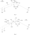
- the surgical stent delivery system 100 includes a main liner 111, a branch liner 112 and an operating handle 113 and is configured to load and deliver a surgical stent 200.
- the branch liner 112 is disposed on the main liner 111 and may project laterally outward from an outer circumference thereof.
- the operating handle 113 may be disposed at a proximal end of the main liner 111 and be in communication therewith.
- the operating handle 113 may be structured as a housing and manipulated by an operator to control the delivery, loading, positioning and deployment of the surgical stent 200, as well as any other operations related to the implantation of the surgical stent 200.
- the soft cover 230 may cover the main stent 210 and/or the branch stent 220.
- the vascular graft 240 may be configured to be sleeved over the main liner 111 as well as coupled and in communication with a proximal end of the main stent 210.
- the vascular graft 240 is preferably a coated vascular graft.
- the branch liner 112 is pivotably arranged on the main liner 111 so that the branch stent 220 disposed over the branch liner 112 can pivot with respect to the main stent 210 over the main liner 111 in synchronization with the pivoting of the branch liner 112.
- the main liner 111 may include a first portion 111a and a second portion 11 1b. Both of the first portion 111a and the second portion 11 1b are hollow and in communication with each other.
- the first portion 111a may be curved axially so as to better conform to the anatomy of the aortic arch.
- the second portion 111b may be disposed at a distal end of the main liner 111.
- the first portion 111a may be disposed at the proximal end of the main liner 111 and be in communication with the operating handle 113.
- the branch liner 112 may be pivotably arranged on the first portion 111a.
- the first portion 111a is configured to fit the aortic arch so as to simultaneously bring the branch stent 220 of the surgical stent 200 and the second portion 111b into fit with the left subclavian artery and the descending aorta, respectively. In this way, better positioning of the surgical stent 200 in the aorta can be achieved.
- the first and second portions 111a, 111b may either be joined together by riveting or integral with each other, and the present invention is not particularly limited in this regard.
- the surgical stent delivery system 100 may further include a pivoting adjustment member 114 provided on the operating handle 113 and be coupled to the branch liner 112 so as to drive the branch liner 112 to pivot with respect to the main liner 111.
- the branch liner 112 is pivotable to the left or right about a pivot axis, resulting in a change in an angle between the branch liner 112 and the main liner 111.
- the branch liner 112 in Fig. 4 has pivoted counterclockwise (i.e., proximally) by a first angle ⁇ 1.
- the branch liner 112 has shifted to the left (proximally) from the position X to the position Y.
- the branch liner 112 prior to the pivoting is shown as a dashed box.
- the branch liner 112 in Fig. 5 has pivoted clockwise (i.e., distally) by a second angle ⁇ 2. Specifically, the branch liner 112 has shifted to the right (distally) from the position X to the position Z. In Fig. 5 , the branch liner 112 prior to the pivoting is shown as a dashed box.
- the present invention is not limited to any particular value of the angle by which the branch liner 112 pivots clockwise or counterclockwise (proximally or distally), and it may be determined according to the actual applications.
- the pivot axis may be defined by a center axis of a rotating shaft.
- an aperture is arranged on the wall of the first portion 111a.
- the rotating shaft may be fixedly arranged on the wall of the first portion 111a around an aperture.
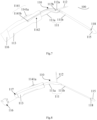
- the pivoting adjustment member 114 may include a slider assembly 1141 and a linkage assembly 1142.
- the slider assembly 1141 may include a slider 1141a and a base 1141b, which are connected to each other and disposed outside and inside the operating handle 113, respectively.
- the linkage assembly 1142 may consist of a first part received within the operating handle 113 and pivotably or fixedly coupled to the base 1141b and a second part received within the first portion 111a and pivotably coupled to the branch liner 112.
- the operating handle 113 is provided with a sliding slot and the slider 114a may be slidably arranged in the sliding slot.
- the branch liner 112 may be pivotably coupled to the rotating shaft, with the linkage assembly 1142 pivotably coupled to the branch liner 112 on one side of the rotating shaft (e.g., on the right side as shown in Fig. 6 ), so that when the linkage assembly 1142 moves under the driving of the slider assembly 1141, it causes the branch liner 112 to synchronously pivot about the rotating shaft.
- a first hole 112a and a second hole 112b may be arranged in the branch liner 112 with a spacing therebetween.
- the branch liner 112 is inserted over the rotating shaft with the aid of the first hole 112a so as to be pivotable about the rotating shaft and coupled to the linkage assembly 1142 with the aid of the second hole 112b so as to be pivotable with respect to the linkage assembly 1142.
- the branch liner 112 may be fixedly coupled to a connecting shaft.
- the first and second holes 112a, 112b that are spaced apart from each other are arranged on the connecting shaft.
- the other portion of the linkage assembly 1142 may define a protrusion projecting therefrom.
- the rotating shaft integral with the first portion 111a and the protrusion of the linkage assembly 1142 may be inserted into the first and second holes 112a, 112b, respectively, so that the branch liner 112 can pivot under the driving of the linkage assembly 1142.
- a third hole may be arranged in the base 1141b.
- a fourth hole may be arranged in the second part of the linkage assembly 1142 received within the first portion 111a.
- a pin may be inserted through both the third and fourth holes to pivotably couple the first part of the linkage assembly 1142 to the base 1141b.
- the slider 1141a may be pushed to proximal or distal ends of the surgical stent delivery system 100 so as to drive the linkage assembly 1142 to move in the same direction and hence the trailing end of the branch liner 112 to move in the same direct.
- the leading end of the branch liner 112 Since the trailing end of the branch liner 112 is received within the main liner 111, with the other end (i.e., the leading end) projecting out of the main liner 111, the leading end of the branch liner 112 will pivot toward the operating handle 113 (i.e., proximally) with the movement of the trailing end of the branch liner 112 toward a fixed tip 115 of the surgical stent delivery system 100 (i.e., distally). For example, when the slider 114a is pushed to the right side of Fig.
- the branch liner 112 will pivot toward the left side (i.e., toward the operating handle 113 of the system); and when the slider 1141a is pushed to the left side of Fig. 7 (i.e., toward the operating handle 113), the branch liner 112 will pivot toward the fixed tip 115 (i.e., to the right side).
- the pivoting adjustment member 114 may further include a limit structure (not shown).
- a limit structure (not shown).
- the branch liner 112 pivots to left or right until against the limit structure, the branch liner 112 stops pivoting; or when the linkage assembly 1142 moves toward the fixed tip 115 or the operating handle 113 until against the limit structure, the linkage assembly 1142 stops moving.
- the stent delivery system 100 may further include an external wire puller 116 and an internal wire puller 117 that are disposed at the proximal end of the operating handle 113.
- Each of the external wire puller 116 and the internal wire puller 117 is detachable to the operating handle 113.
- the external wire puller 116 When the external wire puller 116 is coupled to the operating handle 113, a part of the internal wire puller 117 may be received in the external wire puller 116 and the other part may be received in the operating handle 113.
- the external wire puller 116 may be detachably coupled to the operating handle 113 by a snap-on or threaded connection.
- the external wire puller 116 is configured to control the deployment of the main stent 210. Specifically, when the external wire puller 116 is pulled to the left of the surgical stent delivery system 100, for example, a binding thread to constrain arranged on the main stent 210 may be loosened under the effect of the external wire puller 116, thereby deploying the main stent 210 to a target site. Similarly, the internal wire puller 117 is configured to control the deployment of the branch stent 220.
- the fixed tip 115 may be disposed at a distal end of the second portion 111b.
- the fixed tip 115 is preferably selected as a tapered structure so that it can not only avoid cause damage to any vascular tissue but also facilitate the delivery due to streamlined surface of the taper.
- the fixed tip 115 may define a guide hole 118.
- a guide wire may be introduced into a true lumen of the diseased aorta at one end and into the guide hole 118 at the other end. The entire delivery system may be then advanced along the guide wire into the true lumen of the diseased aorta, followed by deployment of the surgical stent 200 therein.
- each of the operating handle 113, the external wire puller 116, the internal wire puller 117, the fixed tip 115, the slider 1141a, the branch liner 112 and the main liner 111 may be made of a biocompatible material, such as a polymer material.
- each of the operating handle 113, the external wire puller 116, the internal wire puller 117 and the fixed tip 115 may be made of one or more of PC (polycarbonate) and ABS (acrylonitrile-butadiene-styrene).
- Each of the slider 1141a, the branch liner 112 and the main liner 111 may be made of a material such as silicone or rubber.
- the surgical stent delivery system 100 may further include a pre-bent tube inserted into the main liner 111.
- the pre-bent tube may have better deformation performance than the main liner 111 and can help bend the main liner 111 to a curvature required by the target aorta in advance prior to the delivery and implantation of the surgical stent 200.
- the pre-bent tube may be configured to be inserted into the second portion 111b of the main liner 111 so as to bend the second portion 111b to a desired curvature for the target descending aorta in advance, thus changing the overall curvature of the main liner 111. This is helpful in adapting the surgical stent 200 to the actual three-dimensional vascular anatomy and improving its deployment effect.
- the pre-bent tube may have an outer diameter ranging from 1.0 mm to 1.8 mm, more preferably 1.0 mm, 1.2 mm, 1.5 mm or 1.8 mm.
- the diameter of the pre-bent tube is so chosen based on the present inventors' consideration that a greater diameter will increase the effort required to create the curvature of the pre-bent tube, while a smaller diameter will make the pre-bent tube less rigid and easily deformable, which is unfavorable to the delivery.
- the pre-bent tube is preferably made of stainless steel.
- the soft cover 230 may be configured to collaborate with the binding threads to constrain the surgical stent 200 so that the surgical stent 200 can be loaded in the surgical stent delivery system 100 and delivered into the patient's body, as shown in Fig. 9 .
- Concerning the soft cover 230 it may have another function. For example, during implantation of the surgical stent 200 wrapped by the soft cover 230, the surface smoothness of the surgical stent 200 may be increased, so that vascular damage may be avoided and the advancement and delivery of the surgical stent 200 may be facilitated.
- a process to deliver the surgical stent 200 will be described below with combined reference to Figs. 9 to 11 .
- a preoperative assessment may be performed to determine the curvatures of the aortic arch and the descending aorta.
- the second portion 111b may be then pre-bent based on the curvature of the descending aorta so that a reasonable matching curvature may be achieved.
- the slider 1141a on the operating handle 113 may be moved forth or back to tune the angle between the branch stent 220 and the main stent 210.
- the guide wire may be inserted into the true lumen of the diseased aorta at one end and the guide hole 118 of the fixed tip 115 at the other end.
- the surgical stent delivery system 100 loaded with the surgical stent 200 may be then delivered along the guide wire to the lesion site.
- the branch stent 220 may be positioned in the left subclavian artery, and the main stent 210 and the branch stent 220 may be then sequentially deployed by manipulating the external wire puller 116 and the internal wire puller 117, respectively, as shown in Fig. 10 .
Landscapes
- Health & Medical Sciences (AREA)
- Engineering & Computer Science (AREA)
- Biomedical Technology (AREA)
- Heart & Thoracic Surgery (AREA)
- Oral & Maxillofacial Surgery (AREA)
- Transplantation (AREA)
- Cardiology (AREA)
- Vascular Medicine (AREA)
- Life Sciences & Earth Sciences (AREA)
- Animal Behavior & Ethology (AREA)
- General Health & Medical Sciences (AREA)
- Public Health (AREA)
- Veterinary Medicine (AREA)
- Prostheses (AREA)
- Media Introduction/Drainage Providing Device (AREA)
Claims (8)
- Chirurgisches Stentsystem, umfassend einen chirurgischen Stent (200) und ein chirurgisches Stenteinführungssystem (100) zum Laden und Zuführen des chirurgischen Stents (200), wobei das chirurgische Stenteinführungssystem (100) einen Hauptliner (111), einen an dem Hauptliner (111) angeordneten Zweigliner (112), einen mit dem Hauptliner (111) in Verbindung stehenden Betätigungsgriff (113) und ein schwenkbares Einstellelement (114) umfasst, das auf dem Betätigungsgriff (113) vorgesehen und mit dem Zweigliner (112) gekoppelt ist, um den Zweigliner (112) in Bezug auf den Hauptliner (111) zum Drehen anzutreiben, wobei der Zweigliner (112) drehbar auf dem Hauptliner (111) angeordnet ist;wobei das schwenkbare Einstellelement (114) eine Schieberbaugruppe (1141) und eine Verbindungsbaugruppe (1142) umfasst, wobei die Schieberbaugruppe (1141) einen verschiebbar auf dem Betätigungsgriff (113) angeordneten Schieber (1141a) und eine mit dem Schieber (1141a) verbundene Basis (1141b) umfasst, wobei der Schieber (1141a) und die Basis (1141b) entsprechend außerhalb und innerhalb des Betätigungsgriffs (113) angeordnet sind;wobei ein erster Teil der Verbindungsbaugruppe (1142) drehbar oder fest mit der Basis (1141b) gekoppelt ist und ein zweiter Teil der Verbindungsbaugruppe (1142) drehbar mit dem Zweigliner (112) gekoppelt ist;wobei der chirurgische Stent (200) einen Hauptstent (210) und einen Zweigstent (220) umfasst, der auf dem Hauptstent (210) angeordnet ist und von einem Außenumfang des Hauptstents (210) vorsteht, wobei der Zweigstent (220) ausgebildet ist, über den Zweigliner (112) gehülst zu werden, wobei der Hauptstent (210) ausgebildet ist, über den Hauptliner (111) gehülst zu werden;wobei der chirurgische Stent (200) ferner ein Softcover (230) umfasst, das den Hauptstent (210) und/oder den Zweigstent (220) bedeckt;wobei der chirurgische Stent (200) ferner ein mit einem proximalen Ende des Hauptstents (210) gekoppeltes und in Verbindung stehendes Gefäßtransplantat (240) umfasst, wobei das Gefäßtransplantat (240) ausgebildet ist, über den Hauptliner (111) gehülst zu werden.
- Chirurgisches Stentsystem nach Anspruch 1, wobei der Hauptliner (111) einen ersten Abschnitt (111a) und einen zweiten Abschnitt (111b) umfasst, die miteinander in Verbindung stehen, wobei der Zweigliner (112) drehbar auf dem ersten Abschnitt (111a) angeordnet ist, wobei der Betätigungsgriff (113) mit dem ersten Abschnitt (111a) in Verbindung steht.
- Chirurgisches Stentsystem nach Anspruch 2, wobei der erste Teil der Verbindungsbaugruppe (1142) in dem Betätigungsgriff (113) aufgenommen ist, und wobei der zweite Teil der Verbindungsbaugruppe (1142) in dem ersten Abschnitt (111a) des Hauptliners (111) aufgenommen ist.
- Chirurgisches Stentsystem nach Anspruch 3, wobei eine Öffnung in einer Wand des ersten Abschnitts (111a) des Hauptliners (111) angeordnet ist, wobei eine Drehwelle fest an der Wand des ersten Abschnitts (111a) an der Öffnung angebracht ist, wobei ein Ende der Zweigliner (112) drehbar mit der Drehwelle verbunden ist, und wobei der zweite Teil der Verbindungsbaugruppe (1142) drehbar mit dem Ende der Zweigliner (112) auf einer Seite der Drehwelle verbunden ist, so dass der Zweigliner (112) unter Ansteuerung der Verbindungsbaugruppe (1142) um die Drehwelle drehbar ist.
- Chirurgisches Stentsystem nach Anspruch 4, wobei die Drehwelle einstückig mit dem ersten Abschnitt (111a) des Hauptliners (111) ausgebildet ist.
- Chirurgische Stentsystem nach Anspruch 4, wobei das Ende des Zweigliners (112) mit einer Verbindungswelle verbunden ist, in der ein erstes Loch (112a) und ein zweites Loch (112b), mit einem Abstand dazwischen, angeordnet sind; wobei die Verbindungsbaugruppe (1142) einen davon hervorstehenden Vorsprung aufweist; und wobei die Drehwelle beweglich in dem ersten Loch (112a) aufgenommen und der Vorsprung beweglich in dem zweiten Loch (112b) aufgenommen ist.
- Chirurgisches Stentsystem nach Anspruch 3, wobei der erste Abschnitt (111a) des Hauptliners (111) axial gekrümmt ist und der in dem ersten Abschnitt (111a) aufgenommene zweite Teil der Verbindungsbaugruppe (1142) axial gekrümmt ist.
- Chirurgisches Stentsystem nach Anspruch 2, ferner umfassend ein vorgebogenes Rohr, das ausgebildet ist, in den zweiten Abschnitt (111b) des Hauptliners (111) eingeführt zu werden, um eine Krümmung des zweiten Abschnitts (111b) durch das vorgebogene Rohr zu verändern.
Applications Claiming Priority (2)
| Application Number | Priority Date | Filing Date | Title |
|---|---|---|---|
| CN201611218484.2A CN106618822B (zh) | 2016-12-26 | 2016-12-26 | 术中支架输送系统以及术中支架系统 |
| PCT/CN2017/107327 WO2018121016A1 (zh) | 2016-12-26 | 2017-10-23 | 术中支架输送系统以及术中支架系统 |
Publications (3)
| Publication Number | Publication Date |
|---|---|
| EP3560460A1 EP3560460A1 (de) | 2019-10-30 |
| EP3560460A4 EP3560460A4 (de) | 2020-01-08 |
| EP3560460B1 true EP3560460B1 (de) | 2023-09-06 |
Family
ID=58827345
Family Applications (1)
| Application Number | Title | Priority Date | Filing Date |
|---|---|---|---|
| EP17886517.6A Active EP3560460B1 (de) | 2016-12-26 | 2017-10-23 | Intraoperatives stenteinführungssystem und intraoperatives stentsystem |
Country Status (5)
| Country | Link |
|---|---|
| EP (1) | EP3560460B1 (de) |
| JP (1) | JP6852189B2 (de) |
| CN (1) | CN106618822B (de) |
| BR (1) | BR112019013137B1 (de) |
| WO (1) | WO2018121016A1 (de) |
Families Citing this family (9)
| Publication number | Priority date | Publication date | Assignee | Title |
|---|---|---|---|---|
| CN106618822B (zh) * | 2016-12-26 | 2018-09-18 | 微创心脉医疗科技(上海)有限公司 | 术中支架输送系统以及术中支架系统 |
| CN107280808A (zh) * | 2017-07-20 | 2017-10-24 | 湖南埃普特医疗器械有限公司 | 输送系统及覆膜系统 |
| CN107802387B (zh) * | 2017-11-08 | 2019-10-22 | 有研医疗器械(北京)有限公司 | 一种术中支架输送系统及其使用方法 |
| CN109431666B (zh) * | 2018-12-28 | 2025-03-14 | 上海微创心脉医疗科技股份有限公司 | 术中支架输送装置和术中支架系统 |
| CN109893193B (zh) * | 2019-01-22 | 2024-01-02 | 中国医学科学院阜外医院 | 可阻血的象鼻支架 |
| CN115778461A (zh) * | 2019-12-18 | 2023-03-14 | 哈尔滨商业大学 | 一种含有滑动槽的动脉结扎拉力检测器 |
| CN113017952B (zh) * | 2021-05-26 | 2021-10-08 | 上海微创心脉医疗科技(集团)股份有限公司 | 分支鞘及输送系统 |
| CN113069258B (zh) * | 2021-06-07 | 2022-02-08 | 上海微创心脉医疗科技(集团)股份有限公司 | 一种输送器及医用装置 |
| CN118845296B (zh) * | 2024-09-27 | 2024-12-10 | 北京华脉泰科医疗器械股份有限公司 | 主动脉覆膜支架 |
Family Cites Families (24)
| Publication number | Priority date | Publication date | Assignee | Title |
|---|---|---|---|---|
| US5601591A (en) * | 1994-09-23 | 1997-02-11 | Vidamed, Inc. | Stent for use in prostatic urethra, apparatus and placement device for same and method |
| US6761734B2 (en) * | 2002-07-22 | 2004-07-13 | William S. Suhr | Segmented balloon catheter for stenting bifurcation lesions |
| JP2006507872A (ja) * | 2002-11-26 | 2006-03-09 | エンドロジックス、インク. | 移植片配備システム |
| EP1608293B1 (de) * | 2003-04-03 | 2015-06-03 | Cook Medical Technologies LLC | Einführsystem für einen verzweigten stent-graft |
| US7588596B2 (en) * | 2004-12-29 | 2009-09-15 | Scimed Life Systems, Inc. | Endoluminal prosthesis adapted to resist migration and method of deploying the same |
| US8287583B2 (en) * | 2005-01-10 | 2012-10-16 | Taheri Laduca Llc | Apparatus and method for deploying an implantable device within the body |
| CN1911188B (zh) * | 2005-08-09 | 2010-10-13 | 微创医疗器械(上海)有限公司 | 术中支架假体以及输送器 |
| US7678141B2 (en) * | 2006-04-18 | 2010-03-16 | Medtronic Vascular, Inc. | Stent graft having a flexible, articulable, and axially compressible branch graft |
| US8029558B2 (en) * | 2006-07-07 | 2011-10-04 | Abbott Cardiovascular Systems, Inc. | Stent and catheter assembly and method for treating bifurcations |
| US8454681B2 (en) * | 2006-09-13 | 2013-06-04 | Boston Scientific Scimed, Inc. | Bifurcation delivery systems and methods |
| US20080114444A1 (en) * | 2006-11-09 | 2008-05-15 | Chun Ho Yu | Modular stent graft and delivery system |
| US20090099648A1 (en) * | 2006-11-09 | 2009-04-16 | Chun Ho Yu | Modular stent graft and delivery system |
| CN201046170Y (zh) * | 2007-02-28 | 2008-04-16 | 许尚栋 | 侧支型覆膜支架 |
| US9034030B2 (en) * | 2007-03-12 | 2015-05-19 | Cook Medical Technologies Llc | Helical arm tie down |
| CN101897629B (zh) * | 2009-05-26 | 2013-08-07 | 上海微创医疗器械(集团)有限公司 | 分支型覆膜支架输送系统及其输送方法 |
| US20120209375A1 (en) * | 2011-02-11 | 2012-08-16 | Gilbert Madrid | Stability device for use with percutaneous delivery systems |
| US8574283B1 (en) * | 2011-08-30 | 2013-11-05 | Suraj Govind Kamat | Deployment of stents within bifurcated vessels |
| CN102415924B (zh) * | 2011-09-16 | 2014-11-26 | 上海微创医疗器械(集团)有限公司 | 一种分支鞘及应用该分支鞘的血管支架输送释放装置 |
| CN202776649U (zh) * | 2012-05-07 | 2013-03-13 | 李卫校 | 连体式大血管分支支架推送器 |
| CN105213067B (zh) * | 2014-06-25 | 2017-05-24 | 北京奇伦天佑创业投资有限公司 | 覆膜和支架分别植入的植入系统 |
| US9956101B2 (en) * | 2014-12-04 | 2018-05-01 | Trivascular, Inc. | Internal iliac preservation devices and methods |
| WO2016123676A1 (en) * | 2015-02-05 | 2016-08-11 | State Of The Heart Innovations Pty Ltd | Aortic stent graft, delivery system and method |
| CN104873305B (zh) * | 2015-05-29 | 2017-06-06 | 有研亿金新材料有限公司 | 术中分支按需阻断式支架型人工血管系统及使用方法 |
| CN106618822B (zh) * | 2016-12-26 | 2018-09-18 | 微创心脉医疗科技(上海)有限公司 | 术中支架输送系统以及术中支架系统 |
-
2016
- 2016-12-26 CN CN201611218484.2A patent/CN106618822B/zh active Active
-
2017
- 2017-10-23 EP EP17886517.6A patent/EP3560460B1/de active Active
- 2017-10-23 JP JP2019555532A patent/JP6852189B2/ja active Active
- 2017-10-23 BR BR112019013137-0A patent/BR112019013137B1/pt active IP Right Grant
- 2017-10-23 WO PCT/CN2017/107327 patent/WO2018121016A1/zh not_active Ceased
Also Published As
| Publication number | Publication date |
|---|---|
| EP3560460A1 (de) | 2019-10-30 |
| WO2018121016A1 (zh) | 2018-07-05 |
| JP2020503160A (ja) | 2020-01-30 |
| CN106618822A (zh) | 2017-05-10 |
| CN106618822B (zh) | 2018-09-18 |
| BR112019013137B1 (pt) | 2023-12-26 |
| JP6852189B2 (ja) | 2021-03-31 |
| EP3560460A4 (de) | 2020-01-08 |
| BR112019013137A2 (pt) | 2019-12-24 |
Similar Documents
| Publication | Publication Date | Title |
|---|---|---|
| EP3560460B1 (de) | Intraoperatives stenteinführungssystem und intraoperatives stentsystem | |
| US12433736B2 (en) | Thoracic aorta stent graft | |
| CN101961269B (zh) | 用于输送人造瓣膜置换装置的输送装置 | |
| JP7112393B2 (ja) | シースが収縮されたステントグラフト送達システムおよび使用方法 | |
| CN101415377B (zh) | 支架植入物近端自定心输送系统和方法 | |
| CN101953724B (zh) | 用于装载人造瓣膜置换装置的支架固定头 | |
| JP5665149B2 (ja) | 経心尖搬送装置及び使用方法 | |
| US20190216623A1 (en) | Apparatus and method of placement of a graft or graft system | |
| JP4904361B2 (ja) | 人工心臓弁の植え込み及び固定のための装置 | |
| JP7144616B2 (ja) | インプラントを血管内に供給、設置する装置 | |
| CN101953729B (zh) | 一种使用安全的人造瓣膜置换装置及支架 | |
| CN112118807A (zh) | 用于多个血管的模块化支架装置和方法 | |
| US20250345167A1 (en) | Stent graft and use method therefor | |
| CN1911188B (zh) | 术中支架假体以及输送器 | |
| CN101953725A (zh) | 人造瓣膜置换装置及支架 | |
| EP3946152B1 (de) | Modulare stentanordnung für supraaortalen zugang | |
| CN112842619A (zh) | 弓部覆膜支架和覆膜支架输送器 | |
| CN214857826U (zh) | 弓部覆膜支架和覆膜支架输送器 | |
| US7553323B1 (en) | Steerable endovascular graft delivery system | |
| US12144753B2 (en) | Stent graft delivery system including a tapered tip offset through-channel aligning with a first guidewire lumen | |
| CN117481867A (zh) | 自适应式跨弓胸主动脉覆膜支架及其系统 | |
| CN115243647A (zh) | 分支支架移植物递送系统 | |
| CN223041679U (zh) | 血管支架以及支架系统 |
Legal Events
| Date | Code | Title | Description |
|---|---|---|---|
| STAA | Information on the status of an ep patent application or granted ep patent |
Free format text: STATUS: THE INTERNATIONAL PUBLICATION HAS BEEN MADE |
|
| PUAI | Public reference made under article 153(3) epc to a published international application that has entered the european phase |
Free format text: ORIGINAL CODE: 0009012 |
|
| STAA | Information on the status of an ep patent application or granted ep patent |
Free format text: STATUS: REQUEST FOR EXAMINATION WAS MADE |
|
| 17P | Request for examination filed |
Effective date: 20190701 |
|
| AK | Designated contracting states |
Kind code of ref document: A1 Designated state(s): AL AT BE BG CH CY CZ DE DK EE ES FI FR GB GR HR HU IE IS IT LI LT LU LV MC MK MT NL NO PL PT RO RS SE SI SK SM TR |
|
| AX | Request for extension of the european patent |
Extension state: BA ME |
|
| A4 | Supplementary search report drawn up and despatched |
Effective date: 20191211 |
|
| RIC1 | Information provided on ipc code assigned before grant |
Ipc: A61F 2/966 20130101ALI20191205BHEP Ipc: A61F 2/82 20130101ALI20191205BHEP Ipc: A61F 2/06 20130101ALI20191205BHEP Ipc: A61F 2/97 20130101ALI20191205BHEP Ipc: A61F 2/95 20130101AFI20191205BHEP Ipc: A61F 2/07 20130101ALI20191205BHEP Ipc: A61F 2/856 20130101ALI20191205BHEP Ipc: A61F 2/954 20130101ALI20191205BHEP |
|
| DAV | Request for validation of the european patent (deleted) | ||
| DAX | Request for extension of the european patent (deleted) | ||
| STAA | Information on the status of an ep patent application or granted ep patent |
Free format text: STATUS: EXAMINATION IS IN PROGRESS |
|
| 17Q | First examination report despatched |
Effective date: 20220328 |
|
| REG | Reference to a national code |
Ref country code: DE Ref legal event code: R079 Free format text: PREVIOUS MAIN CLASS: A61F0002950000 Ipc: A61F0002954000 Ref country code: DE Ref legal event code: R079 Ref document number: 602017073978 Country of ref document: DE Free format text: PREVIOUS MAIN CLASS: A61F0002950000 Ipc: A61F0002954000 |
|
| GRAP | Despatch of communication of intention to grant a patent |
Free format text: ORIGINAL CODE: EPIDOSNIGR1 |
|
| STAA | Information on the status of an ep patent application or granted ep patent |
Free format text: STATUS: GRANT OF PATENT IS INTENDED |
|
| RIC1 | Information provided on ipc code assigned before grant |
Ipc: A61F 2/07 20130101ALN20230203BHEP Ipc: A61F 2/954 20130101AFI20230203BHEP |
|
| INTG | Intention to grant announced |
Effective date: 20230302 |
|
| GRAS | Grant fee paid |
Free format text: ORIGINAL CODE: EPIDOSNIGR3 |
|
| GRAA | (expected) grant |
Free format text: ORIGINAL CODE: 0009210 |
|
| STAA | Information on the status of an ep patent application or granted ep patent |
Free format text: STATUS: THE PATENT HAS BEEN GRANTED |
|
| RAP3 | Party data changed (applicant data changed or rights of an application transferred) |
Owner name: SHANGHAI MICROPORT ENDOVASCULAR MEDTECH (GROUP) CO., LTD. |
|
| AK | Designated contracting states |
Kind code of ref document: B1 Designated state(s): AL AT BE BG CH CY CZ DE DK EE ES FI FR GB GR HR HU IE IS IT LI LT LU LV MC MK MT NL NO PL PT RO RS SE SI SK SM TR |
|
| REG | Reference to a national code |
Ref country code: GB Ref legal event code: FG4D |
|
| REG | Reference to a national code |
Ref country code: CH Ref legal event code: EP |
|
| REG | Reference to a national code |
Ref country code: DE Ref legal event code: R096 Ref document number: 602017073978 Country of ref document: DE |
|
| REG | Reference to a national code |
Ref country code: IE Ref legal event code: FG4D |
|
| REG | Reference to a national code |
Ref country code: LT Ref legal event code: MG9D |
|
| P01 | Opt-out of the competence of the unified patent court (upc) registered |
Effective date: 20231128 |
|
| REG | Reference to a national code |
Ref country code: NL Ref legal event code: MP Effective date: 20230906 |
|
| PG25 | Lapsed in a contracting state [announced via postgrant information from national office to epo] |
Ref country code: GR Free format text: LAPSE BECAUSE OF FAILURE TO SUBMIT A TRANSLATION OF THE DESCRIPTION OR TO PAY THE FEE WITHIN THE PRESCRIBED TIME-LIMIT Effective date: 20231207 |
|
| PG25 | Lapsed in a contracting state [announced via postgrant information from national office to epo] |
Ref country code: SE Free format text: LAPSE BECAUSE OF FAILURE TO SUBMIT A TRANSLATION OF THE DESCRIPTION OR TO PAY THE FEE WITHIN THE PRESCRIBED TIME-LIMIT Effective date: 20230906 Ref country code: RS Free format text: LAPSE BECAUSE OF FAILURE TO SUBMIT A TRANSLATION OF THE DESCRIPTION OR TO PAY THE FEE WITHIN THE PRESCRIBED TIME-LIMIT Effective date: 20230906 Ref country code: NO Free format text: LAPSE BECAUSE OF FAILURE TO SUBMIT A TRANSLATION OF THE DESCRIPTION OR TO PAY THE FEE WITHIN THE PRESCRIBED TIME-LIMIT Effective date: 20231206 Ref country code: LV Free format text: LAPSE BECAUSE OF FAILURE TO SUBMIT A TRANSLATION OF THE DESCRIPTION OR TO PAY THE FEE WITHIN THE PRESCRIBED TIME-LIMIT Effective date: 20230906 Ref country code: LT Free format text: LAPSE BECAUSE OF FAILURE TO SUBMIT A TRANSLATION OF THE DESCRIPTION OR TO PAY THE FEE WITHIN THE PRESCRIBED TIME-LIMIT Effective date: 20230906 Ref country code: HR Free format text: LAPSE BECAUSE OF FAILURE TO SUBMIT A TRANSLATION OF THE DESCRIPTION OR TO PAY THE FEE WITHIN THE PRESCRIBED TIME-LIMIT Effective date: 20230906 Ref country code: GR Free format text: LAPSE BECAUSE OF FAILURE TO SUBMIT A TRANSLATION OF THE DESCRIPTION OR TO PAY THE FEE WITHIN THE PRESCRIBED TIME-LIMIT Effective date: 20231207 Ref country code: FI Free format text: LAPSE BECAUSE OF FAILURE TO SUBMIT A TRANSLATION OF THE DESCRIPTION OR TO PAY THE FEE WITHIN THE PRESCRIBED TIME-LIMIT Effective date: 20230906 |
|
| REG | Reference to a national code |
Ref country code: AT Ref legal event code: MK05 Ref document number: 1607520 Country of ref document: AT Kind code of ref document: T Effective date: 20230906 |
|
| PG25 | Lapsed in a contracting state [announced via postgrant information from national office to epo] |
Ref country code: NL Free format text: LAPSE BECAUSE OF FAILURE TO SUBMIT A TRANSLATION OF THE DESCRIPTION OR TO PAY THE FEE WITHIN THE PRESCRIBED TIME-LIMIT Effective date: 20230906 |
|
| PG25 | Lapsed in a contracting state [announced via postgrant information from national office to epo] |
Ref country code: IS Free format text: LAPSE BECAUSE OF FAILURE TO SUBMIT A TRANSLATION OF THE DESCRIPTION OR TO PAY THE FEE WITHIN THE PRESCRIBED TIME-LIMIT Effective date: 20240106 |
|
| PG25 | Lapsed in a contracting state [announced via postgrant information from national office to epo] |
Ref country code: AT Free format text: LAPSE BECAUSE OF FAILURE TO SUBMIT A TRANSLATION OF THE DESCRIPTION OR TO PAY THE FEE WITHIN THE PRESCRIBED TIME-LIMIT Effective date: 20230906 |
|
| PG25 | Lapsed in a contracting state [announced via postgrant information from national office to epo] |
Ref country code: ES Free format text: LAPSE BECAUSE OF FAILURE TO SUBMIT A TRANSLATION OF THE DESCRIPTION OR TO PAY THE FEE WITHIN THE PRESCRIBED TIME-LIMIT Effective date: 20230906 |
|
| PG25 | Lapsed in a contracting state [announced via postgrant information from national office to epo] |
Ref country code: SM Free format text: LAPSE BECAUSE OF FAILURE TO SUBMIT A TRANSLATION OF THE DESCRIPTION OR TO PAY THE FEE WITHIN THE PRESCRIBED TIME-LIMIT Effective date: 20230906 Ref country code: RO Free format text: LAPSE BECAUSE OF FAILURE TO SUBMIT A TRANSLATION OF THE DESCRIPTION OR TO PAY THE FEE WITHIN THE PRESCRIBED TIME-LIMIT Effective date: 20230906 Ref country code: IS Free format text: LAPSE BECAUSE OF FAILURE TO SUBMIT A TRANSLATION OF THE DESCRIPTION OR TO PAY THE FEE WITHIN THE PRESCRIBED TIME-LIMIT Effective date: 20240106 Ref country code: ES Free format text: LAPSE BECAUSE OF FAILURE TO SUBMIT A TRANSLATION OF THE DESCRIPTION OR TO PAY THE FEE WITHIN THE PRESCRIBED TIME-LIMIT Effective date: 20230906 Ref country code: EE Free format text: LAPSE BECAUSE OF FAILURE TO SUBMIT A TRANSLATION OF THE DESCRIPTION OR TO PAY THE FEE WITHIN THE PRESCRIBED TIME-LIMIT Effective date: 20230906 Ref country code: CZ Free format text: LAPSE BECAUSE OF FAILURE TO SUBMIT A TRANSLATION OF THE DESCRIPTION OR TO PAY THE FEE WITHIN THE PRESCRIBED TIME-LIMIT Effective date: 20230906 Ref country code: AT Free format text: LAPSE BECAUSE OF FAILURE TO SUBMIT A TRANSLATION OF THE DESCRIPTION OR TO PAY THE FEE WITHIN THE PRESCRIBED TIME-LIMIT Effective date: 20230906 Ref country code: PT Free format text: LAPSE BECAUSE OF FAILURE TO SUBMIT A TRANSLATION OF THE DESCRIPTION OR TO PAY THE FEE WITHIN THE PRESCRIBED TIME-LIMIT Effective date: 20240108 Ref country code: SK Free format text: LAPSE BECAUSE OF FAILURE TO SUBMIT A TRANSLATION OF THE DESCRIPTION OR TO PAY THE FEE WITHIN THE PRESCRIBED TIME-LIMIT Effective date: 20230906 |
|
| PG25 | Lapsed in a contracting state [announced via postgrant information from national office to epo] |
Ref country code: PL Free format text: LAPSE BECAUSE OF FAILURE TO SUBMIT A TRANSLATION OF THE DESCRIPTION OR TO PAY THE FEE WITHIN THE PRESCRIBED TIME-LIMIT Effective date: 20230906 Ref country code: IT Free format text: LAPSE BECAUSE OF FAILURE TO SUBMIT A TRANSLATION OF THE DESCRIPTION OR TO PAY THE FEE WITHIN THE PRESCRIBED TIME-LIMIT Effective date: 20230906 |
|
| REG | Reference to a national code |
Ref country code: CH Ref legal event code: PL |
|
| REG | Reference to a national code |
Ref country code: DE Ref legal event code: R097 Ref document number: 602017073978 Country of ref document: DE |
|
| REG | Reference to a national code |
Ref country code: BE Ref legal event code: MM Effective date: 20231031 |
|
| PG25 | Lapsed in a contracting state [announced via postgrant information from national office to epo] |
Ref country code: LU Free format text: LAPSE BECAUSE OF NON-PAYMENT OF DUE FEES Effective date: 20231023 |
|
| PG25 | Lapsed in a contracting state [announced via postgrant information from national office to epo] |
Ref country code: LU Free format text: LAPSE BECAUSE OF NON-PAYMENT OF DUE FEES Effective date: 20231023 |
|
| PG25 | Lapsed in a contracting state [announced via postgrant information from national office to epo] |
Ref country code: MC Free format text: LAPSE BECAUSE OF FAILURE TO SUBMIT A TRANSLATION OF THE DESCRIPTION OR TO PAY THE FEE WITHIN THE PRESCRIBED TIME-LIMIT Effective date: 20230906 |
|
| PG25 | Lapsed in a contracting state [announced via postgrant information from national office to epo] |
Ref country code: DK Free format text: LAPSE BECAUSE OF FAILURE TO SUBMIT A TRANSLATION OF THE DESCRIPTION OR TO PAY THE FEE WITHIN THE PRESCRIBED TIME-LIMIT Effective date: 20230906 |
|
| PLBE | No opposition filed within time limit |
Free format text: ORIGINAL CODE: 0009261 |
|
| STAA | Information on the status of an ep patent application or granted ep patent |
Free format text: STATUS: NO OPPOSITION FILED WITHIN TIME LIMIT |
|
| PG25 | Lapsed in a contracting state [announced via postgrant information from national office to epo] |
Ref country code: CH Free format text: LAPSE BECAUSE OF NON-PAYMENT OF DUE FEES Effective date: 20231031 |
|
| PG25 | Lapsed in a contracting state [announced via postgrant information from national office to epo] |
Ref country code: MC Free format text: LAPSE BECAUSE OF FAILURE TO SUBMIT A TRANSLATION OF THE DESCRIPTION OR TO PAY THE FEE WITHIN THE PRESCRIBED TIME-LIMIT Effective date: 20230906 Ref country code: DK Free format text: LAPSE BECAUSE OF FAILURE TO SUBMIT A TRANSLATION OF THE DESCRIPTION OR TO PAY THE FEE WITHIN THE PRESCRIBED TIME-LIMIT Effective date: 20230906 Ref country code: CH Free format text: LAPSE BECAUSE OF NON-PAYMENT OF DUE FEES Effective date: 20231031 Ref country code: SI Free format text: LAPSE BECAUSE OF FAILURE TO SUBMIT A TRANSLATION OF THE DESCRIPTION OR TO PAY THE FEE WITHIN THE PRESCRIBED TIME-LIMIT Effective date: 20230906 |
|
| 26N | No opposition filed |
Effective date: 20240607 |
|
| GBPC | Gb: european patent ceased through non-payment of renewal fee |
Effective date: 20231206 |
|
| PG25 | Lapsed in a contracting state [announced via postgrant information from national office to epo] |
Ref country code: BE Free format text: LAPSE BECAUSE OF NON-PAYMENT OF DUE FEES Effective date: 20231031 |
|
| PG25 | Lapsed in a contracting state [announced via postgrant information from national office to epo] |
Ref country code: IE Free format text: LAPSE BECAUSE OF NON-PAYMENT OF DUE FEES Effective date: 20231023 |
|
| PG25 | Lapsed in a contracting state [announced via postgrant information from national office to epo] |
Ref country code: GB Free format text: LAPSE BECAUSE OF NON-PAYMENT OF DUE FEES Effective date: 20231206 |
|
| PG25 | Lapsed in a contracting state [announced via postgrant information from national office to epo] |
Ref country code: FR Free format text: LAPSE BECAUSE OF NON-PAYMENT OF DUE FEES Effective date: 20231106 |
|
| PG25 | Lapsed in a contracting state [announced via postgrant information from national office to epo] |
Ref country code: IE Free format text: LAPSE BECAUSE OF NON-PAYMENT OF DUE FEES Effective date: 20231023 Ref country code: GB Free format text: LAPSE BECAUSE OF NON-PAYMENT OF DUE FEES Effective date: 20231206 Ref country code: FR Free format text: LAPSE BECAUSE OF NON-PAYMENT OF DUE FEES Effective date: 20231106 |
|
| PG25 | Lapsed in a contracting state [announced via postgrant information from national office to epo] |
Ref country code: BG Free format text: LAPSE BECAUSE OF FAILURE TO SUBMIT A TRANSLATION OF THE DESCRIPTION OR TO PAY THE FEE WITHIN THE PRESCRIBED TIME-LIMIT Effective date: 20230906 |
|
| PG25 | Lapsed in a contracting state [announced via postgrant information from national office to epo] |
Ref country code: BG Free format text: LAPSE BECAUSE OF FAILURE TO SUBMIT A TRANSLATION OF THE DESCRIPTION OR TO PAY THE FEE WITHIN THE PRESCRIBED TIME-LIMIT Effective date: 20230906 |
|
| PG25 | Lapsed in a contracting state [announced via postgrant information from national office to epo] |
Ref country code: CY Free format text: LAPSE BECAUSE OF FAILURE TO SUBMIT A TRANSLATION OF THE DESCRIPTION OR TO PAY THE FEE WITHIN THE PRESCRIBED TIME-LIMIT; INVALID AB INITIO Effective date: 20171023 |
|
| PG25 | Lapsed in a contracting state [announced via postgrant information from national office to epo] |
Ref country code: HU Free format text: LAPSE BECAUSE OF FAILURE TO SUBMIT A TRANSLATION OF THE DESCRIPTION OR TO PAY THE FEE WITHIN THE PRESCRIBED TIME-LIMIT; INVALID AB INITIO Effective date: 20171023 |
|
| PG25 | Lapsed in a contracting state [announced via postgrant information from national office to epo] |
Ref country code: TR Free format text: LAPSE BECAUSE OF FAILURE TO SUBMIT A TRANSLATION OF THE DESCRIPTION OR TO PAY THE FEE WITHIN THE PRESCRIBED TIME-LIMIT Effective date: 20230906 |
|
| PGFP | Annual fee paid to national office [announced via postgrant information from national office to epo] |
Ref country code: DE Payment date: 20251021 Year of fee payment: 9 |