EP3560471B1 - Incubateur - Google Patents
Incubateur Download PDFInfo
- Publication number
- EP3560471B1 EP3560471B1 EP19175087.6A EP19175087A EP3560471B1 EP 3560471 B1 EP3560471 B1 EP 3560471B1 EP 19175087 A EP19175087 A EP 19175087A EP 3560471 B1 EP3560471 B1 EP 3560471B1
- Authority
- EP
- European Patent Office
- Prior art keywords
- wall section
- incubator
- wall
- infant
- state
- Prior art date
- Legal status (The legal status is an assumption and is not a legal conclusion. Google has not performed a legal analysis and makes no representation as to the accuracy of the status listed.)
- Active
Links
Images


Classifications
-
- A—HUMAN NECESSITIES
- A61—MEDICAL OR VETERINARY SCIENCE; HYGIENE
- A61G—TRANSPORT, PERSONAL CONVEYANCES, OR ACCOMMODATION SPECIALLY ADAPTED FOR PATIENTS OR DISABLED PERSONS; OPERATING TABLES OR CHAIRS; CHAIRS FOR DENTISTRY; FUNERAL DEVICES
- A61G11/00—Baby-incubators; Couveuses
-
- A—HUMAN NECESSITIES
- A61—MEDICAL OR VETERINARY SCIENCE; HYGIENE
- A61G—TRANSPORT, PERSONAL CONVEYANCES, OR ACCOMMODATION SPECIALLY ADAPTED FOR PATIENTS OR DISABLED PERSONS; OPERATING TABLES OR CHAIRS; CHAIRS FOR DENTISTRY; FUNERAL DEVICES
- A61G11/00—Baby-incubators; Couveuses
- A61G11/005—Baby-incubators; Couveuses with movable walls, e.g. for accessing the inside, removable walls
- A61G11/006—Baby-incubators; Couveuses with movable walls, e.g. for accessing the inside, removable walls by pivoting
-
- A—HUMAN NECESSITIES
- A61—MEDICAL OR VETERINARY SCIENCE; HYGIENE
- A61G—TRANSPORT, PERSONAL CONVEYANCES, OR ACCOMMODATION SPECIALLY ADAPTED FOR PATIENTS OR DISABLED PERSONS; OPERATING TABLES OR CHAIRS; CHAIRS FOR DENTISTRY; FUNERAL DEVICES
- A61G11/00—Baby-incubators; Couveuses
- A61G11/005—Baby-incubators; Couveuses with movable walls, e.g. for accessing the inside, removable walls
-
- A—HUMAN NECESSITIES
- A61—MEDICAL OR VETERINARY SCIENCE; HYGIENE
- A61G—TRANSPORT, PERSONAL CONVEYANCES, OR ACCOMMODATION SPECIALLY ADAPTED FOR PATIENTS OR DISABLED PERSONS; OPERATING TABLES OR CHAIRS; CHAIRS FOR DENTISTRY; FUNERAL DEVICES
- A61G2203/00—General characteristics of devices
- A61G2203/70—General characteristics of devices with special adaptations, e.g. for safety or comfort
-
- A—HUMAN NECESSITIES
- A61—MEDICAL OR VETERINARY SCIENCE; HYGIENE
- A61G—TRANSPORT, PERSONAL CONVEYANCES, OR ACCOMMODATION SPECIALLY ADAPTED FOR PATIENTS OR DISABLED PERSONS; OPERATING TABLES OR CHAIRS; CHAIRS FOR DENTISTRY; FUNERAL DEVICES
- A61G2203/00—General characteristics of devices
- A61G2203/70—General characteristics of devices with special adaptations, e.g. for safety or comfort
- A61G2203/78—General characteristics of devices with special adaptations, e.g. for safety or comfort for clamping
Definitions
- Preferred embodiments relate to an incubator including a mattress tray that an infant can be laid on, and plural baby guards capable of surrounding the vicinity of an outer periphery of the mattress tray, wherein at least one baby guard from out of the plural baby guards includes a grommet.
- Incubators are already known, such as that described in Japanese Patent Application Publication ( JP-A) No. 2012-223320 (referred to below as “the Patent Document”).
- the incubator described in the Patent Document a flat container shaped bed base is installed on an incubator base.
- the incubator stand is respectively installed with the following so as to form a substantially rectangular shape overall in plan view: a fixed wall section that generally configures a wall section on a head side of an infant (a fixed baby guard); a leg side movable wall section that generally configures a wall section on a leg side of the infant (a movable baby guard); a left side movable wall section that generally configures a wall section on a left side of the infant (a movable baby guard); and a right side movable wall section that generally configures a wall section on a right side of the infant (a movable baby guard).
- a substantially cuboid shaped infant accommodation space open on an upper face is configured by the mattress tray, or in other words by a mattress on the mattress tray, and by the single fixed wall section and the three movable wall sections which may each be substantially rectangular shaped and may be substantially transparent.
- the three movable wall sections and the single fixed wall section are each configured overall from a substantially transparent plastic sheet.
- the three movable wall sections are swingable to-and-fro between an upstanding state substantially upward (referred to below as “the upstanding state”) and a hanging state substantially downward (referred to below as “the hanging state”), by swinging about swing support shafts that are installed on left and right sides, or front and rear sides, in the vicinity of lower edges in the upstanding state of the three movable wall sections.
- the fixed wall section is fixed by being firmly attached to the incubator stand.
- a grommet member is attached to the fixed wall section.
- the incubator described in the closest prior art document US 6,234,954 comprises movable walls swingable around swing support shafts to achieve the upstanding and the hanging state of the walls.
- the doctor or nurse or the like when a doctor or nurse or the like is performing some kind of treatment or the like in the proximity of the head of the infant, due to the presence of an ancillary equipment support column in the vicinity of the fixed wall section generally configuring a wall section on the head side of the infant, the doctor or nurse or the like needs to perform treatment in the proximity of the head of the infant from the vicinity of the support column.
- the doctor or nurse or the like might conceivably perform treatment in the proximity of the head of the infant by switching over the head side of the infant and the leg side of the infant.
- an object of preferred embodiments is to provide an incubator that effectively solves the problem described above with the incubator of the Patent Document, using a comparatively simple configuration.
- An incubator of a first aspect of the disclosure includes a mattress tray configured to accommodate an infant laid thereon, and plural baby guards configured to surround a vicinity of an outer periphery of the mattress tray.
- a first baby guard f of the plural baby guards includes a grommet, and the first baby guard is detachably attached to a first attachment location installed at a vicinity of the outer periphery of the mattress tray.
- a second baby guard of the plural baby guards is detachably attached to a second attachment location installed at a vicinity of the outer periphery of the mattress tray. The first baby guard is detachable from the first attachment location and attachable to the second attachment location, and the second baby guard is detachable from the second attachment location and attachable to the first attachment location.
- the first baby guard including the grommet and the second baby guard that does not include a grommet can be interchanged with each other, thereby enabling a doctor or nurse or the like to attach the first baby guard to a convenient location.
- the breathing tubes or the like might be twisted or kinked by the infant's own body movements and the like.
- the at least one baby guard out of the first and second baby guards can be replaced with a spare baby guard as required.
- the first baby guard includes the grommet and the second baby guard does not include a grommet, thereby enabling plural baby guards to be provided at a comparatively low cost compared to cases in which both the first baby guard and the second baby guard include grommets.
- the plural baby guards include a front side baby guard formed by the second baby guard, a rear side baby guard formed by the first baby guard, and a left side baby guard and a right side baby guard.
- a front side baby guard formed by the second baby guard a rear side baby guard formed by the first baby guard
- a left side baby guard and a right side baby guard a front side baby guard formed by the second baby guard
- a rear side baby guard formed by the first baby guard a left side baby guard and a right side baby guard.
- an infant accommodation space having a substantially rectangular shape in plan view is configured by the plural baby guards.
- the incubator is an open incubator. Since the incubator is an open incubator, an incubator with a simple structure and simple handling can be provided.
- An open incubator 11, as illustrated in Fig. 1 includes a trolley 14, to which wheels 12 and a main pillar 13 are respectively attached. More specifically, the wheels 12 are attached below four corners of the trolley 14, and the main pillar 13 is attached above the trolley 14.
- An incubator base 15 is then installed above the main pillar 13.
- a flat container shaped mattress tray 16 is installed, as illustrated in Fig. 1 , Fig. 2 , Fig. 4 , etc., onto the incubator base 15.
- a mattress 21 can be laid on the mattress tray 16 to enable an infant, such as a newborn baby, to be laid thereon.
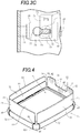
- the mattress tray 16 that has been installed by being attached and fixed onto the incubator base 15 is respectively installed with the following, as illustrated in Fig. 1 and Fig. 2 , so as to form a substantially rectangular shape overall in plan view: an outer wall section (an outer baby guard) 23 normally generally configuring an outer wall section on a head side of an infant, or the rear side, adjacent to an ancillary equipment support column 22 installed to the main pillar 13; an outer wall section (an outer baby guard) 24 normally generally configuring an outer wall section on a leg side of an infant, or the front side; an outer wall section (an outer baby guard) 25 normally generally configuring an outer wall section on a left side of an infant; and an outer wall section (an outer baby guard) 26 normally generally configuring an outer wall section on a right side of an infant.
- an outer wall section (an outer baby guard) 23 normally generally configuring an outer wall section on a head side of an infant, or the rear side, adjacent to an ancillary equipment support column 22 installed to the main pillar 13
- a substantially cuboid shaped infant accommodation space 27 open an upper face is configured by the mattress tray 16 (in other words, the mattress 21) and the outer wall sections 23 to 26 that respectively may be substantially rectangular shaped, and may be substantially transparent.
- the left side outer wall section 25 and the right side outer wall section 26 may have substantially the same dimensions as each other.
- the outer wall section 23 and the outer wall section 24, which have lengths in their respective length directions (in other words, horizontal directions) that are slightly shorter than those of the outer wall sections 25, 26, may have substantially the same dimensions as each other, except for a cutout shaped indentation 31 that is provided at the outer wall section 23 so as to extend from a substantially central portion of an upper edge of the outer wall section 23 to partway toward the lower edge thereof.
- the outer wall sections 23 to 26 may be respectively configured from sheets of plastic, such as polycarbonate resin or acrylic resin, which are substantially transparent overall.
- Each of the outer wall sections 24 to 26 is swingable to-and-fro between a substantially upstanding state (referred to below as “the upstanding state”) as illustrated in Fig. 1 and Fig. 2 , and a hanging state substantially downward illustrated in Fig. 6 (referred to below as “the hanging state”; however, in Fig. 6 , the outer wall section 26 is illustrated in the upstanding state), by swinging about swing support shafts 30 of swing support shaft members 29 arranged on the left and right sides, or the front and rear sides, in the vicinity of the lower edges of the outer wall sections 24 to 26 in the upstanding state illustrated in Fig 1 .
- the outer wall section 23 is also, in substantially the same manner as the outer wall section 24, axially supported by swing support shafts (not illustrated in the drawings) on the left and right sides.
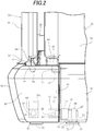
- Each of the swing support shafts 30 illustrated in Fig. 2 and Fig. 3A to Fig. 3C can be shifted out from an engaged state with an attachment member 46 as illustrated in Fig. 2 and Fig. 3A , through an intermediate state as illustrated in Fig. 3B , to a non-engaged state with the attachment member 46 as illustrated in Fig. 3C , by a user manually performing a shift-out operation with an operation member 45.
- each of the swing support shafts 30 can be shifted back to the engaged state by a user manually performing a shift-back operation that is a reverse of the shift-out operation on the operation member 45 in the non-engaged state.
- the inner wall sections 32 to 34 may respectively be configured from sheets of plastic, such as polycarbonate resin or acrylic resin, which are substantially transparent overall.
- the leg side inner wall section 32 may be attached to the mattress tray 16 so as to project substantially upward in the vicinity of a leg side end portion of the mattress tray 16, so as to be detachable therefrom.
- the inner wall sections 33, 34 on the left side and the right side may be respectively attached to the mattress tray 16 so as to project substantially upward from the respective end portions on the left side and the right side of the mattress tray 16, so as to be detachable therefrom.
- an appropriate number (three in this exemplary embodiment) of grommet members 42 having notches 41 for holding cables may be respectively attached to a portion of the outer wall section 23 adjacent to a lower end of the cutout shaped indentation 31 and to portions of the outer wall section 23 adjacent to the left and right ends of the indentation 31.
- Elongated shaped members such as oxygen supply tubes may be held in the notches 41 in a state in which they pass through the grommet members 42.
- An infrared heater 43 is installed at an upper end of the ancillary equipment support column 22.
- various measuring and control devices 44 for body temperature, SpO 2 , and the like are installed to the ancillary equipment support column 22 at positions substantially between the infrared heater 43 and the infant accommodation space 27 as viewed from the front.
- configuration may be made such that a body temperature controller from out of the measuring and control devices 44 is input with a signal from a body temperature probe that measures the body temperature of the infant and displays the body temperature, so as to be able to control a heating temperature and the like of the infrared heater 43.
- the leg side inner wall section 32 extends at the vicinity of the leg side end of the mattress tray 16 for substantially the entire length thereof.
- the left side inner wall section 33 extends at the vicinity of the left side end of the mattress tray 16 for substantially the entire length thereof.
- the right side inner wall section 34 extends at the vicinity of the right side end of the mattress tray 16 for substantially the entire length thereof.
- the inner wall sections 32 to 34 are each respectively configured as a separate component.
- the left and right ends of the inner wall section 32 may be coupled to the front ends of the inner wall sections 33, 34.
- the inner wall sections 32 to 34 may be configured as a single frame body of substantially U-shape overall.
- the inner wall sections 32 to 34 are respectively equipped with attachment protrusions 35 that may each have a substantially L-shape projecting downward.
- the attachment protrusions 35 are arranged at each of the inner wall sections 32 to 34, such as by integral molding, so as to project downward from outer faces thereof.
- Two, for example, attachment protrusions 36 are arranged at each of the inner wall sections 32 to 34, such as by integral molding, so as to project downward from inner faces thereof.
- the outer wall sections 23 to 26 each includes a wall section body 51, and a support member 52 that is fixed by screws (not illustrated in the drawings) to a lower end of the respective wall section body 51. Substantially the entire inner face of the lower end of the respective wall section body 51 is covered by a cover member 53. At the vicinity of the two ends on the left and right, or front and rear, sides of the lower ends of the respective support members 52, the outer wall sections 23 to 26 are attached to the attachment members 46 by a pair of the swing support shafts 30 so as to be capable of swinging.
- the attachment members 46 are respectively attached so as to be fixed to substantially the four corners of the mattress tray 16.
- a left and right pair of shaft bearing guides 63a, 63b are formed at the respective inside face of each attachment member 46 on the left and right side of the attachment member 46.
- a bearing member 64 that may be of substantially cuboid shape is housed in each of the respective left and right pair of the shaft bearing guides 63a, 63b so as to be capable of moving substantially up and down (in other words, substantially up-down movable).
- a left and right pair of swing support shaft guides (not illustrated in the drawings), which is elongated in a substantially left-right direction and is shaped as substantially circular cylindrical indentations, is formed, such as by integral molding, at the left and right of the inside face of each support member 52.
- a support shaft body 66 of each of the swing support shafts 30, as illustrated in Fig. 3A , etc., is formed so as to be elongated in a substantially left-right direction and is substantially circular cylindrical shaped.
- the operation member 45 includes a knob 71, which is a large, substantially rectangular shape or the like, for swinging and sliding the operation member 45.
- a lock portion 72 which is a small, substantially rectangular shape or the like, is contiguously provided to the knob 71, such as by integral molding. Furthermore, a detachment stopper 73, which is substantially circular shaped, is contiguously provided to the lock portion 72, such as by integral molding. An engagement shaft 74, which is an elongated substantially circular cylindrical shape, is contiguously provided to the detachment stopper 73, such as by integral molding.
- a rotation stopper 75 which is a substantially trapezoidal shaped plate portion as viewed from the right in Fig. 3A , is contiguously provided to the knob 71, such as by integral molding.
- a through hole 76 which is a substantially keyhole shape, is formed at the support member 52.
- the through hole 76 is configured including a first opening 77 of substantially circular shape, and a second opening 78 that is connected to the first opening 77 and of substantially rectangular shape.
- a pair of coupling members 54 that are respectively arranged at both substantially horizontal direction sides of the outer wall sections 23 to 26, engage with a pair of engaged portions 55 respectively arranged at both substantially horizontal direction sides of the attachment members 46, so as to be detachable therefrom.
- the lower ends of the respective wall section bodies 51 of the outer wall sections 23 to 26 each extend partway down the respective support member 52, further downward than an intermediate position of the respective support member 52 in a substantially up-down direction.
- a portion of the respective wall section body 51 of the outer wall sections 23 to 26 that is adjacent to and substantially above the upper face of the support member 52 is configured as a thickened portion 56 having a substantially triangular shaped vertical cross-section, as illustrated in Fig.
- the thickened portions 56 are each arranged along substantially the entire length of the respective outer wall sections 23 to 26 in a substantially horizontal direction (in other words, in the substantially length direction thereof).
- a substantially horizontal direction in other words, in the substantially length direction thereof.
- the outer wall section 23, as illustrated in Fig. 1 , Fig. 4 to Fig. 6 , etc., is formed in substantially the same shape as the leg side outer wall section 24, except for the outer wall section 23 having the cutout shaped indentation 31 and the grommet members 42.
- the left side outer wall section 25 may be formed in substantially the same shape as the right side outer wall section 26.
- cutouts 61 are respectively provided to portions corresponding to the attachment members 46.
- the substantially horizontal direction lengths of the respective support members 52 are thereby formed slightly shorter than the substantially horizontal direction lengths of the respective wall section bodies 51 of the outer wall sections 23 to 26.
- Cutouts 62 are also provided connected to the respective cutouts 61 in the vicinity of the lower ends at the respective left and right sides, or front and rear sides, of the wall section bodies 51 of the outer wall sections 23 to 26 when in the upstanding state. Moreover, as illustrated in Fig. 1 , Fig. 2 , Fig. 4 , etc., in the upstanding state, the respective outer wall sections 23 to 26 curve in an arc so as to protrude slightly from the inside toward the outside as viewed in a substantially plan view.
- a length direction central portion of the respective outer wall sections 23 to 26 has a substantially circular arc shape of comparatively large diameter (in other words, a substantially circular arc shape having a comparatively small amount of curvature), and the two length direction end portions of the respective outer wall sections 23 to 26 are each a substantially circular arc shape having a comparatively small diameter (in other words, a substantially circular arc shape having a comparatively large amount of curvature).
- the respective outer wall sections 23 to 26 are curved bodies having no substantially angular portions and continuing from one end portion from out of the two end portions, through the central portion, to the other end portion from out of the two end portions.
- a height difference HI in a substantially vertical direction between the upper end of the respective outer wall section 24 to 26 in the upstanding state and the upper end of the respective inner wall section 32 to 34 is approximately 84.5 mm in the illustrated exemplary embodiment.
- the height difference H1 is generally preferably within a range of from 56.3 mm to 112.7 m, is more preferably in a range of from 63.4 mm to 105.6 mm, and is most preferably in a range of from 67.6 mm to 101.4 mm.
- the user can swing the outer wall section 24 out from the upstanding state to the hanging state by swinging the outer wall section 24 about the respective left and right pair of swing support shafts 30, as swing pivot points, toward substantially the opposite direction to the infant accommodation space 27.
- the out swing of the respective outer wall sections 24 to 26 can also be performed so as to be decelerated by a damping function of a damper (not illustrated in the drawings) capable of suppressing the swing speed of the out swing.
- the head side outer wall section 23, the left side outer wall section 25, and the right side outer wall section 26, respectively illustrated in Fig. 4 and Fig. 6 , etc. each has a substantially similar, or substantially the same, attachment structure as the leg side outer wall section 24 and each may be respectively attached to the left and right pair, or the front and rear pair, of the attachment members 46 of the mattress tray 16.
- the head side outer wall section 23, similarly to the leg side outer wall section 24 described above can be removed from the respective left and right pair of attachment members 46 of the mattress tray 16, and attached to the respective left and right pair of the attachment members 46.
- the left side outer wall section 25 and the right side outer wall section 26 each has a substantially similar, or substantially the same, attachment structure as the leg side outer wall section 24 and may be respectively attached to the front and rear pair of the attachment members 46 of the mattress tray 16.
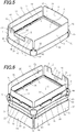
- the infant accommodation system 81 illustrated in Fig. 5 is in a different state to the infant accommodation system 81 illustrated in Fig. 4 .
- the infant accommodation system 81 illustrated in Fig. 5 is in a state in which the head side outer wall section 23 and the leg side outer wall section 24 of the infant accommodation system 81 illustrated in Fig. 4 have been exchanged with each other.
- the head side outer wall section 23 and the leg side outer wall section 24 are removed by performing a removal operation substantially similarly to, or substantially the same as, the removal of the leg side outer wall section 24 described above.
- the head side outer wall section 23 is attached as illustrated in Fig. 5 to the left and right pair of attachment members 46 to which the leg side outer wall section 24 is attached in Fig. 4
- the leg side outer wall section 24 is attached as illustrated in Fig. 5 to the left and right pair of attachment members 46 to which the head side outer wall section 23 is attached in Fig. 4 .
- the head side outer wall section 23 and the leg side outer wall section 24 can be exchanged with each other as illustrated in Fig. 1 , Fig. 4 , and Fig. 5 .
- the head side outer wall section 23 equipped with the cutout shaped indentation 31 and the grommet members 42 is adjacent to the ancillary equipment support column 22.
- the head of the infant is placed adjacent to the vicinity of inside the head side outer wall section 23, and the legs (in particular the feet) of the infant are placed adjacent to the vicinity of inside the leg side outer wall section 24.
- breathing tubes (not illustrated in the drawings) from resuscitation equipment (not illustrated in the drawings) can be extended, via the grommet members 42 of the head side outer wall section 23, to the proximity of the mouth of the infant.
- the doctor or nurse or the like needs to perform treatment in the proximity of the head of the infant from the vicinity of the support column 22. Note that in the normal operation state illustrated in Fig. 1 and Fig.
- the doctor or nurse or the like might conceivably perform treatment in the proximity of the head of the infant by switching over the head side of the infant and the leg side of the infant.
- breathing tubes from the resuscitation equipment extend over a comparatively long gap from the grommet members 42 on the head side outer wall section 23 to the proximity of the head of the infant.
- the breathing tubes accordingly may become twisted or kinked by the infant's own body movements, making it difficult to achieve a good supply of breathing gas from the breathing tubes to the infant.
- the head side outer wall section 23 is positioned at a distance from the support column 22, etc.
- the breathing tubes may be arranged to pass in the vicinity of the outer peripheral face of the outer wall section 25, 26 on the left side or the right side and pass through the grommet members 42.
- the left side outer wall section 25 and the right side outer wall section 26 may also be exchanged, if the need arises.
- the at least one outer wall section 23 to 26 can be replaced with a spare outer wall section.
- the leg side outer wall section 24 may also be similarly equipped with the grommet members 42 and the cutout shaped indentation 31.
- the outer wall sections 23, 24 are both respectively equipped with the grommet members 42 and the cutout shaped indentation 31
- the grommet members 42 and the cutout shaped indentation 31 that have been respectively provided at the leg side outer wall section 24 obstruct the doctor or nurse or the like, as well as there being a comparatively high cost from respectively providing two sets of the grommet members 42 and the cutout shaped indentation 31.
- the cutout shaped indentation 31 and the grommet members 42 are only respectively provided to one out of the head side outer wall section 23 and the leg side outer wall section 24. This thereby enables the four outer wall sections 23 to 26 to be provided at a comparatively low cost compared to cases in which the cutout shaped indentation 31 and the respective grommet members 42 are provided at both the head side outer wall section 23 and the leg side outer wall section 24.
- the present disclosure is applied to an open incubator.
- the present disclosure may be applied to not only an open incubator, but also to an open and close incubator.
- a substantially box-lid shaped upper hood that is capable of moving substantially upward and downward may be provided to enable the infant accommodation space 27 to be selectably covered from above.
- Such an upper hood may be configured with an upper face section that may be substantially transparent, and with upper side walls that may be substantially transparent, are substantially rectangular shaped when viewed in plan view, and project substantially downward from the vicinity of the outer periphery of the upper face section. Configuration can also be made such that the incubator becomes an open incubator by opening the upper face of the infant accommodation space 27 when the upper hood is raised, and becomes a closed incubator by closing the upper face of the infant accommodation space 27 when the upper hood is lowered.
- the mattress tray 16 is configured in a substantially rectangular shape in plan view.
- the mattress tray 16 may be configured so as to be a substantially circular shape, a substantially elliptical shape, a substantially oval shape, or the like in plan view.
- the mattress tray 16 may also be configured as any substantially polygonal shape or the like other than a substantially rectangular shape in plan view.
Landscapes
- Health & Medical Sciences (AREA)
- Gynecology & Obstetrics (AREA)
- Pediatric Medicine (AREA)
- Pregnancy & Childbirth (AREA)
- Life Sciences & Earth Sciences (AREA)
- Animal Behavior & Ethology (AREA)
- General Health & Medical Sciences (AREA)
- Public Health (AREA)
- Veterinary Medicine (AREA)
- Accommodation For Nursing Or Treatment Tables (AREA)
Claims (7)
- Incubateur comprenant :un plateau à matelas (16) pour accueillir un nourrisson couché dessus ;une base d'incubateur (15) sur laquelle est disposé le plateau à matelas (16) ;au moins une section de paroi extérieure (23, 24, 25, 26) qui est configurée pour entourer une proximité de la périphérie extérieure du plateau à matelas (16) ;un élément porteur (64) qui est disposé dans l'une de la base d'incubateur (15) ou dans l'au moins une section de paroi extérieure (23, 24, 25, 26) ; etun arbre de support pivotant (30) qui est disposé dans l'autre de la base d'incubateur (15) ou dans l'au moins une section de paroi extérieure (23, 24, 25, 26), l'arbre de support pivotant (30) étant configuré pour se déplacer d'avant en arrière dans une direction axiale substantielle de l'arbre de support pivotant (30) par rapport à l'au moins une section de paroi extérieure (23, 24, 25, 26) ; etun élément d'actionnement (45) pour actionner l'arbre de support pivotant (30), l'élément d'actionnement (45) est configuré de telle sorte que l'élément d'actionnement (45) est placé dans un état dans lequel un mouvement sensiblement linéaire vers l'avant est permis en raison de la rotation de l'élément d'actionnement (45) dans une direction, et l'arbre de support pivotant (30) est déverrouillé de l'élément porteur (64) en raison du déplacement sensiblement linéaire de l'élément d'actionnement (45) vers l'avant dans cet état.
- Incubateur selon la revendication 1, dans lequel l'élément d'actionnement (45) est disposé sur l'au moins une section de paroi extérieure (23, 24, 25, 26).
- Incubateur selon la revendication 1 ou 2, dans lequel l'au moins une section de paroi extérieure (23, 24, 25, 26) est configurée de telle sorte que, dans un état dans lequel l'arbre de support pivotant (30) est verrouillé par l'élément porteur (64), l'au moins une section de paroi extérieure (23, 24, 25, 26) peut pivoter individuellement en avant et en arrière, en utilisant l'arbre de support pivotant (30) comme point de pivot, entre un état dans lequel l'au moins une section de paroi extérieure (23, 24, 25, 26) est dirigée sensiblement vers le haut et est sensiblement verticale et un état dans lequel l'au moins une section de paroi extérieure (23, 24, 25, 26) est dirigée sensiblement vers le bas et pend sensiblement vers le bas.
- Incubateur selon l'une des revendications 1 à 3, dans lequel
l'au moins une section de paroi extérieure (23, 24, 25, 26) comprend une pluralité de sections de paroi extérieure (23, 24, 25, 26) qui est configurée pour entourer la proximité de la périphérie extérieure du plateau à matelas (16),
une première section de paroi extérieure (23) parmi la pluralité de sections de paroi extérieure (23, 24, 25, 26) comprend un élément de passage (42), et est configurée pour être fixée de manière détachable à un premier endroit de fixation disposé à proximité de la périphérie extérieure du plateau à matelas (16),
une deuxième section de paroi extérieure (24) parmi la pluralité de sections de paroi extérieure (23, 24, 25, 26) est configurée pour être fixée de manière détachable à un deuxième endroit de fixation disposé à proximité de la périphérie extérieure du plateau à matelas (16),
la première section de paroi extérieure (23) est en outre configurée pour être détachée du premier endroit de fixation et fixée au deuxième endroit de fixation, et
la deuxième section de paroi extérieure (24) est en outre configurée pour être détachée du deuxième endroit de fixation et fixée au premier endroit de fixation. - Incubateur selon la revendication 4, dans lequel l'au moins une section de paroi extérieure (23, 24, 25, 26) comprend une section de paroi extérieure avant qui est la deuxième section de paroi extérieure (24), une section de paroi extérieure arrière qui est la première section de paroi extérieure (23), une section de paroi extérieure gauche (25) et une section de paroi extérieure droite (26).
- Incubateur selon l'une des revendications 1 à 5, dans lequel un espace d'accueil pour un nourrisson (27) qui est de forme sensiblement rectangulaire en vue de dessus, est configuré par l'au moins une section de paroi extérieure (23, 24, 25, 26).
- Incubateur selon l'une des revendications 1 à 6, dans lequel l'incubateur (11) est un incubateur de type ouvert.
Applications Claiming Priority (2)
| Application Number | Priority Date | Filing Date | Title |
|---|---|---|---|
| JP2015223756A JP6181137B2 (ja) | 2015-11-16 | 2015-11-16 | 保育器 |
| EP16197965.3A EP3167862B1 (fr) | 2015-11-16 | 2016-11-09 | Incubateur |
Related Parent Applications (2)
| Application Number | Title | Priority Date | Filing Date |
|---|---|---|---|
| EP16197965.3A Division-Into EP3167862B1 (fr) | 2015-11-16 | 2016-11-09 | Incubateur |
| EP16197965.3A Division EP3167862B1 (fr) | 2015-11-16 | 2016-11-09 | Incubateur |
Publications (2)
| Publication Number | Publication Date |
|---|---|
| EP3560471A1 EP3560471A1 (fr) | 2019-10-30 |
| EP3560471B1 true EP3560471B1 (fr) | 2020-12-30 |
Family
ID=57256198
Family Applications (2)
| Application Number | Title | Priority Date | Filing Date |
|---|---|---|---|
| EP16197965.3A Active EP3167862B1 (fr) | 2015-11-16 | 2016-11-09 | Incubateur |
| EP19175087.6A Active EP3560471B1 (fr) | 2015-11-16 | 2016-11-09 | Incubateur |
Family Applications Before (1)
| Application Number | Title | Priority Date | Filing Date |
|---|---|---|---|
| EP16197965.3A Active EP3167862B1 (fr) | 2015-11-16 | 2016-11-09 | Incubateur |
Country Status (5)
| Country | Link |
|---|---|
| US (1) | US10588807B2 (fr) |
| EP (2) | EP3167862B1 (fr) |
| JP (1) | JP6181137B2 (fr) |
| CN (1) | CN106974791B (fr) |
| BR (1) | BR102016026582B1 (fr) |
Families Citing this family (4)
| Publication number | Priority date | Publication date | Assignee | Title |
|---|---|---|---|---|
| JP6117897B1 (ja) | 2015-11-25 | 2017-04-19 | アトムメディカル株式会社 | 保育器 |
| EP3675692B1 (fr) * | 2017-09-14 | 2023-05-10 | The University of North Carolina at Chapel Hill | Berceau |
| CN108635142A (zh) * | 2018-04-19 | 2018-10-12 | 国伟婷 | 新生儿呼吸暂停抢救装置 |
| JP2024064794A (ja) * | 2022-10-28 | 2024-05-14 | 株式会社坂本モデル | 保育器シミュレータ |
Family Cites Families (15)
| Publication number | Priority date | Publication date | Assignee | Title |
|---|---|---|---|---|
| US6155970A (en) * | 1998-07-20 | 2000-12-05 | Datex-Ohmeda, Inc. | Rotating infant mattress |
| US6234954B1 (en) * | 1999-12-11 | 2001-05-22 | Datex-Ohmeda, Inc. | Infant care apparatus with removable door |
| US6336897B1 (en) * | 1999-12-11 | 2002-01-08 | Datex-Ohmeda, Inc. | Grommet for infant care apparatus |
| JP2003047634A (ja) * | 2001-08-07 | 2003-02-18 | Atom Medical Corp | 保育器用マットレス、保育器用マットレス付き臥床架および保育器 |
| US6761683B2 (en) * | 2001-08-27 | 2004-07-13 | Hill-Rom Services, Inc. | Integrated scale with underlying x-ray tray |
| US8602963B2 (en) * | 2007-12-04 | 2013-12-10 | Draeger Medical Systems, Inc. | Warming therapy device including retractable hood member |
| WO2009073699A1 (fr) * | 2007-12-04 | 2009-06-11 | Draeger Medical Systems, Inc. | Dispositif de traitement par la chaleur muni d'une porte à charnière permettant l'accès d'un patient |
| JP5123082B2 (ja) * | 2008-07-03 | 2013-01-16 | アトムメディカル株式会社 | 保育器におけるグロメット構造 |
| JP5791099B2 (ja) * | 2011-04-15 | 2015-10-07 | サミー株式会社 | 遊技機 |
| JP5694839B2 (ja) * | 2011-04-19 | 2015-04-01 | アトムメディカル株式会社 | 保育器における可動壁部取り付け機構 |
| JP5945452B2 (ja) * | 2012-05-15 | 2016-07-05 | アトムメディカル株式会社 | 保育器 |
| JP2014003369A (ja) * | 2012-06-15 | 2014-01-09 | Panasonic Corp | 無線通信端末装置及びモビリティ制御方法 |
| JP5960527B2 (ja) * | 2012-07-06 | 2016-08-02 | アトムメディカル株式会社 | 保育器 |
| JP5965242B2 (ja) * | 2012-08-08 | 2016-08-03 | アトムメディカル株式会社 | 保育器の臥床台および臥床台付き保育器ならびに保育器の臥床台の使用方法 |
| MX359197B (es) * | 2012-12-11 | 2018-09-19 | Koninklijke Philips Nv | Bisagra mejorada y metodo para conectar de forma pivotante y removible un miembro con una estructura. |
-
2015
- 2015-11-16 JP JP2015223756A patent/JP6181137B2/ja active Active
-
2016
- 2016-11-09 EP EP16197965.3A patent/EP3167862B1/fr active Active
- 2016-11-09 EP EP19175087.6A patent/EP3560471B1/fr active Active
- 2016-11-10 US US15/348,318 patent/US10588807B2/en active Active
- 2016-11-11 BR BR102016026582-7A patent/BR102016026582B1/pt active IP Right Grant
- 2016-11-11 CN CN201610994879.5A patent/CN106974791B/zh active Active
Non-Patent Citations (1)
| Title |
|---|
| None * |
Also Published As
| Publication number | Publication date |
|---|---|
| US20170135887A1 (en) | 2017-05-18 |
| EP3167862B1 (fr) | 2020-04-15 |
| CN106974791A (zh) | 2017-07-25 |
| JP2017086737A (ja) | 2017-05-25 |
| EP3560471A1 (fr) | 2019-10-30 |
| JP6181137B2 (ja) | 2017-08-16 |
| BR102016026582A2 (pt) | 2017-05-23 |
| US10588807B2 (en) | 2020-03-17 |
| BR102016026582B1 (pt) | 2022-05-31 |
| CN106974791B (zh) | 2020-09-25 |
| EP3167862A1 (fr) | 2017-05-17 |
Similar Documents
| Publication | Publication Date | Title |
|---|---|---|
| EP3167862B1 (fr) | Incubateur | |
| JP5965242B2 (ja) | 保育器の臥床台および臥床台付き保育器ならびに保育器の臥床台の使用方法 | |
| EP2514399B1 (fr) | Mécanisme de fixation de portion de paroi mobile d'incubateur | |
| EP3181109B1 (fr) | Incubateur avec tampon | |
| US10064775B2 (en) | Incubator | |
| EP3170488B1 (fr) | Incubateur | |
| KR101826092B1 (ko) | 보육기 | |
| JP5960527B2 (ja) | 保育器 | |
| JP6047251B1 (ja) | 保育器 | |
| EP3165204B1 (fr) | Incubateur | |
| JP6117897B1 (ja) | 保育器 | |
| US12509928B2 (en) | Side panel latch assembly for an incubator | |
| JP2017123905A (ja) | 保育器 | |
| KR102032436B1 (ko) | 조작의 편리성과 시인성이 향상된 의료용 침대의 보호구 및 이를 포함하는 침대 |
Legal Events
| Date | Code | Title | Description |
|---|---|---|---|
| PUAI | Public reference made under article 153(3) epc to a published international application that has entered the european phase |
Free format text: ORIGINAL CODE: 0009012 |
|
| STAA | Information on the status of an ep patent application or granted ep patent |
Free format text: STATUS: THE APPLICATION HAS BEEN PUBLISHED |
|
| AC | Divisional application: reference to earlier application |
Ref document number: 3167862 Country of ref document: EP Kind code of ref document: P |
|
| AK | Designated contracting states |
Kind code of ref document: A1 Designated state(s): AL AT BE BG CH CY CZ DE DK EE ES FI FR GB GR HR HU IE IS IT LI LT LU LV MC MK MT NL NO PL PT RO RS SE SI SK SM TR |
|
| STAA | Information on the status of an ep patent application or granted ep patent |
Free format text: STATUS: REQUEST FOR EXAMINATION WAS MADE |
|
| 17P | Request for examination filed |
Effective date: 20200217 |
|
| RBV | Designated contracting states (corrected) |
Designated state(s): AL AT BE BG CH CY CZ DE DK EE ES FI FR GB GR HR HU IE IS IT LI LT LU LV MC MK MT NL NO PL PT RO RS SE SI SK SM TR |
|
| GRAP | Despatch of communication of intention to grant a patent |
Free format text: ORIGINAL CODE: EPIDOSNIGR1 |
|
| STAA | Information on the status of an ep patent application or granted ep patent |
Free format text: STATUS: GRANT OF PATENT IS INTENDED |
|
| INTG | Intention to grant announced |
Effective date: 20200716 |
|
| GRAS | Grant fee paid |
Free format text: ORIGINAL CODE: EPIDOSNIGR3 |
|
| GRAA | (expected) grant |
Free format text: ORIGINAL CODE: 0009210 |
|
| STAA | Information on the status of an ep patent application or granted ep patent |
Free format text: STATUS: THE PATENT HAS BEEN GRANTED |
|
| AC | Divisional application: reference to earlier application |
Ref document number: 3167862 Country of ref document: EP Kind code of ref document: P |
|
| AK | Designated contracting states |
Kind code of ref document: B1 Designated state(s): AL AT BE BG CH CY CZ DE DK EE ES FI FR GB GR HR HU IE IS IT LI LT LU LV MC MK MT NL NO PL PT RO RS SE SI SK SM TR |
|
| REG | Reference to a national code |
Ref country code: GB Ref legal event code: FG4D |
|
| REG | Reference to a national code |
Ref country code: AT Ref legal event code: REF Ref document number: 1349193 Country of ref document: AT Kind code of ref document: T Effective date: 20210115 |
|
| REG | Reference to a national code |
Ref country code: DE Ref legal event code: R096 Ref document number: 602016050867 Country of ref document: DE |
|
| REG | Reference to a national code |
Ref country code: IE Ref legal event code: FG4D |
|
| PG25 | Lapsed in a contracting state [announced via postgrant information from national office to epo] |
Ref country code: RS Free format text: LAPSE BECAUSE OF FAILURE TO SUBMIT A TRANSLATION OF THE DESCRIPTION OR TO PAY THE FEE WITHIN THE PRESCRIBED TIME-LIMIT Effective date: 20201230 Ref country code: FI Free format text: LAPSE BECAUSE OF FAILURE TO SUBMIT A TRANSLATION OF THE DESCRIPTION OR TO PAY THE FEE WITHIN THE PRESCRIBED TIME-LIMIT Effective date: 20201230 Ref country code: NO Free format text: LAPSE BECAUSE OF FAILURE TO SUBMIT A TRANSLATION OF THE DESCRIPTION OR TO PAY THE FEE WITHIN THE PRESCRIBED TIME-LIMIT Effective date: 20210330 Ref country code: GR Free format text: LAPSE BECAUSE OF FAILURE TO SUBMIT A TRANSLATION OF THE DESCRIPTION OR TO PAY THE FEE WITHIN THE PRESCRIBED TIME-LIMIT Effective date: 20210331 |
|
| REG | Reference to a national code |
Ref country code: AT Ref legal event code: MK05 Ref document number: 1349193 Country of ref document: AT Kind code of ref document: T Effective date: 20201230 |
|
| PG25 | Lapsed in a contracting state [announced via postgrant information from national office to epo] |
Ref country code: LV Free format text: LAPSE BECAUSE OF FAILURE TO SUBMIT A TRANSLATION OF THE DESCRIPTION OR TO PAY THE FEE WITHIN THE PRESCRIBED TIME-LIMIT Effective date: 20201230 Ref country code: SE Free format text: LAPSE BECAUSE OF FAILURE TO SUBMIT A TRANSLATION OF THE DESCRIPTION OR TO PAY THE FEE WITHIN THE PRESCRIBED TIME-LIMIT Effective date: 20201230 Ref country code: BG Free format text: LAPSE BECAUSE OF FAILURE TO SUBMIT A TRANSLATION OF THE DESCRIPTION OR TO PAY THE FEE WITHIN THE PRESCRIBED TIME-LIMIT Effective date: 20210330 |
|
| REG | Reference to a national code |
Ref country code: NL Ref legal event code: MP Effective date: 20201230 |
|
| PG25 | Lapsed in a contracting state [announced via postgrant information from national office to epo] |
Ref country code: HR Free format text: LAPSE BECAUSE OF FAILURE TO SUBMIT A TRANSLATION OF THE DESCRIPTION OR TO PAY THE FEE WITHIN THE PRESCRIBED TIME-LIMIT Effective date: 20201230 |
|
| REG | Reference to a national code |
Ref country code: LT Ref legal event code: MG9D |
|
| PG25 | Lapsed in a contracting state [announced via postgrant information from national office to epo] |
Ref country code: LT Free format text: LAPSE BECAUSE OF FAILURE TO SUBMIT A TRANSLATION OF THE DESCRIPTION OR TO PAY THE FEE WITHIN THE PRESCRIBED TIME-LIMIT Effective date: 20201230 Ref country code: RO Free format text: LAPSE BECAUSE OF FAILURE TO SUBMIT A TRANSLATION OF THE DESCRIPTION OR TO PAY THE FEE WITHIN THE PRESCRIBED TIME-LIMIT Effective date: 20201230 Ref country code: PT Free format text: LAPSE BECAUSE OF FAILURE TO SUBMIT A TRANSLATION OF THE DESCRIPTION OR TO PAY THE FEE WITHIN THE PRESCRIBED TIME-LIMIT Effective date: 20210430 Ref country code: SK Free format text: LAPSE BECAUSE OF FAILURE TO SUBMIT A TRANSLATION OF THE DESCRIPTION OR TO PAY THE FEE WITHIN THE PRESCRIBED TIME-LIMIT Effective date: 20201230 Ref country code: EE Free format text: LAPSE BECAUSE OF FAILURE TO SUBMIT A TRANSLATION OF THE DESCRIPTION OR TO PAY THE FEE WITHIN THE PRESCRIBED TIME-LIMIT Effective date: 20201230 Ref country code: CZ Free format text: LAPSE BECAUSE OF FAILURE TO SUBMIT A TRANSLATION OF THE DESCRIPTION OR TO PAY THE FEE WITHIN THE PRESCRIBED TIME-LIMIT Effective date: 20201230 |
|
| PG25 | Lapsed in a contracting state [announced via postgrant information from national office to epo] |
Ref country code: AT Free format text: LAPSE BECAUSE OF FAILURE TO SUBMIT A TRANSLATION OF THE DESCRIPTION OR TO PAY THE FEE WITHIN THE PRESCRIBED TIME-LIMIT Effective date: 20201230 Ref country code: PL Free format text: LAPSE BECAUSE OF FAILURE TO SUBMIT A TRANSLATION OF THE DESCRIPTION OR TO PAY THE FEE WITHIN THE PRESCRIBED TIME-LIMIT Effective date: 20201230 |
|
| PG25 | Lapsed in a contracting state [announced via postgrant information from national office to epo] |
Ref country code: IS Free format text: LAPSE BECAUSE OF FAILURE TO SUBMIT A TRANSLATION OF THE DESCRIPTION OR TO PAY THE FEE WITHIN THE PRESCRIBED TIME-LIMIT Effective date: 20210430 |
|
| REG | Reference to a national code |
Ref country code: DE Ref legal event code: R097 Ref document number: 602016050867 Country of ref document: DE |
|
| PG25 | Lapsed in a contracting state [announced via postgrant information from national office to epo] |
Ref country code: AL Free format text: LAPSE BECAUSE OF FAILURE TO SUBMIT A TRANSLATION OF THE DESCRIPTION OR TO PAY THE FEE WITHIN THE PRESCRIBED TIME-LIMIT Effective date: 20201230 Ref country code: IT Free format text: LAPSE BECAUSE OF FAILURE TO SUBMIT A TRANSLATION OF THE DESCRIPTION OR TO PAY THE FEE WITHIN THE PRESCRIBED TIME-LIMIT Effective date: 20201230 |
|
| PLBE | No opposition filed within time limit |
Free format text: ORIGINAL CODE: 0009261 |
|
| STAA | Information on the status of an ep patent application or granted ep patent |
Free format text: STATUS: NO OPPOSITION FILED WITHIN TIME LIMIT |
|
| PG25 | Lapsed in a contracting state [announced via postgrant information from national office to epo] |
Ref country code: DK Free format text: LAPSE BECAUSE OF FAILURE TO SUBMIT A TRANSLATION OF THE DESCRIPTION OR TO PAY THE FEE WITHIN THE PRESCRIBED TIME-LIMIT Effective date: 20201230 |
|
| 26N | No opposition filed |
Effective date: 20211001 |
|
| PG25 | Lapsed in a contracting state [announced via postgrant information from national office to epo] |
Ref country code: ES Free format text: LAPSE BECAUSE OF FAILURE TO SUBMIT A TRANSLATION OF THE DESCRIPTION OR TO PAY THE FEE WITHIN THE PRESCRIBED TIME-LIMIT Effective date: 20201230 |
|
| PG25 | Lapsed in a contracting state [announced via postgrant information from national office to epo] |
Ref country code: SI Free format text: LAPSE BECAUSE OF FAILURE TO SUBMIT A TRANSLATION OF THE DESCRIPTION OR TO PAY THE FEE WITHIN THE PRESCRIBED TIME-LIMIT Effective date: 20201230 |
|
| PG25 | Lapsed in a contracting state [announced via postgrant information from national office to epo] |
Ref country code: IS Free format text: LAPSE BECAUSE OF FAILURE TO SUBMIT A TRANSLATION OF THE DESCRIPTION OR TO PAY THE FEE WITHIN THE PRESCRIBED TIME-LIMIT Effective date: 20210430 |
|
| PG25 | Lapsed in a contracting state [announced via postgrant information from national office to epo] |
Ref country code: MC Free format text: LAPSE BECAUSE OF FAILURE TO SUBMIT A TRANSLATION OF THE DESCRIPTION OR TO PAY THE FEE WITHIN THE PRESCRIBED TIME-LIMIT Effective date: 20201230 |
|
| REG | Reference to a national code |
Ref country code: CH Ref legal event code: PL |
|
| GBPC | Gb: european patent ceased through non-payment of renewal fee |
Effective date: 20211109 |
|
| PG25 | Lapsed in a contracting state [announced via postgrant information from national office to epo] |
Ref country code: LU Free format text: LAPSE BECAUSE OF NON-PAYMENT OF DUE FEES Effective date: 20211109 Ref country code: BE Free format text: LAPSE BECAUSE OF NON-PAYMENT OF DUE FEES Effective date: 20211130 |
|
| REG | Reference to a national code |
Ref country code: BE Ref legal event code: MM Effective date: 20211130 |
|
| PG25 | Lapsed in a contracting state [announced via postgrant information from national office to epo] |
Ref country code: LI Free format text: LAPSE BECAUSE OF NON-PAYMENT OF DUE FEES Effective date: 20211130 Ref country code: CH Free format text: LAPSE BECAUSE OF NON-PAYMENT OF DUE FEES Effective date: 20211130 |
|
| REG | Reference to a national code |
Ref country code: DE Ref legal event code: R082 Ref document number: 602016050867 Country of ref document: DE Representative=s name: BALS & VOGEL PATENTANWAELTE PARTG MBB, DE |
|
| PG25 | Lapsed in a contracting state [announced via postgrant information from national office to epo] |
Ref country code: IE Free format text: LAPSE BECAUSE OF NON-PAYMENT OF DUE FEES Effective date: 20211109 Ref country code: GB Free format text: LAPSE BECAUSE OF NON-PAYMENT OF DUE FEES Effective date: 20211109 |
|
| PG25 | Lapsed in a contracting state [announced via postgrant information from national office to epo] |
Ref country code: FR Free format text: LAPSE BECAUSE OF NON-PAYMENT OF DUE FEES Effective date: 20211130 |
|
| PG25 | Lapsed in a contracting state [announced via postgrant information from national office to epo] |
Ref country code: NL Free format text: LAPSE BECAUSE OF NON-PAYMENT OF DUE FEES Effective date: 20201230 Ref country code: CY Free format text: LAPSE BECAUSE OF FAILURE TO SUBMIT A TRANSLATION OF THE DESCRIPTION OR TO PAY THE FEE WITHIN THE PRESCRIBED TIME-LIMIT Effective date: 20201230 |
|
| PG25 | Lapsed in a contracting state [announced via postgrant information from national office to epo] |
Ref country code: SM Free format text: LAPSE BECAUSE OF FAILURE TO SUBMIT A TRANSLATION OF THE DESCRIPTION OR TO PAY THE FEE WITHIN THE PRESCRIBED TIME-LIMIT Effective date: 20201230 Ref country code: HU Free format text: LAPSE BECAUSE OF FAILURE TO SUBMIT A TRANSLATION OF THE DESCRIPTION OR TO PAY THE FEE WITHIN THE PRESCRIBED TIME-LIMIT; INVALID AB INITIO Effective date: 20161109 |
|
| PG25 | Lapsed in a contracting state [announced via postgrant information from national office to epo] |
Ref country code: MK Free format text: LAPSE BECAUSE OF FAILURE TO SUBMIT A TRANSLATION OF THE DESCRIPTION OR TO PAY THE FEE WITHIN THE PRESCRIBED TIME-LIMIT Effective date: 20201230 |
|
| PG25 | Lapsed in a contracting state [announced via postgrant information from national office to epo] |
Ref country code: TR Free format text: LAPSE BECAUSE OF FAILURE TO SUBMIT A TRANSLATION OF THE DESCRIPTION OR TO PAY THE FEE WITHIN THE PRESCRIBED TIME-LIMIT Effective date: 20201230 |
|
| PG25 | Lapsed in a contracting state [announced via postgrant information from national office to epo] |
Ref country code: MT Free format text: LAPSE BECAUSE OF FAILURE TO SUBMIT A TRANSLATION OF THE DESCRIPTION OR TO PAY THE FEE WITHIN THE PRESCRIBED TIME-LIMIT Effective date: 20201230 |
|
| PGFP | Annual fee paid to national office [announced via postgrant information from national office to epo] |
Ref country code: DE Payment date: 20251119 Year of fee payment: 10 |