EP3560738B1 - Dispositif d'écoulement d'air - Google Patents
Dispositif d'écoulement d'air Download PDFInfo
- Publication number
- EP3560738B1 EP3560738B1 EP18212521.1A EP18212521A EP3560738B1 EP 3560738 B1 EP3560738 B1 EP 3560738B1 EP 18212521 A EP18212521 A EP 18212521A EP 3560738 B1 EP3560738 B1 EP 3560738B1
- Authority
- EP
- European Patent Office
- Prior art keywords
- air
- section
- blade
- decorative element
- slat
- Prior art date
- Legal status (The legal status is an assumption and is not a legal conclusion. Google has not performed a legal analysis and makes no representation as to the accuracy of the status listed.)
- Active
Links
Images




Classifications
-
- B—PERFORMING OPERATIONS; TRANSPORTING
- B60—VEHICLES IN GENERAL
- B60H—ARRANGEMENTS OF HEATING, COOLING, VENTILATING OR OTHER AIR-TREATING DEVICES SPECIALLY ADAPTED FOR PASSENGER OR GOODS SPACES OF VEHICLES
- B60H1/00—Heating, cooling or ventilating devices
- B60H1/34—Nozzles; Air-diffusers
- B60H1/3414—Nozzles; Air-diffusers with means for adjusting the air stream direction
- B60H1/3421—Nozzles; Air-diffusers with means for adjusting the air stream direction using only pivoting shutters
-
- B—PERFORMING OPERATIONS; TRANSPORTING
- B60—VEHICLES IN GENERAL
- B60H—ARRANGEMENTS OF HEATING, COOLING, VENTILATING OR OTHER AIR-TREATING DEVICES SPECIALLY ADAPTED FOR PASSENGER OR GOODS SPACES OF VEHICLES
- B60H1/00—Heating, cooling or ventilating devices
- B60H1/34—Nozzles; Air-diffusers
- B60H1/3414—Nozzles; Air-diffusers with means for adjusting the air stream direction
-
- B—PERFORMING OPERATIONS; TRANSPORTING
- B60—VEHICLES IN GENERAL
- B60H—ARRANGEMENTS OF HEATING, COOLING, VENTILATING OR OTHER AIR-TREATING DEVICES SPECIALLY ADAPTED FOR PASSENGER OR GOODS SPACES OF VEHICLES
- B60H1/00—Heating, cooling or ventilating devices
- B60H1/34—Nozzles; Air-diffusers
- B60H2001/3471—Details of actuators
-
- F—MECHANICAL ENGINEERING; LIGHTING; HEATING; WEAPONS; BLASTING
- F24—HEATING; RANGES; VENTILATING
- F24F—AIR-CONDITIONING; AIR-HUMIDIFICATION; VENTILATION; USE OF AIR CURRENTS FOR SCREENING
- F24F13/00—Details common to, or for air-conditioning, air-humidification, ventilation or use of air currents for screening
- F24F13/08—Air-flow control members, e.g. louvres, grilles, flaps or guide plates
- F24F13/10—Air-flow control members, e.g. louvres, grilles, flaps or guide plates movable, e.g. dampers
- F24F13/14—Air-flow control members, e.g. louvres, grilles, flaps or guide plates movable, e.g. dampers built up of tilting members, e.g. louvre
- F24F13/1413—Air-flow control members, e.g. louvres, grilles, flaps or guide plates movable, e.g. dampers built up of tilting members, e.g. louvre using more than one tilting member, e.g. with several pivoting blades
-
- F—MECHANICAL ENGINEERING; LIGHTING; HEATING; WEAPONS; BLASTING
- F24—HEATING; RANGES; VENTILATING
- F24F—AIR-CONDITIONING; AIR-HUMIDIFICATION; VENTILATION; USE OF AIR CURRENTS FOR SCREENING
- F24F13/00—Details common to, or for air-conditioning, air-humidification, ventilation or use of air currents for screening
- F24F13/08—Air-flow control members, e.g. louvres, grilles, flaps or guide plates
- F24F13/10—Air-flow control members, e.g. louvres, grilles, flaps or guide plates movable, e.g. dampers
- F24F13/14—Air-flow control members, e.g. louvres, grilles, flaps or guide plates movable, e.g. dampers built up of tilting members, e.g. louvre
- F24F13/15—Air-flow control members, e.g. louvres, grilles, flaps or guide plates movable, e.g. dampers built up of tilting members, e.g. louvre with parallel simultaneously tiltable lamellae
Definitions
- the invention relates to an air vent which has a housing with an air duct in which a decorative element, at least one first slat and at least one second slat are arranged.
- Air vents are used to dispense air supplied by an air conditioning system or other ventilation device. Air vents can also be used to divert the dispensed air. In vehicles, air vents are used to bring fresh air, tempered air and/or conditioned air into the passenger compartment of a vehicle. Vehicles can be, for example, motor vehicles such as cars, trucks or buses, trains, airplanes or ships.
- a throttle device can be provided for this purpose.
- the throttle device can regulate the amount of air supplied via a control device, whereby the control device can be arranged or coupled with an operating device for deflecting the air flow or separately from such an operating device.
- an operating device can for example, in the area of an outflow opening.
- Air vents in motor vehicles can be arranged in different positions.
- air vents in motor vehicles are located in the area of a vehicle dashboard or in the area of the A, B or C pillar as well as on the roof or in other places.
- Air outlets with a very low outlet height compared to their outlet width (and vice versa) are known from the prior art.
- the air outlets are also referred to as joint outlets.
- Such air outlets have, for example, egg-shaped air guide elements that are arranged rigidly in an air duct section, i.e. not movable, with air ducts being formed between the air guide element and the opposite wall sections. Air can be supplied to these air ducts alternately or together, with the supply of air to one of the areas taking place via a wing that is pivotably mounted on the back of the air guide element.
- Such an air vent is used, for example, in DE 10 2013 210 055 B3 described.
- this air vent has slats that are arranged in front of the wing in the direction of air flow and at a distance from it.
- These wings are also located in a section of the air duct that is separate from the section of the air duct in which the air deflection takes place via the wing and the air guide element.
- the air vent has various disadvantages. Firstly, the lateral air deflection via the slats, which are spaced apart in the direction of air flow and positioned in front, is inadequate. The air emitted can only be deflected laterally to a very small extent via the slats.
- the air guide element and the wing of the air outlet of DE 10 2013 210 055 B3 are designed in all disclosed embodiments and in the claimed embodiment as an air guide element that is made up of two components, namely the rigid air guide element and the wing arranged movably on the rear side.
- the design of such an elongated air guide element with a movable rear side has a number of disadvantages, as explained above.
- the DE 102 02 926 A1 discloses an air nozzle with a pivoting guide element.
- the guide element serves for air deflection and is mounted in a section with curved side walls.
- an adjusting element is coupled to the guide element, so that the guide element pivots in the opposite direction when the adjusting element is pivoted.
- a downward air flow can be generated, for example, by pivoting the adjusting element downwards.
- the US 2008 0 146 139 A1 , WO 2016 / 075 111 A1 , DE 20 2012 100 243 U1 and US 2011 0 319 005 A1 each disclose an air outlet which has at least one first slat in the area of the air outlet opening and second slats arranged transversely thereto behind it.
- An actuating element enables the first and second slats to be adjusted in order to influence the direction of the air flow exiting the outlet.
- a throttle device can be provided in the area of the air inlet of the outlet, which allows the air flow introduced into the outlet to be regulated.
- the object of the invention is to provide an air vent which has a very simple structure compared to the prior art, eliminates the problems of the prior art and represents an alternative solution to the air vents known from the prior art.
- the arrangement enables an improved lateral air deflection compared to the prior art, since the air deflection takes place closer to the area of the air outlet opening.
- the second slat which is intended to direct air flowing in via the air inlet opening into the first and the second region of the at least one first slat, the at least one first slat is positioned in front of the air flow direction and is located in the region of an air inlet opening for the air duct.
- the air is deflected via the second slat in a rear section of the air duct in a front section facing the air outlet opening via the formation of the wall sections in the housing.
- air can be diverted via the air guide element in conjunction with the wall sections.
- air vents with a very low air outlet height compared to an air outlet width (so-called joint vents)
- air diversion via the second slat is sufficient and can be provided to the same extent as, for example, in the prior art if the device required for this (second slat) for diverting the incoming air flow is arranged at a significant distance from the decorative element or an air guide element.
- Incoming air is first guided via the second slat into a first and/or second area of the at least one first slat according to the position of the second slat.
- a first air diversion takes place here, for example upwards and downwards.
- the air is then diverted sideways depending on the supply to the two areas of the at least one first slat. Since the lateral deflection occurs in a front section of the air duct facing the air outlet opening, it is maintained and is not weakened by additional air deflection via the curvature of the opposite side walls.
- the decorative element extends in the longitudinal direction of the air outlet opening and can only serve as an air guide element if the decorative element is moved (e.g. as an additional slat). There is also no air deflection via the decorative element if it is designed as a roller or cylinder, since the distance to the housing walls is not changed by turning the decorative element.
- the air deflection is regulated by the at least one second slat, which specifies the supply to the various areas of the at least one first slat. The air then flows along the opposite wall sections and is deflected downwards, for example, if the air flow is lower in a lower area of the air duct.
- the air flow is larger in the upper area, so that the larger air flow determines the direction of the air discharged by superimposing the partial air flows.
- Tests have shown that the air deflection is based on the design of the opposite wall sections, with the opposite wall sections running parallel to the decorative element and parallel to the pivot axis of the second slat.
- the decorative element therefore has no effect on the air deflection and therefore cannot technically be understood as an air guiding element, since no air deflection and no "air conduction" takes place via it.
- the decorative element is designed as a further slat and is pivotably mounted in opposite housing walls of the housing, it can be referred to as an air guiding element. However, this is not the case in versions with a rigidly arranged decorative element.
- the decorative element can further serve to conceal a coupling area of several first slats and can be provided as a bearing for an operating element which is pivotably and/or displaceably mounted.
- the decorative element can have different cross-sectional shapes and extends over the larger width of the air outlet opening.
- the decorative element is Essentially arranged in such a way that it extends centrally over the air outlet opening.
- the air vent described here therefore represents a different concept than, for example, in DE 10 2013 210 055 B3 described.
- the design known in the prior art discloses a substantially elongated air guide element, consisting of a rigidly arranged air guide element and a wing movably arranged on it.
- lateral air deflection is only possible to a very limited extent with this system, since on the one hand there is a long flow path for the air that has already been deflected laterally over the air guide element and on the other hand the laterally deflected air is additionally subordinate to the air deflection over the wing, with the air deflection over the wing taking place after the lateral air deflection.
- second lamellas can be pivotably mounted on or in the housing, which cause air deflection orthogonally to the air deflection via the at least one first lamella.
- the second lamella can also be formed from at least two interconnected partial lamellas or sections. A connection can be made, for example, via a film hinge or a pivot bearing.
- the at least one second lamella can also be designed as a so-called flexible lamella. Flexible lamellas are deformable and can be made of a flexible material. The flexible lamella can then be deformed via a device to deflect the air.
- the air outlet can also have a throttle device that serves to regulate the amount of air supplied.
- the throttle device can have two shell-like elements that are mounted so that they can pivot relative to one another, so that the air channel is closed by moving towards one another. This has the advantage that the throttle device itself does not cause any air deflection when throttled.
- the housing of the air outlet can have rounded air outlet edges in the area of the air outlet opening, which are designed in such a way that an air flow expansion can be achieved by utilizing the Coanda effect and the air deflection is supported.
- the air deflection orthogonal to the at least one first slat is thereby additionally improved.
- the decorative element can be curved at its end facing the air inlet opening and/or at its end facing the air outlet opening in such a way that an expansion of the air flow can be achieved by utilizing the Coanda effect.
- the air deflection can also be additionally supported.
- the decorative element can be mounted so that it can be displaced in the direction of air flow and can then also serve as an air guide element. This creates the possibility of providing a diffuse or spot-heavy air flow.
- a diffuse air flow can be provided, with the air guide element being at a first distance from the air outlet opening or the wall sections of the air duct in this area.
- a diffuse air flow can be emitted, with the expansion of the air flow being supported, for example, via rounded air outlet edges to provide the diffuse air flow.
- the air guide element is moved to a second distance from the air outlet opening or the wall sections of the air duct in this area, a spot-heavy air flow can be provided, with the outflowing air being bundled differently than at the first distance of the air guide element from the air outlet opening.
- the emitted air hits different areas of the air guide element.
- the emitted air flow is then emitted differently if the air guide element has differently designed areas.
- the movable mounting of the air guide element provides an additional control option for the air flow output.
- the distance of the air guide element allows the flow cross-section in the area of the air outlet opening between the air guide element and the housing to be changed accordingly so that a diffuse air flow or a spot-heavy air flow is provided.
- the decorative element can either be mounted rigidly in the housing of the air outlet or can be mounted in a movable manner, for example, so that it can be moved or pivoted, in the housing and then function as an air guide element.
- An air guide element can be mounted in the housing so that it can pivot
- the flow cross-section between the air guide element and the opposite wall sections of the air duct can be changed by pivoting the air guide element, analogous to a displacement of the air guide element.
- the air deflection orthogonal to the at least one first slat is thereby further improved.
- a pivotable air guide element supports the air deflection, since the air guide surface, along which a main air stream can flow, extends in the direction that was selected for air deflection by pivoting the air guide element.
- the air vent With the air vent, two partial air flows are created in the air outlet area, which can meet each other.
- the air is deflected, for example upwards or downwards, depending on the air directed into the corresponding areas between the decorative element and the opposite wall sections.
- the arrangement with a second slat, which is arranged in front of the at least one first slat in the direction of air flow also offers the advantage over known designs from the prior art that no noise is generated due to pressure losses, since incoming air, due to the arrangement of the at least one first slat in front of the decorative element in the direction of air flow, also allows air to be distributed in an area of the air duct that would be closed if the second slat were arranged directly on the decorative element.
- the at least one first slat therefore ensures that air can flow between the decorative element in all positions of the second slat. and the opposite wall section. However, the air flowing in between only accounts for a small proportion of the total air flow when the second slat is in the maximum pivoted position and therefore does not cause any additional air deflection.
- the decorative element can additionally have a cross-sectional shape with curved sections that are designed in such a way that a permanent air flow expansion can be achieved.
- the decorative element has correspondingly curved sections.
- the air vent can have an operating element that is movably mounted on and/or in the decorative element and is coupled to the at least one first slat and/or the second slat.
- this can cause the second slat to pivot in the opposite direction when pivoted.
- gear sections can be provided, with a first gear section being arranged on the air guide element and a second gear section being arranged on the second slat or coupled to them, and the gear sections being in engagement with one another.
- an operating element can be provided that only acts on the second slat when the decorative element is rigidly arranged or mounted so that it can be displaced in the direction of air flow.
- the at least one first slat can also be pivoted using an operating element.
- the operating element can be mounted on a rigidly or movably arranged decorative element so that it can be displaced in the longitudinal direction of the decorative element.
- the pivoting of at least one first slat is then achieved via a coupling device.
- the air vent can have a plurality of first slats, with the second slat having a plurality of coupling sections via which the first slats are connected to the second slat.
- the second slat can serve as a driver for pivoting the first slats in addition to its air guiding function. The design of the air vent is thereby further simplified.
- the air vent can also have a plurality of first slats, the first slats having a recess on their front side facing the air outlet opening and surrounding the decorative element at least in sections at the back.
- the sections of the first slats which surround the decorative element at least in sections are located in the first area and in the second area of the first slat. The lateral air deflection via the first slats is thereby further improved, since the first slats are directed further in the direction of the air outlet opening.
- the entire flow cross-section of the air duct can be changed via the at least one second lamella.
- the flow cross-section in a neutral position of the at least one second slat in the first section corresponds to the flow cross-section in the second section.
- the decorative element can be located in a central section.
- the air deflection via appropriately designed wall sections that have a curvature is also improved with a central decorative element.
- the at least one first slat is arranged in a section that is located in the transition from the first section to the second section according to the invention.
- the flow cross-section of the air duct and/or the flow cross-section of the decorative element can be designed such that the cross-sectional area in the section of the air duct due to the decorative element is a maximum of 20% smaller than the cross-sectional area of the air duct in the second section behind it.
- the air vent can be illuminated.
- components of the air vent can consist of a plastic that is at least partially translucent and, for example, have a coating that leaves only one area free for illumination.
- translucent plastics can also be used.
- the illumination can be provided by light guides and/or lighting elements, such as light-emitting diodes.
- the lighting can be controlled in such a way that the lighting is changed depending on the temperature of the air flowing out and the amount of air. A change in the Lighting depending on weather, light and daytime conditions may be provided.
- the components of the air vent can be made of plastic and can therefore be produced cost-effectively in large quantities using an injection molding process.
- the air vent has several advantages over known designs, as improved lateral air deflection is achieved and noise is prevented by completely closing off partial air ducts.
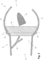
- the Fig. 1 to 3 show various designs of an air vent 10.
- air vents 10 can be arranged, for example, in a dashboard of a vehicle.
- the air vents 10 are designed as joint vents and therefore have a low discharge height with a large discharge width.
- the joint vents can also be arranged in such a way that the larger extent of the air outlet opening extends essentially vertically or at an angle.
- the air vents 10 of the first to third embodiments are made of plastic. They can therefore be manufactured cost-effectively in large quantities using an injection molding process.
- the design of the air vents 10 made of plastic also relates to their components, such as an air guide element 30, a first slat 40, a second slat 50, the housing 12 and an operating element 60 as well as a shaft 70.
- Fig. 1 shows a schematic representation of an air vent 10 of a first embodiment.
- the air vent 10 has a housing 12.
- the housing 12 is divided into a first section and a second section, the first section having opposite curved wall sections 14 and the second slat 50 being pivotably mounted in the second section.
- First slats 40 and an air guide element 30 are pivotably mounted in the first section.
- the air guide element 30 is a pivotable decorative element, so that it is referred to below as air guide element 30.
- the housing 12 has an air inlet opening 16 in the second section and an air outlet opening 18 in the first section.
- An air channel 20 is defined between the air inlet opening 16 and the air outlet opening 18, through which incoming air is guided via the air inlet opening 16 through the air outlet 10.
- the housing 12 In the second section, in the area of the air inlet opening 16, the housing 12 has a connection to a ventilation device such as an air conditioning system. Conditioned air is supplied to the air outlet 10 via the air conditioning system. By pivoting the second slat 50 and the air guide element 30 as well as the first slats 40, the air emitted via the air outlet opening 18 can be deflected.
- the upper wall section 14 extends further forward than the wall section 14 below it.
- the design of the wall sections 14 in the area of the air outlet opening 18 depends on the respective application and/or the design specifications and/or the air deflection to be achieved.
- the wall sections 14 are curved so that air deflection is achieved.
- Fig. 1 In the neutral position shown, an air flow supplied via the air inlet opening 16 is not deflected and flows essentially in a straight line out of the air outlet opening 18. In this case, the two partial air flows that arise between the wall sections 14 and the air guide element 30 can meet in the area of the air outlet opening 18, whereby the straight air outlet flow is formed.
- pivoted positions of the air guide element 30 and the second slat 50 one of the partial air flows becomes larger, so that it dominates the air deflection and thus the air deflection upwards and downwards (see Fig. 2 and 3 ) is caused.
- the second slat 50 has a substantially V-shaped section at its end facing the air outlet opening 18. This serves to supply the air flowing in via the air inlet opening 16 into a first region of the first slat 40 and a second region of the first slat 40. The second slat 50 serves to supply the air flow into the corresponding regions of the first slats 40.
- the second slats 40 have in the Fig. 1 shown first embodiment has a contour that is designed according to the curvature of the wall sections 14.
- the first slats 40 also have bearing pins 42, via which the first slats 40 are mounted in the housing 12 of the air vent 10.
- the mounting of the second Lamelle 50 is in Fig. 1 not shown.
- the second slat 50 is also pivotably mounted in opposite side walls of the housing 12 and coupled to the air guide element 30.
- the air guide element 30 is also pivotably mounted in the opposite housing walls of the housing 12 via bearings (not shown).
- the air guide element 30 has a curved shape on the front side and in a central region.
- the surface facing the air outlet opening 18 has an essentially parabolic cross-section.
- the design of the air guide element 30 can support the air deflection, especially in the pivoted positions.
- the air guide element 30 and the second slat 50 are pivotably mounted in the opposite housing walls of the air outlet 10.
- the first slats 40 are pivotably mounted about pivot axes S in the opposite wall sections 14 of the housing 12.
- Fig. 2 shows a schematic representation of the air outlet 10 of Fig. 1 in a first pivoted position. In the position shown, air is deflected downwards. This is achieved by guiding air flowing in via the air inlet opening 16 through the second louvre 50 into an upper area of the first louvres 40. The air flow is therefore divided in the second section of the housing 12. The inflowing air then reaches the upper area of the first louvres 40 and is deflected laterally via the first louvres 40, i.e. orthogonally to the second louvre 50.
- the lateral air deflection via the first slats 40 in the area of the air outlet opening 18 is not weakened.
- the air guide element 30 was pivoted downwards so that intuitive control is provided for a user. The pivoting of the air guide element 30 also supports the air deflection downwards, since the surface of the air guide element 30, which faces the main flow direction, also runs in the main flow direction.
- the distance between the second slat 50 and the air guide element 30 ensures that even in the Fig. 2 shown maximum position, with the second slat 50 resting directly against a housing wall of the air outlet 10, no disturbing noises occur due to strong pressure differences due to a partial blockage of the air channel 20.
- the amount of incoming air in the lower area is significantly lower and therefore does not affect the air deflection, but prevents excessive pressure differences in the various positions of the components and thus prevents of noise generation.
- An outflow in the lower area in the area of the air outlet opening 18 can be tolerated, since this does not significantly influence the air outlet and the air deflection downwards.
- Fig. 3 shows a schematic representation of the air outlet 10 of Fig. 1 in a further pivoted position, wherein the air guide element 30 has been pivoted upwards and, via the coupling with the second slat 50, the latter has also been moved upwards to its maximum position. Accordingly, air is deflected upwards, wherein incoming air is essentially guided into the lower region of the air duct 20 in the first section and is guided upwards due to the curvature of the lower section 14. In addition, a small partial air flow can reach the upper region of the first section, so that no noise is generated, since strong pressure differences in the various positions of the second slat 50 and the air guide element 30 are prevented.
- Fig. 4 shows a schematic representation of an air vent 10 of a second embodiment.
- Fig. 4 shows only components such as an operating element 60, a decorative element 80, a first slat 40 and a second slat 50, whereby different positions for the second slat 50 are shown schematically by the dashed lines.
- the second embodiment differs from the first embodiment essentially in that instead of an air guide element 30, a cylindrical or roller-shaped decorative element 80 is provided.
- the decorative element 80 can also be rotated, whereby a coupling with the second slat 50, depending on the pivoting of the decorative element 80 via the operating element 60, achieves an opposite pivoting of the second slat 50 in order to ensure intuitive use.
- first slats 40 have a recess 44.
- the recess 44 enables the lateral air deflection via the first slats 40 to be further improved because the upper region and the lower region of the slats 40 extend further in the direction of the air outlet opening 18.
- the upper and lower regions of the first slats 40 can also extend even further in the direction of the air outlet opening 18.
- Fig. 5 shows a perspective view of components of an air vent 10 of a third embodiment.
- the first slats 40 have a recess 44.
- the decorative element 80 is in Fig. 5 not shown in order to show the internal components.
- the decorative element 80 is also designed as a roller, as already for the second embodiment (see Fig. 4 ) shown.
- a gripper 62 of the operating element 60 is accommodated inside the decorative element 80.
- the operating element 60 is accessible from the outside via a recess in the decorative element 80 and can pivot or twist the decorative element 80 and the second slat 50 by moving it up and down.
- the operating element 60 can cause the first slats 40 to pivot, for which purpose the operating element 60 is mounted on a shaft 70 so as to be displaceable along the longitudinal axis of the decorative element 80.
- the gripper 62 is designed so that it can be moved along the shaft 70.
- the shaft 70 and the gripper 62 have guide means that enable the gripper 62 to be moved along the longitudinal axis of the shaft 70. It is therefore not possible to rotate the gripper 62 about the shaft 70.
- the shaft 70 and gripper 62 are always pivoted together about the pivot axis of the shaft 70.
- the shaft 70 has a gear portion 72 at at least one end portion.
- the gear portion 72 engages with a gear portion 54.
- the gear portion 54 is located at one end of a lever 52.
- the lever 52 is connected to the second blade 50.
- the shaft 70 is pivotably mounted in the opposite side walls of the housing 12 via bearing pins 74, which are located at the opposite ends of the shaft 70.
- the second slat 50 is also pivotably mounted in the opposite side walls of the housing via the bearing pin 56. If the control element 60 is pivoted up and down, for example, a coupling with the second slat 50 via the gear sections 54 and 72 causes a pivoting in the opposite direction. This allows the inflowing air to be guided into an upper area and a lower area of the first slats 40. In addition, the control element 60 can be moved along the shaft 70, whereby a Pivoting of the first slats 40 occurs.
- the first slats 40 are coupled to one another in terms of movement via a coupling device.
- the gripper 62 additionally has a Fig. 5 not shown fork-shaped connection to a bracket which is connected to a control lamella 40 of a group of first lamellas 40. If the gripper 62 is moved, this causes a pivoting of the control lamella 40 and, via the coupling with one another, a pivoting of the other first lamellas 40.
- FIG. 5 In addition to the coupling of the operating element 60 via the gear sections 54 and 72 shown, another coupling can also be provided between a decorative element 80 and a second slat 50. Furthermore, the coupling with the first slats 40 can also be carried out in another way.
- the air guide elements 30 and the decorative elements 80 are always pivotably mounted in the housing 12. In other embodiments not shown, decorative elements 80 can also be arranged rigidly in the housing 12. In addition, the air vents 10 can have lighting devices that provide illumination of components or areas of the air vent 10.
Landscapes
- Physics & Mathematics (AREA)
- Thermal Sciences (AREA)
- Engineering & Computer Science (AREA)
- Mechanical Engineering (AREA)
- Air-Flow Control Members (AREA)
Claims (9)
- Dispositif d'écoulement d'air (10, présentant un boîtier (12) avec un conduit d'air (20), dans lequel sont disposés un élément décoratif (80), au moins une première lamelle (40) et au moins une deuxième lamelle (50), où- l'élément décoratif (80) est disposé dans une section du conduit d'air (20) orientée vers un orifice de sortie d'air (18),- la au moins première lamelle (40) est disposée en amont de l'élément décoratif (80) dans le conduit d'air (20) dans le sens de l'écoulement de l'air,- la au moins deuxième lamelle (50) est disposée en amont de la au moins première lamelle (40) dans le sens de l'écoulement de l'air, dans une section du conduit d'air (20) tournée vers un orifice d'entrée d'air (16),- la au moins première lamelle (40) et la au moins deuxième lamelle (50) sont disposées de manière à pouvoir pivoter sur et/ou dans le boîtier (12),- au moyen de la au moins deuxième lamelle (50), la quantité d'air amenée peut être réglée dans une première zone et une deuxième zone de la au moins une première lamelle (40),- la au moins première lamelle (40) est montée de manière à pouvoir pivoter essentiellementorthogonalement à l'axe de pivotement de la au moins deuxième lamelle (50) etessentiellement orthogonalement à l'axe longitudinal de l'élément décoratif (80),- l'élément décoratif (80) et la au moins première lamelle (40) sont disposés dans une première section du conduit d'air (20) et la au moins deuxième lamelle (50) est disposée dans une deuxième section du conduit d'air (20), où la première section présente des sections de paroi (14) courbes faisant face à l'élément décoratif (80) et la deuxième section présente une section transversale d'écoulement réduite par rapport à la première section, et- la section transversale d'écoulement totale du conduit d'air (20) peut être modifiée au moyen de la au moins deuxième lamelle (50), caractérisé en ce que- la section transversale d'écoulement dans une position neutre de la au moins deuxième lamelle (50) dans la première section correspond à la section transversale d'écoulement dans la deuxième section, et- la au moins première lamelle (40) est disposée dans une section qui se trouve dans la transition de la première section à la deuxième section.
- Dispositif d'écoulement d'air (10)
selon la revendication 1, où
le boîtier (12) présente une sortie d'air aux bords arrondis dans la zone de l'orifice de sortie d'air (18). - Dispositif d'écoulement d'air (10)
selon la revendication 1 ou 2, oùl'élément décoratif (80) est conçu avec une courbure à son extrémité tournée vers l'orifice d'entrée d'air (16) et/ou à son extrémité tournée vers l'orifice de sortie d'air (18) de telle sortequ'un élargissement de l'écoulement d'air peut être obtenu en utilisant l'effet Coanda et que la déviation de l'air est assistée. - Dispositif d'écoulement d'air (10)selon l'une des revendications 1 à 3, oùl'élément décoratif est conçu comme un élément de guidage d'air (30) et est monté de manière à pouvoir être déplacé dans la direction d'écoulement de l'air.
- Dispositif d'écoulement d'air (10)selon l'une des revendications 1 à 3, oùl'élément décoratif est conçu comme un élément de guidage d'air (30) et est monté de manière à pouvoir pivoter dans le boîtier (12), de sorte que la section transversale d'écoulement entre l'élément de guidage d'air (30) et des sections de paroi (14) opposées du conduit d'air (20) peut être modifiée par un pivotement de l'élément de guidage d'air (30).
- Dispositif d'écoulement d'airselon l'une des revendications 1 à 5, oùl'élément décoratif (80) présente une forme de section transversale avec des sections courbes qui sont conçues de sorte qu'il est possible d'obtenir un élargissement durable de l'écoulement d'air.
- Dispositif d'écoulement d'air (10)selon l'une des revendications 1 à 6,présentant un élément de commande (60) qui est logé de manière mobile sur et/ou dans l'élément décoratif (80) et qui est couplé à la au moins première lamelle (40) et/ou à la au moins deuxième lamelle (50).
- Dispositif d'écoulement d'air (10)selon l'une des revendications 1 à 7,présentant plusieurs premières lamelles (40), où la au moins deuxième lamelle (50) présente plusieurs sections de couplage par lesquelles les premières lamelles (40) sont reliées à la au moins deuxième lamelle (50).
- Dispositif d'écoulement d'air (10)selon l'une des revendications 1 à 8,présentant plusieurs premières lamelles (40), sachant que les premières lamelles (40) présentent une encoche (44) sur leur face avant tournée vers l'orifice de sortie d'air (18) et entourent, au moins en partie, l'élément décoratif (80) sur la face arrière.
Applications Claiming Priority (2)
| Application Number | Priority Date | Filing Date | Title |
|---|---|---|---|
| DE202018104942.9U DE202018104942U1 (de) | 2018-04-25 | 2018-04-25 | Luftausströmer |
| DE102018109994.0A DE102018109994A1 (de) | 2018-04-25 | 2018-04-25 | Luftausströmer |
Publications (2)
| Publication Number | Publication Date |
|---|---|
| EP3560738A1 EP3560738A1 (fr) | 2019-10-30 |
| EP3560738B1 true EP3560738B1 (fr) | 2024-12-04 |
Family
ID=64665525
Family Applications (1)
| Application Number | Title | Priority Date | Filing Date |
|---|---|---|---|
| EP18212521.1A Active EP3560738B1 (fr) | 2018-04-25 | 2018-12-14 | Dispositif d'écoulement d'air |
Country Status (1)
| Country | Link |
|---|---|
| EP (1) | EP3560738B1 (fr) |
Families Citing this family (2)
| Publication number | Priority date | Publication date | Assignee | Title |
|---|---|---|---|---|
| WO2021082887A1 (fr) * | 2019-10-31 | 2021-05-06 | 上海延锋金桥汽车饰件系统有限公司 | Sortie d'air |
| GB2590681B (en) * | 2019-12-23 | 2022-03-02 | Dyson Technology Ltd | Vehicle cabin ventilation |
Family Cites Families (4)
| Publication number | Priority date | Publication date | Assignee | Title |
|---|---|---|---|---|
| JP2008149828A (ja) * | 2006-12-15 | 2008-07-03 | Toyoda Gosei Co Ltd | 空調用薄型レジスタ |
| WO2011161805A1 (fr) * | 2010-06-25 | 2011-12-29 | 豊和化成株式会社 | Plaque d'absorption |
| DE202012100243U1 (de) * | 2012-01-24 | 2012-03-16 | Dr. Schneider Kunststoffwerke Gmbh | Einrichtung zum Steuern eines Luftstroms |
| SE538880C2 (en) * | 2014-11-10 | 2017-01-24 | China-Euro Vehicle Tech Ab | Air nozzle device for a vehicle |
-
2018
- 2018-12-14 EP EP18212521.1A patent/EP3560738B1/fr active Active
Also Published As
| Publication number | Publication date |
|---|---|
| EP3560738A1 (fr) | 2019-10-30 |
Similar Documents
| Publication | Publication Date | Title |
|---|---|---|
| EP3403859B1 (fr) | Dispositif d'écoulement d'air | |
| DE102017113906B4 (de) | Luftausströmer | |
| EP3405357B1 (fr) | Aérateur d'air avec contrôle de direction du flux d'air | |
| EP3530506B1 (fr) | Dispositif d'écoulement d'air | |
| EP3321114A1 (fr) | Dispositif d'écoulement d'air | |
| DE19943822B4 (de) | Strömungsleitanordnung, insbesondere Ausströmgrill für Lüftungs- und Klimaanlagen von Kraftfahrzeugen | |
| EP3321113B1 (fr) | Dispositif d'écoulement d'air | |
| DE102014018302B4 (de) | Belüftungsvorrichtung | |
| EP3530505B1 (fr) | Dispositif d'écoulement d'air | |
| DE102016122142B4 (de) | Luftausströmer | |
| EP3381725B1 (fr) | Aérateur | |
| DE202018104942U1 (de) | Luftausströmer | |
| DE102020131095A1 (de) | Lüftungseinrichtung | |
| EP3560738B1 (fr) | Dispositif d'écoulement d'air | |
| DE102022111454A1 (de) | Luftausströmer mit einstellbarer Luftaustrittsrichtung, insbesondere Flach- oder Fugenausströmer | |
| EP1752324B1 (fr) | Buse d'aération | |
| DE102019132921B4 (de) | Luftausströmer mit Bedieneinrichtung | |
| DE102017128105B4 (de) | Luftausströmer | |
| DE102015101970B4 (de) | Belüftungseinrichtung für ein Fahrzeugarmaturenbrett | |
| DE102020133652A1 (de) | Luftleitvorrichtung für einen Innenraum eines Kraftfahrzeugs | |
| DE202004015522U1 (de) | Lamellenanordnung für eine Luftdüse | |
| DE102018109994A1 (de) | Luftausströmer | |
| DE102005037748B3 (de) | Luftdüse | |
| DE102019100992B4 (de) | Luftablenkeinrichtung für einen Luftausströmer und Luftausströmer | |
| DE102008035154B3 (de) | Luftauslassdüse |
Legal Events
| Date | Code | Title | Description |
|---|---|---|---|
| PUAI | Public reference made under article 153(3) epc to a published international application that has entered the european phase |
Free format text: ORIGINAL CODE: 0009012 |
|
| STAA | Information on the status of an ep patent application or granted ep patent |
Free format text: STATUS: THE APPLICATION HAS BEEN PUBLISHED |
|
| AK | Designated contracting states |
Kind code of ref document: A1 Designated state(s): AL AT BE BG CH CY CZ DE DK EE ES FI FR GB GR HR HU IE IS IT LI LT LU LV MC MK MT NL NO PL PT RO RS SE SI SK SM TR |
|
| AX | Request for extension of the european patent |
Extension state: BA ME |
|
| STAA | Information on the status of an ep patent application or granted ep patent |
Free format text: STATUS: REQUEST FOR EXAMINATION WAS MADE |
|
| 17P | Request for examination filed |
Effective date: 20191119 |
|
| RBV | Designated contracting states (corrected) |
Designated state(s): AL AT BE BG CH CY CZ DE DK EE ES FI FR GB GR HR HU IE IS IT LI LT LU LV MC MK MT NL NO PL PT RO RS SE SI SK SM TR |
|
| STAA | Information on the status of an ep patent application or granted ep patent |
Free format text: STATUS: EXAMINATION IS IN PROGRESS |
|
| 17Q | First examination report despatched |
Effective date: 20211104 |
|
| 19U | Interruption of proceedings before grant |
Effective date: 20221101 |
|
| 19W | Proceedings resumed before grant after interruption of proceedings |
Effective date: 20231002 |
|
| GRAP | Despatch of communication of intention to grant a patent |
Free format text: ORIGINAL CODE: EPIDOSNIGR1 |
|
| STAA | Information on the status of an ep patent application or granted ep patent |
Free format text: STATUS: GRANT OF PATENT IS INTENDED |
|
| INTG | Intention to grant announced |
Effective date: 20240426 |
|
| GRAS | Grant fee paid |
Free format text: ORIGINAL CODE: EPIDOSNIGR3 |
|
| GRAA | (expected) grant |
Free format text: ORIGINAL CODE: 0009210 |
|
| STAA | Information on the status of an ep patent application or granted ep patent |
Free format text: STATUS: THE PATENT HAS BEEN GRANTED |
|
| AK | Designated contracting states |
Kind code of ref document: B1 Designated state(s): AL AT BE BG CH CY CZ DE DK EE ES FI FR GB GR HR HU IE IS IT LI LT LU LV MC MK MT NL NO PL PT RO RS SE SI SK SM TR |
|
| REG | Reference to a national code |
Ref country code: GB Ref legal event code: FG4D Free format text: NOT ENGLISH |
|
| REG | Reference to a national code |
Ref country code: CH Ref legal event code: EP |
|
| REG | Reference to a national code |
Ref country code: DE Ref legal event code: R096 Ref document number: 502018015380 Country of ref document: DE |
|
| REG | Reference to a national code |
Ref country code: IE Ref legal event code: FG4D Free format text: LANGUAGE OF EP DOCUMENT: GERMAN |
|
| REG | Reference to a national code |
Ref country code: LT Ref legal event code: MG9D |
|
| REG | Reference to a national code |
Ref country code: NL Ref legal event code: MP Effective date: 20241204 |
|
| PG25 | Lapsed in a contracting state [announced via postgrant information from national office to epo] |
Ref country code: HR Free format text: LAPSE BECAUSE OF FAILURE TO SUBMIT A TRANSLATION OF THE DESCRIPTION OR TO PAY THE FEE WITHIN THE PRESCRIBED TIME-LIMIT Effective date: 20241204 |
|
| PG25 | Lapsed in a contracting state [announced via postgrant information from national office to epo] |
Ref country code: FI Free format text: LAPSE BECAUSE OF FAILURE TO SUBMIT A TRANSLATION OF THE DESCRIPTION OR TO PAY THE FEE WITHIN THE PRESCRIBED TIME-LIMIT Effective date: 20241204 |
|
| PG25 | Lapsed in a contracting state [announced via postgrant information from national office to epo] |
Ref country code: BG Free format text: LAPSE BECAUSE OF FAILURE TO SUBMIT A TRANSLATION OF THE DESCRIPTION OR TO PAY THE FEE WITHIN THE PRESCRIBED TIME-LIMIT Effective date: 20241204 |
|
| PG25 | Lapsed in a contracting state [announced via postgrant information from national office to epo] |
Ref country code: ES Free format text: LAPSE BECAUSE OF FAILURE TO SUBMIT A TRANSLATION OF THE DESCRIPTION OR TO PAY THE FEE WITHIN THE PRESCRIBED TIME-LIMIT Effective date: 20241204 |
|
| PG25 | Lapsed in a contracting state [announced via postgrant information from national office to epo] |
Ref country code: NO Free format text: LAPSE BECAUSE OF FAILURE TO SUBMIT A TRANSLATION OF THE DESCRIPTION OR TO PAY THE FEE WITHIN THE PRESCRIBED TIME-LIMIT Effective date: 20250304 |
|
| PG25 | Lapsed in a contracting state [announced via postgrant information from national office to epo] |
Ref country code: GR Free format text: LAPSE BECAUSE OF FAILURE TO SUBMIT A TRANSLATION OF THE DESCRIPTION OR TO PAY THE FEE WITHIN THE PRESCRIBED TIME-LIMIT Effective date: 20250305 Ref country code: LV Free format text: LAPSE BECAUSE OF FAILURE TO SUBMIT A TRANSLATION OF THE DESCRIPTION OR TO PAY THE FEE WITHIN THE PRESCRIBED TIME-LIMIT Effective date: 20241204 |
|
| PG25 | Lapsed in a contracting state [announced via postgrant information from national office to epo] |
Ref country code: RS Free format text: LAPSE BECAUSE OF FAILURE TO SUBMIT A TRANSLATION OF THE DESCRIPTION OR TO PAY THE FEE WITHIN THE PRESCRIBED TIME-LIMIT Effective date: 20250304 |
|
| PG25 | Lapsed in a contracting state [announced via postgrant information from national office to epo] |
Ref country code: NL Free format text: LAPSE BECAUSE OF FAILURE TO SUBMIT A TRANSLATION OF THE DESCRIPTION OR TO PAY THE FEE WITHIN THE PRESCRIBED TIME-LIMIT Effective date: 20241204 |
|
| RAP2 | Party data changed (patent owner data changed or rights of a patent transferred) |
Owner name: MOTHERSON DRSC DEUTSCHLAND GMBH |
|
| PG25 | Lapsed in a contracting state [announced via postgrant information from national office to epo] |
Ref country code: SM Free format text: LAPSE BECAUSE OF FAILURE TO SUBMIT A TRANSLATION OF THE DESCRIPTION OR TO PAY THE FEE WITHIN THE PRESCRIBED TIME-LIMIT Effective date: 20241204 |
|
| PG25 | Lapsed in a contracting state [announced via postgrant information from national office to epo] |
Ref country code: PL Free format text: LAPSE BECAUSE OF FAILURE TO SUBMIT A TRANSLATION OF THE DESCRIPTION OR TO PAY THE FEE WITHIN THE PRESCRIBED TIME-LIMIT Effective date: 20241204 |
|
| PG25 | Lapsed in a contracting state [announced via postgrant information from national office to epo] |
Ref country code: IS Free format text: LAPSE BECAUSE OF FAILURE TO SUBMIT A TRANSLATION OF THE DESCRIPTION OR TO PAY THE FEE WITHIN THE PRESCRIBED TIME-LIMIT Effective date: 20250404 |
|
| PG25 | Lapsed in a contracting state [announced via postgrant information from national office to epo] |
Ref country code: PT Free format text: LAPSE BECAUSE OF FAILURE TO SUBMIT A TRANSLATION OF THE DESCRIPTION OR TO PAY THE FEE WITHIN THE PRESCRIBED TIME-LIMIT Effective date: 20250404 |
|
| PG25 | Lapsed in a contracting state [announced via postgrant information from national office to epo] |
Ref country code: EE Free format text: LAPSE BECAUSE OF FAILURE TO SUBMIT A TRANSLATION OF THE DESCRIPTION OR TO PAY THE FEE WITHIN THE PRESCRIBED TIME-LIMIT Effective date: 20241204 |
|
| PG25 | Lapsed in a contracting state [announced via postgrant information from national office to epo] |
Ref country code: RO Free format text: LAPSE BECAUSE OF FAILURE TO SUBMIT A TRANSLATION OF THE DESCRIPTION OR TO PAY THE FEE WITHIN THE PRESCRIBED TIME-LIMIT Effective date: 20241204 |
|
| PG25 | Lapsed in a contracting state [announced via postgrant information from national office to epo] |
Ref country code: SK Free format text: LAPSE BECAUSE OF FAILURE TO SUBMIT A TRANSLATION OF THE DESCRIPTION OR TO PAY THE FEE WITHIN THE PRESCRIBED TIME-LIMIT Effective date: 20241204 |
|
| PG25 | Lapsed in a contracting state [announced via postgrant information from national office to epo] |
Ref country code: CZ Free format text: LAPSE BECAUSE OF FAILURE TO SUBMIT A TRANSLATION OF THE DESCRIPTION OR TO PAY THE FEE WITHIN THE PRESCRIBED TIME-LIMIT Effective date: 20241204 |
|
| PG25 | Lapsed in a contracting state [announced via postgrant information from national office to epo] |
Ref country code: IT Free format text: LAPSE BECAUSE OF FAILURE TO SUBMIT A TRANSLATION OF THE DESCRIPTION OR TO PAY THE FEE WITHIN THE PRESCRIBED TIME-LIMIT Effective date: 20241204 |
|
| REG | Reference to a national code |
Ref country code: CH Ref legal event code: PL |
|
| REG | Reference to a national code |
Ref country code: DE Ref legal event code: R081 Ref document number: 502018015380 Country of ref document: DE Owner name: MOTHERSON DRSC DEUTSCHLAND GMBH, DE Free format text: FORMER OWNER: DR. SCHNEIDER KUNSTSTOFFWERKE GMBH, 96317 KRONACH, DE Ref country code: DE Ref legal event code: R082 Ref document number: 502018015380 Country of ref document: DE Representative=s name: ISARPATENT - PATENT- UND RECHTSANWAELTE PARTG , DE |
|
| PG25 | Lapsed in a contracting state [announced via postgrant information from national office to epo] |
Ref country code: LU Free format text: LAPSE BECAUSE OF NON-PAYMENT OF DUE FEES Effective date: 20241214 |
|
| REG | Reference to a national code |
Ref country code: DE Ref legal event code: R097 Ref document number: 502018015380 Country of ref document: DE |
|
| PG25 | Lapsed in a contracting state [announced via postgrant information from national office to epo] |
Ref country code: SE Free format text: LAPSE BECAUSE OF FAILURE TO SUBMIT A TRANSLATION OF THE DESCRIPTION OR TO PAY THE FEE WITHIN THE PRESCRIBED TIME-LIMIT Effective date: 20241204 |
|
| PG25 | Lapsed in a contracting state [announced via postgrant information from national office to epo] |
Ref country code: MC Free format text: LAPSE BECAUSE OF FAILURE TO SUBMIT A TRANSLATION OF THE DESCRIPTION OR TO PAY THE FEE WITHIN THE PRESCRIBED TIME-LIMIT Effective date: 20241204 |
|
| REG | Reference to a national code |
Ref country code: BE Ref legal event code: MM Effective date: 20241231 |
|
| PG25 | Lapsed in a contracting state [announced via postgrant information from national office to epo] |
Ref country code: DK Free format text: LAPSE BECAUSE OF FAILURE TO SUBMIT A TRANSLATION OF THE DESCRIPTION OR TO PAY THE FEE WITHIN THE PRESCRIBED TIME-LIMIT Effective date: 20241204 |
|
| PLBE | No opposition filed within time limit |
Free format text: ORIGINAL CODE: 0009261 |
|
| STAA | Information on the status of an ep patent application or granted ep patent |
Free format text: STATUS: NO OPPOSITION FILED WITHIN TIME LIMIT |
|
| PG25 | Lapsed in a contracting state [announced via postgrant information from national office to epo] |
Ref country code: BE Free format text: LAPSE BECAUSE OF NON-PAYMENT OF DUE FEES Effective date: 20241231 |
|
| PG25 | Lapsed in a contracting state [announced via postgrant information from national office to epo] |
Ref country code: CH Free format text: LAPSE BECAUSE OF NON-PAYMENT OF DUE FEES Effective date: 20241231 |
|
| PG25 | Lapsed in a contracting state [announced via postgrant information from national office to epo] |
Ref country code: IE Free format text: LAPSE BECAUSE OF NON-PAYMENT OF DUE FEES Effective date: 20241214 |
|
| 26N | No opposition filed |
Effective date: 20250905 |
|
| PGFP | Annual fee paid to national office [announced via postgrant information from national office to epo] |
Ref country code: GB Payment date: 20251218 Year of fee payment: 8 |
|
| PGFP | Annual fee paid to national office [announced via postgrant information from national office to epo] |
Ref country code: FR Payment date: 20251218 Year of fee payment: 8 |
|
| REG | Reference to a national code |
Ref country code: AT Ref legal event code: MM01 Ref document number: 1747817 Country of ref document: AT Kind code of ref document: T Effective date: 20241214 |
|
| PGFP | Annual fee paid to national office [announced via postgrant information from national office to epo] |
Ref country code: DE Payment date: 20251222 Year of fee payment: 8 |
|
| PG25 | Lapsed in a contracting state [announced via postgrant information from national office to epo] |
Ref country code: AT Free format text: LAPSE BECAUSE OF NON-PAYMENT OF DUE FEES Effective date: 20241214 |